EP2921441B1 - Sheet handling apparatus for sheet processing apparatus - Google Patents
Sheet handling apparatus for sheet processing apparatus Download PDFInfo
- Publication number
- EP2921441B1 EP2921441B1 EP14160570.9A EP14160570A EP2921441B1 EP 2921441 B1 EP2921441 B1 EP 2921441B1 EP 14160570 A EP14160570 A EP 14160570A EP 2921441 B1 EP2921441 B1 EP 2921441B1
- Authority
- EP
- European Patent Office
- Prior art keywords
- sheet
- magnetic flux
- magnetic
- coil
- handling apparatus
- Prior art date
- Legal status (The legal status is an assumption and is not a legal conclusion. Google has not performed a legal analysis and makes no representation as to the accuracy of the status listed.)
- Not-in-force
Links
- 230000004907 flux Effects 0.000 claims description 26
- 239000000463 material Substances 0.000 claims description 10
- 239000002184 metal Substances 0.000 description 4
- 229910052751 metal Inorganic materials 0.000 description 4
- XEEYBQQBJWHFJM-UHFFFAOYSA-N Iron Chemical group [Fe] XEEYBQQBJWHFJM-UHFFFAOYSA-N 0.000 description 3
- 239000011248 coating agent Substances 0.000 description 3
- 238000000576 coating method Methods 0.000 description 3
- 238000010276 construction Methods 0.000 description 3
- 230000002411 adverse Effects 0.000 description 2
- 230000006866 deterioration Effects 0.000 description 2
- 230000007246 mechanism Effects 0.000 description 2
- 230000000712 assembly Effects 0.000 description 1
- 238000000429 assembly Methods 0.000 description 1
- 230000000694 effects Effects 0.000 description 1
- 238000003780 insertion Methods 0.000 description 1
- 230000037431 insertion Effects 0.000 description 1
- 238000012986 modification Methods 0.000 description 1
- 230000004048 modification Effects 0.000 description 1
Images




Classifications
-
- B—PERFORMING OPERATIONS; TRANSPORTING
- B65—CONVEYING; PACKING; STORING; HANDLING THIN OR FILAMENTARY MATERIAL
- B65H—HANDLING THIN OR FILAMENTARY MATERIAL, e.g. SHEETS, WEBS, CABLES
- B65H9/00—Registering, e.g. orientating, articles; Devices therefor
- B65H9/10—Pusher and like movable registers; Pusher or gripper devices which move articles into registered position
-
- B—PERFORMING OPERATIONS; TRANSPORTING
- B65—CONVEYING; PACKING; STORING; HANDLING THIN OR FILAMENTARY MATERIAL
- B65H—HANDLING THIN OR FILAMENTARY MATERIAL, e.g. SHEETS, WEBS, CABLES
- B65H11/00—Feed tables
- B65H11/007—Feed tables with front stop arrangements
-
- B—PERFORMING OPERATIONS; TRANSPORTING
- B65—CONVEYING; PACKING; STORING; HANDLING THIN OR FILAMENTARY MATERIAL
- B65H—HANDLING THIN OR FILAMENTARY MATERIAL, e.g. SHEETS, WEBS, CABLES
- B65H9/00—Registering, e.g. orientating, articles; Devices therefor
- B65H9/10—Pusher and like movable registers; Pusher or gripper devices which move articles into registered position
- B65H9/101—Pusher and like movable registers; Pusher or gripper devices which move articles into registered position acting on the edge of the article
-
- B—PERFORMING OPERATIONS; TRANSPORTING
- B65—CONVEYING; PACKING; STORING; HANDLING THIN OR FILAMENTARY MATERIAL
- B65H—HANDLING THIN OR FILAMENTARY MATERIAL, e.g. SHEETS, WEBS, CABLES
- B65H2555/00—Actuating means
- B65H2555/10—Actuating means linear
- B65H2555/13—Actuating means linear magnetic, e.g. induction motors
-
- B—PERFORMING OPERATIONS; TRANSPORTING
- B65—CONVEYING; PACKING; STORING; HANDLING THIN OR FILAMENTARY MATERIAL
- B65H—HANDLING THIN OR FILAMENTARY MATERIAL, e.g. SHEETS, WEBS, CABLES
- B65H2801/00—Application field
- B65H2801/03—Image reproduction devices
- B65H2801/21—Industrial-size printers, e.g. rotary printing press
Definitions
- the present invention relates to a sheet handling apparatus, and relates particularly, but not exclusively, to a metal sheet handling apparatus for use in a metal sheet printing or coating apparatus.
- US7011305 B2 discloses an apparatus according to the preamble of claim 1.
- Preferred embodiments of the present invention seek to overcome one or more of the above disadvantages of the prior art.
- a sheet handling apparatus for handling a sheet of material in a sheet processing apparatus, the sheet handling apparatus comprising:-
- the magnetic flux generating means may be adapted to generate magnetic flux passing through an edge region of said sheet such that opposed second and third magnetic forces are applied to said sheet in a direction transverse to a surface of said sheet.
- the magnetic flux generating means may be adapted to provide at least one pair of first magnetic poles of a first polarity, and at least one second pole of a second polarity, opposite to said first polarity, such that magnetic flux passing from a said first magnetic pole to a said second magnetic pole passes through said sheet.
- This provides the advantage of enabling a large attractive force to be generated by means of an apparatus of compact construction.
- the magnetic flux generating means may have a magnetic flux concentrating portion for concentrating magnetic flux therein and defining at least one pair of said first poles and at least one said second pole.
- At least one pair of said first magnetic poles may be arranged such that said sheet can pass therebetween.
- This provides the advantage of enabling a strong attractive force, and substantially equal and opposite forces in a direction transverse to a plane of the sheet, to be applied to the sheet by means of a compact construction.
- the magnetic flux generating means may comprise at least one first coil and at least one second coil.
- At least one said first coil may be arranged in use on a first side of said sheet and at least one said second coil may be arranged in use on a second side of said sheet
- This provides the advantage of enabling substantially equal and opposite forces to be applied to the sheet in a direction transverse to a plane of the sheet by means of an apparatus of simplified construction.
- At least one said first coil and at least one said second coil may be connected in parallel.
- the apparatus may further comprise mechanical gripper means for gripping said sheet.
- a sheet processing apparatus including at least one sheet handling apparatus as defined above.
- At least one said sheet handling apparatus may be adapted to apply a force to said sheet adjacent a side edge thereof relative to a feeding direction of the sheet.
- At least one said sheet handling apparatus may be adapted to apply a force to said sheet adjacent a rear edge thereof relative to a feeding direction of the sheet.
- At least one said sheet handling apparatus may be adapted to apply a force to said sheet adjacent a leading edge thereof relative to a feeding direction of the sheet.
- This provides the advantage of enabling the sheet to be applied to a sheet processing component of a sheet processing apparatus under tension, thereby minimising the risk of buckling of the sheet, thereby maximising print quality.
- the advantage is further provided that the sheet is rapidly and securely located on the sheet processing apparatus, thereby minimising any deterioration of print quality.
- a sheet processing apparatus 2 such as a sheet printing apparatus or a sheet coating apparatus embodying the present invention applies ink or coating material to a metal sheet 4 at a gap 6 between a blanket cylinder 8 and an impression cylinder 10.
- Registration of a leading edge 14 of the sheet 4 with the impression cylinder 10 is achieved by means of a pair of front lay devices 16 with accompanying gripper blades 60 ( Figure 6 ) which cooperate with respective notches 18 in the impression cylinder 10 to limit forward travel of the sheet 4 in the direction of arrow A and move with the impression cylinder 10 to cause registration of the leading edge 14 of the sheet 4 with the cylinder 10.
- a first sheet handling apparatus in the form of a sidelay assembly 20 embodying the present invention applies a tensile attractive force to each side edge 24 of the sheet 4 to limit movement of the sheet 4 in a direction transverse to arrow A, while allowing movement of the sheet 4 in the direction of arrow A.
- the sheet 4 is fed to the gap 6 between the rollers 8, 10 by means of a feeder apparatus including pushers 28, 30.
- each sidelay assembly 20 is controlled by controller 22 and has an upper sheet guide plate 32 and a lower sheet guide plate 34 forming a tapering gap 36 for location of the side edge 24 of the sheet 4 therein such that the sheet 4 moves out of the plane of the drawing in Figures 2 and 3 .
- the sidelay assembly 20 is provided with a soft iron core 38 around which a first coil 40 and a second coil 42 are wound, the first 40 and second 42 coils being connected in parallel such that they generate generally identical magnetic flux.
- the soft iron core 38 defines a pair of north poles 44, 46 which face each other through respective apertures 48, 50 in the upper 32 and lower 34 guide plates, and a south pole 52 adjacent to which a pair of registration rollers 54 is rotatably mounted.
- first 40 and second 42 coils When the first 40 and second 42 coils are energised, they produce respective magnetic fluxes 56, 58 passing from their respective north poles 44, 46 through the sheet 4 to the south pole 52 such that substantially equal and opposite vertical forces are applied to the sheet 4 in the region between the north poles 44, 46, and a strong attractive force is applied laterally to the sheet 4 by the south pole 52 which draws the sheet 4 into engagement with the registration rollers 54.
- the sidelay assemblies 20 also control the pushing force of the feeder apparatus 28, 30, improving the reliability of insertion of the sheet 4 by preventing the sheet 4 moving away from the pushers 28, 30 as they travel on their respective forward paths.
- the pushers 28, 30 can be replaced by a sheet handling assembly 20 as shown in Figures 2-5 which applies a gripping force to rear edge 58 ( Figure 1 ) of the sheet 4, thereby removing the need for complex friction controlling devices to prevent the sheet 4 from moving away from the pushers 28, 30.
- the front lay device 16 is a complete assembly that is pivoted about pivot axis 62.
- a soft iron core 66 around which a first coil 68 and a second coil 70 are wound, is mounted to the body 64 and defines a pair of north poles 72 and a south pole 74 arranged between the north poles 72.
- the gripper assembly 16 is pivoted about pivot axis 62 to expose a slot 76 at the level of the poles 72, 74 at the upper part of inclined surfaces 78.
- the leading edge of the sheet 4 is attracted towards the poles 72, 74 and slides over inclined surfaces 78 to come into abutment with carbide tips 80 arranged between respective north 72 and south 74 pole pairs.
- the gripper assembly 16 is then pivoted to mechanically grip the sheet 4 against the impression cylinder 10, ready to be printed in the correct position/orientation.
- the sidelay assembly 20 shown in Figure 1 as stationary relative to the frame of the apparatus 2 could move with the sheet 2 such that there is zero relative velocity between the sheet 4 and the sidelay assembly 20.
- the use of the sheet handling apparatus embedded into front lay devices 16 enables the feeder apparatus 28, 30 to be dispensed with, thereby minimising the risk of buckling of the sheet and maintaining a positive force during register, wherein the magnet can be switched off before sheet release.
Landscapes
- Feeding Of Articles By Means Other Than Belts Or Rollers (AREA)
Description
- The present invention relates to a sheet handling apparatus, and relates particularly, but not exclusively, to a metal sheet handling apparatus for use in a metal sheet printing or coating apparatus.
-
US7011305 B2 discloses an apparatus according to the preamble of claim 1. - In printing machines in which registration of a sheet of metal with a printing cylinder, i.e. accurate location of the sheet in position on the cylinder, occurs at line speed, the position of the sheet in a direction transverse to the feeding direction of the sheet is controlled by sidelay apparatus. The sheet is pushed by suitable pushers, acting on one side of the sheet, against register stops on the opposite side of the sheet.
- However, such mechanisms suffer from the drawback that their operation causes compressive stresses in the sheet, which can cause buckling or distortion of the sheet, which in turn can adversely affect registration accuracy. In addition, because of movement of the sheet relative to the sidelay apparatus in the direction of travel of the sheet relative to the cylinder, while in contact with the sidelay apparatus, any significant deviation of the sheet from perfect rectangular shape can cause the front edge of the sheet to move laterally relative to front lays controlling the position of the front edge of the sheet. This in turn can create disturbances and destabilising torques on the sheet, which again can adversely affect registration accuracy and cause distortion of the sheet, thereby causing a deterioration of printing quality.
- Preferred embodiments of the present invention seek to overcome one or more of the above disadvantages of the prior art.
- According to an aspect of the present invention, there is provided a sheet handling apparatus for handling a sheet of material in a sheet processing apparatus, the sheet handling apparatus comprising:-
- at least one engaging portion for engaging an edge of a sheet of material being fed in a feeding direction relative to a sheet processing component of a sheet processing apparatus; and
- magnetic flux generating means for generating magnetic flux passing through an edge region of the sheet of material such that a first magnetic force is applied to said sheet to urge said sheet towards at least one said engaging portion.
- By providing magnetic flux generating means for generating magnetic flux passing through an edge region of the sheet of material such that a first magnetic force is applied to said sheet to urge said sheet towards at least one said engaging portion, this provides the advantage of enabling a force to be applied to the sheet to control its position without contact between the sheet handling apparatus and the sheet. This in turn reduces the occurrence of compressive stresses in and destabilising torques on the sheet, which in turn improves the accuracy of registration and therefore improves the print quality. In addition, by avoiding contact between the sheet handling apparatus and the sheet, the complexity and cost of the sheet handling apparatus is reduced, since complicated mechanisms to reduce the effect of compressive stresses or torques is no longer necessary.
- The magnetic flux generating means may be adapted to generate magnetic flux passing through an edge region of said sheet such that opposed second and third magnetic forces are applied to said sheet in a direction transverse to a surface of said sheet.
- By providing magnetic flux generating means adapted to generate magnetic flux passing through an edge region of said sheet such that opposed second and third magnetic forces are applied to said sheet in a direction transverse to a surface of said sheet, this provides the advantage of reducing the friction between the sheet and the sheet processing apparatus, thereby simplifying material handling.
- The magnetic flux generating means may be adapted to provide at least one pair of first magnetic poles of a first polarity, and at least one second pole of a second polarity, opposite to said first polarity, such that magnetic flux passing from a said first magnetic pole to a said second magnetic pole passes through said sheet.
- This provides the advantage of enabling a large attractive force to be generated by means of an apparatus of compact construction.
- The magnetic flux generating means may have a magnetic flux concentrating portion for concentrating magnetic flux therein and defining at least one pair of said first poles and at least one said second pole.
- At least one pair of said first magnetic poles may be arranged such that said sheet can pass therebetween.
- This provides the advantage of enabling a strong attractive force, and substantially equal and opposite forces in a direction transverse to a plane of the sheet, to be applied to the sheet by means of a compact construction.
- The magnetic flux generating means may comprise at least one first coil and at least one second coil.
- At least one said first coil may be arranged in use on a first side of said sheet and at least one said second coil may be arranged in use on a second side of said sheet
- This provides the advantage of enabling substantially equal and opposite forces to be applied to the sheet in a direction transverse to a plane of the sheet by means of an apparatus of simplified construction.
- At least one said first coil and at least one said second coil may be connected in parallel.
- This provides the advantage of simplifying electrical control of the apparatus.
- The apparatus may further comprise mechanical gripper means for gripping said sheet.
- According to another aspect of the present invention, there is provided a sheet processing apparatus including at least one sheet handling apparatus as defined above.
- At least one said sheet handling apparatus may be adapted to apply a force to said sheet adjacent a side edge thereof relative to a feeding direction of the sheet.
- At least one said sheet handling apparatus may be adapted to apply a force to said sheet adjacent a rear edge thereof relative to a feeding direction of the sheet.
- At least one said sheet handling apparatus may be adapted to apply a force to said sheet adjacent a leading edge thereof relative to a feeding direction of the sheet.
- This provides the advantage of enabling the sheet to be applied to a sheet processing component of a sheet processing apparatus under tension, thereby minimising the risk of buckling of the sheet, thereby maximising print quality. In addition, because of the strong attractive force generated by the sheet handling apparatus of the present invention, especially when the distance between the sheet handling apparatus and the sheet is small, the advantage is further provided that the sheet is rapidly and securely located on the sheet processing apparatus, thereby minimising any deterioration of print quality.
- Preferred embodiments of the present invention will now be described, by way of example only and not in any limitative sense, with reference to the accompanying drawings in which:
-
Figure 1 is a schematic view of a sheet processing apparatus embodying the present invention; -
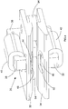
Figure 2 is a cross sectional view of a first sheet handling apparatus of the sheet processing apparatus ofFigure 1 ; -
Figure 3 is a schematic side view of the sheet handling apparatus ofFigure 2 in operation applying force to a sheet of material; -
Figure 4 is a perspective front and side view of the sheet handling apparatus ofFigure 2 ; -
Figure 5 is a perspective side and rear view of the sheet handling apparatus ofFigure 2 ; -
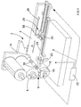
Figure 6 is a perspective view of a second sheet handling apparatus of the sheet processing apparatus ofFigure 1 ; -
Figure 7 is a plan view of the second sheet handling apparatus ofFigure 6 with a gripper blade thereof removed; and -
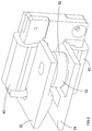
Figure 8 is a perspective view of a magnet and coil assembly of the apparatus ofFigures 6 and 7 . - Referring to
Figure 1 , asheet processing apparatus 2 such as a sheet printing apparatus or a sheet coating apparatus embodying the present invention applies ink or coating material to ametal sheet 4 at a gap 6 between ablanket cylinder 8 and animpression cylinder 10. Registration of a leadingedge 14 of thesheet 4 with theimpression cylinder 10 is achieved by means of a pair offront lay devices 16 with accompanying gripper blades 60 (Figure 6 ) which cooperate withrespective notches 18 in theimpression cylinder 10 to limit forward travel of thesheet 4 in the direction of arrow A and move with theimpression cylinder 10 to cause registration of the leadingedge 14 of thesheet 4 with thecylinder 10. - At the same time, a first sheet handling apparatus in the form of a
sidelay assembly 20 embodying the present invention applies a tensile attractive force to eachside edge 24 of thesheet 4 to limit movement of thesheet 4 in a direction transverse to arrow A, while allowing movement of thesheet 4 in the direction of arrow A. Thesheet 4 is fed to the gap 6 between therollers apparatus including pushers - Referring to
Figures 2 to 5 , eachsidelay assembly 20 is controlled bycontroller 22 and has an uppersheet guide plate 32 and a lowersheet guide plate 34 forming atapering gap 36 for location of theside edge 24 of thesheet 4 therein such that thesheet 4 moves out of the plane of the drawing inFigures 2 and3 . Thesidelay assembly 20 is provided with asoft iron core 38 around which afirst coil 40 and asecond coil 42 are wound, the first 40 and second 42 coils being connected in parallel such that they generate generally identical magnetic flux. Thesoft iron core 38 defines a pair ofnorth poles respective apertures south pole 52 adjacent to which a pair ofregistration rollers 54 is rotatably mounted. When the first 40 and second 42 coils are energised, they produce respectivemagnetic fluxes north poles sheet 4 to thesouth pole 52 such that substantially equal and opposite vertical forces are applied to thesheet 4 in the region between thenorth poles sheet 4 by thesouth pole 52 which draws thesheet 4 into engagement with theregistration rollers 54. - The sidelay assemblies 20 also control the pushing force of the
feeder apparatus sheet 4 by preventing thesheet 4 moving away from thepushers pushers sheet handling assembly 20 as shown inFigures 2-5 which applies a gripping force to rear edge 58 (Figure 1 ) of thesheet 4, thereby removing the need for complex friction controlling devices to prevent thesheet 4 from moving away from thepushers - Referring to
Figures 6 to 8 , afront lay device 16 ofFigure 1 is described in greater detail. Thefront lay device 16 is a complete assembly that is pivoted aboutpivot axis 62. Asoft iron core 66, around which afirst coil 68 and asecond coil 70 are wound, is mounted to thebody 64 and defines a pair ofnorth poles 72 and asouth pole 74 arranged between thenorth poles 72. - In operation, the
gripper assembly 16 is pivoted aboutpivot axis 62 to expose aslot 76 at the level of thepoles inclined surfaces 78. When the first 68 and second 70 coils are energised, the leading edge of thesheet 4 is attracted towards thepoles inclined surfaces 78 to come into abutment withcarbide tips 80 arranged between respective north 72 and south 74 pole pairs. Thegripper assembly 16 is then pivoted to mechanically grip thesheet 4 against theimpression cylinder 10, ready to be printed in the correct position/orientation. - It will be appreciated by persons skilled in the art that the above embodiment has been described by way of example only and not in any limitative sense, and that various alternations and modifications are possible without departure from the scope of the invention as defined by the appended claims. For example, the
sidelay assembly 20 shown inFigure 1 as stationary relative to the frame of theapparatus 2 could move with thesheet 2 such that there is zero relative velocity between thesheet 4 and thesidelay assembly 20. Alternatively, or in addition, the use of the sheet handling apparatus embedded intofront lay devices 16 enables thefeeder apparatus
Claims (13)
- A sheet handling apparatus for handling a sheet (4) of material in a sheet processing apparatus, the sheet handling apparatus comprising:-at least one engaging portion (36, 54) for engaging an edge (24) of a sheet of material being fed in a feeding direction relative to a sheet processing component of a sheet processing apparatus; andcharacterized by magnetic flux generating means for generating magnetic flux passing through an edge region of the sheet of material such that a first magnetic force is applied to said sheet to urge said sheet towards at least one said engaging portion.
- An apparatus according to claim 1, wherein said magnetic flux generating means is adapted to generate magnetic flux passing through an edge region of said sheet such that opposed second and third magnetic forces are applied to said sheet in a direction transverse to a surface of said sheet.
- An apparatus according to claim 1 or 2, wherein the magnetic flux generating means is adapted to provide at least one pair of first magnetic poles of a first polarity, and at least one second pole of a second polarity, opposite to said first polarity, such that magnetic flux passing from a said first magnetic pole to a said second magnetic pole passes through said sheet.
- An apparatus according to claim 3, wherein the magnetic flux generating means has a magnetic flux concentrating portion for concentrating magnetic flux therein and defining at least one pair of said first poles and at least one said second pole.
- An apparatus according to claim 3 or 4, wherein at least one pair of said first magnetic poles is arranged such that said sheet can pass therebetween.
- An apparatus according to any one of the preceding claims, wherein the magnetic flux generating means comprises at least one first coil and at least one second coil.
- An apparatus according to claim 6, wherein at least one said first coil is arranged in use on a first side of said sheet and at least one said second coil is arranged in use on a second side of said sheet.
- An apparatus according to claim 6 or 7, wherein at least one said first coil and at least one said second coil are connected in parallel.
- An apparatus according to any one of the preceding claims, further comprising mechanical gripper means for gripping said sheet.
- A sheet processing apparatus including at least one sheet handling apparatus according to any one of the preceding claims.
- An apparatus according to claim 10, wherein at least one said sheet handling apparatus is adapted to apply a force to said sheet adjacent a side edge thereof relative to a feeding direction of the sheet.
- An apparatus according to claim 10 or 11, wherein at least one said sheet handling apparatus is adapted to apply a force to said sheet adjacent a rear edge thereof relative to a feeding direction of the sheet.
- An apparatus according to any one of claims 10 to 12, wherein at least one said sheet handling apparatus is adapted to apply a force to said sheet adjacent a leading edge thereof relative to a feeding direction of the sheet.
Priority Applications (2)
| Application Number | Priority Date | Filing Date | Title |
|---|---|---|---|
| EP14160570.9A EP2921441B1 (en) | 2014-03-18 | 2014-03-18 | Sheet handling apparatus for sheet processing apparatus |
| PCT/EP2014/072902 WO2015139786A1 (en) | 2014-03-18 | 2014-10-24 | Sheet handling apparatus for sheet processing apparatus |
Applications Claiming Priority (1)
| Application Number | Priority Date | Filing Date | Title |
|---|---|---|---|
| EP14160570.9A EP2921441B1 (en) | 2014-03-18 | 2014-03-18 | Sheet handling apparatus for sheet processing apparatus |
Publications (2)
| Publication Number | Publication Date |
|---|---|
| EP2921441A1 EP2921441A1 (en) | 2015-09-23 |
| EP2921441B1 true EP2921441B1 (en) | 2016-07-27 |
Family
ID=50289524
Family Applications (1)
| Application Number | Title | Priority Date | Filing Date |
|---|---|---|---|
| EP14160570.9A Not-in-force EP2921441B1 (en) | 2014-03-18 | 2014-03-18 | Sheet handling apparatus for sheet processing apparatus |
Country Status (2)
| Country | Link |
|---|---|
| EP (1) | EP2921441B1 (en) |
| WO (1) | WO2015139786A1 (en) |
Families Citing this family (1)
| Publication number | Priority date | Publication date | Assignee | Title |
|---|---|---|---|---|
| DE102018126049B4 (en) * | 2018-10-19 | 2020-08-27 | Koenig & Bauer Ag | Tabular substrate processing machine with a system, method for setting up and method for operating a system |
Family Cites Families (4)
| Publication number | Priority date | Publication date | Assignee | Title |
|---|---|---|---|---|
| DE4445638A1 (en) * | 1994-12-21 | 1996-06-27 | Otto Kunzi | Feeding device for sheet metal printing machines |
| DE19819888B4 (en) * | 1998-05-04 | 2004-07-08 | Ltg Holding Gmbh | Method and device for feeding sheet material |
| DE10116980A1 (en) * | 2000-05-02 | 2001-11-08 | Heidelberger Druckmasch Ag | Sheet alignment device for printers fixes sheet on positioning table which is movable by position drive in and/or across sheet running direction and or can be swivelled about orthogonal axis |
| DE102008034917A1 (en) * | 2008-07-26 | 2010-01-28 | Kba-Metalprint Gmbh | Apparatus and methods for leading edge and side edge alignment of a tabular article |
-
2014
- 2014-03-18 EP EP14160570.9A patent/EP2921441B1/en not_active Not-in-force
- 2014-10-24 WO PCT/EP2014/072902 patent/WO2015139786A1/en not_active Ceased
Also Published As
| Publication number | Publication date |
|---|---|
| WO2015139786A1 (en) | 2015-09-24 |
| EP2921441A1 (en) | 2015-09-23 |
Similar Documents
| Publication | Publication Date | Title |
|---|---|---|
| US20080289527A1 (en) | Device and Method for Correcting Lateral Position of a Printing Substrate | |
| JP2010012782A (en) | Method of individuating at least two bridges in segmented transport system for print material | |
| JP2015514649A (en) | Apparatus and method for conveying a substrate in a printing press | |
| KR102069990B1 (en) | Sheet Separation Apparatus, Sheet Separation Method, and Manufacturing Method of Sheet Shape Secondary Battery | |
| CN103144424B (en) | A kind of electronic registering system and method for work thereof | |
| US20120073119A1 (en) | Method for Applying Magnets | |
| US6923119B1 (en) | Sheet transport system for a rotary printing press | |
| JP2016068420A (en) | Printer | |
| JPH11268845A (en) | Device for conveying paper sheet or signature | |
| US4018155A (en) | Ballistic print hammer assembly | |
| US10569578B2 (en) | Printing apparatus | |
| US9421797B2 (en) | Printer having separating device | |
| EP2921441A1 (en) | Sheet handling apparatus for sheet processing apparatus | |
| CN105417220B (en) | Equipment for stacking will to be assisted to be combined with main stacking | |
| US8561988B1 (en) | Media hold-down for printing system | |
| DE19819888B4 (en) | Method and device for feeding sheet material | |
| JP5744479B2 (en) | Insertion device | |
| US7287749B2 (en) | Transport system in a machine that processes printing material | |
| WO2007116615A1 (en) | Print head and printer equipped with such print head | |
| CN103449237A (en) | Paper cutting device, post-processing device and image forming system | |
| US20200346886A1 (en) | Gimbaled monoclamps | |
| US20150059607A1 (en) | Device for print finishing | |
| JP5672488B2 (en) | Recording medium conveying apparatus and image forming apparatus | |
| US1300563A (en) | Sheet-registering mechanism. | |
| US3182995A (en) | Means for separating superimposed sheets |
Legal Events
| Date | Code | Title | Description |
|---|---|---|---|
| PUAI | Public reference made under article 153(3) epc to a published international application that has entered the european phase |
Free format text: ORIGINAL CODE: 0009012 |
|
| 17P | Request for examination filed |
Effective date: 20141024 |
|
| AK | Designated contracting states |
Kind code of ref document: A1 Designated state(s): AL AT BE BG CH CY CZ DE DK EE ES FI FR GB GR HR HU IE IS IT LI LT LU LV MC MK MT NL NO PL PT RO RS SE SI SK SM TR |
|
| AX | Request for extension of the european patent |
Extension state: BA ME |
|
| GRAP | Despatch of communication of intention to grant a patent |
Free format text: ORIGINAL CODE: EPIDOSNIGR1 |
|
| INTG | Intention to grant announced |
Effective date: 20160218 |
|
| GRAS | Grant fee paid |
Free format text: ORIGINAL CODE: EPIDOSNIGR3 |
|
| GRAA | (expected) grant |
Free format text: ORIGINAL CODE: 0009210 |
|
| AK | Designated contracting states |
Kind code of ref document: B1 Designated state(s): AL AT BE BG CH CY CZ DE DK EE ES FI FR GB GR HR HU IE IS IT LI LT LU LV MC MK MT NL NO PL PT RO RS SE SI SK SM TR |
|
| REG | Reference to a national code |
Ref country code: GB Ref legal event code: FG4D |
|
| REG | Reference to a national code |
Ref country code: CH Ref legal event code: EP |
|
| REG | Reference to a national code |
Ref country code: AT Ref legal event code: REF Ref document number: 815630 Country of ref document: AT Kind code of ref document: T Effective date: 20160815 |
|
| REG | Reference to a national code |
Ref country code: IE Ref legal event code: FG4D |
|
| REG | Reference to a national code |
Ref country code: DE Ref legal event code: R096 Ref document number: 602014002819 Country of ref document: DE |
|
| REG | Reference to a national code |
Ref country code: LT Ref legal event code: MG4D |
|
| REG | Reference to a national code |
Ref country code: NL Ref legal event code: MP Effective date: 20160727 |
|
| REG | Reference to a national code |
Ref country code: AT Ref legal event code: MK05 Ref document number: 815630 Country of ref document: AT Kind code of ref document: T Effective date: 20160727 |
|
| PG25 | Lapsed in a contracting state [announced via postgrant information from national office to epo] |
Ref country code: NO Free format text: LAPSE BECAUSE OF FAILURE TO SUBMIT A TRANSLATION OF THE DESCRIPTION OR TO PAY THE FEE WITHIN THE PRESCRIBED TIME-LIMIT Effective date: 20161027 Ref country code: LT Free format text: LAPSE BECAUSE OF FAILURE TO SUBMIT A TRANSLATION OF THE DESCRIPTION OR TO PAY THE FEE WITHIN THE PRESCRIBED TIME-LIMIT Effective date: 20160727 Ref country code: IS Free format text: LAPSE BECAUSE OF FAILURE TO SUBMIT A TRANSLATION OF THE DESCRIPTION OR TO PAY THE FEE WITHIN THE PRESCRIBED TIME-LIMIT Effective date: 20161127 Ref country code: FI Free format text: LAPSE BECAUSE OF FAILURE TO SUBMIT A TRANSLATION OF THE DESCRIPTION OR TO PAY THE FEE WITHIN THE PRESCRIBED TIME-LIMIT Effective date: 20160727 Ref country code: HR Free format text: LAPSE BECAUSE OF FAILURE TO SUBMIT A TRANSLATION OF THE DESCRIPTION OR TO PAY THE FEE WITHIN THE PRESCRIBED TIME-LIMIT Effective date: 20160727 Ref country code: NL Free format text: LAPSE BECAUSE OF FAILURE TO SUBMIT A TRANSLATION OF THE DESCRIPTION OR TO PAY THE FEE WITHIN THE PRESCRIBED TIME-LIMIT Effective date: 20160727 Ref country code: RS Free format text: LAPSE BECAUSE OF FAILURE TO SUBMIT A TRANSLATION OF THE DESCRIPTION OR TO PAY THE FEE WITHIN THE PRESCRIBED TIME-LIMIT Effective date: 20160727 Ref country code: IT Free format text: LAPSE BECAUSE OF FAILURE TO SUBMIT A TRANSLATION OF THE DESCRIPTION OR TO PAY THE FEE WITHIN THE PRESCRIBED TIME-LIMIT Effective date: 20160727 |
|
| PG25 | Lapsed in a contracting state [announced via postgrant information from national office to epo] |
Ref country code: GR Free format text: LAPSE BECAUSE OF FAILURE TO SUBMIT A TRANSLATION OF THE DESCRIPTION OR TO PAY THE FEE WITHIN THE PRESCRIBED TIME-LIMIT Effective date: 20161028 Ref country code: ES Free format text: LAPSE BECAUSE OF FAILURE TO SUBMIT A TRANSLATION OF THE DESCRIPTION OR TO PAY THE FEE WITHIN THE PRESCRIBED TIME-LIMIT Effective date: 20160727 Ref country code: PL Free format text: LAPSE BECAUSE OF FAILURE TO SUBMIT A TRANSLATION OF THE DESCRIPTION OR TO PAY THE FEE WITHIN THE PRESCRIBED TIME-LIMIT Effective date: 20160727 Ref country code: LV Free format text: LAPSE BECAUSE OF FAILURE TO SUBMIT A TRANSLATION OF THE DESCRIPTION OR TO PAY THE FEE WITHIN THE PRESCRIBED TIME-LIMIT Effective date: 20160727 Ref country code: PT Free format text: LAPSE BECAUSE OF FAILURE TO SUBMIT A TRANSLATION OF THE DESCRIPTION OR TO PAY THE FEE WITHIN THE PRESCRIBED TIME-LIMIT Effective date: 20161128 Ref country code: BE Free format text: LAPSE BECAUSE OF FAILURE TO SUBMIT A TRANSLATION OF THE DESCRIPTION OR TO PAY THE FEE WITHIN THE PRESCRIBED TIME-LIMIT Effective date: 20160727 Ref country code: SE Free format text: LAPSE BECAUSE OF FAILURE TO SUBMIT A TRANSLATION OF THE DESCRIPTION OR TO PAY THE FEE WITHIN THE PRESCRIBED TIME-LIMIT Effective date: 20160727 Ref country code: AT Free format text: LAPSE BECAUSE OF FAILURE TO SUBMIT A TRANSLATION OF THE DESCRIPTION OR TO PAY THE FEE WITHIN THE PRESCRIBED TIME-LIMIT Effective date: 20160727 |
|
| PG25 | Lapsed in a contracting state [announced via postgrant information from national office to epo] |
Ref country code: RO Free format text: LAPSE BECAUSE OF FAILURE TO SUBMIT A TRANSLATION OF THE DESCRIPTION OR TO PAY THE FEE WITHIN THE PRESCRIBED TIME-LIMIT Effective date: 20160727 Ref country code: EE Free format text: LAPSE BECAUSE OF FAILURE TO SUBMIT A TRANSLATION OF THE DESCRIPTION OR TO PAY THE FEE WITHIN THE PRESCRIBED TIME-LIMIT Effective date: 20160727 |
|
| REG | Reference to a national code |
Ref country code: DE Ref legal event code: R097 Ref document number: 602014002819 Country of ref document: DE |
|
| PG25 | Lapsed in a contracting state [announced via postgrant information from national office to epo] |
Ref country code: SM Free format text: LAPSE BECAUSE OF FAILURE TO SUBMIT A TRANSLATION OF THE DESCRIPTION OR TO PAY THE FEE WITHIN THE PRESCRIBED TIME-LIMIT Effective date: 20160727 Ref country code: SK Free format text: LAPSE BECAUSE OF FAILURE TO SUBMIT A TRANSLATION OF THE DESCRIPTION OR TO PAY THE FEE WITHIN THE PRESCRIBED TIME-LIMIT Effective date: 20160727 Ref country code: CZ Free format text: LAPSE BECAUSE OF FAILURE TO SUBMIT A TRANSLATION OF THE DESCRIPTION OR TO PAY THE FEE WITHIN THE PRESCRIBED TIME-LIMIT Effective date: 20160727 Ref country code: DK Free format text: LAPSE BECAUSE OF FAILURE TO SUBMIT A TRANSLATION OF THE DESCRIPTION OR TO PAY THE FEE WITHIN THE PRESCRIBED TIME-LIMIT Effective date: 20160727 Ref country code: BG Free format text: LAPSE BECAUSE OF FAILURE TO SUBMIT A TRANSLATION OF THE DESCRIPTION OR TO PAY THE FEE WITHIN THE PRESCRIBED TIME-LIMIT Effective date: 20161027 |
|
| PLBE | No opposition filed within time limit |
Free format text: ORIGINAL CODE: 0009261 |
|
| STAA | Information on the status of an ep patent application or granted ep patent |
Free format text: STATUS: NO OPPOSITION FILED WITHIN TIME LIMIT |
|
| 26N | No opposition filed |
Effective date: 20170502 |
|
| PG25 | Lapsed in a contracting state [announced via postgrant information from national office to epo] |
Ref country code: SI Free format text: LAPSE BECAUSE OF FAILURE TO SUBMIT A TRANSLATION OF THE DESCRIPTION OR TO PAY THE FEE WITHIN THE PRESCRIBED TIME-LIMIT Effective date: 20160727 |
|
| REG | Reference to a national code |
Ref country code: DE Ref legal event code: R119 Ref document number: 602014002819 Country of ref document: DE |
|
| REG | Reference to a national code |
Ref country code: CH Ref legal event code: PL |
|
| PG25 | Lapsed in a contracting state [announced via postgrant information from national office to epo] |
Ref country code: MC Free format text: LAPSE BECAUSE OF FAILURE TO SUBMIT A TRANSLATION OF THE DESCRIPTION OR TO PAY THE FEE WITHIN THE PRESCRIBED TIME-LIMIT Effective date: 20160727 |
|
| REG | Reference to a national code |
Ref country code: IE Ref legal event code: MM4A |
|
| REG | Reference to a national code |
Ref country code: FR Ref legal event code: ST Effective date: 20171130 |
|
| PG25 | Lapsed in a contracting state [announced via postgrant information from national office to epo] |
Ref country code: FR Free format text: LAPSE BECAUSE OF NON-PAYMENT OF DUE FEES Effective date: 20170331 Ref country code: LU Free format text: LAPSE BECAUSE OF NON-PAYMENT OF DUE FEES Effective date: 20170318 Ref country code: DE Free format text: LAPSE BECAUSE OF NON-PAYMENT OF DUE FEES Effective date: 20171003 |
|
| PG25 | Lapsed in a contracting state [announced via postgrant information from national office to epo] |
Ref country code: CH Free format text: LAPSE BECAUSE OF NON-PAYMENT OF DUE FEES Effective date: 20170331 Ref country code: IE Free format text: LAPSE BECAUSE OF NON-PAYMENT OF DUE FEES Effective date: 20170318 Ref country code: LI Free format text: LAPSE BECAUSE OF NON-PAYMENT OF DUE FEES Effective date: 20170331 |
|
| PG25 | Lapsed in a contracting state [announced via postgrant information from national office to epo] |
Ref country code: MT Free format text: LAPSE BECAUSE OF NON-PAYMENT OF DUE FEES Effective date: 20170318 |
|
| PG25 | Lapsed in a contracting state [announced via postgrant information from national office to epo] |
Ref country code: AL Free format text: LAPSE BECAUSE OF FAILURE TO SUBMIT A TRANSLATION OF THE DESCRIPTION OR TO PAY THE FEE WITHIN THE PRESCRIBED TIME-LIMIT Effective date: 20160727 |
|
| GBPC | Gb: european patent ceased through non-payment of renewal fee |
Effective date: 20180318 |
|
| PG25 | Lapsed in a contracting state [announced via postgrant information from national office to epo] |
Ref country code: GB Free format text: LAPSE BECAUSE OF NON-PAYMENT OF DUE FEES Effective date: 20180318 |
|
| PG25 | Lapsed in a contracting state [announced via postgrant information from national office to epo] |
Ref country code: HU Free format text: LAPSE BECAUSE OF FAILURE TO SUBMIT A TRANSLATION OF THE DESCRIPTION OR TO PAY THE FEE WITHIN THE PRESCRIBED TIME-LIMIT; INVALID AB INITIO Effective date: 20140318 |
|
| PG25 | Lapsed in a contracting state [announced via postgrant information from national office to epo] |
Ref country code: CY Free format text: LAPSE BECAUSE OF FAILURE TO SUBMIT A TRANSLATION OF THE DESCRIPTION OR TO PAY THE FEE WITHIN THE PRESCRIBED TIME-LIMIT Effective date: 20160727 |
|
| PG25 | Lapsed in a contracting state [announced via postgrant information from national office to epo] |
Ref country code: MK Free format text: LAPSE BECAUSE OF FAILURE TO SUBMIT A TRANSLATION OF THE DESCRIPTION OR TO PAY THE FEE WITHIN THE PRESCRIBED TIME-LIMIT Effective date: 20160727 |
|
| PG25 | Lapsed in a contracting state [announced via postgrant information from national office to epo] |
Ref country code: TR Free format text: LAPSE BECAUSE OF FAILURE TO SUBMIT A TRANSLATION OF THE DESCRIPTION OR TO PAY THE FEE WITHIN THE PRESCRIBED TIME-LIMIT Effective date: 20160727 |