EP2921403B1 - A shock absorber and a method of determining the level of liquid in a shock absorber - Google Patents
A shock absorber and a method of determining the level of liquid in a shock absorber Download PDFInfo
- Publication number
- EP2921403B1 EP2921403B1 EP14160746.5A EP14160746A EP2921403B1 EP 2921403 B1 EP2921403 B1 EP 2921403B1 EP 14160746 A EP14160746 A EP 14160746A EP 2921403 B1 EP2921403 B1 EP 2921403B1
- Authority
- EP
- European Patent Office
- Prior art keywords
- waveguide
- liquid
- reflected
- cavity
- signal
- Prior art date
- Legal status (The legal status is an assumption and is not a legal conclusion. Google has not performed a legal analysis and makes no representation as to the accuracy of the status listed.)
- Active
Links
- 239000007788 liquid Substances 0.000 title claims description 76
- 230000035939 shock Effects 0.000 title claims description 61
- 239000006096 absorbing agent Substances 0.000 title claims description 60
- 238000000034 method Methods 0.000 title claims description 21
- 238000004891 communication Methods 0.000 claims description 22
- 230000001939 inductive effect Effects 0.000 claims description 8
- 238000012546 transfer Methods 0.000 claims description 8
- 239000007787 solid Substances 0.000 claims description 2
- 238000004458 analytical method Methods 0.000 claims 1
- 239000012530 fluid Substances 0.000 description 40
- 238000005259 measurement Methods 0.000 description 18
- 238000010586 diagram Methods 0.000 description 7
- 230000005540 biological transmission Effects 0.000 description 6
- 230000008878 coupling Effects 0.000 description 5
- 238000010168 coupling process Methods 0.000 description 5
- 238000005859 coupling reaction Methods 0.000 description 5
- 230000003287 optical effect Effects 0.000 description 4
- 239000000463 material Substances 0.000 description 3
- 239000000523 sample Substances 0.000 description 3
- 230000009471 action Effects 0.000 description 2
- 238000011109 contamination Methods 0.000 description 2
- 239000006260 foam Substances 0.000 description 2
- 238000012423 maintenance Methods 0.000 description 2
- 230000035945 sensitivity Effects 0.000 description 2
- 230000008859 change Effects 0.000 description 1
- 238000013016 damping Methods 0.000 description 1
- 230000001419 dependent effect Effects 0.000 description 1
- 238000013461 design Methods 0.000 description 1
- 230000005284 excitation Effects 0.000 description 1
- 230000036541 health Effects 0.000 description 1
- 239000012535 impurity Substances 0.000 description 1
- 230000006698 induction Effects 0.000 description 1
- 238000012545 processing Methods 0.000 description 1
- 230000008439 repair process Effects 0.000 description 1
- 230000004044 response Effects 0.000 description 1
- 238000001228 spectrum Methods 0.000 description 1
Images


Classifications
-
- F—MECHANICAL ENGINEERING; LIGHTING; HEATING; WEAPONS; BLASTING
- F16—ENGINEERING ELEMENTS AND UNITS; GENERAL MEASURES FOR PRODUCING AND MAINTAINING EFFECTIVE FUNCTIONING OF MACHINES OR INSTALLATIONS; THERMAL INSULATION IN GENERAL
- F16F—SPRINGS; SHOCK-ABSORBERS; MEANS FOR DAMPING VIBRATION
- F16F9/00—Springs, vibration-dampers, shock-absorbers, or similarly-constructed movement-dampers using a fluid or the equivalent as damping medium
- F16F9/06—Springs, vibration-dampers, shock-absorbers, or similarly-constructed movement-dampers using a fluid or the equivalent as damping medium using both gas and liquid
- F16F9/061—Mono-tubular units
-
- B—PERFORMING OPERATIONS; TRANSPORTING
- B64—AIRCRAFT; AVIATION; COSMONAUTICS
- B64C—AEROPLANES; HELICOPTERS
- B64C25/00—Alighting gear
- B64C25/32—Alighting gear characterised by elements which contact the ground or similar surface
- B64C25/58—Arrangements or adaptations of shock-absorbers or springs
- B64C25/60—Oleo legs
-
- B—PERFORMING OPERATIONS; TRANSPORTING
- B64—AIRCRAFT; AVIATION; COSMONAUTICS
- B64F—GROUND OR AIRCRAFT-CARRIER-DECK INSTALLATIONS SPECIALLY ADAPTED FOR USE IN CONNECTION WITH AIRCRAFT; DESIGNING, MANUFACTURING, ASSEMBLING, CLEANING, MAINTAINING OR REPAIRING AIRCRAFT, NOT OTHERWISE PROVIDED FOR; HANDLING, TRANSPORTING, TESTING OR INSPECTING AIRCRAFT COMPONENTS, NOT OTHERWISE PROVIDED FOR
- B64F5/00—Designing, manufacturing, assembling, cleaning, maintaining or repairing aircraft, not otherwise provided for; Handling, transporting, testing or inspecting aircraft components, not otherwise provided for
- B64F5/60—Testing or inspecting aircraft components or systems
-
- F—MECHANICAL ENGINEERING; LIGHTING; HEATING; WEAPONS; BLASTING
- F16—ENGINEERING ELEMENTS AND UNITS; GENERAL MEASURES FOR PRODUCING AND MAINTAINING EFFECTIVE FUNCTIONING OF MACHINES OR INSTALLATIONS; THERMAL INSULATION IN GENERAL
- F16F—SPRINGS; SHOCK-ABSORBERS; MEANS FOR DAMPING VIBRATION
- F16F9/00—Springs, vibration-dampers, shock-absorbers, or similarly-constructed movement-dampers using a fluid or the equivalent as damping medium
- F16F9/32—Details
- F16F9/3264—Arrangements for indicating, e.g. fluid level; Arrangements for checking dampers
-
- F—MECHANICAL ENGINEERING; LIGHTING; HEATING; WEAPONS; BLASTING
- F16—ENGINEERING ELEMENTS AND UNITS; GENERAL MEASURES FOR PRODUCING AND MAINTAINING EFFECTIVE FUNCTIONING OF MACHINES OR INSTALLATIONS; THERMAL INSULATION IN GENERAL
- F16F—SPRINGS; SHOCK-ABSORBERS; MEANS FOR DAMPING VIBRATION
- F16F9/00—Springs, vibration-dampers, shock-absorbers, or similarly-constructed movement-dampers using a fluid or the equivalent as damping medium
- F16F9/32—Details
- F16F9/3292—Sensor arrangements
-
- G—PHYSICS
- G01—MEASURING; TESTING
- G01F—MEASURING VOLUME, VOLUME FLOW, MASS FLOW OR LIQUID LEVEL; METERING BY VOLUME
- G01F23/00—Indicating or measuring liquid level or level of fluent solid material, e.g. indicating in terms of volume or indicating by means of an alarm
- G01F23/22—Indicating or measuring liquid level or level of fluent solid material, e.g. indicating in terms of volume or indicating by means of an alarm by measuring physical variables, other than linear dimensions, pressure or weight, dependent on the level to be measured, e.g. by difference of heat transfer of steam or water
- G01F23/28—Indicating or measuring liquid level or level of fluent solid material, e.g. indicating in terms of volume or indicating by means of an alarm by measuring physical variables, other than linear dimensions, pressure or weight, dependent on the level to be measured, e.g. by difference of heat transfer of steam or water by measuring the variations of parameters of electromagnetic or acoustic waves applied directly to the liquid or fluent solid material
- G01F23/284—Electromagnetic waves
Definitions
- an oleo-pneumatic shock absorber used in aircraft landing gear depends substantially on the level of hydraulic fluid situated therein.
- Current in-service methods for establishing the condition of an oleo-pneumatic shock absorber are based on measurement of temperature, gas pressure and shock absorber travel which are then used to estimate the level of hydraulic fluid in the shock absorber. Whilst measuring these parameters is straightforward, incorrect conclusions can be drawn and inappropriate actions can be taken if, for example, the level of hydraulic fluid within the shock absorber is estimated to be correct when in fact it is too low.
- An incorrectly serviced shock absorber containing, for example, too little or too much hydraulic fluid will cause the landing gear to perform outside its design boundaries and in extreme cases could cause the shock absorber and thus the landing gear to fail.
- ultrasonic techniques transmit ultrasonic pulses towards the gas-oil boundary and measure time of flight of received waves reflected off the boundary.
- foam and fluid contamination at the gas-liquid boundary tends to cause significant scattering and attenuation of the transmitted ultrasonic signal and piezo transducers used to generate the ultrasonic signals are fragile and thus susceptible to failure from the shock of impact of an aircraft landing gear with the ground.
- a telescopic shock absorber comprising: a housing; a cavity located within the housing and containing a liquid and a gas; and a sensor for measuring the level of the liquid in the cavity, the sensor comprising: a first waveguide having a first end and a second end; and a communications interface operable to transfer electrical signals between the first waveguide and the exterior of the housing, wherein the first waveguide is arranged such that when the shock absorber is in normal use the first end is surrounded by the gas and the second end is immersed in the liquid.
- the first waveguide By locating the first waveguide within the cavity across the gas-liquid boundary, an accurate measurement of the level of hydraulic fluid within the shock absorber can be ascertained.
- the first waveguide is able to provide an accurate and substantially continuous measurement of the level of fluid within the cavity which is substantially unaffected by foam and fluid contamination at the gas-liquid boundary.
- the shock absorber comprises a transceiver coupled to one of the ends of the first waveguide.
- the transceiver may then couple electromagnetic (EM) waves into the first waveguide and receive reflected EM waves from the first waveguide.
- EM electromagnetic
- the end of the first waveguide which is not coupled to the transceiver may be shorted so as to act as a node from which EM waves transmitted into the waveguide are reflected.
- a change in frequency of peaks in amplitude of reflected waves can be used to determine the average dielectric constant of material within the waveguide and thus the ratio of liquid relative to gas.
- the shock absorber may further comprise a calibration waveguide fully immersed in the liquid when the shock absorber is in normal use, the transceiver being coupled to an end of the first calibration waveguide.
- This calibration waveguide may be used to more accurately measure the dielectric constant of the liquid such that the measure of the level of the liquid in the first waveguide can be improved.
- the shock absorber may further comprise a second waveguide disposed within the cavity having a first end and a second end, the second waveguide arranged such that when the shock absorber is in normal use, the first end of the second waveguide is immersed in the liquid and the second end of the second waveguide is immersed in the gas.
- the communication interface may be operable to transfer electrical signals between the second waveguide and the exterior of the housing.
- the transceiver is preferably coupled to the first end of the first waveguide and the first end of the second waveguide.
- the accuracy of measurement of fluid level is maximised when the fluid level is closest to the end into which EM waves are coupled.
- the first and/or second waveguides may be a coaxial waveguide comprising a hollow tube arranged coaxially around a solid core.
- Each hollow tube is preferably perforated such that fluid is able to flow through the waveguide(s) so that performance of the shock absorber is not affected by their presence.
- the communications interface may comprise a port in a wall of the housing, arranged to pass one or more transmission mediums through the housing wall but prevent leakage of fluid or gas in or out of the housing.
- the communications interface may comprise an inductive loop located proximate to a wall of the cavity thereby eradicating issues associated with fluid and gas leakage through a port which may otherwise be required in the wall.
- a method of measuring the level of liquid in a telescopic shock absorber comprising a housing and a cavity located within the housing and containing a liquid and a gas, the method comprising: transmitting an electromagnetic signal over a range of frequencies into a first end or a second end of a first waveguide located within the cavity, the first end surrounded by the gas, the second end immersed in the liquid; receiving a reflected EM signal from the first waveguide; analysing the reflected EM signal to detect one or more peaks in the reflected EM signal; and determining the level of the liquid in the cavity as a function of the frequency of the peaks and the dielectric constants of the liquid and the gas.
- the method may further comprise transmitting an electromagnetic signal over a range of frequencies into the calibration waveguide located within the cavity and submerged in the liquid, receiving a reflected EM signal from the calibration waveguide, analysing the reflected EM signal to detect one or more calibration peaks in the reflected EM signal and determining the dielectric constant of the liquid as a function of the frequency of the calibration peaks and at least one dimension of the calibration waveguide.
- the method may further comprise transmitting an electromagnetic signal over a range of frequencies into a further calibration waveguide located within the cavity and surrounded by the gas, receiving a reflected EM signal from the further calibration waveguide, analysing the reflected EM signal to detect one or more further calibration peaks in the reflected EM signal and determining the dielectric constant of the liquid as a function of the frequency of the further calibration peaks and at least one dimension of the waveguide.
- the method may further comprise transmitting an electromagnetic signal over a range of frequencies into a first end of a second waveguide located within the cavity the first end immersed in the liquid, the second waveguide having a second end surrounded by the gas; receiving a reflected EM signal from the first waveguide; analysing the reflected EM signal to detect one or more peaks in the reflected EM signal; and determining the level of the liquid in the cavity as a function of the frequency of the peaks and the dielectric constants of the liquid and the gas.
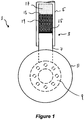
- Figure 1 shows a cross section of a known aircraft landing gear 1.
- the aircraft landing gear 1 comprises a telescopic support leg 3 in the form of an oleo-pneumatic shock absorber (or oleo strut) comprising a housing 5 having a bore into which a rod or piston 7 is slidably disposed. Attached to the lower end of the rod 7 is a wheel axle 9 onto which a wheel 11 may be attached.
- the upper end of the housing 5 (not shown) may be attached in any known manner to the airframe of an aircraft (also not shown). In other embodiments, the orientation of the shock absorber may be flipped such that a wheel is attached to the upper end of the housing 5, the lower end of the rod 7 being coupled to the airframe of an aircraft.
- the gas and hydraulic fluid are substantially separated in normal use as designated by gas 17 and liquid 19 regions shown in Figure 1 .
- the damping properties of the shock absorber 3 are affected by the level of hydraulic fluid present in the cavity 13 and so it is desirable to have an awareness of this level when the landing gear 1 is in service.
- it remains difficult to perform direct in-service measurements of the level of hydraulic fluid in the cavity 13. Accordingly, an estimate may be made based on measurements of temperature, gas pressure and shock absorber travel.
- An aim of the present invention is to provide an improved method of measuring the level of oil in a oleo-pneumatic shock absorber 3.
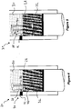
- FIG 2 is a schematic diagram of a shock absorber 20 in accordance with an embodiment of the present invention. Like the shock absorber 3 shown in Figure 1 , the shock absorber 20 of
- Figure 2 comprises a housing 22 defining a bore into which a rod or piston 24 is slidably disposed.
- the bore in the housing 22 and the upper end 26 of the rod 24 define a cavity 28 which is filled with a gas (shown in gas region 30) and a liquid such as hydraulic fluid or oil (shown in the liquid region 32).
- the shock absorber 20 further comprises a sensor, generally designated 34, operable to measure the level of fluid in the cavity 28.
- the sensor 34 comprises a waveguide 36, a communications interface 38, and an optional radio frequency (RF) transceiver 40.
- One end of the waveguide 36 is located in the liquid region 32 and the other, top end is situated in the gas region 30 of the cavity 28.
- the waveguide 36 is a coaxial waveguide having an outer tube 42 coaxially surrounding a central conducting core 44.
- any suitable waveguide may be used.
- a PCB type waveguide such as a stripline, microstrip or other suitable waveguide may be used.
- the tube 42 may be provided with a plurality of perforations. Such perforation permit free movement of fluid through the shock absorber 20 so that the presence of the waveguide 36 in the cavity 28 does not substantially affect the performance of the shock absorber 20.
- the communications interface 38 is operable to transfer electrical signals between components within the cavity, such as the waveguide 36, and components external to the cavity, such as the RF transceiver 40 shown in Figure 2 fixed to the side of housing 22.
- the communication interface 38 may include a sealed port 46 provided through the housing wall.
- the port 46 may include connection means such as one or more sockets for connecting components of the sensor between the cavity and the outside of the housing 22.
- Such components may, for example, connect to the socket(s) via one or more complimentary plugs (not shown).
- components located within the cavity 28 may be hard wired to components located outside of the cavity via cables running through the port 46.
- the port 46 is that it is sealed and thus does not allow fluid or gas to exit and/or enter the cavity 28.
- other techniques may be used to transfer signals across to the exterior of the cavity, such as acoustic, optical and/or wireless transmission, or inductive coupling as will be described in more detail below.
- the RF transceiver 40 is connected to the waveguide 36 via the communications line 38, as shown in Figure 2 .
- the transceiver 40 may be positioned within the cavity 28 and connected between the communications interface 38 and the waveguide 36, as shown in Figure 3 where like parts have been given like numbering. In either case, the transceiver 40 is electrically connected to one end of the waveguide 36 and is operable to couple RF signals into the waveguide 36 and to receive signals reflected out of the waveguide 36.
- the transceiver may be coupled to an end of the waveguide immersed in the liquid region 32 or positioned in the gas region 30.
- the transceiver 40 may be integrated with the waveguide.
- the RF transceiver 40 may comprise a network analyser and/or a processor for processing reflected signals received from the waveguide 36.
- the processor may form part of a separate device not forming part of the sensor 34. Such a device may connect to the transceiver via the communications interface 38.
- the waveguide 36 is preferably shorted at the end opposite to that coupled to the RF transceiver 40. Accordingly, the waveguide acts as a short-circuited transmission line. Waves are coupled into the waveguide 36 by the transceiver 40, travel along the waveguide 36 and are reflected at the shorted end. Reflected waves then travel back up the waveguide 36 and are received at the transceiver 40. Transmitting a wave having a wavelength equal to a multiple of a quarter of the length of the waveguide will create a standing wave in the waveguide 36, causing the waveguide 36 to resonate.
- the resonant frequency of the waveguide 36 depends on the dielectric constant of the material disposed within the waveguide 36 as this affects the speed of travel of waves in the waveguide 36. Since the dielectric constant of the liquid in the liquid region 32 differs from that of the gas region, as the level of liquid in the cavity 28 changes, the dielectric properties of the material (gas and liquid) located within the waveguide also changes. Accordingly, as the liquid level moves up and down the waveguide, the resonant frequency of the waveguide will vary.
- the RF transceiver 40 may couple an RF signal into the waveguide 36.
- the frequency of the transmitted RF signal may be swept over a range of frequencies and subsequent reflected RF signals received and preferably recorded by the RF transceiver 40. Peaks in amplitude of the received RF signals which correspond to resonance in the waveguide may then be recorded, together with the corresponding excitation frequency of the transmitted RF signal. With knowledge of the dielectric constant of both the gas and the liquid, the fluid height in the cavity may then be calculated from the frequency corresponding to maxima in the reflected RF signal.
- the present invention therefore allows for accurate continuous measurement of fluid level in an oleo pneumatic shock absorber. Accordingly, the system may be used as a prognostic maintenance system whereby the rate of loss of fluid can be assessed and decision made on when to undertake corrective action. By measuring the actual fluid level within the shock absorber, ground crew no longer have to rely on unreliable and inaccurate methods of estimating the level of fluid within the cavity.
- the dielectric constant of the gas and liquid disposed in the cavity 28 can vary considerable.
- the dielectric constant of many hydraulic fluids is dependent both on temperature of the liquid and the amount of gas dissolved therein.
- the inventors have realised that the accuracy of measurement could be further improved by measuring of the dielectric properties of the fluid within the liquid region 32.
- Figure 4 shows a variation of the shock absorbers shown in Figures 2 and 3 , the sensor 34 further comprising a calibration waveguide 48 coupled to the RF transceiver and located within the liquid region 32 of the cavity 28.
- the RF transceiver 40 may transmit a swept RF signal into the calibration waveguide 48 and receive and preferably record the reflected RF signal.
- the transmission frequency at which resonance of the waveguide 48 occurs may be recorded.
- the senor 34 may comprise a further calibration waveguide (not shown) located in the gas region 30 so as to provide a realtime measurement of the dielectric properties of the gas.
- a further calibration waveguide may operate in a similar manner to the calibration waveguide 48 shown in Figure 4 .
- a secondary waveguide 50 is provided which is upturned relative to the main waveguide 36.
- the end of the secondary waveguide 50 immersed in the liquid region 32 is coupled to the communications interface 38 and thus to the RF transceiver 40.
- the opposite end of the secondary waveguide 50 is situated in the gas region 30 and is shorted.
- the secondary waveguide 50 is preferably used to determine the level of the liquid in the cavity 28 since the sensitivity of measurement by the secondary waveguide 50 will be higher.
- the main waveguide 36 may be used to measure the level of liquid in the cavity.
- both waveguides 36 and 50 may be used to measure the level of liquid, such measurements being combined, averaged or analysed in a manner suitable to ascertain a more accurate measurement of the level of fluid in the cavity 28.
- the RF transceiver 40 may not form part of the sensor 34. Instead, as shown in Figure 6 , the RF transceiver may form part of a sensor interrogation device 52 which may be coupled to the waveguide via the communications interface 38. In this embodiment, a single waveguide 36 is shown for simplicity.
- the interrogation device 52 may be a handheld device operable, for example, by ground crew when the aircraft is on the ground, or may be a device situated elsewhere on the aircraft such as in the cockpit so as to feedback data on landing gear health to the air crew.
- the interrogation device 52 may include a user interface 54 to provide information such as a reading of the level of fluid within the cavity 28 and/or an input to initiate a reading of the fluid level by the sensor 36.
- the interrogation device 50 may connect to the RF transceiver 40 directly (in the embodiment of Figure 2 ) or via the communications interface 38 (in the embodiment of Figure 3 ).
- the interrogation device 52 does not include an RF transceiver 40, but may provide power to the transceiver for generating, transmitting and/or receiving RF signals from the waveguide and for powering the processor.
- the processor may form part of the interrogation device 52, the RF transceiver 40 operable only to generate, transmit and receive RF signals and pass such signals to the interrogation device 52.
- Figure 7 shows a further embodiment of the present invention, wherein the communications interface 38 comprises an inductive loop 56 for coupling signals across the wall of the housing 22.
- An interrogation device 50 which may be equivalent to the interrogation device 52 described above with reference to Figure 6 , further comprises a complimentary induction coil 58 operable to interrogate the waveguide and receive signals.
- a hybrid communications interface may be implemented in which wires or cables are brought out through the wall of the housing 22 via a port such as the port 46 shown in Figure 2 and 3 and then connected to an inductive (or other wireless) device located in a readily accessible location on the landing gear. Ground crew may then interrogate the wireless device to ascertain the level of fluid in the cavity 28.
- landing gear legs may comprise any known type of sliding tube assembly.
- the sliding tube assembly (housing and piston) may be situated within a main fitting sub assembly (not show).
- the landing gear 1 may comprise a twin wheel axle or a mutli-wheel bogie assembly.
- shock absorbers described above comprises a single stage
- shock absorbers may comprise multiple stages.
- one or more sensors may be disposed within one or more of the cavities so as to measure the level of one or more gas-liquid boundaries in the shock absorber.
- radio frequency referred to throughout the present application relates to electromagnetic waves typically having a frequency in the range of between around 200 kHz to 300 GHz.
- EM waves having frequencies outside of the RF spectrum may also be used, where suitable, without departing from the scope of this disclosure.
- shock absorbers described with reference to Figure 2 to 7 may be combined where appropriate.
- any communications interface described may be used on any of the embodiments described and any suitable arrangement of the RF transceiver 40, interrogation device 50 and communication interface may be implemented in respect of any of the described inventions.
- Features of different embodiments of the present invention may be combined wherever possible without departing from the scope of the invention.
Landscapes
- Engineering & Computer Science (AREA)
- Physics & Mathematics (AREA)
- General Engineering & Computer Science (AREA)
- Mechanical Engineering (AREA)
- Electromagnetism (AREA)
- Aviation & Aerospace Engineering (AREA)
- Thermal Sciences (AREA)
- Fluid Mechanics (AREA)
- General Physics & Mathematics (AREA)
- Manufacturing & Machinery (AREA)
- Transportation (AREA)
- Measurement Of Levels Of Liquids Or Fluent Solid Materials (AREA)
Description
- The performance of an oleo-pneumatic shock absorber used in aircraft landing gear depends substantially on the level of hydraulic fluid situated therein. Current in-service methods for establishing the condition of an oleo-pneumatic shock absorber are based on measurement of temperature, gas pressure and shock absorber travel which are then used to estimate the level of hydraulic fluid in the shock absorber. Whilst measuring these parameters is straightforward, incorrect conclusions can be drawn and inappropriate actions can be taken if, for example, the level of hydraulic fluid within the shock absorber is estimated to be correct when in fact it is too low. An incorrectly serviced shock absorber containing, for example, too little or too much hydraulic fluid will cause the landing gear to perform outside its design boundaries and in extreme cases could cause the shock absorber and thus the landing gear to fail.
- Various techniques have been proposed for measuring the fluid levels including optical probe systems and ultrasonic techniques. One such system is described in
U.S. Pat. No. 2010,0,017,052 . - However, optical probe systems only provide pass/fail statistic and are not capable of continuous measurement over a range of fluid levels. Ultrasonic techniques transmit ultrasonic pulses towards the gas-oil boundary and measure time of flight of received waves reflected off the boundary. However, foam and fluid contamination at the gas-liquid boundary tends to cause significant scattering and attenuation of the transmitted ultrasonic signal and piezo transducers used to generate the ultrasonic signals are fragile and thus susceptible to failure from the shock of impact of an aircraft landing gear with the ground.
- According to a first aspect of the invention there is provided a telescopic shock absorber, comprising: a housing; a cavity located within the housing and containing a liquid and a gas; and a sensor for measuring the level of the liquid in the cavity, the sensor comprising: a first waveguide having a first end and a second end; and a communications interface operable to transfer electrical signals between the first waveguide and the exterior of the housing, wherein the first waveguide is arranged such that when the shock absorber is in normal use the first end is surrounded by the gas and the second end is immersed in the liquid.
- By locating the first waveguide within the cavity across the gas-liquid boundary, an accurate measurement of the level of hydraulic fluid within the shock absorber can be ascertained. The first waveguide is able to provide an accurate and substantially continuous measurement of the level of fluid within the cavity which is substantially unaffected by foam and fluid contamination at the gas-liquid boundary.
- The shock absorber comprises a transceiver coupled to one of the ends of the first waveguide. The transceiver may then couple electromagnetic (EM) waves into the first waveguide and receive reflected EM waves from the first waveguide. In this sense, the end of the first waveguide which is not coupled to the transceiver may be shorted so as to act as a node from which EM waves transmitted into the waveguide are reflected. By coupling EM waves into the waveguide and receiving EM waves reflected from the same end, a change in frequency of peaks in amplitude of reflected waves can be used to determine the average dielectric constant of material within the waveguide and thus the ratio of liquid relative to gas.
- Gas and impurities dissolved in the liquid may affect the liquid's dielectric constant, so to improve the accuracy of the above calculation, the shock absorber may further comprise a calibration waveguide fully immersed in the liquid when the shock absorber is in normal use, the transceiver being coupled to an end of the first calibration waveguide. This calibration waveguide may be used to more accurately measure the dielectric constant of the liquid such that the measure of the level of the liquid in the first waveguide can be improved.
- The shock absorber may further comprise a second waveguide disposed within the cavity having a first end and a second end, the second waveguide arranged such that when the shock absorber is in normal use, the first end of the second waveguide is immersed in the liquid and the second end of the second waveguide is immersed in the gas.
- The communication interface may be operable to transfer electrical signals between the second waveguide and the exterior of the housing. By measuring the fluid level in the shock absorber using both the first and second waveguides, the accuracy of the fluid level measurement can be improved. In such embodiments, the transceiver is preferably coupled to the first end of the first waveguide and the first end of the second waveguide. The accuracy of measurement of fluid level is maximised when the fluid level is closest to the end into which EM waves are coupled. Thus, by coupling EM waves into opposite ends of the two waveguides, a measurement of fluid level can always be acquired when one of the waveguides is operating in its most accurate configuration.
- The first and/or second waveguides may be a coaxial waveguide comprising a hollow tube arranged coaxially around a solid core. Each hollow tube is preferably perforated such that fluid is able to flow through the waveguide(s) so that performance of the shock absorber is not affected by their presence.
- The communications interface may comprise a port in a wall of the housing, arranged to pass one or more transmission mediums through the housing wall but prevent leakage of fluid or gas in or out of the housing.
- The communications interface may comprise an inductive loop located proximate to a wall of the cavity thereby eradicating issues associated with fluid and gas leakage through a port which may otherwise be required in the wall.
- According to a second aspect of the invention there is provided a method of measuring the level of liquid in a telescopic shock absorber, the shock absorber comprising a housing and a cavity located within the housing and containing a liquid and a gas, the method comprising: transmitting an electromagnetic signal over a range of frequencies into a first end or a second end of a first waveguide located within the cavity, the first end surrounded by the gas, the second end immersed in the liquid; receiving a reflected EM signal from the first waveguide; analysing the reflected EM signal to detect one or more peaks in the reflected EM signal; and determining the level of the liquid in the cavity as a function of the frequency of the peaks and the dielectric constants of the liquid and the gas.
- The method may further comprise transmitting an electromagnetic signal over a range of frequencies into the calibration waveguide located within the cavity and submerged in the liquid, receiving a reflected EM signal from the calibration waveguide, analysing the reflected EM signal to detect one or more calibration peaks in the reflected EM signal and determining the dielectric constant of the liquid as a function of the frequency of the calibration peaks and at least one dimension of the calibration waveguide.
- The method may further comprise transmitting an electromagnetic signal over a range of frequencies into a further calibration waveguide located within the cavity and surrounded by the gas, receiving a reflected EM signal from the further calibration waveguide, analysing the reflected EM signal to detect one or more further calibration peaks in the reflected EM signal and determining the dielectric constant of the liquid as a function of the frequency of the further calibration peaks and at least one dimension of the waveguide.
- The method may further comprise transmitting an electromagnetic signal over a range of frequencies into a first end of a second waveguide located within the cavity the first end immersed in the liquid, the second waveguide having a second end surrounded by the gas; receiving a reflected EM signal from the first waveguide; analysing the reflected EM signal to detect one or more peaks in the reflected EM signal; and determining the level of the liquid in the cavity as a function of the frequency of the peaks and the dielectric constants of the liquid and the gas.
- Embodiments of the present invention will now be described, by non-limiting example only, with reference to the accompanying drawings, in which:
-
Figure 1 is a schematic diagram of a landing gear leg comprising a shock absorber; -
Figure 2 is a schematic diagram of a shock absorber according to an embodiment of the present invention; -
Figure 3 is a schematic diagram of a shock absorber according to an embodiment of the present invention in which a transceiver is provided within a cavity in the shock absorber; -
Figure 4 is a variation of the shock absorber shown inFigure 2 comprising an additional calibration waveguide; -
Figure 5 is a variation of the shock absorber shown inFigure 2 comprising two fluid level measuring waveguides; -
Figure 6 is a schematic diagram of a shock absorber according to an embodiment of the present invention and an interrogation device; and -
Figure 7 is a schematic diagram of a shock absorber according an embodiment of the present invention comprising an inductive device for transferring signals across a wall of the shock absorber. -
Figure 1 shows a cross section of a known aircraft landing gear 1. The aircraft landing gear 1 comprises atelescopic support leg 3 in the form of an oleo-pneumatic shock absorber (or oleo strut) comprising a housing 5 having a bore into which a rod or piston 7 is slidably disposed. Attached to the lower end of the rod 7 is a wheel axle 9 onto which a wheel 11 may be attached. The upper end of the housing 5 (not shown) may be attached in any known manner to the airframe of an aircraft (also not shown). In other embodiments, the orientation of the shock absorber may be flipped such that a wheel is attached to the upper end of the housing 5, the lower end of the rod 7 being coupled to the airframe of an aircraft. Acavity 13, defined by the bore of the housing 5 and theupper end 15 of the rod 7, is filled with gas and a liquid - usually a hydraulic fluid such as oil. The gas and hydraulic fluid are substantially separated in normal use as designated bygas 17 andliquid 19 regions shown inFigure 1 . - The damping properties of the
shock absorber 3 are affected by the level of hydraulic fluid present in thecavity 13 and so it is desirable to have an awareness of this level when the landing gear 1 is in service. However, as of the priority date of this application, it remains difficult to perform direct in-service measurements of the level of hydraulic fluid in thecavity 13. Accordingly, an estimate may be made based on measurements of temperature, gas pressure and shock absorber travel. An aim of the present invention is to provide an improved method of measuring the level of oil in a oleo-pneumatic shock absorber 3. -
Figure 2 is a schematic diagram of a shock absorber 20 in accordance with an embodiment of the present invention. Like theshock absorber 3 shown inFigure 1 , the shock absorber 20 of -
Figure 2 comprises ahousing 22 defining a bore into which a rod orpiston 24 is slidably disposed. The bore in thehousing 22 and theupper end 26 of therod 24 define acavity 28 which is filled with a gas (shown in gas region 30) and a liquid such as hydraulic fluid or oil (shown in the liquid region 32). - The shock absorber 20 further comprises a sensor, generally designated 34, operable to measure the level of fluid in the
cavity 28. Thesensor 34 comprises awaveguide 36, acommunications interface 38, and an optional radio frequency (RF)transceiver 40. One end of thewaveguide 36 is located in theliquid region 32 and the other, top end is situated in thegas region 30 of thecavity 28. In the embodiment shown, thewaveguide 36 is a coaxial waveguide having anouter tube 42 coaxially surrounding a central conducting core 44. However in other embodiments any suitable waveguide may be used. For example, a PCB type waveguide such as a stripline, microstrip or other suitable waveguide may be used. To aid entry of liquid and gas into thewaveguide 36 and in particular the gap between thetube 42 and the core 44, thetube 42 may be provided with a plurality of perforations. Such perforation permit free movement of fluid through theshock absorber 20 so that the presence of thewaveguide 36 in thecavity 28 does not substantially affect the performance of theshock absorber 20. - The
communications interface 38 is operable to transfer electrical signals between components within the cavity, such as thewaveguide 36, and components external to the cavity, such as theRF transceiver 40 shown inFigure 2 fixed to the side ofhousing 22. In order to transfer signals through the wall of thehousing 22 thecommunication interface 38 may include a sealedport 46 provided through the housing wall. Theport 46 may include connection means such as one or more sockets for connecting components of the sensor between the cavity and the outside of thehousing 22. Such components may, for example, connect to the socket(s) via one or more complimentary plugs (not shown). Additionally or alternatively, components located within thecavity 28 may be hard wired to components located outside of the cavity via cables running through theport 46. In either case, it will be appreciated that one aspect of theport 46 is that it is sealed and thus does not allow fluid or gas to exit and/or enter thecavity 28. In addition to or as an alternative to theport 46, other techniques may be used to transfer signals across to the exterior of the cavity, such as acoustic, optical and/or wireless transmission, or inductive coupling as will be described in more detail below. - Preferably, the
RF transceiver 40 is connected to thewaveguide 36 via thecommunications line 38, as shown inFigure 2 . By minimizing or eliminating the use of active electronic components inside the probe, the likelihood of device failure is reduced. Additionally, access to active components is improved such that sensor maintenance and repair can be affected without dismantling theshock absorber 20. Alternatively however, thetransceiver 40 may be positioned within thecavity 28 and connected between thecommunications interface 38 and thewaveguide 36, as shown inFigure 3 where like parts have been given like numbering. In either case, thetransceiver 40 is electrically connected to one end of thewaveguide 36 and is operable to couple RF signals into thewaveguide 36 and to receive signals reflected out of thewaveguide 36. The transceiver may be coupled to an end of the waveguide immersed in theliquid region 32 or positioned in thegas region 30. In a further embodiment, thetransceiver 40 may be integrated with the waveguide. TheRF transceiver 40 may comprise a network analyser and/or a processor for processing reflected signals received from thewaveguide 36. Alternatively, the processor may form part of a separate device not forming part of thesensor 34. Such a device may connect to the transceiver via thecommunications interface 38. - Operation of the
sensor 34 will now be described. Thewaveguide 36 is preferably shorted at the end opposite to that coupled to theRF transceiver 40. Accordingly, the waveguide acts as a short-circuited transmission line. Waves are coupled into thewaveguide 36 by thetransceiver 40, travel along thewaveguide 36 and are reflected at the shorted end. Reflected waves then travel back up thewaveguide 36 and are received at thetransceiver 40. Transmitting a wave having a wavelength equal to a multiple of a quarter of the length of the waveguide will create a standing wave in thewaveguide 36, causing thewaveguide 36 to resonate. In accordance with transmission line theory, the resonant frequency of thewaveguide 36 depends on the dielectric constant of the material disposed within thewaveguide 36 as this affects the speed of travel of waves in thewaveguide 36. Since the dielectric constant of the liquid in theliquid region 32 differs from that of the gas region, as the level of liquid in thecavity 28 changes, the dielectric properties of the material (gas and liquid) located within the waveguide also changes. Accordingly, as the liquid level moves up and down the waveguide, the resonant frequency of the waveguide will vary. - During operation, the
RF transceiver 40 may couple an RF signal into thewaveguide 36. The frequency of the transmitted RF signal may be swept over a range of frequencies and subsequent reflected RF signals received and preferably recorded by theRF transceiver 40. Peaks in amplitude of the received RF signals which correspond to resonance in the waveguide may then be recorded, together with the corresponding excitation frequency of the transmitted RF signal. With knowledge of the dielectric constant of both the gas and the liquid, the fluid height in the cavity may then be calculated from the frequency corresponding to maxima in the reflected RF signal. - The present invention therefore allows for accurate continuous measurement of fluid level in an oleo pneumatic shock absorber. Accordingly, the system may be used as a prognostic maintenance system whereby the rate of loss of fluid can be assessed and decision made on when to undertake corrective action. By measuring the actual fluid level within the shock absorber, ground crew no longer have to rely on unreliable and inaccurate methods of estimating the level of fluid within the cavity.
- Whilst reasonable estimates of the dielectric constant of the gas and liquid disposed in the
cavity 28 can be made, in certain conditions the dielectric constant of the liquid (in particular oil) can vary considerable. For example, the dielectric constant of many hydraulic fluids is dependent both on temperature of the liquid and the amount of gas dissolved therein. The inventors have realised that the accuracy of measurement could be further improved by measuring of the dielectric properties of the fluid within theliquid region 32.Figure 4 shows a variation of the shock absorbers shown inFigures 2 and 3 , thesensor 34 further comprising acalibration waveguide 48 coupled to the RF transceiver and located within theliquid region 32 of thecavity 28. Using an equivalent technique to that described above for thefirst waveguide 36, theRF transceiver 40 may transmit a swept RF signal into thecalibration waveguide 48 and receive and preferably record the reflected RF signal. The transmission frequency at which resonance of thewaveguide 48 occurs may be recorded. With knowledge of the dimensions of thewaveguide 48 and the measured frequencies of resonance of thewaveguide 48, an accurate determination of the dielectric constant of the liquid therein can be ascertained. Using this measurement, the level of fluid in themain waveguide 36 can be more accurately calculated, such calculations being independent on temperature and the quantity of gas dissolved in the liquid. - Additionally or alternatively, the
sensor 34 may comprise a further calibration waveguide (not shown) located in thegas region 30 so as to provide a realtime measurement of the dielectric properties of the gas. Such a further calibration waveguide may operate in a similar manner to thecalibration waveguide 48 shown inFigure 4 . - It will be appreciated that the response of the
waveguide 36 is non-linear with the sensitivity of measurement of frequency peaks increasing when the gas-liquid boundary is furthest from the shorted end of thewaveguide 36. That is, thesensor 34 is more sensitive to changes in fluid level at the end of thewaveguide 36 furthest away from shorted end. Accordingly, in a further embodiment shown inFigure 5 , a secondary waveguide 50 is provided which is upturned relative to themain waveguide 36. The end of the secondary waveguide 50 immersed in theliquid region 32 is coupled to thecommunications interface 38 and thus to theRF transceiver 40. The opposite end of the secondary waveguide 50 is situated in thegas region 30 and is shorted. Accordingly, when the level of oil drops toward the shorted end of themain waveguide 36 and the end of the secondary waveguide 50 connected to thetransceiver 40, the secondary waveguide 50 is preferably used to determine the level of the liquid in thecavity 28 since the sensitivity of measurement by the secondary waveguide 50 will be higher. Conversely, when the level of liquid rises toward the shorted end of the secondary waveguide 50, themain waveguide 36 may be used to measure the level of liquid in the cavity. Additionally or alternatively, bothwaveguides 36 and 50 may be used to measure the level of liquid, such measurements being combined, averaged or analysed in a manner suitable to ascertain a more accurate measurement of the level of fluid in thecavity 28. - It will be appreciated that embodiments of
Figures 4 and 5 could be combined to provide a sensor having twomain measurement waveguides 36, 50 together with one or more calibration waveguides situated in theliquid region 32 and/or thegas region 30. - It will also be appreciated that in some embodiments, the
RF transceiver 40 may not form part of thesensor 34. Instead, as shown inFigure 6 , the RF transceiver may form part of a sensor interrogation device 52 which may be coupled to the waveguide via thecommunications interface 38. In this embodiment, asingle waveguide 36 is shown for simplicity. The interrogation device 52 may be a handheld device operable, for example, by ground crew when the aircraft is on the ground, or may be a device situated elsewhere on the aircraft such as in the cockpit so as to feedback data on landing gear health to the air crew. The interrogation device 52 may include auser interface 54 to provide information such as a reading of the level of fluid within thecavity 28 and/or an input to initiate a reading of the fluid level by thesensor 36. In embodiments where theRF transceiver 40 forms part of theshock absorber 20 as shown inFigures 2 and 3 , the interrogation device 50 may connect to theRF transceiver 40 directly (in the embodiment ofFigure 2 ) or via the communications interface 38 (in the embodiment ofFigure 3 ). In such embodiments, the interrogation device 52 does not include anRF transceiver 40, but may provide power to the transceiver for generating, transmitting and/or receiving RF signals from the waveguide and for powering the processor. In some embodiments, the processor may form part of the interrogation device 52, theRF transceiver 40 operable only to generate, transmit and receive RF signals and pass such signals to the interrogation device 52. -
Figure 7 shows a further embodiment of the present invention, wherein thecommunications interface 38 comprises aninductive loop 56 for coupling signals across the wall of thehousing 22. An interrogation device 50, which may be equivalent to the interrogation device 52 described above with reference toFigure 6 , further comprises acomplimentary induction coil 58 operable to interrogate the waveguide and receive signals. By using inductive coupling to transfer signals across the housing wall, reliability of the shock absorber may be maintained since the chance of leakage of gas or liquid through the communications interface 38 (e.g. through the port 46) is eradicated. In other embodiments, in addition or as an alternative to the inductive link across the housing wall, signals may be transmitted using other techniques known in the art such as acoustic, optical or wireless transmission. In a further embodiment (not shown), a hybrid communications interface may be implemented in which wires or cables are brought out through the wall of thehousing 22 via a port such as theport 46 shown inFigure 2 and 3 and then connected to an inductive (or other wireless) device located in a readily accessible location on the landing gear. Ground crew may then interrogate the wireless device to ascertain the level of fluid in thecavity 28. - It will be appreciated that the schematic diagrams of the landing gear 1 shown in
Figures 1 to 7 have been deliberately simplified so as not to distract from the implementation of the present invention. It will thus be appreciated that the present invention may be applicable to any type of landing gear known in the art having a shock absorber containing gas and liquid and a boundary therebetween. For example, landing gear legs may comprise any known type of sliding tube assembly. The sliding tube assembly (housing and piston) may be situated within a main fitting sub assembly (not show). Equally, the landing gear 1 may comprise a twin wheel axle or a mutli-wheel bogie assembly. - Additionally, whilst shock absorbers described above comprises a single stage, in other embodiments shock absorbers may comprise multiple stages. In such cases there may be multiple cavities and/or multiple gas-liquid boundaries. In such embodiments, one or more sensors may be disposed within one or more of the cavities so as to measure the level of one or more gas-liquid boundaries in the shock absorber.
- It will be appreciated that the term radio frequency referred to throughout the present application relates to electromagnetic waves typically having a frequency in the range of between around 200 kHz to 300 GHz. The skilled person will also appreciate that whilst embodiments of the invention are described with reference to the use of RF waves, EM waves having frequencies outside of the RF spectrum may also be used, where suitable, without departing from the scope of this disclosure.
- The skilled person will appreciate that features of the shock absorbers described with reference to
Figure 2 to 7 may be combined where appropriate. For example, any communications interface described may be used on any of the embodiments described and any suitable arrangement of theRF transceiver 40, interrogation device 50 and communication interface may be implemented in respect of any of the described inventions. Features of different embodiments of the present invention may be combined wherever possible without departing from the scope of the invention.
Claims (14)
- A system for determining the level of liquid in a shock absorber, the system comprising:a telescopic shock absorber (20), comprising:a housing (22);a cavity (28) located within the housing and containing a liquid and a gas;a sensor for measuring the level of the liquid in the cavity, the sensor comprising:a first waveguide (36) having a first end and a second end,wherein the first waveguide (36) is arranged such that when the shock absorber (20) is in normal use the first end is surrounded by the gas and the second end is immersed in the liquid; anda communications interface (38) operable to transfer electrical signals between the first waveguide to the exterior of the housing; anda transceiver (40) arranged to be connected to the first end or the second end of the first waveguide (36) and operable to couple electromagnetic (EM) waves into the first waveguide (36) and receive reflected EM waves from the first waveguide (36); transmit an electromagnetic signal over a range of frequencies into a first end or a second end of the first waveguide (36); receive a reflected EM signal from the first waveguide (36); analyse the reflected EM signal to detect one or more amplitude peaks in the reflected EM signal; characterised in that the transceiver is arranged to determine the level of the liquid in the cavity (28) as a function of the frequency of the amplitude peaks and the dielectric constants of the liquid and the gas.
- A system according to claim 1, wherein the first end or the second end of the first waveguide which is not coupled to the transceiver (40) is shorted.
- A system according to any of claims 1 to 2, further comprising a second waveguide (50) disposed within the cavity (28) and having a first end and a second end, the second waveguide (50) arranged such that when the shock absorber is in normal use, the first end of the second waveguide (50) is immersed in the liquid and the second end of the second waveguide (50) is immersed in the gas, and wherein the communications interface (38) is operable to transfer electrical signals between the second waveguide (50) and the exterior of the housing.
- A system according to claim 3, wherein the transceiver is coupled to the first end of the first waveguide (36) and the first end of the second waveguide (50) and/or wherein the second end of the first waveguide (36) and the second end of the second waveguide (50) are shorted.
- A system according to any preceding claim, further comprising a calibration waveguide (48) arranged to be fully immersed in the liquid when the shock absorber (20) is in normal use, the transceiver (40) being coupled to an end of the first calibration waveguide (48).
- A system according to any preceding claim, wherein the first waveguide (36) is a coaxial waveguide comprising a hollow tube arranged coaxially around a solid core.
- A system according to claim 6, wherein the hollow tube is perforated.
- A system according to any of claims 1 to 5, wherein the first waveguide (36) is a printed circuit board (PCB) based waveguide.
- A system according to any preceding claim, wherein the communications interface (38) comprises a port (46) in a wall of the housing and/or an inductive loop located proximate to a wall of the cavity.
- An interrogation device for connection to the communications interface (38) or the transceiver of a telescopic shock absorber according to any preceding claim, the interrogation device operable to output data pertaining to the level of liquid in the cavity (28).
- A method of determining the level of liquid in a telescopic shock absorber (20), the shock absorber comprising a housing (22) and a cavity (28) located within the housing and containing a liquid and a gas, the method comprising:transmitting an electromagnetic signal over a range of frequencies into a first end or a second end of a first waveguide (36) located within the cavity, the first end surrounded by the gas, the second end immersed in the liquid;receiving a reflected EM signal from the first waveguide (36); andanalysing the reflected EM signal to detect one or more amplitude peaks in the reflected EM signal; characterised in that the method further comprises:determining the level of the liquid in the cavity (28) as a function of the frequency of the amplitude peaks and the dielectric constants of the liquid and the gas.
- A method according to claim 11, further comprising: transmitting an electromagnetic signal over a range of frequencies into a calibration waveguide (48) located within the cavity and submerged in the liquid; receiving a reflected EM signal from the calibration waveguide; analysing the reflected EM signal to detect one or more calibration peaks in the reflected EM signal; and determining the dielectric constant of the liquid as a function of the frequency of the calibration peaks and at least one dimension of the calibration waveguide (48).
- A method according to claim 12, further comprising transmitting an electromagnetic signal over a range of frequencies into a further calibration waveguide located within the cavity and surrounded by the gas, receiving a reflected EM signal from the further calibration waveguide, analysing the reflected EM signal to detect one or more further calibration peaks in the reflected EM signal and determining the dielectric constant of the liquid as a function of the frequency of the further calibration peaks and at least one dimension of the waveguide.
- A method according to any of claims 11 to 13, further comprising transmitting an electromagnetic signal over a range of frequencies into a first end of a second waveguide (50) located within the cavity (28) the first end immersed in the liquid, the second waveguide (50) having a second end surrounded by the gas; receiving a reflected EM signal from the first waveguide (36); analysing the reflected EM signal to detect one or more peaks in the reflected EM signal; and determining the level of the liquid in the cavity as a function of the frequency of the peaks and the dielectric constants of the liquid and the gas.
Priority Applications (4)
| Application Number | Priority Date | Filing Date | Title |
|---|---|---|---|
| EP14160746.5A EP2921403B1 (en) | 2014-03-19 | 2014-03-19 | A shock absorber and a method of determining the level of liquid in a shock absorber |
| US14/657,261 US20150268084A1 (en) | 2014-03-19 | 2015-03-13 | Shock absorber and a method of determining the level of liquid in a shock absorber |
| CA2885151A CA2885151C (en) | 2014-03-19 | 2015-03-13 | A shock absorber and a method of determining the level of liquid in a shock absorber |
| CN201510151239.3A CN104963980B (en) | 2014-03-19 | 2015-03-18 | Damper and the method for determining liquid level in damper |
Applications Claiming Priority (1)
| Application Number | Priority Date | Filing Date | Title |
|---|---|---|---|
| EP14160746.5A EP2921403B1 (en) | 2014-03-19 | 2014-03-19 | A shock absorber and a method of determining the level of liquid in a shock absorber |
Publications (2)
| Publication Number | Publication Date |
|---|---|
| EP2921403A1 EP2921403A1 (en) | 2015-09-23 |
| EP2921403B1 true EP2921403B1 (en) | 2017-03-01 |
Family
ID=50336147
Family Applications (1)
| Application Number | Title | Priority Date | Filing Date |
|---|---|---|---|
| EP14160746.5A Active EP2921403B1 (en) | 2014-03-19 | 2014-03-19 | A shock absorber and a method of determining the level of liquid in a shock absorber |
Country Status (4)
| Country | Link |
|---|---|
| US (1) | US20150268084A1 (en) |
| EP (1) | EP2921403B1 (en) |
| CN (1) | CN104963980B (en) |
| CA (1) | CA2885151C (en) |
Families Citing this family (15)
| Publication number | Priority date | Publication date | Assignee | Title |
|---|---|---|---|---|
| GB2496426B (en) * | 2011-11-11 | 2013-12-25 | Messier Dowty Ltd | Gauge |
| US9285007B2 (en) | 2014-03-21 | 2016-03-15 | Goodrich Corporation | Servicing monitoring system for mixed fluid-gas shock struts |
| DE102015100417A1 (en) * | 2015-01-13 | 2016-07-14 | Krohne Messtechnik Gmbh | Method for determining the level of a medium in a container |
| DE102015100415A1 (en) * | 2015-01-13 | 2016-07-14 | Krohne Messtechnik Gmbh | Device for determining the level of a medium |
| US9915314B2 (en) | 2015-11-06 | 2018-03-13 | Goodrich Corporation | Shock strut fluid adjustment assisting system |
| NL2017665B1 (en) * | 2016-10-24 | 2018-04-30 | Fokker Landing Gear B V | Maintenance device for a landing gear shock absorber, and method for maintaining such a shock absorber. |
| US10677635B2 (en) * | 2017-10-31 | 2020-06-09 | Rosemount Tank Radar Ab | Dielectric filling member with microwave absorbing element |
| MY196696A (en) * | 2017-11-16 | 2023-04-30 | Casale Sa | A Method And System for Measuring a Liquid Level in a Pressure Vessel of A Urea Synthesis Plant |
| DE102018111340A1 (en) * | 2018-05-11 | 2019-11-14 | Liebherr-Aerospace Lindenberg Gmbh | Shock absorber for a landing gear of an aircraft |
| US11535323B2 (en) * | 2018-05-18 | 2022-12-27 | Shimano Inc. | Telescopic apparatus for human-powered vehicle, height adjustable seatpost, and bicycle component control system |
| GB2575974A (en) * | 2018-07-27 | 2020-02-05 | Airbus Operations Ltd | Aircraft landing |
| CN109319100A (en) * | 2018-11-02 | 2019-02-12 | 中国航空工业集团公司西安飞机设计研究所 | A kind of ship-board aircraft buffer-type method for arresting and stop formation |
| CN109580120B (en) * | 2018-11-30 | 2020-10-23 | 中国航空工业集团公司沈阳飞机设计研究所 | Monitoring method for aircraft landing gear buffer |
| CN112765910B (en) * | 2021-01-22 | 2022-10-18 | 成都理工大学 | Construction method of shock absorption structure of spacecraft liquid storage system |
| RU2757542C1 (en) * | 2021-02-19 | 2021-10-18 | Федеральное государственное бюджетное учреждение науки Институт проблем управления им. В.А. Трапезникова Российской академии наук | Method for measuring the level of a dielectric liquid in a container |
Family Cites Families (14)
| Publication number | Priority date | Publication date | Assignee | Title |
|---|---|---|---|---|
| US3948359A (en) * | 1975-04-14 | 1976-04-06 | General Motors Corporation | Vehicle hydraulic shock absorber and indicating system |
| US4042934A (en) * | 1975-06-05 | 1977-08-16 | Radar Control Systems Corporation | Doppler radar module employing coupled rectangular waveguides |
| US4092947A (en) * | 1977-10-06 | 1978-06-06 | The United States Of America As Represented By The Secretary Of The Navy | Oil level indicator for use with damping fluid metering pins |
| US5609059A (en) * | 1994-12-19 | 1997-03-11 | The Regents Of The University Of California | Electronic multi-purpose material level sensor |
| US6032090A (en) * | 1997-05-06 | 2000-02-29 | General Electrodynamics Corporation | System and method for on-board determination of aircraft weight and load-related characteristics |
| DE19810601A1 (en) * | 1998-03-12 | 1999-09-16 | Daimler Benz Aerospace Ag | Arrangement for level measurement |
| FR2777083B1 (en) * | 1998-04-02 | 2000-05-19 | Air Liquide | PROBE FOR CAPACITIVE MEASUREMENT OF THE LEVEL OF A LIQUID AND RESERVOIR EQUIPPED WITH SUCH A PROBE |
| US6931188B2 (en) * | 2003-02-21 | 2005-08-16 | Weatherford/Lamb, Inc. | Side-hole cane waveguide sensor |
| US20050241391A1 (en) * | 2004-04-29 | 2005-11-03 | K-Tek, L.L.C. | Targeted guided wire level measuring device |
| US8528400B2 (en) * | 2005-07-26 | 2013-09-10 | Goodrich Corporation | Aircraft shock strut having a fluid level monitor |
| EP1949491B1 (en) * | 2005-11-14 | 2011-07-06 | VEGA Grieshaber KG | Waveguide junction |
| US7298317B2 (en) * | 2005-11-16 | 2007-11-20 | Intellifit Corporation | Gain compensation in an ultra-wideband transceiver |
| US7956797B2 (en) * | 2009-03-09 | 2011-06-07 | GM Global Technology Operations LLC | System and method for measuring a relative distance between vehicle components using ultra-wideband techniques |
| US8886402B1 (en) * | 2010-04-22 | 2014-11-11 | Armorworks Enterprises LLC | Actively variable shock absorbing strut and system |
-
2014
- 2014-03-19 EP EP14160746.5A patent/EP2921403B1/en active Active
-
2015
- 2015-03-13 US US14/657,261 patent/US20150268084A1/en not_active Abandoned
- 2015-03-13 CA CA2885151A patent/CA2885151C/en active Active
- 2015-03-18 CN CN201510151239.3A patent/CN104963980B/en active Active
Non-Patent Citations (1)
| Title |
|---|
| None * |
Also Published As
| Publication number | Publication date |
|---|---|
| CN104963980B (en) | 2018-10-30 |
| CA2885151C (en) | 2017-12-12 |
| US20150268084A1 (en) | 2015-09-24 |
| CN104963980A (en) | 2015-10-07 |
| CA2885151A1 (en) | 2015-09-19 |
| EP2921403A1 (en) | 2015-09-23 |
Similar Documents
| Publication | Publication Date | Title |
|---|---|---|
| EP2921403B1 (en) | A shock absorber and a method of determining the level of liquid in a shock absorber | |
| CN105806445A (en) | Multivariable guided wave radar probe | |
| US10746582B2 (en) | Sensing annular flow in a wellbore | |
| US8196465B2 (en) | Apparatus for ascertaining and monitoring fill level of a medium in a container | |
| EP3287753B1 (en) | Systems and methods for determining a fuel level measurement of a fuel tank using optical sensors | |
| US20100301878A1 (en) | Apparatus for ascertaining and/or monitoring at least one fill level of at least one medium in a container according to a travel-time measuring method and/or a capacitive measuring method | |
| EP2808659B1 (en) | Fuel level measurement using in-tank measuring system | |
| JP2014503815A (en) | Wireless liquid measurement system | |
| US20170248533A1 (en) | Wireless impedance spectrometer | |
| US20130207836A1 (en) | Method for ascertaining and monitoring fill level of a medium in a container by means of a fill-level measuring device using a travel time measuring method | |
| CN105716685A (en) | Liquid level monitoring device and liquid level monitoring method | |
| US11499545B2 (en) | Systems and methods for piston rod monitoring | |
| CN104272105A (en) | Multiphase meter | |
| CA2621313C (en) | Pressure transmitter with acoustic pressure sensor | |
| CN205607488U (en) | Liquid level monitoring device | |
| BR102012027858A2 (en) | PROBE TO USE ON A SENSOR ASSEMBLY AND SENSOR ASSEMBLY | |
| US9698456B2 (en) | Termination element for fill level measuring device and fill level measuring device | |
| CN108037144A (en) | Water ratio in oil well multi-frequency microwave measuring device | |
| RU2550766C1 (en) | Method of determination of level of liquid metal in process vessel | |
| KR20150010866A (en) | Oil Level Detection Device without Oil Fluxation Effectiveness | |
| CN110945367B (en) | Detection device | |
| CN106441495A (en) | Fiber optical liquid level measuring apparatus | |
| KR20240102115A (en) | Water cut meter measurement system and method for increasing desalination system efficiency | |
| CN110595575A (en) | Automatic metering instrument for storage tank |
Legal Events
| Date | Code | Title | Description |
|---|---|---|---|
| PUAI | Public reference made under article 153(3) epc to a published international application that has entered the european phase |
Free format text: ORIGINAL CODE: 0009012 |
|
| AK | Designated contracting states |
Kind code of ref document: A1 Designated state(s): AL AT BE BG CH CY CZ DE DK EE ES FI FR GB GR HR HU IE IS IT LI LT LU LV MC MK MT NL NO PL PT RO RS SE SI SK SM TR |
|
| AX | Request for extension of the european patent |
Extension state: BA ME |
|
| 17P | Request for examination filed |
Effective date: 20160323 |
|
| RBV | Designated contracting states (corrected) |
Designated state(s): AL AT BE BG CH CY CZ DE DK EE ES FI FR GB GR HR HU IE IS IT LI LT LU LV MC MK MT NL NO PL PT RO RS SE SI SK SM TR |
|
| GRAP | Despatch of communication of intention to grant a patent |
Free format text: ORIGINAL CODE: EPIDOSNIGR1 |
|
| INTG | Intention to grant announced |
Effective date: 20160712 |
|
| RAP1 | Party data changed (applicant data changed or rights of an application transferred) |
Owner name: SAFRAN LANDING SYSTEMS UK LIMITED |
|
| GRAS | Grant fee paid |
Free format text: ORIGINAL CODE: EPIDOSNIGR3 |
|
| STAA | Information on the status of an ep patent application or granted ep patent |
Free format text: STATUS: GRANT OF PATENT IS INTENDED |
|
| GRAJ | Information related to disapproval of communication of intention to grant by the applicant or resumption of examination proceedings by the epo deleted |
Free format text: ORIGINAL CODE: EPIDOSDIGR1 |
|
| GRAL | Information related to payment of fee for publishing/printing deleted |
Free format text: ORIGINAL CODE: EPIDOSDIGR3 |
|
| STAA | Information on the status of an ep patent application or granted ep patent |
Free format text: STATUS: REQUEST FOR EXAMINATION WAS MADE |
|
| INTC | Intention to grant announced (deleted) | ||
| GRAR | Information related to intention to grant a patent recorded |
Free format text: ORIGINAL CODE: EPIDOSNIGR71 |
|
| STAA | Information on the status of an ep patent application or granted ep patent |
Free format text: STATUS: GRANT OF PATENT IS INTENDED |
|
| GRAA | (expected) grant |
Free format text: ORIGINAL CODE: 0009210 |
|
| STAA | Information on the status of an ep patent application or granted ep patent |
Free format text: STATUS: THE PATENT HAS BEEN GRANTED |
|
| AK | Designated contracting states |
Kind code of ref document: B1 Designated state(s): AL AT BE BG CH CY CZ DE DK EE ES FI FR GB GR HR HU IE IS IT LI LT LU LV MC MK MT NL NO PL PT RO RS SE SI SK SM TR |
|
| INTG | Intention to grant announced |
Effective date: 20170120 |
|
| REG | Reference to a national code |
Ref country code: GB Ref legal event code: FG4D |
|
| REG | Reference to a national code |
Ref country code: CH Ref legal event code: EP Ref country code: AT Ref legal event code: REF Ref document number: 870945 Country of ref document: AT Kind code of ref document: T Effective date: 20170315 |
|
| REG | Reference to a national code |
Ref country code: IE Ref legal event code: FG4D |
|
| REG | Reference to a national code |
Ref country code: FR Ref legal event code: PLFP Year of fee payment: 4 |
|
| REG | Reference to a national code |
Ref country code: DE Ref legal event code: R096 Ref document number: 602014006996 Country of ref document: DE |
|
| REG | Reference to a national code |
Ref country code: NL Ref legal event code: MP Effective date: 20170301 |
|
| REG | Reference to a national code |
Ref country code: LT Ref legal event code: MG4D |
|
| REG | Reference to a national code |
Ref country code: AT Ref legal event code: MK05 Ref document number: 870945 Country of ref document: AT Kind code of ref document: T Effective date: 20170301 |
|
| PG25 | Lapsed in a contracting state [announced via postgrant information from national office to epo] |
Ref country code: GR Free format text: LAPSE BECAUSE OF FAILURE TO SUBMIT A TRANSLATION OF THE DESCRIPTION OR TO PAY THE FEE WITHIN THE PRESCRIBED TIME-LIMIT Effective date: 20170602 Ref country code: LT Free format text: LAPSE BECAUSE OF FAILURE TO SUBMIT A TRANSLATION OF THE DESCRIPTION OR TO PAY THE FEE WITHIN THE PRESCRIBED TIME-LIMIT Effective date: 20170301 Ref country code: NO Free format text: LAPSE BECAUSE OF FAILURE TO SUBMIT A TRANSLATION OF THE DESCRIPTION OR TO PAY THE FEE WITHIN THE PRESCRIBED TIME-LIMIT Effective date: 20170601 Ref country code: HR Free format text: LAPSE BECAUSE OF FAILURE TO SUBMIT A TRANSLATION OF THE DESCRIPTION OR TO PAY THE FEE WITHIN THE PRESCRIBED TIME-LIMIT Effective date: 20170301 Ref country code: FI Free format text: LAPSE BECAUSE OF FAILURE TO SUBMIT A TRANSLATION OF THE DESCRIPTION OR TO PAY THE FEE WITHIN THE PRESCRIBED TIME-LIMIT Effective date: 20170301 |
|
| PG25 | Lapsed in a contracting state [announced via postgrant information from national office to epo] |
Ref country code: AT Free format text: LAPSE BECAUSE OF FAILURE TO SUBMIT A TRANSLATION OF THE DESCRIPTION OR TO PAY THE FEE WITHIN THE PRESCRIBED TIME-LIMIT Effective date: 20170301 Ref country code: SE Free format text: LAPSE BECAUSE OF FAILURE TO SUBMIT A TRANSLATION OF THE DESCRIPTION OR TO PAY THE FEE WITHIN THE PRESCRIBED TIME-LIMIT Effective date: 20170301 Ref country code: RS Free format text: LAPSE BECAUSE OF FAILURE TO SUBMIT A TRANSLATION OF THE DESCRIPTION OR TO PAY THE FEE WITHIN THE PRESCRIBED TIME-LIMIT Effective date: 20170301 Ref country code: LV Free format text: LAPSE BECAUSE OF FAILURE TO SUBMIT A TRANSLATION OF THE DESCRIPTION OR TO PAY THE FEE WITHIN THE PRESCRIBED TIME-LIMIT Effective date: 20170301 Ref country code: ES Free format text: LAPSE BECAUSE OF FAILURE TO SUBMIT A TRANSLATION OF THE DESCRIPTION OR TO PAY THE FEE WITHIN THE PRESCRIBED TIME-LIMIT Effective date: 20170301 Ref country code: BG Free format text: LAPSE BECAUSE OF FAILURE TO SUBMIT A TRANSLATION OF THE DESCRIPTION OR TO PAY THE FEE WITHIN THE PRESCRIBED TIME-LIMIT Effective date: 20170601 |
|
| PG25 | Lapsed in a contracting state [announced via postgrant information from national office to epo] |
Ref country code: NL Free format text: LAPSE BECAUSE OF FAILURE TO SUBMIT A TRANSLATION OF THE DESCRIPTION OR TO PAY THE FEE WITHIN THE PRESCRIBED TIME-LIMIT Effective date: 20170301 |
|
| PG25 | Lapsed in a contracting state [announced via postgrant information from national office to epo] |
Ref country code: RO Free format text: LAPSE BECAUSE OF FAILURE TO SUBMIT A TRANSLATION OF THE DESCRIPTION OR TO PAY THE FEE WITHIN THE PRESCRIBED TIME-LIMIT Effective date: 20170301 Ref country code: CZ Free format text: LAPSE BECAUSE OF FAILURE TO SUBMIT A TRANSLATION OF THE DESCRIPTION OR TO PAY THE FEE WITHIN THE PRESCRIBED TIME-LIMIT Effective date: 20170301 Ref country code: IT Free format text: LAPSE BECAUSE OF FAILURE TO SUBMIT A TRANSLATION OF THE DESCRIPTION OR TO PAY THE FEE WITHIN THE PRESCRIBED TIME-LIMIT Effective date: 20170301 Ref country code: SK Free format text: LAPSE BECAUSE OF FAILURE TO SUBMIT A TRANSLATION OF THE DESCRIPTION OR TO PAY THE FEE WITHIN THE PRESCRIBED TIME-LIMIT Effective date: 20170301 Ref country code: EE Free format text: LAPSE BECAUSE OF FAILURE TO SUBMIT A TRANSLATION OF THE DESCRIPTION OR TO PAY THE FEE WITHIN THE PRESCRIBED TIME-LIMIT Effective date: 20170301 |
|
| REG | Reference to a national code |
Ref country code: CH Ref legal event code: PL |
|
| PG25 | Lapsed in a contracting state [announced via postgrant information from national office to epo] |
Ref country code: SM Free format text: LAPSE BECAUSE OF FAILURE TO SUBMIT A TRANSLATION OF THE DESCRIPTION OR TO PAY THE FEE WITHIN THE PRESCRIBED TIME-LIMIT Effective date: 20170301 Ref country code: PT Free format text: LAPSE BECAUSE OF FAILURE TO SUBMIT A TRANSLATION OF THE DESCRIPTION OR TO PAY THE FEE WITHIN THE PRESCRIBED TIME-LIMIT Effective date: 20170703 Ref country code: PL Free format text: LAPSE BECAUSE OF FAILURE TO SUBMIT A TRANSLATION OF THE DESCRIPTION OR TO PAY THE FEE WITHIN THE PRESCRIBED TIME-LIMIT Effective date: 20170301 Ref country code: IS Free format text: LAPSE BECAUSE OF FAILURE TO SUBMIT A TRANSLATION OF THE DESCRIPTION OR TO PAY THE FEE WITHIN THE PRESCRIBED TIME-LIMIT Effective date: 20170701 |
|
| REG | Reference to a national code |
Ref country code: DE Ref legal event code: R097 Ref document number: 602014006996 Country of ref document: DE |
|
| REG | Reference to a national code |
Ref country code: IE Ref legal event code: MM4A |
|
| PLBE | No opposition filed within time limit |
Free format text: ORIGINAL CODE: 0009261 |
|
| STAA | Information on the status of an ep patent application or granted ep patent |
Free format text: STATUS: NO OPPOSITION FILED WITHIN TIME LIMIT |
|
| PG25 | Lapsed in a contracting state [announced via postgrant information from national office to epo] |
Ref country code: MC Free format text: LAPSE BECAUSE OF FAILURE TO SUBMIT A TRANSLATION OF THE DESCRIPTION OR TO PAY THE FEE WITHIN THE PRESCRIBED TIME-LIMIT Effective date: 20170301 Ref country code: LU Free format text: LAPSE BECAUSE OF NON-PAYMENT OF DUE FEES Effective date: 20170319 Ref country code: DK Free format text: LAPSE BECAUSE OF FAILURE TO SUBMIT A TRANSLATION OF THE DESCRIPTION OR TO PAY THE FEE WITHIN THE PRESCRIBED TIME-LIMIT Effective date: 20170301 |
|
| 26N | No opposition filed |
Effective date: 20171204 |
|
| PG25 | Lapsed in a contracting state [announced via postgrant information from national office to epo] |
Ref country code: IE Free format text: LAPSE BECAUSE OF NON-PAYMENT OF DUE FEES Effective date: 20170319 Ref country code: LI Free format text: LAPSE BECAUSE OF NON-PAYMENT OF DUE FEES Effective date: 20170331 Ref country code: CH Free format text: LAPSE BECAUSE OF NON-PAYMENT OF DUE FEES Effective date: 20170331 Ref country code: SI Free format text: LAPSE BECAUSE OF FAILURE TO SUBMIT A TRANSLATION OF THE DESCRIPTION OR TO PAY THE FEE WITHIN THE PRESCRIBED TIME-LIMIT Effective date: 20170301 |
|
| REG | Reference to a national code |
Ref country code: BE Ref legal event code: MM Effective date: 20170331 |
|
| REG | Reference to a national code |
Ref country code: FR Ref legal event code: PLFP Year of fee payment: 5 |
|
| PG25 | Lapsed in a contracting state [announced via postgrant information from national office to epo] |
Ref country code: BE Free format text: LAPSE BECAUSE OF NON-PAYMENT OF DUE FEES Effective date: 20170331 |
|
| PG25 | Lapsed in a contracting state [announced via postgrant information from national office to epo] |
Ref country code: MT Free format text: LAPSE BECAUSE OF NON-PAYMENT OF DUE FEES Effective date: 20170319 |
|
| PG25 | Lapsed in a contracting state [announced via postgrant information from national office to epo] |
Ref country code: HU Free format text: LAPSE BECAUSE OF FAILURE TO SUBMIT A TRANSLATION OF THE DESCRIPTION OR TO PAY THE FEE WITHIN THE PRESCRIBED TIME-LIMIT; INVALID AB INITIO Effective date: 20140319 |
|
| PG25 | Lapsed in a contracting state [announced via postgrant information from national office to epo] |
Ref country code: CY Free format text: LAPSE BECAUSE OF FAILURE TO SUBMIT A TRANSLATION OF THE DESCRIPTION OR TO PAY THE FEE WITHIN THE PRESCRIBED TIME-LIMIT Effective date: 20170301 |
|
| PG25 | Lapsed in a contracting state [announced via postgrant information from national office to epo] |
Ref country code: MK Free format text: LAPSE BECAUSE OF FAILURE TO SUBMIT A TRANSLATION OF THE DESCRIPTION OR TO PAY THE FEE WITHIN THE PRESCRIBED TIME-LIMIT Effective date: 20170301 |
|
| PG25 | Lapsed in a contracting state [announced via postgrant information from national office to epo] |
Ref country code: TR Free format text: LAPSE BECAUSE OF FAILURE TO SUBMIT A TRANSLATION OF THE DESCRIPTION OR TO PAY THE FEE WITHIN THE PRESCRIBED TIME-LIMIT Effective date: 20170301 |
|
| PG25 | Lapsed in a contracting state [announced via postgrant information from national office to epo] |
Ref country code: AL Free format text: LAPSE BECAUSE OF FAILURE TO SUBMIT A TRANSLATION OF THE DESCRIPTION OR TO PAY THE FEE WITHIN THE PRESCRIBED TIME-LIMIT Effective date: 20170301 |
|
| PGFP | Annual fee paid to national office [announced via postgrant information from national office to epo] |
Ref country code: DE Payment date: 20240220 Year of fee payment: 11 Ref country code: GB Payment date: 20240220 Year of fee payment: 11 |
|
| PGFP | Annual fee paid to national office [announced via postgrant information from national office to epo] |
Ref country code: FR Payment date: 20240220 Year of fee payment: 11 |