EP2921346A1 - Vehicle grab handle and motor vehicle - Google Patents
Vehicle grab handle and motor vehicle Download PDFInfo
- Publication number
- EP2921346A1 EP2921346A1 EP14160904.0A EP14160904A EP2921346A1 EP 2921346 A1 EP2921346 A1 EP 2921346A1 EP 14160904 A EP14160904 A EP 14160904A EP 2921346 A1 EP2921346 A1 EP 2921346A1
- Authority
- EP
- European Patent Office
- Prior art keywords
- grab handle
- attachment portion
- mounting bracket
- vehicle
- body member
- Prior art date
- Legal status (The legal status is an assumption and is not a legal conclusion. Google has not performed a legal analysis and makes no representation as to the accuracy of the status listed.)
- Granted
Links
Images



Classifications
-
- B—PERFORMING OPERATIONS; TRANSPORTING
- B60—VEHICLES IN GENERAL
- B60N—SEATS SPECIALLY ADAPTED FOR VEHICLES; VEHICLE PASSENGER ACCOMMODATION NOT OTHERWISE PROVIDED FOR
- B60N3/00—Arrangements or adaptations of other passenger fittings, not otherwise provided for
- B60N3/02—Arrangements or adaptations of other passenger fittings, not otherwise provided for of hand grips or straps
- B60N3/026—Arrangements or adaptations of other passenger fittings, not otherwise provided for of hand grips or straps characterised by the fixing means
Definitions
- the present invention relates to a grab handle for a passenger compartment of a vehicle and to a motor vehicle.
- Many vehicles include one or more grab handles provided inside a passenger compartment wherein they are attached to a roof side rail of the vehicle.
- the grab handle provides those entering and exiting the vehicle a convenient structure to hold onto.
- a grab handle for a passenger compartment of a vehicle comprises a single mounting bracket including an attachment portion and a retaining portion.
- the attachment portion defines a plurality of apertures for attaching to a vehicle body member and the retaining portion defines two apertures for attaching a grip body to the mounting bracket.
- the attachment portion includes an abutment flange for abutment on said vehicle body member. This allows easy mounting of the mounting bracket to the vehicle body member as the abutment flange assures a proper alignment of the attachment portion relative to the vehicle body member.
- the grab handle can be mounted to the vehicle body member in a shorter time.
- the abutment flange extends substantially orthogonal to the attachment portion, thus forming substantially an L-shaped cross section of the attachment portion and the abutment flange. Hence, the attachment portion can be easily aligned with the vehicle body member.
- the retaining portion extends substantially orthogonal to the attachment portion, thus forming substantially an L-shaped cross section of the attachment portion and the retaining portion which results in a sturdy mounting bracket strong enough to handle forceful tugs and/or pulls by a passenger grabbing the grip body and pulling on it even in different directions.
- the grip body is attachable to the retaining portion of the mounting bracket via bolts.
- Still another advantageous embodiment of the present invention provides that at least the attachment portion and the retaining portion of the mounting bracket are formed of a single piece of sheet metal which allows fast and cost-effective manufacturing of the grab handle.
- a motor vehicle comprising a grab handle according to any of the above-described embodiments.
- a particularly preferred embodiment of the present invention provides that the vehicle body member is an A-pillar structure of the vehicle.
- the mounting bracket is covered by a trim of the vehicle body member.
- Still another advantageous embodiment of the present invention provides that the attachment portion of the mounting bracket is fastened to the vehicle body member via rivets.
- FIG. 1 is an exploded view of an A-pillar structure 1 of a vehicle to which a grab handle 2 according to an exemplary embodiment of the present invention is going to be attached.
- the grab handle 2 comprises a single mounting bracket 3 including an attachment portion 4 and a retaining portion 5.
- the attachment portion 4 defines a plurality of apertures 6 for attaching to the A-pillar structure 1 of the vehicle.
- the attachment portion 4 is attached to the A-pillar structure 1 via rivets 7.
- the retaining portion 5 defines two apertures 8 for attaching a grip body 9 to said mounting bracket 3.
- the grip body 9 is secured to the retaining portion 5 of the mounting bracket 3 via bolts 10.
- the attachment portion 4 of the mounting bracket 3 includes an abutment flange 11 for abutment on the A-pillar structure 1.
- the abutment flange 11 extends substantially orthogonal to the attachment portion 4.
- the retaining portion 5 extends substantially orthogonal to the attachment portion 4.
- the retaining portion 5 extends in a direction opposite to that of the abutment flange 11.
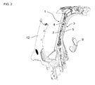
- FIG. 2 shows the view of the A-pillar structure 1 of FIG. 1 after a first mounting step has taken place.
- the mounting bracket 3 is attached to the A-pillar structure 1 via the rivets 7.
- FIG. 3 shows the view of the A-pillar structure 1 of FIG. 1 after a second mounting step has taken place.
- a trim 12 is attached to the A-pillar structure 1 covering the mounting bracket 3.
- the trim 12 comprises two recesses 13 to respectively expose the apertures 8 of the retaining portion 5 of the mounting bracket 3.
- FIG. 4 shows the view of the A-pillar structure 1 of FIG. 1 after a third mounting step has taken place.
- the grip body 9 is attached to the retaining portion 5 of the mounting bracket 3 via the bolts 10.
- FIG. 5 shows a cross sectional view along the line A-A in FIG. 4 of the A-pillar structure 1 of FIG. 1 having the grab handle 2 mounted thereon.
- the abutment flange 11 abuts on the A-pillar structure 1.
- the abutment flange 11 is welded to the attachment portion 4 of the mounting bracket 3.
- the attachment portion 4 and the retaining portion 5 of the mounting bracket 3 are formed of a single piece of sheet metal.
- the grab handle according to the present invention is used on an A-pillar structure of a motor vehicle.
Landscapes
- Engineering & Computer Science (AREA)
- Transportation (AREA)
- Mechanical Engineering (AREA)
- Passenger Equipment (AREA)
- Lock And Its Accessories (AREA)
Abstract
Description
- The present invention relates to a grab handle for a passenger compartment of a vehicle and to a motor vehicle.
- Many vehicles include one or more grab handles provided inside a passenger compartment wherein they are attached to a roof side rail of the vehicle. The grab handle provides those entering and exiting the vehicle a convenient structure to hold onto.
- It is an object of the present invention to provide an improved grab handle for a passenger compartment of a vehicle which can be manufactured and installed in vehicles with little expenditure of time and little costs. Another object of the present invention is to provide an improved motor vehicle which allows passengers to easily enter and exit a passenger compartment of the vehicle.
- These objects are achieved by a grab handle having the features of
claim 1 and by a motor vehicle having the features ofclaim 6. Further, particularly advantageous embodiments of the invention are disclosed in the respective dependent claims. - It should be noted that the individual features listed in the description below can be combined in any technically meaningful way with each other and show further embodiments of the invention. The description of the invention is additionally characterized and specified particularly in connection with the figures.
- According to the present invention a grab handle for a passenger compartment of a vehicle comprises a single mounting bracket including an attachment portion and a retaining portion. The attachment portion defines a plurality of apertures for attaching to a vehicle body member and the retaining portion defines two apertures for attaching a grip body to the mounting bracket. Furthermore, the attachment portion includes an abutment flange for abutment on said vehicle body member. This allows easy mounting of the mounting bracket to the vehicle body member as the abutment flange assures a proper alignment of the attachment portion relative to the vehicle body member. Thus, the grab handle can be mounted to the vehicle body member in a shorter time.
- According to an advantageous embodiment of the present invention the abutment flange extends substantially orthogonal to the attachment portion, thus forming substantially an L-shaped cross section of the attachment portion and the abutment flange. Hence, the attachment portion can be easily aligned with the vehicle body member.
- Another advantageous embodiment of the present invention provides that the retaining portion extends substantially orthogonal to the attachment portion, thus forming substantially an L-shaped cross section of the attachment portion and the retaining portion which results in a sturdy mounting bracket strong enough to handle forceful tugs and/or pulls by a passenger grabbing the grip body and pulling on it even in different directions.
- For an easy mounting of the grip body to the mounting bracket, according to yet another advantageous embodiment of the present invention, the grip body is attachable to the retaining portion of the mounting bracket via bolts.
- Still another advantageous embodiment of the present invention provides that at least the attachment portion and the retaining portion of the mounting bracket are formed of a single piece of sheet metal which allows fast and cost-effective manufacturing of the grab handle.
- According to another aspect of the present invention there is provided a motor vehicle comprising a grab handle according to any of the above-described embodiments.
- A particularly preferred embodiment of the present invention provides that the vehicle body member is an A-pillar structure of the vehicle.
- According to yet another advantageous embodiment of the present invention the mounting bracket is covered by a trim of the vehicle body member.
- Still another advantageous embodiment of the present invention provides that the attachment portion of the mounting bracket is fastened to the vehicle body member via rivets.
- Further features and advantages of the present invention will become apparent from the following description of a non-limiting embodiment of the invention which will be explained below with reference to the drawing. In this drawing:
- FIG. 1
- is an exploded view of an A-pillar structure of a vehicle to which an exemplary embodiment of a grab handle according to the present invention is going to be attached;
- FIG. 2
- is a view of the A-pillar structure of
FIG. 1 after a first mounting step has taken place; - FIG. 3
- is the view of the A-pillar structure of
FIG. 1 after a second mounting step has taken place; - FIG. 4
- is the view of the A-pillar structure of
FIG. 1 after a third mounting step has taken place; and - FIG. 5
- is a cross sectional view along the line A-A in
FIG. 4 of the A-pillar structure ofFIG. 1 having the grab handle mounted thereon. - In the different figures same parts are always provided with the same reference numerals so that they are generally described only once.
-
FIG. 1 is an exploded view of anA-pillar structure 1 of a vehicle to which agrab handle 2 according to an exemplary embodiment of the present invention is going to be attached. As can be observed inFIG. 1 , thegrab handle 2 comprises asingle mounting bracket 3 including anattachment portion 4 and aretaining portion 5. Theattachment portion 4 defines a plurality ofapertures 6 for attaching to theA-pillar structure 1 of the vehicle. Preferably, theattachment portion 4 is attached to theA-pillar structure 1 viarivets 7. Further, theretaining portion 5 defines twoapertures 8 for attaching agrip body 9 to saidmounting bracket 3. Preferably, thegrip body 9 is secured to the retainingportion 5 of themounting bracket 3 viabolts 10. Moreover, theattachment portion 4 of themounting bracket 3 includes anabutment flange 11 for abutment on theA-pillar structure 1. As can be seen inFIG. 1 , theabutment flange 11 extends substantially orthogonal to theattachment portion 4. Likewise, theretaining portion 5 extends substantially orthogonal to theattachment portion 4. However, theretaining portion 5 extends in a direction opposite to that of theabutment flange 11. -
FIG. 2 shows the view of theA-pillar structure 1 ofFIG. 1 after a first mounting step has taken place. In particular, inFIG. 2 , themounting bracket 3 is attached to theA-pillar structure 1 via therivets 7. -
FIG. 3 shows the view of theA-pillar structure 1 ofFIG. 1 after a second mounting step has taken place. In particular, inFIG. 3 , atrim 12 is attached to theA-pillar structure 1 covering themounting bracket 3. Thetrim 12 comprises tworecesses 13 to respectively expose theapertures 8 of theretaining portion 5 of themounting bracket 3. -
FIG. 4 shows the view of theA-pillar structure 1 ofFIG. 1 after a third mounting step has taken place. In particular, inFIG. 4 , thegrip body 9 is attached to theretaining portion 5 of themounting bracket 3 via thebolts 10. -
FIG. 5 shows a cross sectional view along the line A-A inFIG. 4 of theA-pillar structure 1 ofFIG. 1 having thegrab handle 2 mounted thereon. As is depicted inFIG. 5 , theabutment flange 11 abuts on theA-pillar structure 1. In the exemplary embodiment of thegrab handle 2 shown inFIG. 5 , theabutment flange 11 is welded to theattachment portion 4 of themounting bracket 3. Theattachment portion 4 and theretaining portion 5 of themounting bracket 3 are formed of a single piece of sheet metal. - The above-described grab handle and the motor vehicle according to the present invention are not limited to the specific embodiments disclosed herein, but also encompasses other embodiments having the same effect. It will be apparent to a skilled person in the art that various variations and modifications of the herein disclosed embodiments are possible within the spirit and scope of the present invention.
- In a preferred embodiment the grab handle according to the present invention is used on an A-pillar structure of a motor vehicle.
-
- 1
- A-pillar
- 2
- Grab handle
- 3
- Mounting bracket
- 4
- Attachment portion
- 5
- Retaining portion
- 6
- Aperture
- 7
- Rivet
- 8
- Aperture
- 9
- Grip body
- 10
- Bolt
- 11
- Abutment flange
- 12
- Trim
- 13
- Recess
Claims (9)
- A grab handle for a passenger compartment of a vehicle, comprising a single mounting bracket (3) including an attachment portion (4) and a retaining portion (5), said attachment portion (4) defining a plurality of apertures (6) for attaching to a vehicle body member (1) and said retaining portion (5) defining two apertures (8) for attaching a grip body (9) to said mounting bracket (3), wherein said attachment portion (4) includes an abutment flange (11) for abutment on said vehicle body member (1).
- The grab handle according to claim 1, wherein said abutment flange (11) extends substantially orthogonal to said attachment portion (4).
- The grab handle according to claim 1 or 2, wherein said retaining portion (5) extends substantially orthogonal to said attachment portion (4).
- The grab handle according to any of the preceding claims, wherein said grip body (9) is attachable to said retaining portion (5) of said mounting bracket (3) via bolts (10).
- The grab handle according to any of the preceding claims, wherein at least said attachment portion (4) and said retaining portion (5) of said mounting bracket (3) are formed of a single piece of sheet metal.
- A motor vehicle comprising a grab handle according to any of the preceding claims.
- The motor vehicle according to the preceding claim, wherein said vehicle body member (1) is an A-pillar structure.
- The motor vehicle according to any of the two preceding claims, wherein said mounting bracket (3) is covered by a trim (12) of said vehicle body member (1).
- The motor vehicle according to any of the three preceding claims, wherein said attachment portion (4) of said mounting bracket (3) is fastened to said vehicle body member (1) via rivets (7).
Priority Applications (2)
| Application Number | Priority Date | Filing Date | Title |
|---|---|---|---|
| TR2018/12435T TR201812435T4 (en) | 2014-03-20 | 2014-03-20 | Vehicle handle and motor vehicle. |
| EP14160904.0A EP2921346B1 (en) | 2014-03-20 | 2014-03-20 | Vehicle grab handle and motor vehicle |
Applications Claiming Priority (1)
| Application Number | Priority Date | Filing Date | Title |
|---|---|---|---|
| EP14160904.0A EP2921346B1 (en) | 2014-03-20 | 2014-03-20 | Vehicle grab handle and motor vehicle |
Publications (2)
| Publication Number | Publication Date |
|---|---|
| EP2921346A1 true EP2921346A1 (en) | 2015-09-23 |
| EP2921346B1 EP2921346B1 (en) | 2018-06-27 |
Family
ID=50289589
Family Applications (1)
| Application Number | Title | Priority Date | Filing Date |
|---|---|---|---|
| EP14160904.0A Active EP2921346B1 (en) | 2014-03-20 | 2014-03-20 | Vehicle grab handle and motor vehicle |
Country Status (2)
| Country | Link |
|---|---|
| EP (1) | EP2921346B1 (en) |
| TR (1) | TR201812435T4 (en) |
Cited By (1)
| Publication number | Priority date | Publication date | Assignee | Title |
|---|---|---|---|---|
| CN112644400A (en) * | 2020-12-29 | 2021-04-13 | 江西忻润汽车零部件有限公司 | Automobile handle decorative cover structure |
Citations (3)
| Publication number | Priority date | Publication date | Assignee | Title |
|---|---|---|---|---|
| DE19926868A1 (en) * | 1999-06-12 | 2000-11-02 | Progress Werk Oberkirch Ag | Mounting for attachment of handle in saloon of motor vehicle has fastening section and retaining section formed together in one piece as sheet metal part which has intended bend line along which retaining section is bent down |
| DE10022111A1 (en) * | 2000-05-06 | 2001-11-15 | Daimler Chrysler Ag | Grab handle for passenger compartment of vehicle has handle bracket in at least two part sectors, one for fixing to bodywork and other with handle |
| US20090091103A1 (en) * | 2007-10-09 | 2009-04-09 | Nissan Technical Center North America, Inc. | Trim panel breakaway feature |
-
2014
- 2014-03-20 EP EP14160904.0A patent/EP2921346B1/en active Active
- 2014-03-20 TR TR2018/12435T patent/TR201812435T4/en unknown
Patent Citations (3)
| Publication number | Priority date | Publication date | Assignee | Title |
|---|---|---|---|---|
| DE19926868A1 (en) * | 1999-06-12 | 2000-11-02 | Progress Werk Oberkirch Ag | Mounting for attachment of handle in saloon of motor vehicle has fastening section and retaining section formed together in one piece as sheet metal part which has intended bend line along which retaining section is bent down |
| DE10022111A1 (en) * | 2000-05-06 | 2001-11-15 | Daimler Chrysler Ag | Grab handle for passenger compartment of vehicle has handle bracket in at least two part sectors, one for fixing to bodywork and other with handle |
| US20090091103A1 (en) * | 2007-10-09 | 2009-04-09 | Nissan Technical Center North America, Inc. | Trim panel breakaway feature |
Cited By (1)
| Publication number | Priority date | Publication date | Assignee | Title |
|---|---|---|---|---|
| CN112644400A (en) * | 2020-12-29 | 2021-04-13 | 江西忻润汽车零部件有限公司 | Automobile handle decorative cover structure |
Also Published As
| Publication number | Publication date |
|---|---|
| EP2921346B1 (en) | 2018-06-27 |
| TR201812435T4 (en) | 2018-09-21 |
Similar Documents
| Publication | Publication Date | Title |
|---|---|---|
| US9415744B1 (en) | Frangible member for vehicle body structure | |
| JP6278915B2 (en) | Load transmission member | |
| SE541165C2 (en) | Fastening device for an electronic component, in particular an acceleration sensor for airbag systems | |
| JP6380779B2 (en) | Vehicle battery mounting structure | |
| EP2921346B1 (en) | Vehicle grab handle and motor vehicle | |
| WO2016076012A1 (en) | Reinforcement structure for seat belt attachment part of vehicle | |
| US8740289B2 (en) | Motor vehicle having a U-shaped bow | |
| US9630585B2 (en) | Fastening structure of side curtain airbag | |
| JP5222921B2 (en) | Diffuser device | |
| JP6102817B2 (en) | Vehicle rear structure | |
| JP5214310B2 (en) | Deck side trim mounting structure | |
| JP6367345B2 (en) | Seat belt buckle mounting structure | |
| EP3057829B1 (en) | Bus hand pole | |
| KR101458705B1 (en) | seat belt mounting bracket for automobile | |
| JP6515500B2 (en) | Center pillar of the vehicle | |
| JP2019084952A (en) | Mounting structure for interior component | |
| US20150001876A1 (en) | Secondary dash and methods of making and using the same | |
| JP6408252B2 (en) | Dive prevention device and installation method thereof | |
| JP6750428B2 (en) | Vehicle entry/exit grip mounting structure | |
| JP4737394B2 (en) | Stanchion joint material and stanchion joint structure | |
| JP2012180029A (en) | Method for mounting wind screen plate | |
| CN209126686U (en) | Seat belt securing structure and automobile including the same | |
| US10737637B2 (en) | Door cladding for a motor vehicle | |
| JP6257395B2 (en) | Vehicle front structure | |
| JP7135774B2 (en) | Mounting structure of cowl side trim |
Legal Events
| Date | Code | Title | Description |
|---|---|---|---|
| PUAI | Public reference made under article 153(3) epc to a published international application that has entered the european phase |
Free format text: ORIGINAL CODE: 0009012 |
|
| AK | Designated contracting states |
Kind code of ref document: A1 Designated state(s): AL AT BE BG CH CY CZ DE DK EE ES FI FR GB GR HR HU IE IS IT LI LT LU LV MC MK MT NL NO PL PT RO RS SE SI SK SM TR |
|
| AX | Request for extension of the european patent |
Extension state: BA ME |
|
| 17P | Request for examination filed |
Effective date: 20160323 |
|
| RBV | Designated contracting states (corrected) |
Designated state(s): AL AT BE BG CH CY CZ DE DK EE ES FI FR GB GR HR HU IE IS IT LI LT LU LV MC MK MT NL NO PL PT RO RS SE SI SK SM TR |
|
| GRAP | Despatch of communication of intention to grant a patent |
Free format text: ORIGINAL CODE: EPIDOSNIGR1 |
|
| STAA | Information on the status of an ep patent application or granted ep patent |
Free format text: STATUS: GRANT OF PATENT IS INTENDED |
|
| INTG | Intention to grant announced |
Effective date: 20180312 |
|
| GRAS | Grant fee paid |
Free format text: ORIGINAL CODE: EPIDOSNIGR3 |
|
| GRAA | (expected) grant |
Free format text: ORIGINAL CODE: 0009210 |
|
| STAA | Information on the status of an ep patent application or granted ep patent |
Free format text: STATUS: THE PATENT HAS BEEN GRANTED |
|
| AK | Designated contracting states |
Kind code of ref document: B1 Designated state(s): AL AT BE BG CH CY CZ DE DK EE ES FI FR GB GR HR HU IE IS IT LI LT LU LV MC MK MT NL NO PL PT RO RS SE SI SK SM TR |
|
| REG | Reference to a national code |
Ref country code: GB Ref legal event code: FG4D |
|
| REG | Reference to a national code |
Ref country code: AT Ref legal event code: REF Ref document number: 1012001 Country of ref document: AT Kind code of ref document: T Effective date: 20180715 |
|
| REG | Reference to a national code |
Ref country code: IE Ref legal event code: FG4D |
|
| REG | Reference to a national code |
Ref country code: DE Ref legal event code: R096 Ref document number: 602014027449 Country of ref document: DE |
|
| PG25 | Lapsed in a contracting state [announced via postgrant information from national office to epo] |
Ref country code: BG Free format text: LAPSE BECAUSE OF FAILURE TO SUBMIT A TRANSLATION OF THE DESCRIPTION OR TO PAY THE FEE WITHIN THE PRESCRIBED TIME-LIMIT Effective date: 20180927 Ref country code: FI Free format text: LAPSE BECAUSE OF FAILURE TO SUBMIT A TRANSLATION OF THE DESCRIPTION OR TO PAY THE FEE WITHIN THE PRESCRIBED TIME-LIMIT Effective date: 20180627 Ref country code: NO Free format text: LAPSE BECAUSE OF FAILURE TO SUBMIT A TRANSLATION OF THE DESCRIPTION OR TO PAY THE FEE WITHIN THE PRESCRIBED TIME-LIMIT Effective date: 20180927 Ref country code: SE Free format text: LAPSE BECAUSE OF FAILURE TO SUBMIT A TRANSLATION OF THE DESCRIPTION OR TO PAY THE FEE WITHIN THE PRESCRIBED TIME-LIMIT Effective date: 20180627 Ref country code: LT Free format text: LAPSE BECAUSE OF FAILURE TO SUBMIT A TRANSLATION OF THE DESCRIPTION OR TO PAY THE FEE WITHIN THE PRESCRIBED TIME-LIMIT Effective date: 20180627 |
|
| REG | Reference to a national code |
Ref country code: NL Ref legal event code: MP Effective date: 20180627 |
|
| REG | Reference to a national code |
Ref country code: LT Ref legal event code: MG4D |
|
| PG25 | Lapsed in a contracting state [announced via postgrant information from national office to epo] |
Ref country code: LV Free format text: LAPSE BECAUSE OF FAILURE TO SUBMIT A TRANSLATION OF THE DESCRIPTION OR TO PAY THE FEE WITHIN THE PRESCRIBED TIME-LIMIT Effective date: 20180627 Ref country code: HR Free format text: LAPSE BECAUSE OF FAILURE TO SUBMIT A TRANSLATION OF THE DESCRIPTION OR TO PAY THE FEE WITHIN THE PRESCRIBED TIME-LIMIT Effective date: 20180627 Ref country code: GR Free format text: LAPSE BECAUSE OF FAILURE TO SUBMIT A TRANSLATION OF THE DESCRIPTION OR TO PAY THE FEE WITHIN THE PRESCRIBED TIME-LIMIT Effective date: 20180928 Ref country code: RS Free format text: LAPSE BECAUSE OF FAILURE TO SUBMIT A TRANSLATION OF THE DESCRIPTION OR TO PAY THE FEE WITHIN THE PRESCRIBED TIME-LIMIT Effective date: 20180627 |
|
| REG | Reference to a national code |
Ref country code: AT Ref legal event code: MK05 Ref document number: 1012001 Country of ref document: AT Kind code of ref document: T Effective date: 20180627 |
|
| PG25 | Lapsed in a contracting state [announced via postgrant information from national office to epo] |
Ref country code: NL Free format text: LAPSE BECAUSE OF FAILURE TO SUBMIT A TRANSLATION OF THE DESCRIPTION OR TO PAY THE FEE WITHIN THE PRESCRIBED TIME-LIMIT Effective date: 20180627 |
|
| PG25 | Lapsed in a contracting state [announced via postgrant information from national office to epo] |
Ref country code: EE Free format text: LAPSE BECAUSE OF FAILURE TO SUBMIT A TRANSLATION OF THE DESCRIPTION OR TO PAY THE FEE WITHIN THE PRESCRIBED TIME-LIMIT Effective date: 20180627 Ref country code: PL Free format text: LAPSE BECAUSE OF FAILURE TO SUBMIT A TRANSLATION OF THE DESCRIPTION OR TO PAY THE FEE WITHIN THE PRESCRIBED TIME-LIMIT Effective date: 20180627 Ref country code: RO Free format text: LAPSE BECAUSE OF FAILURE TO SUBMIT A TRANSLATION OF THE DESCRIPTION OR TO PAY THE FEE WITHIN THE PRESCRIBED TIME-LIMIT Effective date: 20180627 Ref country code: IS Free format text: LAPSE BECAUSE OF FAILURE TO SUBMIT A TRANSLATION OF THE DESCRIPTION OR TO PAY THE FEE WITHIN THE PRESCRIBED TIME-LIMIT Effective date: 20181027 Ref country code: AT Free format text: LAPSE BECAUSE OF FAILURE TO SUBMIT A TRANSLATION OF THE DESCRIPTION OR TO PAY THE FEE WITHIN THE PRESCRIBED TIME-LIMIT Effective date: 20180627 Ref country code: CZ Free format text: LAPSE BECAUSE OF FAILURE TO SUBMIT A TRANSLATION OF THE DESCRIPTION OR TO PAY THE FEE WITHIN THE PRESCRIBED TIME-LIMIT Effective date: 20180627 Ref country code: SK Free format text: LAPSE BECAUSE OF FAILURE TO SUBMIT A TRANSLATION OF THE DESCRIPTION OR TO PAY THE FEE WITHIN THE PRESCRIBED TIME-LIMIT Effective date: 20180627 |
|
| PG25 | Lapsed in a contracting state [announced via postgrant information from national office to epo] |
Ref country code: SM Free format text: LAPSE BECAUSE OF FAILURE TO SUBMIT A TRANSLATION OF THE DESCRIPTION OR TO PAY THE FEE WITHIN THE PRESCRIBED TIME-LIMIT Effective date: 20180627 Ref country code: IT Free format text: LAPSE BECAUSE OF FAILURE TO SUBMIT A TRANSLATION OF THE DESCRIPTION OR TO PAY THE FEE WITHIN THE PRESCRIBED TIME-LIMIT Effective date: 20180627 Ref country code: ES Free format text: LAPSE BECAUSE OF FAILURE TO SUBMIT A TRANSLATION OF THE DESCRIPTION OR TO PAY THE FEE WITHIN THE PRESCRIBED TIME-LIMIT Effective date: 20180627 |
|
| REG | Reference to a national code |
Ref country code: DE Ref legal event code: R097 Ref document number: 602014027449 Country of ref document: DE |
|
| PLBE | No opposition filed within time limit |
Free format text: ORIGINAL CODE: 0009261 |
|
| STAA | Information on the status of an ep patent application or granted ep patent |
Free format text: STATUS: NO OPPOSITION FILED WITHIN TIME LIMIT |
|
| PG25 | Lapsed in a contracting state [announced via postgrant information from national office to epo] |
Ref country code: DK Free format text: LAPSE BECAUSE OF FAILURE TO SUBMIT A TRANSLATION OF THE DESCRIPTION OR TO PAY THE FEE WITHIN THE PRESCRIBED TIME-LIMIT Effective date: 20180627 |
|
| 26N | No opposition filed |
Effective date: 20190328 |
|
| PG25 | Lapsed in a contracting state [announced via postgrant information from national office to epo] |
Ref country code: SI Free format text: LAPSE BECAUSE OF FAILURE TO SUBMIT A TRANSLATION OF THE DESCRIPTION OR TO PAY THE FEE WITHIN THE PRESCRIBED TIME-LIMIT Effective date: 20180627 |
|
| PG25 | Lapsed in a contracting state [announced via postgrant information from national office to epo] |
Ref country code: MC Free format text: LAPSE BECAUSE OF FAILURE TO SUBMIT A TRANSLATION OF THE DESCRIPTION OR TO PAY THE FEE WITHIN THE PRESCRIBED TIME-LIMIT Effective date: 20180627 |
|
| REG | Reference to a national code |
Ref country code: CH Ref legal event code: PL |
|
| PG25 | Lapsed in a contracting state [announced via postgrant information from national office to epo] |
Ref country code: LU Free format text: LAPSE BECAUSE OF NON-PAYMENT OF DUE FEES Effective date: 20190320 Ref country code: AL Free format text: LAPSE BECAUSE OF FAILURE TO SUBMIT A TRANSLATION OF THE DESCRIPTION OR TO PAY THE FEE WITHIN THE PRESCRIBED TIME-LIMIT Effective date: 20180627 |
|
| REG | Reference to a national code |
Ref country code: BE Ref legal event code: MM Effective date: 20190331 |
|
| PG25 | Lapsed in a contracting state [announced via postgrant information from national office to epo] |
Ref country code: IE Free format text: LAPSE BECAUSE OF NON-PAYMENT OF DUE FEES Effective date: 20190320 Ref country code: CH Free format text: LAPSE BECAUSE OF NON-PAYMENT OF DUE FEES Effective date: 20190331 Ref country code: LI Free format text: LAPSE BECAUSE OF NON-PAYMENT OF DUE FEES Effective date: 20190331 |
|
| PG25 | Lapsed in a contracting state [announced via postgrant information from national office to epo] |
Ref country code: BE Free format text: LAPSE BECAUSE OF NON-PAYMENT OF DUE FEES Effective date: 20190331 |
|
| PGFP | Annual fee paid to national office [announced via postgrant information from national office to epo] |
Ref country code: GB Payment date: 20200228 Year of fee payment: 7 |
|
| PG25 | Lapsed in a contracting state [announced via postgrant information from national office to epo] |
Ref country code: PT Free format text: LAPSE BECAUSE OF FAILURE TO SUBMIT A TRANSLATION OF THE DESCRIPTION OR TO PAY THE FEE WITHIN THE PRESCRIBED TIME-LIMIT Effective date: 20181029 Ref country code: MT Free format text: LAPSE BECAUSE OF NON-PAYMENT OF DUE FEES Effective date: 20190320 |
|
| PGFP | Annual fee paid to national office [announced via postgrant information from national office to epo] |
Ref country code: FR Payment date: 20200219 Year of fee payment: 7 |
|
| PG25 | Lapsed in a contracting state [announced via postgrant information from national office to epo] |
Ref country code: CY Free format text: LAPSE BECAUSE OF FAILURE TO SUBMIT A TRANSLATION OF THE DESCRIPTION OR TO PAY THE FEE WITHIN THE PRESCRIBED TIME-LIMIT Effective date: 20180627 |
|
| PG25 | Lapsed in a contracting state [announced via postgrant information from national office to epo] |
Ref country code: HU Free format text: LAPSE BECAUSE OF FAILURE TO SUBMIT A TRANSLATION OF THE DESCRIPTION OR TO PAY THE FEE WITHIN THE PRESCRIBED TIME-LIMIT; INVALID AB INITIO Effective date: 20140320 |
|
| GBPC | Gb: european patent ceased through non-payment of renewal fee |
Effective date: 20210320 |
|
| PG25 | Lapsed in a contracting state [announced via postgrant information from national office to epo] |
Ref country code: FR Free format text: LAPSE BECAUSE OF NON-PAYMENT OF DUE FEES Effective date: 20210331 Ref country code: GB Free format text: LAPSE BECAUSE OF NON-PAYMENT OF DUE FEES Effective date: 20210320 |
|
| PG25 | Lapsed in a contracting state [announced via postgrant information from national office to epo] |
Ref country code: MK Free format text: LAPSE BECAUSE OF FAILURE TO SUBMIT A TRANSLATION OF THE DESCRIPTION OR TO PAY THE FEE WITHIN THE PRESCRIBED TIME-LIMIT Effective date: 20180627 |
|
| P01 | Opt-out of the competence of the unified patent court (upc) registered |
Effective date: 20230620 |
|
| PGFP | Annual fee paid to national office [announced via postgrant information from national office to epo] |
Ref country code: DE Payment date: 20260213 Year of fee payment: 13 |
|
| PGFP | Annual fee paid to national office [announced via postgrant information from national office to epo] |
Ref country code: TR Payment date: 20260220 Year of fee payment: 13 |