EP2921193A1 - Multiflexible catheter tube - Google Patents
Multiflexible catheter tube Download PDFInfo
- Publication number
- EP2921193A1 EP2921193A1 EP14001032.3A EP14001032A EP2921193A1 EP 2921193 A1 EP2921193 A1 EP 2921193A1 EP 14001032 A EP14001032 A EP 14001032A EP 2921193 A1 EP2921193 A1 EP 2921193A1
- Authority
- EP
- European Patent Office
- Prior art keywords
- catheter tube
- catheter
- tube
- helical cut
- inner catheter
- Prior art date
- Legal status (The legal status is an assumption and is not a legal conclusion. Google has not performed a legal analysis and makes no representation as to the accuracy of the status listed.)
- Granted
Links
Images


Classifications
-
- A—HUMAN NECESSITIES
- A61—MEDICAL OR VETERINARY SCIENCE; HYGIENE
- A61M—DEVICES FOR INTRODUCING MEDIA INTO, OR ONTO, THE BODY; DEVICES FOR TRANSDUCING BODY MEDIA OR FOR TAKING MEDIA FROM THE BODY; DEVICES FOR PRODUCING OR ENDING SLEEP OR STUPOR
- A61M25/00—Catheters; Hollow probes
- A61M25/0009—Making of catheters or other medical or surgical tubes
- A61M25/0013—Weakening parts of a catheter tubing, e.g. by making cuts in the tube or reducing thickness of a layer at one point to adjust the flexibility
-
- A—HUMAN NECESSITIES
- A61—MEDICAL OR VETERINARY SCIENCE; HYGIENE
- A61M—DEVICES FOR INTRODUCING MEDIA INTO, OR ONTO, THE BODY; DEVICES FOR TRANSDUCING BODY MEDIA OR FOR TAKING MEDIA FROM THE BODY; DEVICES FOR PRODUCING OR ENDING SLEEP OR STUPOR
- A61M25/00—Catheters; Hollow probes
- A61M25/0017—Catheters; Hollow probes specially adapted for long-term hygiene care, e.g. urethral or indwelling catheters to prevent infections
-
- A—HUMAN NECESSITIES
- A61—MEDICAL OR VETERINARY SCIENCE; HYGIENE
- A61M—DEVICES FOR INTRODUCING MEDIA INTO, OR ONTO, THE BODY; DEVICES FOR TRANSDUCING BODY MEDIA OR FOR TAKING MEDIA FROM THE BODY; DEVICES FOR PRODUCING OR ENDING SLEEP OR STUPOR
- A61M25/00—Catheters; Hollow probes
- A61M25/0043—Catheters; Hollow probes characterised by structural features
- A61M25/005—Catheters; Hollow probes characterised by structural features with embedded materials for reinforcement, e.g. wires, coils, braids
- A61M25/0051—Catheters; Hollow probes characterised by structural features with embedded materials for reinforcement, e.g. wires, coils, braids made from fenestrated or weakened tubing layer
-
- A—HUMAN NECESSITIES
- A61—MEDICAL OR VETERINARY SCIENCE; HYGIENE
- A61M—DEVICES FOR INTRODUCING MEDIA INTO, OR ONTO, THE BODY; DEVICES FOR TRANSDUCING BODY MEDIA OR FOR TAKING MEDIA FROM THE BODY; DEVICES FOR PRODUCING OR ENDING SLEEP OR STUPOR
- A61M25/00—Catheters; Hollow probes
- A61M25/0043—Catheters; Hollow probes characterised by structural features
- A61M25/0054—Catheters; Hollow probes characterised by structural features with regions for increasing flexibility
-
- A—HUMAN NECESSITIES
- A61—MEDICAL OR VETERINARY SCIENCE; HYGIENE
- A61M—DEVICES FOR INTRODUCING MEDIA INTO, OR ONTO, THE BODY; DEVICES FOR TRANSDUCING BODY MEDIA OR FOR TAKING MEDIA FROM THE BODY; DEVICES FOR PRODUCING OR ENDING SLEEP OR STUPOR
- A61M25/00—Catheters; Hollow probes
- A61M2025/0004—Catheters; Hollow probes having two or more concentrically arranged tubes for forming a concentric catheter system
Definitions
- the present invention refers to a catheter with an inner catheter tube and an outer catheter tube which tightly surrounds the inner catheter tube.
- the present invention also refers to a method for producing such a catheter.
- Catheters are long tubular devices used for insertion into body lumens, for example, the urethra. However, other catheter types, for example epidural catheters, may also be introduced through solid tissue. Catheters generally include at least one passageway over their length.
- the catheter As catheters are guided through body lumens, it is generally desirable that the catheter is flexible to follow the tortuous body lumen and to reduce trauma. Furthermore, the catheter must also possess sufficient strength or rigidity so that it can be pushed through the body lumen. Catheters will typically be advanced by pushing them manually forward so that the advancement force is transmitted axially along the length of the catheter. In order to transmit this force without kinking or buckling, the catheter must possess sufficient column strength to resist the compressive forces of advancement.
- Such a catheter is for example known from document US 5,947,940 .
- This document discloses a strong, thin walled, highly flexible catheter comprising an outer tubular cover and at least one helical reinforcing member which is inserted in the outer cover.
- the helical reinforcing member consists of a stiff band which is helically wound to form the helical reinforcing member. Therefore, between the single turns of the helical reinforcing member, gaps exist.
- the helical reinforcing band is wound upon a core which is subsequently removed. After that, the outer tubular layer is applied by extrusion or die-coating.
- the inner catheter tube is provided with a helical cut. Due to the helical cut, the inner catheter tube is easily bendable and can therefore be easily introduced in a tortuous body lumen, for example the urethra, but still has sufficient stiffness in its longitudinal direction to insert and push the catheter forward. When pushing the catheter forward, the parts of the inner catheter tube separated by the helical cut abut each other and the force in the axial or forward direction is transmitted and transformed in a forward movement of the catheter.
- the outer catheter tube which surrounds the inner catheter tube ensures the impermeability of the catheter and provides a continuous outer surface of the catheter.
- the helical cut completely penetrates the wall of the inner catheter tube. Therefore, the depth of the helical cut corresponds to at least the wall thickness of the inner catheter tube. When the cut completely separates the wall, good bending properties and good pushability is achieved.
- the inner catheter tube is made of a stiffer material than the outer catheter tube.
- the inner catheter tube then provides the stiffness in radial and axial direction which is necessary for pushing the catheter forward and for avoiding kinking of the catheter but still has a high bendability due to the helical cut whereas the outer catheter tube ensures the impermeability and low friction of the catheter.
- the pitch of the helical cut varies along the length of the inner catheter tube. Therefore, the stiffness and the bending radius of the catheter vary along the length of the catheter.
- the helical cut In the tip region of the catheter, that is the region of the catheter which is first inserted in the body lumen, the helical cut has a small pitch so that the single turns of the helical cut lay close together. This leads to a small bending radius and a relatively low stiffness in this region. In the other regions of the catheter the pitch - and therewith the bending radius - can be larger and the catheter is stiffer.
- distal end of the inner catheter tube is provided with the helical cut.
- the distal end of the catheter then has the desired bendability whereas the proximal part of the catheter tube can be used as a handle and improves the pushability and handling of the catheter.
- distal means the part of the catheter which is directed towards a user's body when introducing the catheter
- proximal refers to the other end of the catheter.
- the catheter is a urinary catheter for the introduction in the human urethra with a catheter tube comprising the inner catheter tube with the helical cut and the outer catheter tube which tightly surrounds the inner catheter tube.
- This urinary catheter can be used for intermittent self-catheterisation by handicapped users and is very easy in handling and can be easily inserted without causing harm to the urethra.
- the outer catheter tube comprises a hydrophilic coating at least along its insertable length. This coating further reduces friction when introducing the catheter into a body lumen.
- the inner catheter tube and the outer catheter tube may be transparent.
- the catheter tubes then provide a visual indication, of fluid presence and movement within the catheter, for example.
- the inner catheter tube and the outer catheter tube may be non-metallic providing a MRI compatible catheter.
- the inner and outer catheter tubes may contain holes for fluid introduction or removal through the catheter.
- the tensile performance of the catheter may be improved with the addition of a longitudinal reinforcement such as fibres provided between the inner catheter tube and the outer catheter tube or within the outer catheter tube.
- the pressure differential on the outer catheter tube is applied via the injection of a pressurized fluid, for example air or water. Therefore, only harmless ingredients are used for the manufacturing so that special safety precautions, which are necessary when handling for example solvents, can be avoided.
- the pressure applied on the outer catheter tube lies in a range of 5 to 30 bar. This leads to a sufficient increase in the inner diameter of the outer catheter tube. However, the pressure force is not strong enough to damage the outer catheter tube.
- the outer catheter tube is inserted in a cylindrical housing before the internal pressure is applied. This leads to a uniform inflation of the outer catheter tube so that any "ballooning effect", wherein some regions of the catheter tube are larger than others, is avoided.
- the outer tube length may be managed throughout the assembly process therefore providing an additional compression or tension between the inner and outer tube in the formed catheter. It is for example possible to apply tension to the outer catheter tube during inflation so the tube is stretched. Due to the stretching in the longitudinal direction, the outer catheter tube compresses the inner catheter tube with the helical cut and therefore influences the behaviour of the assembled, finished catheter.
- the outer catheter tube is over-moulded on the inner catheter tube and encapsulates at least the region of the inner catheter tube which is provided with the helical cut.
- the over-moulding can be profiled to create a smooth crossing-profile of the device and can comprise surface apertures to facilitate fluid transfer to and from the inner catheter tube. Pending on the over-moulding material and the material of the inner catheter tube, the inner catheter tube with the helical cut can be adhered to the over-moulded outer catheter tube or not.
- FIG. 1 shows a urinary catheter 1 according to the present invention.
- the urinary catheter 1 comprises a catheter tube 2 which is provided at one end with a catheter tip 3 with at least one eyelet or opening 17 and the other end with a funnel 4.
- the catheter 1 defines an internal passageway which extends from the catheter tip 3 to the other end of the catheter 1 with the funnel 4. Through this passageway, liquid can be inserted through the funnel 4 and the tip 3 into a body lumen or can be drained from a body lumen through the catheter tip 3, the internal passageway and the other end with the funnel 4 out of the body.
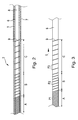
- FIG 2 shows a cross section through the catheter tube 2 as shown in Figure 1 .
- the catheter tube 2 comprises an outer catheter tube 5 and an inner catheter tube 6.
- the outer catheter tube 5 forms the outer surface 7 of the catheter tube 2.
- the inner catheter tube 6 defines the internal passageway 8 of the catheter.
- the inner catheter tube 6 is provided with a helical cut 9.
- the helical cut 9 does not extend over the complete length of the catheter tube 2 but is only provided along the insertable length of the catheter tube 2.
- the term "insertable length" defines the length of the catheter tube which is intended and adapted for the insertion into a body lumen.
- the helical cut 9 has different pitches.
- the pitch of the helical cut 9 is small.
- the pitch of the helical cut 9 is increased and is even larger in the following region C. Therefore, the inner catheter tube 6 has a different bendability and a different bending radius along its length.
- the pitch of the helical cut may also be kept constant along a part or the entire length of the inner catheter tube.
- the helical cut 9 as shown in Figure 2 extends completely through the wall of the inner catheter tube 6. This means that the depth of the helical cut is at least as large as the thickness of the wall of the inner catheter tube 6.
- the inner catheter tube 6 and the outer catheter tube 5 are made of different materials.
- the material of the inner catheter tube 6 is stiffer than the material of the outer catheter tube 5.
- the inner catheter tube 6 can, for example, be made of polyethylene or nylon, the outer catheter tube 5 can be made of polyurethane.
- the inner catheter tube 6 therefore has a higher stiffness than the outer catheter tube and transmits the axial forces acting along the length of the catheter 1 when introducing the catheter in a body lumen.
- the catheter 1 can thus be easily inserted in the body lumen.
- As the inner catheter tube 6 is provided with a helical cut 9 and not with a helical groove, adjacent parts of the inner catheter tube 6 which are separated by the helical cut 9 still abut at each other and there is no space between them. Therefore, the axial forces can be transmitted without compressing the inner catheter tube 6.
- the inner catheter tube and the outer catheter tube are preferably made of non-metallic material, preferably plastics, the catheter is MRI-compatible.
- the material of the outer catheter tube 5 is softer than the material of the inner catheter tube 6.
- the outer catheter tube 5 tightly surrounds the inner catheter tube 6 and therefore leads to a liquid impermeable catheter tube. Due to the soft material used for the outer catheter tube 5, the bending properties of the catheter 1 and the catheter tube 2 are not affected and the whole catheter 1 can easily be inserted along the tortuous body lumen. Furthermore, the coefficient of friction of the outer catheter tube 5 is preferably very small.
- the outer catheter tube can be coated with a hydrophilic coating. This helps to easily introduce the 1 catheter into a body lumen. No harm or trauma to the body lumen is caused.
- Figure 3 shows a part of the inner catheter tube 6.
- the helical cut 9 which extends along the length L of the catheter tube can be clearly seen.
- the helical cut 9 In the front region A of the inner catheter tube 6, which is the region which is at first introduced into the body lumen, the helical cut 9 has a first pitch P1.
- the helical cut 9 In the following region B of the inner catheter tube, the helical cut 9 has a second pitch P2.
- pitch P2 is twice as large as pitch P1.
- the helical cut 9 has a third pitch P3.
- Pitch P3 is approximately twice as large as pitch P2. Therefore, the tip region of the catheter has a very small bending radius which allows insertion of the tip for example in the bladder of a user.
- the bending radius of the catheter 1 and the stiffness of the catheter 1 increase. Furthermore, the stiffness of the catheter 1 can be fine-tuned at the interface of the regions A and B and at the interface of the regions B and C by the introduction of a transient pitch region creating a gradual increase in pitch, i.e. from pitch P2 to pitch P3.
- FIG 4 shows another embodiment of a urinary catheter 1' according to the present invention and a diagram showing the change of the flexural stiffness of the catheter 1' along the catheter length L.
- the urinary catheter 1' basically corresponds to the urinary catheter as described above. In the following, only the differences are disclosed.
- the outer catheter tube 5 is shown in cross section; the inner catheter tube 6' is not cut.
- the urinary catheter 1' comprises an outer catheter tube 5 and an inner catheter tube 6'.
- the inner catheter tube 6' is provided with a helical cut 9'.
- the helical cut 9' extends only along the distal section D of the catheter 1' which is arranged near the catheter tip 3.
- the inner catheter tube 6' is not slotted or cut.
- the inner catheter tube 6' ends shortly before the catheter tip 3.
- the catheter tip 3 is provided with an eyelet 17.
- the pitch P of the helical cut 9' varies along the length L of the urinary catheter 1' Near the tip 3 of the urinary catheter 1', the pitch P of the helical cut 9' is very small and increases in the direction towards the proximal end of the urinary catheter 1'. Preferably, the pitch P increases continuously.
- the stiffness of the urinary catheter 1' varies along the catheter length L.
- the stiffness is on a constant high level.
- the stiffness of the urinary catheter 1' decreases until it reaches a minimum value at the catheter tip 3.
- FIG 5 shows a further embodiment of a urinary catheter 1".
- the urinary catheter 1" as shown in Figure 5 basically corresponds to the other embodiments as described above. In the following, only the differences are described.
- the urinary catheter 1" comprises an outer catheter tube 5" and an inner catheter tube 6".
- the inner catheter tube 6" comprises a helical cut 9" at its front end or distal end which is closest to the catheter tip 3.
- the helical cut 9" does not extend over the complete length of the urinary catheter 1 ".
- the pitch of the helical cut 9" is constant.
- the outer catheter tube 5" is over-moulded on the outer catheter tube 6".
- the outer catheter tube 5" does not extend along the complete length of the catheter 1" but only encapsulates the part of the inner catheter tube 6" which is provided with the helical cut 9". Furthermore, the outer catheter tube 5" extends to the distal end of the urinary catheter 1" and forms the catheter tip 3 as well as the eyelet 17. In this tip region, the urinary catheter 1" is not provided with an inner catheter tube. It is also possible that the outer catheter tube is a component that is positioned and attached to the inner catheter tube so that it at least encapsulates the helical cut section of the inner catheter tube.
- the outer catheter tube which can be over-moulded or an attached component, is preferably profiled to create a smooth outer surface on the urinary catheter. Depending on the material of the attached component or on the over-moulding material and the material of the inner catheter tube, the inner catheter tube with the helical cut may be adhered to the outer catheter tube or not.
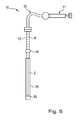
- Figure 6 shows a device 10 for producing the catheter 1 as described above.
- the device 10 comprises an apparatus 11 for pressurizing a fluid, a tube 12 which connects the apparatus 11 to a holding mechanism for holding the outer catheter tube 5, an insertion mechanism 13 for holding and inserting the inner catheter tube 6, a cylindrical housing 15 and an end cap 16 for tightly closing the outer end of the outer catheter tube 5.
- the outer catheter tube 5 made of a soft material is placed on the holder 14.
- the free end of the outer catheter tube 5 is closed with the end cap 16 so that the outer catheter tube 5 forms a closed system together with the holder 14 and the end cap 16.
- the cylindrical housing 15 is placed around the outer catheter tube 5.
- the inner catheter tube 6 with the helical cut 9 is inserted in the insertion mechanism 13.
- the outer catheter tube 5 is then connected via the holder 14, the insertion mechanism 13, and the tube 12 with the pressure apparatus 11 in a fluid tight manner.
- a pressurized fluid for example air or water, which is pressurized via the pressure apparatus 11, is injected in the outer catheter tube 5 so that an internal pressure or a pressure differential is applied on the outer catheter tube 5.
- a pressurized fluid for example air or water, which is pressurized via the pressure apparatus 11
- the inner catheter tube 6 with the helical cut 9 is inserted in the expanded outer catheter tube 5 via the insertion mechanism 13.
- the pressure applied on the outer catheter tube 5 is released and the outer catheter tube 5 contracts and tightly surrounds the inner catheter tube 6.
- the pressure applied on the outer catheter tube 5 preferably lies in a range from 5 to 30 bar. In this range, the increase in inner diameter of the outer catheter tube 5 is sufficient to insert the inner catheter tube 6, however, the outer catheter tube 5 is not harmed and still contracts after the release of the pressure.
- This range of pressure is the optimal range for a urinary catheter. However, for other catheter designs or other applications, for example micro-catheter assemblies or larger diameter devices, other ranges of pressure are desirable.
- the reinforced catheter tube 2 with the inner catheter tube 6 and the outer catheter tube 5 produced as described above can then be used for manufacturing catheters.
- the catheter 1" as described above can be produced by over-moulding the inner catheter tube 6" at least in the region where it is provided with the helical cut 9" with a second, softer material to produce the outer catheter tube 5".
- the catheters as described above comprising an inner catheter tube with a helical cut and an outer catheter tube tightly surrounding the inner catheter tube can be used in a variety of catheter types. Apart from urinary catheters, epidural catheters, introducers and introducer guide catheters are often reinforced.
- All catheters as described above may comprise transparent inner and outer catheter tubes so that a visual indication for example for fluid presence or movement within the catheter is provided.
- the inner catheter tube and the outer catheter tube may contain holes for fluid introduction or removal through the catheter.
- the catheters can be provided with a longitudinal reinforcement such as fibres provided between the inner catheter tube and the outer catheter tube or within the outer catheter tube. In this case, the tensile performance of the catheter is improved.
Abstract
Description
- The present invention refers to a catheter with an inner catheter tube and an outer catheter tube which tightly surrounds the inner catheter tube.
- Furthermore, the present invention also refers to a method for producing such a catheter.
- Catheters are long tubular devices used for insertion into body lumens, for example, the urethra. However, other catheter types, for example epidural catheters, may also be introduced through solid tissue. Catheters generally include at least one passageway over their length.
- As catheters are guided through body lumens, it is generally desirable that the catheter is flexible to follow the tortuous body lumen and to reduce trauma. Furthermore, the catheter must also possess sufficient strength or rigidity so that it can be pushed through the body lumen. Catheters will typically be advanced by pushing them manually forward so that the advancement force is transmitted axially along the length of the catheter. In order to transmit this force without kinking or buckling, the catheter must possess sufficient column strength to resist the compressive forces of advancement.
- Such a catheter is for example known from document
US 5,947,940 . This document discloses a strong, thin walled, highly flexible catheter comprising an outer tubular cover and at least one helical reinforcing member which is inserted in the outer cover. The helical reinforcing member consists of a stiff band which is helically wound to form the helical reinforcing member. Therefore, between the single turns of the helical reinforcing member, gaps exist. For producing the catheter, the helical reinforcing band is wound upon a core which is subsequently removed. After that, the outer tubular layer is applied by extrusion or die-coating. - It is the object of the present invention to provide a reinforced catheter and a method for producing this catheter which overcome at least partially the disadvantages of the devices and methods known so far and which can be easily introduced in a body lumen and has nevertheless a good kinking resistance and pushability and can be easily manufactured.
- For this purpose, the inner catheter tube is provided with a helical cut. Due to the helical cut, the inner catheter tube is easily bendable and can therefore be easily introduced in a tortuous body lumen, for example the urethra, but still has sufficient stiffness in its longitudinal direction to insert and push the catheter forward. When pushing the catheter forward, the parts of the inner catheter tube separated by the helical cut abut each other and the force in the axial or forward direction is transmitted and transformed in a forward movement of the catheter. The outer catheter tube which surrounds the inner catheter tube ensures the impermeability of the catheter and provides a continuous outer surface of the catheter.
- Furthermore, it can be provided that the helical cut completely penetrates the wall of the inner catheter tube. Therefore, the depth of the helical cut corresponds to at least the wall thickness of the inner catheter tube. When the cut completely separates the wall, good bending properties and good pushability is achieved.
- In an advantageous embodiment it can be provided that the inner catheter tube is made of a stiffer material than the outer catheter tube. The inner catheter tube then provides the stiffness in radial and axial direction which is necessary for pushing the catheter forward and for avoiding kinking of the catheter but still has a high bendability due to the helical cut whereas the outer catheter tube ensures the impermeability and low friction of the catheter.
- In a further embodiment it can be provided that the pitch of the helical cut varies along the length of the inner catheter tube. Therefore, the stiffness and the bending radius of the catheter vary along the length of the catheter. In the tip region of the catheter, that is the region of the catheter which is first inserted in the body lumen, the helical cut has a small pitch so that the single turns of the helical cut lay close together. This leads to a small bending radius and a relatively low stiffness in this region. In the other regions of the catheter the pitch - and therewith the bending radius - can be larger and the catheter is stiffer.
- It can further be provided that only the distal end of the inner catheter tube is provided with the helical cut. The distal end of the catheter then has the desired bendability whereas the proximal part of the catheter tube can be used as a handle and improves the pushability and handling of the catheter. In this context the term "distal" means the part of the catheter which is directed towards a user's body when introducing the catheter, the term "proximal" refers to the other end of the catheter.
- In still another embodiment it can be provided that the catheter is a urinary catheter for the introduction in the human urethra with a catheter tube comprising the inner catheter tube with the helical cut and the outer catheter tube which tightly surrounds the inner catheter tube. This urinary catheter can be used for intermittent self-catheterisation by handicapped users and is very easy in handling and can be easily inserted without causing harm to the urethra.
- Preferably, the outer catheter tube comprises a hydrophilic coating at least along its insertable length. This coating further reduces friction when introducing the catheter into a body lumen.
- In another embodiment the inner catheter tube and the outer catheter tube may be transparent. The catheter tubes then provide a visual indication, of fluid presence and movement within the catheter, for example.
- In another embodiment the inner catheter tube and the outer catheter tube may be non-metallic providing a MRI compatible catheter.
- In yet another embodiment the inner and outer catheter tubes may contain holes for fluid introduction or removal through the catheter.
- In another embodiment the tensile performance of the catheter may be improved with the addition of a longitudinal reinforcement such as fibres provided between the inner catheter tube and the outer catheter tube or within the outer catheter tube.
- Furthermore, the above mentioned object is also solved by a method for producing a catheter as described above and comprising the following steps:
- Applying a pressure differential between the inside and the outside of the outer catheter tube so that its internal diameter is enlarged,
- Inserting the inner catheter tube with the helical cut in the enlarged outer catheter tube,
- Releasing the pressure differential so that the outer catheter tube contracts and tightly surrounds the inner catheter tube.
- Commonly known methods for producing reinforced catheters such as over extrusion and dip coating can be difficult to control and often require long periods of time for the soft outer catheter tube to stabilize. The present method offers a safe and easy manufacturing method and leads to a product that can be immediately packed and shipped.
- In a variant of the method, it can be provided that the pressure differential on the outer catheter tube is applied via the injection of a pressurized fluid, for example air or water. Therefore, only harmless ingredients are used for the manufacturing so that special safety precautions, which are necessary when handling for example solvents, can be avoided.
- Furthermore, it can be provided that the pressure applied on the outer catheter tube lies in a range of 5 to 30 bar. This leads to a sufficient increase in the inner diameter of the outer catheter tube. However, the pressure force is not strong enough to damage the outer catheter tube.
- In still another variant of the method, the outer catheter tube is inserted in a cylindrical housing before the internal pressure is applied. This leads to a uniform inflation of the outer catheter tube so that any "ballooning effect", wherein some regions of the catheter tube are larger than others, is avoided.
- In addition to the use of a pressure differential, the outer tube length may be managed throughout the assembly process therefore providing an additional compression or tension between the inner and outer tube in the formed catheter. It is for example possible to apply tension to the outer catheter tube during inflation so the tube is stretched. Due to the stretching in the longitudinal direction, the outer catheter tube compresses the inner catheter tube with the helical cut and therefore influences the behaviour of the assembled, finished catheter.
- In another very easy method for producing a catheter as described above, the outer catheter tube is over-moulded on the inner catheter tube and encapsulates at least the region of the inner catheter tube which is provided with the helical cut. The over-moulding can be profiled to create a smooth crossing-profile of the device and can comprise surface apertures to facilitate fluid transfer to and from the inner catheter tube. Pending on the over-moulding material and the material of the inner catheter tube, the inner catheter tube with the helical cut can be adhered to the over-moulded outer catheter tube or not.
- In the following, the invention is described in more detail with the aid of drawings:
-
Figure 1 shows a urinary catheter according to the present invention, -
Figure 2 shows a cross section of the catheter tube of the catheter shown inFigure 1 , -
Figure 3 shows the inner catheter tube of the catheter inFigures 1 and2 , -
Figure 4 shows the stiffness of a catheter along its longitudinal direction, -
Figure 5 shows another embodiment of the urinary catheter and -
Figure 6 shows a device for manufacturing the catheter ofFigures 1 to 3 . -
Figure 1 shows aurinary catheter 1 according to the present invention. Theurinary catheter 1 comprises acatheter tube 2 which is provided at one end with acatheter tip 3 with at least one eyelet oropening 17 and the other end with afunnel 4. Thecatheter 1 defines an internal passageway which extends from thecatheter tip 3 to the other end of thecatheter 1 with thefunnel 4. Through this passageway, liquid can be inserted through thefunnel 4 and thetip 3 into a body lumen or can be drained from a body lumen through thecatheter tip 3, the internal passageway and the other end with thefunnel 4 out of the body. -
Figure 2 shows a cross section through thecatheter tube 2 as shown inFigure 1 . Thecatheter tube 2 comprises anouter catheter tube 5 and aninner catheter tube 6. Theouter catheter tube 5 forms theouter surface 7 of thecatheter tube 2. Theinner catheter tube 6 defines theinternal passageway 8 of the catheter. Theinner catheter tube 6 is provided with ahelical cut 9. InFigure 2 , thehelical cut 9 does not extend over the complete length of thecatheter tube 2 but is only provided along the insertable length of thecatheter tube 2. The term "insertable length" defines the length of the catheter tube which is intended and adapted for the insertion into a body lumen. - In
Figure 2 , thehelical cut 9 has different pitches. In the front region A, the pitch of thehelical cut 9 is small. In the following region B, the pitch of thehelical cut 9 is increased and is even larger in the following region C. Therefore, theinner catheter tube 6 has a different bendability and a different bending radius along its length. However, the pitch of the helical cut may also be kept constant along a part or the entire length of the inner catheter tube. - The
helical cut 9 as shown inFigure 2 extends completely through the wall of theinner catheter tube 6. This means that the depth of the helical cut is at least as large as the thickness of the wall of theinner catheter tube 6. - The
inner catheter tube 6 and theouter catheter tube 5 are made of different materials. The material of theinner catheter tube 6 is stiffer than the material of theouter catheter tube 5. Theinner catheter tube 6 can, for example, be made of polyethylene or nylon, theouter catheter tube 5 can be made of polyurethane. Theinner catheter tube 6 therefore has a higher stiffness than the outer catheter tube and transmits the axial forces acting along the length of thecatheter 1 when introducing the catheter in a body lumen. Thecatheter 1 can thus be easily inserted in the body lumen. As theinner catheter tube 6 is provided with ahelical cut 9 and not with a helical groove, adjacent parts of theinner catheter tube 6 which are separated by thehelical cut 9 still abut at each other and there is no space between them. Therefore, the axial forces can be transmitted without compressing theinner catheter tube 6. As both catheter tubes, the inner catheter tube and the outer catheter tube, are preferably made of non-metallic material, preferably plastics, the catheter is MRI-compatible. - The material of the
outer catheter tube 5 is softer than the material of theinner catheter tube 6. Theouter catheter tube 5 tightly surrounds theinner catheter tube 6 and therefore leads to a liquid impermeable catheter tube. Due to the soft material used for theouter catheter tube 5, the bending properties of thecatheter 1 and thecatheter tube 2 are not affected and thewhole catheter 1 can easily be inserted along the tortuous body lumen. Furthermore, the coefficient of friction of theouter catheter tube 5 is preferably very small. For example, the outer catheter tube can be coated with a hydrophilic coating. This helps to easily introduce the 1 catheter into a body lumen. No harm or trauma to the body lumen is caused. -
Figure 3 shows a part of theinner catheter tube 6. Thehelical cut 9 which extends along the length L of the catheter tube can be clearly seen. In the front region A of theinner catheter tube 6, which is the region which is at first introduced into the body lumen, thehelical cut 9 has a first pitch P1. In the following region B of the inner catheter tube, thehelical cut 9 has a second pitch P2. In the example shown, pitch P2 is twice as large as pitch P1. In the region C which follows region B, thehelical cut 9 has a third pitch P3. Pitch P3 is approximately twice as large as pitch P2. Therefore, the tip region of the catheter has a very small bending radius which allows insertion of the tip for example in the bladder of a user. In the following regions, the bending radius of thecatheter 1 and the stiffness of thecatheter 1 increase. Furthermore, the stiffness of thecatheter 1 can be fine-tuned at the interface of the regions A and B and at the interface of the regions B and C by the introduction of a transient pitch region creating a gradual increase in pitch, i.e. from pitch P2 to pitch P3. -
Figure 4 shows another embodiment of a urinary catheter 1' according to the present invention and a diagram showing the change of the flexural stiffness of the catheter 1' along the catheter length L. The urinary catheter 1' basically corresponds to the urinary catheter as described above. In the following, only the differences are disclosed. InFigure 4 , only the front part of the urinary catheter 1' is shown, theouter catheter tube 5 is shown in cross section; the inner catheter tube 6' is not cut. The urinary catheter 1' comprises anouter catheter tube 5 and an inner catheter tube 6'. The inner catheter tube 6' is provided with a helical cut 9'. The helical cut 9' extends only along the distal section D of the catheter 1' which is arranged near thecatheter tip 3. In the remaining or proximal part E of the urinary catheter 1' the inner catheter tube 6' is not slotted or cut. The inner catheter tube 6' ends shortly before thecatheter tip 3. Thecatheter tip 3 is provided with aneyelet 17. The pitch P of the helical cut 9' varies along the length L of the urinary catheter 1' Near thetip 3 of the urinary catheter 1', the pitch P of the helical cut 9' is very small and increases in the direction towards the proximal end of the urinary catheter 1'. Preferably, the pitch P increases continuously. As shown in the diagram above the urinary catheter 1' with thegraph 18, the stiffness of the urinary catheter 1' varies along the catheter length L. In the proximal region E, where the inner catheter tube 6' is not provided with a helical cut, the stiffness is on a constant high level. In the region D of the inner catheter tube 6' with the helical cut 9' the stiffness of the urinary catheter 1' decreases until it reaches a minimum value at thecatheter tip 3. -
Figure 5 shows a further embodiment of aurinary catheter 1". Theurinary catheter 1" as shown inFigure 5 basically corresponds to the other embodiments as described above. In the following, only the differences are described. Theurinary catheter 1" comprises anouter catheter tube 5" and aninner catheter tube 6". Theinner catheter tube 6" comprises ahelical cut 9" at its front end or distal end which is closest to thecatheter tip 3. Thehelical cut 9" does not extend over the complete length of theurinary catheter 1 ". Furthermore, the pitch of thehelical cut 9" is constant. Theouter catheter tube 5" is over-moulded on theouter catheter tube 6". Theouter catheter tube 5" does not extend along the complete length of thecatheter 1" but only encapsulates the part of theinner catheter tube 6" which is provided with thehelical cut 9". Furthermore, theouter catheter tube 5" extends to the distal end of theurinary catheter 1" and forms thecatheter tip 3 as well as theeyelet 17. In this tip region, theurinary catheter 1" is not provided with an inner catheter tube. It is also possible that the outer catheter tube is a component that is positioned and attached to the inner catheter tube so that it at least encapsulates the helical cut section of the inner catheter tube. The outer catheter tube, which can be over-moulded or an attached component, is preferably profiled to create a smooth outer surface on the urinary catheter. Depending on the material of the attached component or on the over-moulding material and the material of the inner catheter tube, the inner catheter tube with the helical cut may be adhered to the outer catheter tube or not. -
Figure 6 shows adevice 10 for producing thecatheter 1 as described above. Thedevice 10 comprises anapparatus 11 for pressurizing a fluid, atube 12 which connects theapparatus 11 to a holding mechanism for holding theouter catheter tube 5, aninsertion mechanism 13 for holding and inserting theinner catheter tube 6, acylindrical housing 15 and anend cap 16 for tightly closing the outer end of theouter catheter tube 5. - In the following, the method for producing the catheter is described with the aid of
Figure 6 . Theouter catheter tube 5 made of a soft material is placed on theholder 14. The free end of theouter catheter tube 5 is closed with theend cap 16 so that theouter catheter tube 5 forms a closed system together with theholder 14 and theend cap 16. Then, thecylindrical housing 15 is placed around theouter catheter tube 5. Theinner catheter tube 6 with thehelical cut 9 is inserted in theinsertion mechanism 13. Theouter catheter tube 5 is then connected via theholder 14, theinsertion mechanism 13, and thetube 12 with thepressure apparatus 11 in a fluid tight manner. In the next step, a pressurized fluid, for example air or water, which is pressurized via thepressure apparatus 11, is injected in theouter catheter tube 5 so that an internal pressure or a pressure differential is applied on theouter catheter tube 5. This leads to an increase of the inner diameter of theouter catheter tube 5. Then, theinner catheter tube 6 with thehelical cut 9 is inserted in the expandedouter catheter tube 5 via theinsertion mechanism 13. When theinner catheter tube 6 is completely inserted in theouter catheter tube 5, the pressure applied on theouter catheter tube 5 is released and theouter catheter tube 5 contracts and tightly surrounds theinner catheter tube 6. - The pressure applied on the
outer catheter tube 5 preferably lies in a range from 5 to 30 bar. In this range, the increase in inner diameter of theouter catheter tube 5 is sufficient to insert theinner catheter tube 6, however, theouter catheter tube 5 is not harmed and still contracts after the release of the pressure. This range of pressure is the optimal range for a urinary catheter. However, for other catheter designs or other applications, for example micro-catheter assemblies or larger diameter devices, other ranges of pressure are desirable. The reinforcedcatheter tube 2 with theinner catheter tube 6 and theouter catheter tube 5 produced as described above can then be used for manufacturing catheters. - In another simple embodiment for the manufacturing method, the
catheter 1" as described above can be produced by over-moulding theinner catheter tube 6" at least in the region where it is provided with thehelical cut 9" with a second, softer material to produce theouter catheter tube 5". - The catheters as described above comprising an inner catheter tube with a helical cut and an outer catheter tube tightly surrounding the inner catheter tube can be used in a variety of catheter types. Apart from urinary catheters, epidural catheters, introducers and introducer guide catheters are often reinforced.
- All catheters as described above may comprise transparent inner and outer catheter tubes so that a visual indication for example for fluid presence or movement within the catheter is provided. Furthermore, the inner catheter tube and the outer catheter tube may contain holes for fluid introduction or removal through the catheter. The catheters can be provided with a longitudinal reinforcement such as fibres provided between the inner catheter tube and the outer catheter tube or within the outer catheter tube. In this case, the tensile performance of the catheter is improved.
-
- 1; 1'; 1"
- Urinary catheter
- 2; 2"
- Catheter tube
- 3
- Catheter tip
- 4
- Funnel
- 5; 5"
- Outer catheter tube
- 6; 6'; 6"
- Inner catheter tube
- 7
- Outer surface catheter tube
- 8
- Internal passageway
- 9; 9'; 9"
- Helical cut
- 10
- Manufacturing device
- 11
- Pressure apparatus
- 12
- Tube
- 13
- Insertion mechanism
- 14
- Holding mechanism
- 15
- Cylindrical housing
- 16
- End cap
- 17
- Eyelet
- 18
- Graph
- L
- Longitudinal direction of the catheter
- P
- Pitch of helical cut
- P1
- First pitch
- P2
- Second pitch
- P3
- Third pitch
- A; B; C; D; E
- Regions of the catheter
Claims (15)
- Catheter (1; 1'; 1") with an inner catheter tube (6; 6'; 6") and an outer catheter tube (5; 5") which tightly surrounds the inner catheter tube (6; 6'; 6"), characterized in that the inner catheter tube (6; 6'; 6") is provided with a helical cut (9; 9'; 9").
- Catheter according to claim 1, characterized in that the helical cut (9; 9'; 9") completely penetrates the wall of the inner catheter tube (6; 6'; 6").
- Catheter according to claims 1 or 2, characterized in that the inner catheter tube (6; 6'; 6") is made of a stiffer material than the outer catheter tube (5; 5").
- Catheter according to at least one of claims 1 to 3, characterized in that the pitch of the helical cut (9; 9') varies along the length of the inner catheter tube (6; 6').
- Catheter according to at least one of claims 1 to 4, characterized in that only the distal end of the inner catheter tube (6; 6'; 6") is provided with the helical cut (9; 9'; 9").
- Catheter according to at least one of claims 1 to 5, characterized in that the catheter is a urinary catheter for the introduction in the human urethra with a catheter tube (2) comprising the inner catheter tube (6; 6'; 6") with the helical cut (9; 9'; 9"), and the outer catheter tube (5; 5") which tightly surrounds the inner catheter tube (6; 6'; 6").
- Catheter according to any of the preceding claims, characterized in that the outer catheter tube (5; 5") comprises a hydrophilic coating at least along its insertable length.
- Catheter according to any of the preceding claims, characterized in that the inner catheter tube (5; 5") and the outer catheter tube (6; 6'; 6") are transparent.
- Catheter according to any of the preceding claims, characterized in that the inner catheter tube (5; 5") and the outer catheter tube (6; 6'; 6") are non-metallic.
- Catheter according to any of the preceding claims, characterized in that the catheter (1; 1'; 1") comprises a longitudinal reinforcement.
- Method for producing a catheter (1) according to any of the claims 1 to 10,
characterized by the following steps:• Applying a pressure differential between the inside and the outside of the outer catheter tube (5) so that its internal diameter is enlarged,• Inserting the inner catheter tube (6) with the helical cut (9) in the enlarged outer catheter tube (5),• Releasing the pressure differential so that the outer catheter tube (5) contracts and tightly surrounds the inner catheter tube (6). - Method according to claim 11, characterized in that the pressure differential on the outer catheter tube (5; 5") is applied via the injection of a pressurized fluid, for example air or water.
- Method according to claim 11 or 12, characterized in that the pressure differential applied on the outer catheter tube (5) lies in a range of 5 to 30 bar.
- Method according to at least one of claims 11 to 13, characterized in that the outer catheter tube (5) is inserted in a cylindrical housing (15) before the pressure differential is applied.
- Method for producing a catheter (1") according to any of the claims 1 to 10 characterized in that the outer catheter tube (5") is over-moulded on the inner catheter tube (6") and encapsulates at least the region of the inner catheter tube (6") which is provided with the helical cut (9").
Priority Applications (1)
| Application Number | Priority Date | Filing Date | Title |
|---|---|---|---|
| EP14001032.3A EP2921193B1 (en) | 2014-03-20 | 2014-03-20 | Multiflexible catheter tube |
Applications Claiming Priority (1)
| Application Number | Priority Date | Filing Date | Title |
|---|---|---|---|
| EP14001032.3A EP2921193B1 (en) | 2014-03-20 | 2014-03-20 | Multiflexible catheter tube |
Publications (2)
| Publication Number | Publication Date |
|---|---|
| EP2921193A1 true EP2921193A1 (en) | 2015-09-23 |
| EP2921193B1 EP2921193B1 (en) | 2019-08-21 |
Family
ID=50349415
Family Applications (1)
| Application Number | Title | Priority Date | Filing Date |
|---|---|---|---|
| EP14001032.3A Active EP2921193B1 (en) | 2014-03-20 | 2014-03-20 | Multiflexible catheter tube |
Country Status (1)
| Country | Link |
|---|---|
| EP (1) | EP2921193B1 (en) |
Cited By (2)
| Publication number | Priority date | Publication date | Assignee | Title |
|---|---|---|---|---|
| CN109464738A (en) * | 2018-12-21 | 2019-03-15 | 尚楠 | A kind of catheter and Male urethral catheter |
| WO2022221509A1 (en) * | 2021-04-16 | 2022-10-20 | Hollister Incorporated | Urinary catheter with patterned drainage holes to provide tip flexibility |
Citations (10)
| Publication number | Priority date | Publication date | Assignee | Title |
|---|---|---|---|---|
| WO1994001160A1 (en) * | 1992-07-14 | 1994-01-20 | Arrow International Investment Corporation | Unibody construction dual durometer epidural catheter |
| US5573520A (en) * | 1991-09-05 | 1996-11-12 | Mayo Foundation For Medical Education And Research | Flexible tubular device for use in medical applications |
| WO1997032623A1 (en) * | 1996-03-07 | 1997-09-12 | Heartport, Inc. | Cannula and method of manufacture and use |
| US5947940A (en) | 1997-06-23 | 1999-09-07 | Beisel; Robert F. | Catheter reinforced to prevent luminal collapse and tensile failure thereof |
| US20050049545A1 (en) * | 2003-09-02 | 2005-03-03 | Scimed Life Systems, Inc. | Construction of medical components using gas assisted microcellular foaming |
| US20060084939A1 (en) * | 2004-10-20 | 2006-04-20 | Lentz David J | Articulation segment for a catheter |
| WO2007028058A2 (en) * | 2005-09-02 | 2007-03-08 | Boston Scientific Limited | Adjustable stiffness catheter |
| US20070066900A1 (en) * | 2005-09-22 | 2007-03-22 | Boston Scientific Scimed, Inc. | Intravascular ultrasound catheter |
| WO2010080715A1 (en) * | 2009-01-12 | 2010-07-15 | Becton, Dickinson And Company | Infusion set and/or patch pump having at least one of an in-dwelling rigid catheter with flexible features and/or a flexible catheter attachment |
| EP2364746A1 (en) * | 2010-03-12 | 2011-09-14 | Terumo Kabushiki Kaisha | Catheter |
-
2014
- 2014-03-20 EP EP14001032.3A patent/EP2921193B1/en active Active
Patent Citations (10)
| Publication number | Priority date | Publication date | Assignee | Title |
|---|---|---|---|---|
| US5573520A (en) * | 1991-09-05 | 1996-11-12 | Mayo Foundation For Medical Education And Research | Flexible tubular device for use in medical applications |
| WO1994001160A1 (en) * | 1992-07-14 | 1994-01-20 | Arrow International Investment Corporation | Unibody construction dual durometer epidural catheter |
| WO1997032623A1 (en) * | 1996-03-07 | 1997-09-12 | Heartport, Inc. | Cannula and method of manufacture and use |
| US5947940A (en) | 1997-06-23 | 1999-09-07 | Beisel; Robert F. | Catheter reinforced to prevent luminal collapse and tensile failure thereof |
| US20050049545A1 (en) * | 2003-09-02 | 2005-03-03 | Scimed Life Systems, Inc. | Construction of medical components using gas assisted microcellular foaming |
| US20060084939A1 (en) * | 2004-10-20 | 2006-04-20 | Lentz David J | Articulation segment for a catheter |
| WO2007028058A2 (en) * | 2005-09-02 | 2007-03-08 | Boston Scientific Limited | Adjustable stiffness catheter |
| US20070066900A1 (en) * | 2005-09-22 | 2007-03-22 | Boston Scientific Scimed, Inc. | Intravascular ultrasound catheter |
| WO2010080715A1 (en) * | 2009-01-12 | 2010-07-15 | Becton, Dickinson And Company | Infusion set and/or patch pump having at least one of an in-dwelling rigid catheter with flexible features and/or a flexible catheter attachment |
| EP2364746A1 (en) * | 2010-03-12 | 2011-09-14 | Terumo Kabushiki Kaisha | Catheter |
Cited By (2)
| Publication number | Priority date | Publication date | Assignee | Title |
|---|---|---|---|---|
| CN109464738A (en) * | 2018-12-21 | 2019-03-15 | 尚楠 | A kind of catheter and Male urethral catheter |
| WO2022221509A1 (en) * | 2021-04-16 | 2022-10-20 | Hollister Incorporated | Urinary catheter with patterned drainage holes to provide tip flexibility |
Also Published As
| Publication number | Publication date |
|---|---|
| EP2921193B1 (en) | 2019-08-21 |
Similar Documents
| Publication | Publication Date | Title |
|---|---|---|
| US6102890A (en) | Catheter having improved proximal shaft design | |
| US8821510B2 (en) | Flexible sheath with polymer coil | |
| US8715441B2 (en) | Medical tubing having variable characteristics and method of making same | |
| US6045734A (en) | Process of making a catheter | |
| US6022343A (en) | Bridged coil catheter support structure | |
| CA1309633C (en) | Guiding catheter with controllable distal tip | |
| US10780247B2 (en) | Catheter structure with improved support and related systems, methods, and devices | |
| EP0637453B1 (en) | Method for manufacturing a catheter with at least one high-pressure lumen and catheter | |
| EP3013404B1 (en) | Introducer sheath for radial artery access | |
| CN106102814B (en) | Catheter tube | |
| US20070276354A1 (en) | Introducer Sheath and Method for Making | |
| US20080146999A1 (en) | Balloon cover | |
| EP2921193A1 (en) | Multiflexible catheter tube | |
| AU2013207571B2 (en) | Medical tubing | |
| US20030093060A1 (en) | Catheter assembly | |
| EP1212185A1 (en) | Introducer device having variable flexibility and kink resistance and method of manufacture of same | |
| JP4765130B2 (en) | Catheter and method of manufacturing the same | |
| EP3328476B1 (en) | Coronary guide catheter | |
| US20070073310A1 (en) | Method for joining medical devices | |
| US11260200B1 (en) | Catheters and methods for making them | |
| US9061116B2 (en) | Introducer assembly and sheath therefor | |
| NZ808071A (en) | Expandable Introducer Sheath for Medical Device |
Legal Events
| Date | Code | Title | Description |
|---|---|---|---|
| PUAI | Public reference made under article 153(3) epc to a published international application that has entered the european phase |
Free format text: ORIGINAL CODE: 0009012 |
|
| AK | Designated contracting states |
Kind code of ref document: A1 Designated state(s): AL AT BE BG CH CY CZ DE DK EE ES FI FR GB GR HR HU IE IS IT LI LT LU LV MC MK MT NL NO PL PT RO RS SE SI SK SM TR |
|
| AX | Request for extension of the european patent |
Extension state: BA ME |
|
| 17P | Request for examination filed |
Effective date: 20160323 |
|
| RBV | Designated contracting states (corrected) |
Designated state(s): AL AT BE BG CH CY CZ DE DK EE ES FI FR GB GR HR HU IE IS IT LI LT LU LV MC MK MT NL NO PL PT RO RS SE SI SK SM TR |
|
| STAA | Information on the status of an ep patent application or granted ep patent |
Free format text: STATUS: EXAMINATION IS IN PROGRESS |
|
| 17Q | First examination report despatched |
Effective date: 20181025 |
|
| GRAP | Despatch of communication of intention to grant a patent |
Free format text: ORIGINAL CODE: EPIDOSNIGR1 |
|
| STAA | Information on the status of an ep patent application or granted ep patent |
Free format text: STATUS: GRANT OF PATENT IS INTENDED |
|
| GRAJ | Information related to disapproval of communication of intention to grant by the applicant or resumption of examination proceedings by the epo deleted |
Free format text: ORIGINAL CODE: EPIDOSDIGR1 |
|
| STAA | Information on the status of an ep patent application or granted ep patent |
Free format text: STATUS: EXAMINATION IS IN PROGRESS |
|
| INTG | Intention to grant announced |
Effective date: 20190313 |
|
| INTC | Intention to grant announced (deleted) | ||
| GRAP | Despatch of communication of intention to grant a patent |
Free format text: ORIGINAL CODE: EPIDOSNIGR1 |
|
| STAA | Information on the status of an ep patent application or granted ep patent |
Free format text: STATUS: GRANT OF PATENT IS INTENDED |
|
| INTG | Intention to grant announced |
Effective date: 20190509 |
|
| GRAS | Grant fee paid |
Free format text: ORIGINAL CODE: EPIDOSNIGR3 |
|
| GRAA | (expected) grant |
Free format text: ORIGINAL CODE: 0009210 |
|
| STAA | Information on the status of an ep patent application or granted ep patent |
Free format text: STATUS: THE PATENT HAS BEEN GRANTED |
|
| AK | Designated contracting states |
Kind code of ref document: B1 Designated state(s): AL AT BE BG CH CY CZ DE DK EE ES FI FR GB GR HR HU IE IS IT LI LT LU LV MC MK MT NL NO PL PT RO RS SE SI SK SM TR |
|
| REG | Reference to a national code |
Ref country code: GB Ref legal event code: FG4D |
|
| REG | Reference to a national code |
Ref country code: CH Ref legal event code: EP |
|
| REG | Reference to a national code |
Ref country code: DE Ref legal event code: R096 Ref document number: 602014052013 Country of ref document: DE |
|
| REG | Reference to a national code |
Ref country code: AT Ref legal event code: REF Ref document number: 1169008 Country of ref document: AT Kind code of ref document: T Effective date: 20190915 |
|
| REG | Reference to a national code |
Ref country code: IE Ref legal event code: FG4D |
|
| REG | Reference to a national code |
Ref country code: LT Ref legal event code: MG4D |
|
| REG | Reference to a national code |
Ref country code: NL Ref legal event code: MP Effective date: 20190821 |
|
| PG25 | Lapsed in a contracting state [announced via postgrant information from national office to epo] |
Ref country code: LT Free format text: LAPSE BECAUSE OF FAILURE TO SUBMIT A TRANSLATION OF THE DESCRIPTION OR TO PAY THE FEE WITHIN THE PRESCRIBED TIME-LIMIT Effective date: 20190821 Ref country code: SE Free format text: LAPSE BECAUSE OF FAILURE TO SUBMIT A TRANSLATION OF THE DESCRIPTION OR TO PAY THE FEE WITHIN THE PRESCRIBED TIME-LIMIT Effective date: 20190821 Ref country code: BG Free format text: LAPSE BECAUSE OF FAILURE TO SUBMIT A TRANSLATION OF THE DESCRIPTION OR TO PAY THE FEE WITHIN THE PRESCRIBED TIME-LIMIT Effective date: 20191121 Ref country code: NL Free format text: LAPSE BECAUSE OF FAILURE TO SUBMIT A TRANSLATION OF THE DESCRIPTION OR TO PAY THE FEE WITHIN THE PRESCRIBED TIME-LIMIT Effective date: 20190821 Ref country code: HR Free format text: LAPSE BECAUSE OF FAILURE TO SUBMIT A TRANSLATION OF THE DESCRIPTION OR TO PAY THE FEE WITHIN THE PRESCRIBED TIME-LIMIT Effective date: 20190821 Ref country code: PT Free format text: LAPSE BECAUSE OF FAILURE TO SUBMIT A TRANSLATION OF THE DESCRIPTION OR TO PAY THE FEE WITHIN THE PRESCRIBED TIME-LIMIT Effective date: 20191223 Ref country code: FI Free format text: LAPSE BECAUSE OF FAILURE TO SUBMIT A TRANSLATION OF THE DESCRIPTION OR TO PAY THE FEE WITHIN THE PRESCRIBED TIME-LIMIT Effective date: 20190821 Ref country code: NO Free format text: LAPSE BECAUSE OF FAILURE TO SUBMIT A TRANSLATION OF THE DESCRIPTION OR TO PAY THE FEE WITHIN THE PRESCRIBED TIME-LIMIT Effective date: 20191121 |
|
| PG25 | Lapsed in a contracting state [announced via postgrant information from national office to epo] |
Ref country code: RS Free format text: LAPSE BECAUSE OF FAILURE TO SUBMIT A TRANSLATION OF THE DESCRIPTION OR TO PAY THE FEE WITHIN THE PRESCRIBED TIME-LIMIT Effective date: 20190821 Ref country code: IS Free format text: LAPSE BECAUSE OF FAILURE TO SUBMIT A TRANSLATION OF THE DESCRIPTION OR TO PAY THE FEE WITHIN THE PRESCRIBED TIME-LIMIT Effective date: 20191221 Ref country code: ES Free format text: LAPSE BECAUSE OF FAILURE TO SUBMIT A TRANSLATION OF THE DESCRIPTION OR TO PAY THE FEE WITHIN THE PRESCRIBED TIME-LIMIT Effective date: 20190821 Ref country code: LV Free format text: LAPSE BECAUSE OF FAILURE TO SUBMIT A TRANSLATION OF THE DESCRIPTION OR TO PAY THE FEE WITHIN THE PRESCRIBED TIME-LIMIT Effective date: 20190821 Ref country code: GR Free format text: LAPSE BECAUSE OF FAILURE TO SUBMIT A TRANSLATION OF THE DESCRIPTION OR TO PAY THE FEE WITHIN THE PRESCRIBED TIME-LIMIT Effective date: 20191122 Ref country code: AL Free format text: LAPSE BECAUSE OF FAILURE TO SUBMIT A TRANSLATION OF THE DESCRIPTION OR TO PAY THE FEE WITHIN THE PRESCRIBED TIME-LIMIT Effective date: 20190821 |
|
| REG | Reference to a national code |
Ref country code: AT Ref legal event code: MK05 Ref document number: 1169008 Country of ref document: AT Kind code of ref document: T Effective date: 20190821 |
|
| PG25 | Lapsed in a contracting state [announced via postgrant information from national office to epo] |
Ref country code: TR Free format text: LAPSE BECAUSE OF FAILURE TO SUBMIT A TRANSLATION OF THE DESCRIPTION OR TO PAY THE FEE WITHIN THE PRESCRIBED TIME-LIMIT Effective date: 20190821 |
|
| PG25 | Lapsed in a contracting state [announced via postgrant information from national office to epo] |
Ref country code: DK Free format text: LAPSE BECAUSE OF FAILURE TO SUBMIT A TRANSLATION OF THE DESCRIPTION OR TO PAY THE FEE WITHIN THE PRESCRIBED TIME-LIMIT Effective date: 20190821 Ref country code: AT Free format text: LAPSE BECAUSE OF FAILURE TO SUBMIT A TRANSLATION OF THE DESCRIPTION OR TO PAY THE FEE WITHIN THE PRESCRIBED TIME-LIMIT Effective date: 20190821 Ref country code: PL Free format text: LAPSE BECAUSE OF FAILURE TO SUBMIT A TRANSLATION OF THE DESCRIPTION OR TO PAY THE FEE WITHIN THE PRESCRIBED TIME-LIMIT Effective date: 20190821 Ref country code: EE Free format text: LAPSE BECAUSE OF FAILURE TO SUBMIT A TRANSLATION OF THE DESCRIPTION OR TO PAY THE FEE WITHIN THE PRESCRIBED TIME-LIMIT Effective date: 20190821 Ref country code: RO Free format text: LAPSE BECAUSE OF FAILURE TO SUBMIT A TRANSLATION OF THE DESCRIPTION OR TO PAY THE FEE WITHIN THE PRESCRIBED TIME-LIMIT Effective date: 20190821 |
|
| PG25 | Lapsed in a contracting state [announced via postgrant information from national office to epo] |
Ref country code: SM Free format text: LAPSE BECAUSE OF FAILURE TO SUBMIT A TRANSLATION OF THE DESCRIPTION OR TO PAY THE FEE WITHIN THE PRESCRIBED TIME-LIMIT Effective date: 20190821 Ref country code: SK Free format text: LAPSE BECAUSE OF FAILURE TO SUBMIT A TRANSLATION OF THE DESCRIPTION OR TO PAY THE FEE WITHIN THE PRESCRIBED TIME-LIMIT Effective date: 20190821 Ref country code: IS Free format text: LAPSE BECAUSE OF FAILURE TO SUBMIT A TRANSLATION OF THE DESCRIPTION OR TO PAY THE FEE WITHIN THE PRESCRIBED TIME-LIMIT Effective date: 20200224 Ref country code: CZ Free format text: LAPSE BECAUSE OF FAILURE TO SUBMIT A TRANSLATION OF THE DESCRIPTION OR TO PAY THE FEE WITHIN THE PRESCRIBED TIME-LIMIT Effective date: 20190821 |
|
| REG | Reference to a national code |
Ref country code: DE Ref legal event code: R097 Ref document number: 602014052013 Country of ref document: DE |
|
| PLBE | No opposition filed within time limit |
Free format text: ORIGINAL CODE: 0009261 |
|
| STAA | Information on the status of an ep patent application or granted ep patent |
Free format text: STATUS: NO OPPOSITION FILED WITHIN TIME LIMIT |
|
| PG2D | Information on lapse in contracting state deleted |
Ref country code: IS |
|
| 26N | No opposition filed |
Effective date: 20200603 |
|
| PG25 | Lapsed in a contracting state [announced via postgrant information from national office to epo] |
Ref country code: SI Free format text: LAPSE BECAUSE OF FAILURE TO SUBMIT A TRANSLATION OF THE DESCRIPTION OR TO PAY THE FEE WITHIN THE PRESCRIBED TIME-LIMIT Effective date: 20190821 |
|
| PG25 | Lapsed in a contracting state [announced via postgrant information from national office to epo] |
Ref country code: MC Free format text: LAPSE BECAUSE OF FAILURE TO SUBMIT A TRANSLATION OF THE DESCRIPTION OR TO PAY THE FEE WITHIN THE PRESCRIBED TIME-LIMIT Effective date: 20190821 |
|
| REG | Reference to a national code |
Ref country code: CH Ref legal event code: PL |
|
| REG | Reference to a national code |
Ref country code: BE Ref legal event code: MM Effective date: 20200331 |
|
| PG25 | Lapsed in a contracting state [announced via postgrant information from national office to epo] |
Ref country code: LU Free format text: LAPSE BECAUSE OF NON-PAYMENT OF DUE FEES Effective date: 20200320 |
|
| PG25 | Lapsed in a contracting state [announced via postgrant information from national office to epo] |
Ref country code: CH Free format text: LAPSE BECAUSE OF NON-PAYMENT OF DUE FEES Effective date: 20200331 Ref country code: LI Free format text: LAPSE BECAUSE OF NON-PAYMENT OF DUE FEES Effective date: 20200331 Ref country code: IE Free format text: LAPSE BECAUSE OF NON-PAYMENT OF DUE FEES Effective date: 20200320 |
|
| PG25 | Lapsed in a contracting state [announced via postgrant information from national office to epo] |
Ref country code: BE Free format text: LAPSE BECAUSE OF NON-PAYMENT OF DUE FEES Effective date: 20200331 |
|
| PG25 | Lapsed in a contracting state [announced via postgrant information from national office to epo] |
Ref country code: MT Free format text: LAPSE BECAUSE OF FAILURE TO SUBMIT A TRANSLATION OF THE DESCRIPTION OR TO PAY THE FEE WITHIN THE PRESCRIBED TIME-LIMIT Effective date: 20190821 Ref country code: CY Free format text: LAPSE BECAUSE OF FAILURE TO SUBMIT A TRANSLATION OF THE DESCRIPTION OR TO PAY THE FEE WITHIN THE PRESCRIBED TIME-LIMIT Effective date: 20190821 |
|
| PG25 | Lapsed in a contracting state [announced via postgrant information from national office to epo] |
Ref country code: MK Free format text: LAPSE BECAUSE OF FAILURE TO SUBMIT A TRANSLATION OF THE DESCRIPTION OR TO PAY THE FEE WITHIN THE PRESCRIBED TIME-LIMIT Effective date: 20190821 |
|
| PGFP | Annual fee paid to national office [announced via postgrant information from national office to epo] |
Ref country code: FR Payment date: 20230322 Year of fee payment: 10 |
|
| PGFP | Annual fee paid to national office [announced via postgrant information from national office to epo] |
Ref country code: GB Payment date: 20230322 Year of fee payment: 10 Ref country code: DE Payment date: 20230323 Year of fee payment: 10 |
|
| PGFP | Annual fee paid to national office [announced via postgrant information from national office to epo] |
Ref country code: IT Payment date: 20230331 Year of fee payment: 10 |