EP2921189B1 - Initalization of a dosing unit for drug infusion - Google Patents
Initalization of a dosing unit for drug infusion Download PDFInfo
- Publication number
- EP2921189B1 EP2921189B1 EP14160177.3A EP14160177A EP2921189B1 EP 2921189 B1 EP2921189 B1 EP 2921189B1 EP 14160177 A EP14160177 A EP 14160177A EP 2921189 B1 EP2921189 B1 EP 2921189B1
- Authority
- EP
- European Patent Office
- Prior art keywords
- dosing
- dosing chamber
- volume
- valve
- priming
- Prior art date
- Legal status (The legal status is an assumption and is not a legal conclusion. Google has not performed a legal analysis and makes no representation as to the accuracy of the status listed.)
- Active
Links
Images


Classifications
-
- A—HUMAN NECESSITIES
- A61—MEDICAL OR VETERINARY SCIENCE; HYGIENE
- A61M—DEVICES FOR INTRODUCING MEDIA INTO, OR ONTO, THE BODY; DEVICES FOR TRANSDUCING BODY MEDIA OR FOR TAKING MEDIA FROM THE BODY; DEVICES FOR PRODUCING OR ENDING SLEEP OR STUPOR
- A61M5/00—Devices for bringing media into the body in a subcutaneous, intra-vascular or intramuscular way; Accessories therefor, e.g. filling or cleaning devices, arm-rests
- A61M5/14—Infusion devices, e.g. infusing by gravity; Blood infusion; Accessories therefor
- A61M5/142—Pressure infusion, e.g. using pumps
- A61M5/14244—Pressure infusion, e.g. using pumps adapted to be carried by the patient, e.g. portable on the body
-
- A—HUMAN NECESSITIES
- A61—MEDICAL OR VETERINARY SCIENCE; HYGIENE
- A61M—DEVICES FOR INTRODUCING MEDIA INTO, OR ONTO, THE BODY; DEVICES FOR TRANSDUCING BODY MEDIA OR FOR TAKING MEDIA FROM THE BODY; DEVICES FOR PRODUCING OR ENDING SLEEP OR STUPOR
- A61M5/00—Devices for bringing media into the body in a subcutaneous, intra-vascular or intramuscular way; Accessories therefor, e.g. filling or cleaning devices, arm-rests
- A61M5/14—Infusion devices, e.g. infusing by gravity; Blood infusion; Accessories therefor
- A61M5/142—Pressure infusion, e.g. using pumps
- A61M5/14212—Pumping with an aspiration and an expulsion action
- A61M5/14216—Reciprocating piston type
-
- A—HUMAN NECESSITIES
- A61—MEDICAL OR VETERINARY SCIENCE; HYGIENE
- A61M—DEVICES FOR INTRODUCING MEDIA INTO, OR ONTO, THE BODY; DEVICES FOR TRANSDUCING BODY MEDIA OR FOR TAKING MEDIA FROM THE BODY; DEVICES FOR PRODUCING OR ENDING SLEEP OR STUPOR
- A61M5/00—Devices for bringing media into the body in a subcutaneous, intra-vascular or intramuscular way; Accessories therefor, e.g. filling or cleaning devices, arm-rests
- A61M5/36—Devices for bringing media into the body in a subcutaneous, intra-vascular or intramuscular way; Accessories therefor, e.g. filling or cleaning devices, arm-rests with means for eliminating or preventing injection or infusion of air into body
-
- A—HUMAN NECESSITIES
- A61—MEDICAL OR VETERINARY SCIENCE; HYGIENE
- A61M—DEVICES FOR INTRODUCING MEDIA INTO, OR ONTO, THE BODY; DEVICES FOR TRANSDUCING BODY MEDIA OR FOR TAKING MEDIA FROM THE BODY; DEVICES FOR PRODUCING OR ENDING SLEEP OR STUPOR
- A61M5/00—Devices for bringing media into the body in a subcutaneous, intra-vascular or intramuscular way; Accessories therefor, e.g. filling or cleaning devices, arm-rests
- A61M5/14—Infusion devices, e.g. infusing by gravity; Blood infusion; Accessories therefor
- A61M2005/1401—Functional features
- A61M2005/1402—Priming
-
- A—HUMAN NECESSITIES
- A61—MEDICAL OR VETERINARY SCIENCE; HYGIENE
- A61M—DEVICES FOR INTRODUCING MEDIA INTO, OR ONTO, THE BODY; DEVICES FOR TRANSDUCING BODY MEDIA OR FOR TAKING MEDIA FROM THE BODY; DEVICES FOR PRODUCING OR ENDING SLEEP OR STUPOR
- A61M2205/00—General characteristics of the apparatus
- A61M2205/10—General characteristics of the apparatus with powered movement mechanisms
- A61M2205/103—General characteristics of the apparatus with powered movement mechanisms rotating
-
- A—HUMAN NECESSITIES
- A61—MEDICAL OR VETERINARY SCIENCE; HYGIENE
- A61M—DEVICES FOR INTRODUCING MEDIA INTO, OR ONTO, THE BODY; DEVICES FOR TRANSDUCING BODY MEDIA OR FOR TAKING MEDIA FROM THE BODY; DEVICES FOR PRODUCING OR ENDING SLEEP OR STUPOR
- A61M2205/00—General characteristics of the apparatus
- A61M2205/33—Controlling, regulating or measuring
- A61M2205/3331—Pressure; Flow
-
- A—HUMAN NECESSITIES
- A61—MEDICAL OR VETERINARY SCIENCE; HYGIENE
- A61M—DEVICES FOR INTRODUCING MEDIA INTO, OR ONTO, THE BODY; DEVICES FOR TRANSDUCING BODY MEDIA OR FOR TAKING MEDIA FROM THE BODY; DEVICES FOR PRODUCING OR ENDING SLEEP OR STUPOR
- A61M2205/00—General characteristics of the apparatus
- A61M2205/70—General characteristics of the apparatus with testing or calibration facilities
- A61M2205/702—General characteristics of the apparatus with testing or calibration facilities automatically during use
Definitions
- a major critical aspect and issue of concern with respect to ambulatory infusion systems that include a dedicated dosing unit is the handling of gas, in particular air, in the fluid path. While it would be generally desirable to provide a drug reservoir completely filled with liquid drug, e.g. a liquid insulin formulation, and without any air, this is hardly achievable under the circumstances that are typically given for ambulatory infusion systems and with reasonable costs and handling effort. In addition, outgassing of air that is initially solved in the liquid drug is known to occur during application, e.g. due to temperature variations. Furthermore, the dosing unit is, in contrast to the classical syringe driver design, not integral with the drug reservoir but fluidically coupled with the drug reservoir via a fluidic reservoir coupling conduit that is also filled with air in the supply state. Air may further be drawn into the dosing chamber in case of a faulty or improperly coupled fluidic connection.
- gas in particular air
- the first priming routine further includes the step closing the filling valve and opening the draining valve.
- the first priming routine further includes emptying the dosing unit by decreasing the dosing chamber volume to the minimal dosing chamber volume. Thereby, the mixture of liquid and air/gas is expelled via the draining valve.
- the minimal dosing chamber volume is negligible or zero.
- V 0 being the design-given fluidic volume of the reservoir coupling conduit
- p ref being a reference pressure, in particular an surrounding environmental pressure
- V s being a safety margin volume.
- control unit is further designed for controlling, prior to controlling execution of the first priming routine, execution of a sensor calibration routine by:
- the draining valve 205 is opened with the filling valve 204 staying closed. Thereby, the compressed gas is partly expelled out of the dosing chamber via the draining valve until the pressure inside the dosing chamber equals the environmental pressure.
- the dosing chamber volume is further decreased to the minimal dosing chamber volume by displacing the piston in the proximal direction. Thereby, the dosing cylinder 101 is emptied and the remaining gas is expelled out of the dosing chamber 202.
- the dosing chamber volume is increased by the first priming volume v 1 , which is achieved by displacing the piston 201 into the distal direction.
- the dosing chamber corresponds a mixture of air and gas in dependence of the reservoir fluid pressure p 2 .
- the reservoir coupling conduit is in any case filled with liquid drug.
- the dosing chamber volume is increased by a second priming volume v 2 , which is achieved by displacing the piston 102 into the distal direction.
- a second priming volume v 2 results in sucking a second priming amount of liquid drug reservoir 10 into the dosing chamber.
- the second priming amount of liquid drug may be identical to the second priming volume v 2 if no air/gas is suck from the liquid drug reservoir; otherwise, the second priming amount of liquid drug is smaller than the second priming volume v 2 and a the dosing chamber is filled with a mixture of liquid drug and air/gas at the end of step S121.
- step S125a If the dosing chamber pressure p C is positive, the dosing chamber volume is increased in the step S125a by displacing the piston 201 by an incremental step in the distal direction, thereby decreasing the positive chamber pressure p C .
- step S126a it is determined, by reading and evaluating the output value of the pressure sensor 203, if the dosing chamber pressure p C equals the reference pressure p ref . If this is the case, the operational flow proceeds with step the S127. Otherwise, the operational flow proceeds with repeating the step S125a.
- the dosing chamber volume is decreased by displacing the piston 201 by an incremental step in the proximal direction.
- the chamber pressure p C is measured by reading and evaluating the output value of the pressure sensor 203.
Landscapes
- Health & Medical Sciences (AREA)
- Vascular Medicine (AREA)
- Engineering & Computer Science (AREA)
- Anesthesiology (AREA)
- Biomedical Technology (AREA)
- Heart & Thoracic Surgery (AREA)
- Hematology (AREA)
- Life Sciences & Earth Sciences (AREA)
- Animal Behavior & Ethology (AREA)
- General Health & Medical Sciences (AREA)
- Public Health (AREA)
- Veterinary Medicine (AREA)
- Emergency Medicine (AREA)
- Infusion, Injection, And Reservoir Apparatuses (AREA)
Description
- The present invention relates to a method for initializing a dosing unit of an ambulatory infusion system, to a control unit for controlling operation of a dosing unit of an ambulatory infusion system, and to an ambulatory infusion device.
- Ambulatory infusion devices are well known in the art for example in the therapy of Diabetes Mellitus by Continuous Subcutaneous Insulin Infusion (CSII) as well as in pain therapy or cancer therapy and are available from a number of suppliers, such as Roche Diagnostics GmbH, Germany, or Medtronic MiniMed Inc., CA, USA.
- According to a classic and well-established design, those ambulatory infusion devices are typically of the syringe-driver type. A number of drawbacks of such devices are known in the art. In particular, they have a limited precision because they involve delivering very small drug amounts, typically in the Nanoliter range, out of a drug cartridge having an overall drug volume in the millilitre range. Therefore, additional concepts and architectures have been proposed which use a dedicated dosing unit downstream from the drug reservoir. Such a dosing unit comprises a miniaturized pump, e.g., a micro membrane pump or a micro piston pump. It is adapted to couple to a liquid drug reservoir and is further especially designed for precise dosing of small volumes in the small Microliter range or Nanoliter range. While several designs for such dosing units are known in the art, they are rather complex, most of them are expensive and/or critical with respect to large scale.
- The
EP1970677A1 discloses a system with a miniaturized piston pump as dosing unit. This dosing unit includes a dosing cylinder that is repeatedly coupled to and filled from a larger reservoir, followed by coupling the dosing cylinder to an infusion line and infusing the liquid drug out of the dosing cylinder in incremental steps and over an extended time period. For alternatively coupling the dosing cylinder to the reservoir and the infusion line, a valve system is proposed. - For illustrative purposes, reference is made to
Figure 1 , showing an exemplary dosing unit according to the disclosure ofEP1970677A1 in a schematic structural view. The dosing unit includes a dosing cylinder (also referred to as "pump cylinder") 2 with a dosing chamber 6 that may be varied in steps or increments by displacing a dosing piston (also simply referred to as "piston") 3. The dosing cylinder 2 may have a single opening or aperture 2a for filling the variable dosing chamber with drug via asupply tube 4 orreservoir coupling conduit 4 from a drug container and expelling drug from the variable dosing volume into a catheter orinfusion line 5. The aperture 2a that is arranged in a proximal wall section of the dosing cylinder 2 may - by rotating the dosing cylinder 2, about its longitudinal axis with respect to a sealing stationary member (not referenced, U-shaped piece inFigure 1 ) -be alternatively a alternatively aligned with a reservoir coupling port or an outlet port, thereby alternatively coupling the dosing chamber 6 with thereservoir coupling conduit 4 or theinfusion line 5. The pump cylinder and the stationary member, in combination, accordingly form a valve arrangement with a filling valve for coupling with thereservoir coupling conduit 4 and a draining valve for coupling with the catheter. Depending on the rotational position of the dosing cylinder either of the filling valve or the draining valve may be opened, with the other valve being closed. In an intermediate state, both the filling valve and the draining valve are closed. Simultaneous opening of the filling valve and the draining valve is prevented by the design of the valve arrangement. The process of filling the dosing chamber may also be referred to as "charging" and the process of expelling drug out of the dosing chamber as "discharging". The filling valve may accordingly be referred to as "charging valve" and the draining valve may be referred to as "discharging valve". - A major critical aspect and issue of concern with respect to ambulatory infusion systems that include a dedicated dosing unit is the handling of gas, in particular air, in the fluid path. While it would be generally desirable to provide a drug reservoir completely filled with liquid drug, e.g. a liquid insulin formulation, and without any air, this is hardly achievable under the circumstances that are typically given for ambulatory infusion systems and with reasonable costs and handling effort. In addition, outgassing of air that is initially solved in the liquid drug is known to occur during application, e.g. due to temperature variations. Furthermore, the dosing unit is, in contrast to the classical syringe driver design, not integral with the drug reservoir but fluidically coupled with the drug reservoir via a fluidic reservoir coupling conduit that is also filled with air in the supply state. Air may further be drawn into the dosing chamber in case of a faulty or improperly coupled fluidic connection.
- The
WO 2012/126745 A2 discloses an infusion device with a cartridge that is filled from a source container via a control valve and a filling line and is emptied via a further control valve into an infusion path. The filling lined is filled in a priming sequence with a fixed priming volume and a fluid pressure in the cartridge is measured. TheEP 1319417 A1 discloses an infusion system with a liquid level sensor and a pressure sensor. - It is an object of this invention to provide an improved method for initializing a dosing unit of an ambulatory infusion system, and to a corresponding control unit as well as a corresponding ambulatory infusion device. In particular, it is an object of the present invention to provide a method and a control unit which allow reliable priming in the presence of gas in the fluidic system of the ambulatory infusion system.
- Even though many drugs that are infused via an ambulatory infusion system, such as insulin, are infused into the subcutaneous tissue rather than a vein, the unintended infusion of air is associated with a corresponding lack or reduction of infused drug which may - under some circumstances - result in severe medical complications.
- Here and in the following, the terms "initializing" and "initialization" are generally referred to preparatory handling steps that need to be carried out when using a new dosing unit in the ambulatory infusion system. The dosing unit is typically replaced every few days. The "priming" is part of the initialization procedure and refers to the initial filling of the fluidic conduits with liquid drug.
- According to the present invention, these objects are achieved through the features of the independent claims. In addition, further advantageous embodiments follow from the dependent claim as well as from the general description and the description of exemplary embodiments.
- According to one aspects, objects of the present invention are achieved by providing a method for initializing a dosing unit of an ambulatory infusion system. In the following description of the method, it is assumed that the individual steps are, where not mentioned otherwise, are carried out in accordance with the order of presentation. It is further assumed that no further actions and in particular no variation of the dosing chamber volume and/or valve switching is performed between the here-described steps, such that the final fluidic configuration resulting from each step at the same time defines the initial or starting configuration for the next following step.
- The method includes carrying out a first priming routine. The first priming routine includes the step of providing the dosing unit with a dosing chamber of the dosing unit having a minimal dosing chamber volume, the draining valve being closed and the filling valve being open. This step may include actuating the filling valve and/or the draining valve of the dosing unit if the filling valve and/or the draining valve are not in those states. and opening a filling valve of the dosing unit. This step may further include determining the state of the filling valve and the draining valve respectively. This step may further include reducing the dosing chamber volume to a minimum dosing chamber volume if this is not initially the case.
- The first priming routine further includes the step of measuring an initial reservoir fluid pressure p 2 and computing, based on the initial reservoir fluid pressure p 2, a first priming volume v 1, with the initial reservoir fluid pressure p 2 being a fluidic pressure inside a liquid drug reservoir. The liquid drug reservoir is fluidic coupled with the dosing chamber via a reservoir coupling conduit and the opened filling valve. The initial reservoir fluid pressure p 2 is favourably an equilibrium pressure with no or negligible liquid movement. The initial reservoir fluid pressure p 2 is measured as differential pressure to a reference pressure pref which may especially be a surrounding environmental pressure.
- The first priming routine further includes the step increasing the dosing chamber volume by the first priming volume v 1. The first priming volume v 1 is computed - in dependence of the initial reservoir fluid pressure p 2 - such that the reservoir coupling conduit is filled with liquid drug substantially completely at the end of the dosing chamber volume increasing. The air/gas that is present inside the reservoir coupling conduit prior to this step is also suck into the metering chamber in this step. A mixture of liquid drug and gas is accordingly present in the metering chamber at the end of this step, with the total volume equalling the first priming volume v 1.
- The first priming routine further includes the step closing the filling valve and opening the draining valve. The first priming routine further includes emptying the dosing unit by decreasing the dosing chamber volume to the minimal dosing chamber volume. Thereby, the mixture of liquid and air/gas is expelled via the draining valve. Here and in the following, it is assumed that the minimal dosing chamber volume is negligible or zero.
- While carrying out the here-described first priming routines as well as optional further routines of the method, the dosing unit is not fluidic coupled to the patient such that no drug is infused. Instead, an outlet of the draining valve is, directly or via a already connected infusion line, fluidic coupled to the environment.
- In the context of the present invention, the dosing chamber is a fluidic chamber that is, during regular operation, i.e., for the drug infusion, repeatedly filled with liquid drug by increasing the dosing chamber volume, followed by dosing drug out of the dosing chamber by decreasing the dosing chamber volume continuously or in substantially infinite incremental steps over an extended time period. The dosing chamber is coupled to a liquid drug reservoir via the filling valve that is actively controlled to alternatively be in an opened or closed state. The dosing chamber is further coupled to an infusion path via a draining valve that is also actively controlled to alternatively be in an opened or closed state. It is further assumed that, only the filling valve or the draining valve may be in the opened state at the same time, but not both of them. This may be achieved by corresponding control of the valves and/or by a corresponding mechanical valve design as will be discussed further below. Both of the filling valve and the draining valve may, however, be controlled to simultaneously be in the closed state. In some embodiment, the mechanical valve design is such that a temporary state where both the filling valve and the draining valve are closed is always passed by design when switching between open filling valve and open draining valve. A dosing unit that may be initialized using the disclosed method is, e.g., a dosing unit as schematically shown in
Figure 1 . Further options and alternatives for the dosing unit design are discussed further below. - The initial reservoir fluid pressure p 2 is the equilibrium fluid pressure inside the drug reservoir which is typically realized as any of a flexible bag or pouch, a rigid cartridge with an e.g. spring-biased movable piston, or a semi-rigid reservoir with a rigid shell and a flexible cover shell, e.g. a foil. The initial reservoir fluid pressure may be measured by a pressure sensor. A suited arrangement of a pressure sensor in a dosing is discussed further below.
- In some embodiments, the first priming routine includes computing the first priming volume v 1 as


- The reference pressure pref may be an actual environmental air pressure or a nominal environmental air pressure, such as 1013 mbar.
- In some embodiments, the method further includes, prior to carrying out the first priming routine, carrying out a sensor calibration routine. The sensor calibration routine includes the step of providing the dosing unit in an initial state with the dosing chamber being gas-filled and both of the filling valve and the draining valve being closed, resulting in the dosing chamber being fluidic isolated. This step may include closing both of the filling valve and the draining valve. This step may further include determining the state of the filling valve and the draining valve respectively.
- The sensor calibration routine further includes the step of decreasing the dosing chamber volume, thereby compressing the gas inside the dosing unit to a compression factor c 1. The sensor calibration routine further includes reading, at the compression factor c 1, an output value


- The sensor calibration routine further includes the step of opening the draining valve with the filling valve staying closed. The sensor calibration routine further includes further includes the step of emptying the dosing cylinder by further decreasing the dosing chamber volume to the minimum dosing chamber volume. Thereby the gas is expelled out of the dosing chamber via the draining valve.
- The sensor calibration routine that may be carried out prior to carrying out the first priming routine calibrates a pressure sensor of the dosing unit that is employed, in the following before-described first priming routine, for measuring the fluidic reservoir pressure as relative pressure and may optionally be used in a further following second priming routine as described further below. The same pressure senor may further be used during subsequent infusion, especially for detecting a clogged/occluded system. The term "calibration" is to be understood in the sense of determining a typically but not necessary linear relationship between the measured pressure p and the corresponding output value, e.g. voltage value p*.
- The gas that is initially present in the dosing chamber at beginning of the pressure calibration routine may in principle be environmental air. However, since the dosing chamber is, during application, filled with liquid drug that is infused into a patient's body, it is favourably sterile air or an inert gas. Dosing units may be provided by a supplier readily filled wit such gas in a sterile box or other packaging.
- It is assumed that, at the initial state. the gas inside the dosing chamber is at known environmental pressure, i.e. reference pressure pref, which may be achieved by providing the dosing unit with the draining valve being opened. If this is not the case or can not be guaranteed, pressure sensor calibration routine may include, prior to the step of providing the dosing unit with both of the filling valve and the draining valve being closed, opening the draining valve for a time period sufficiently long for pressure equalization.
- The compression factor that results from any decrease of the dosing chamber volume is proportional to the reciprocal relative volume change. For example, halving the dosing chamber to a compression factor of c = 2 doubles the gas pressure inside the dosing chamber. For any dosing chamber volume, the compression factor and the gas pressure is accordingly known, thus enabling a pressure sensor calibration.
- Further aspects and variants of a sensor calibration routine in accordance with the present disclosure are discussed further below in the context of exemplary embodiments.
- In some embodiments, the method further includes, following carrying out the first priming routine, carrying out a second priming routine. The second priming routine includes closing the draining valve and opening the filling valve. The second priming routine further includes increasing the dosing chamber volume by a second priming volume v 2. Thereby, liquid drug is suck out of the liquid drug reservoir into the dosing unit. In embodiments including a second priming routine, a finalization routine may optionally be carried out following the second priming routine. The steps of such a finalization routine is described further below in the context of exemplary embodiments.
- The second priming routine further includes closing the filling valve with the draining valve staying closed, resulting in the dosing chamber being fluidic isolated. The second priming routine further includes varying the dosing chamber volume and monitoring, during the variation, a dosing chamber pressure pC, and stopping the variation upon the dosing chamber pressure pC equalling a reference pressure. The second priming routine further includes computing, based on an amount of variation of the dosing chamber volume, an air volume Vair of air inside the dosing chamber.
- In order to determine whether the dosing chamber volume needs to be increased or decreased, an initial dosing chamber pressure p C,0 is measured after fluidic isolating the dosing chamber and the sign of the initial dosing chamber pressure p C,0 relative to the reference pressure pref is used as criterion for deciding on increasing or decreasing the dosing chamber volume. If the initial dosing chamber pressure p C,0 is negative, thus indicating an initial underpressure/negative pressure, the dosing chamber volume is subsequently decreased for equalizing with the reference pressure pref. If the initial dosing chamber pressure p C,0 is positive, thus indicating an initial overpressure/positive pressure, the dosing chamber volume is subsequently increased for equalizing with the reference pressure pref.
- In some embodiments including a second priming routine, the second priming routine includes the comparing the air volume Vair with a pre-set threshold air volume V air,threshold and providing an alert if the air volume Vair exceeds the threshold air volume V air,threshold . The threshold air volume V air,threshold may depend on a variety of general and/or patient specific factors, such as a patient's total daily drug volume, and is determined in accordance with an overall risk policy and/or based on regulatory requirements. Air in the dosing chamber may be sucked in from the liquid drug reservoir as described before, or may be sucked in from the environmental due to a leaking fluidic coupling or any other leakage of the fluidic path as hazardous situation.
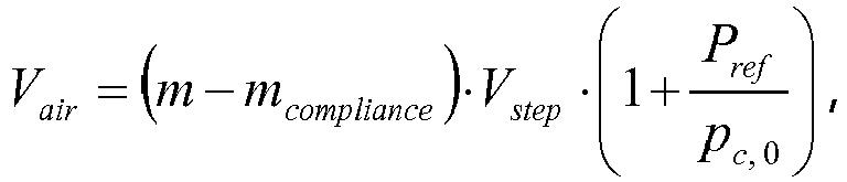
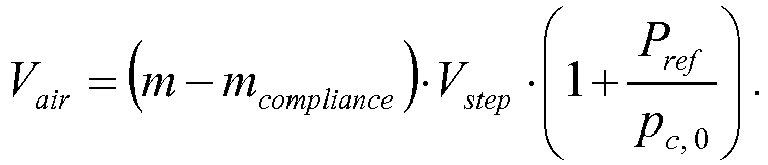
- In some embodiments including a second priming routine, the second priming routine includes taking into account a mechanical compliance of limiting walls of the dosing chamber for computing the air volume Vair. For this type of embodiment, the air volume Vair may be computed according to the formula:

- For embodiments where increasing or decreasing of the dosing chamber volume is achieved by displacing a dosing piston of the dosing unit in a dosing cylinder, and the dosing piston is displaceable in incremental steps, the before-given formula may be rewritten to
- In some embodiments, increasing of the dosing chamber volume is achieved by displacing a dosing piston of the dosing unit into a distal direction and decreasing of the dosing chamber volume is achieved by displacing the dosing piston into an opposite proximal direction. This is the case for dosing units that include a dosing cylinder with a bore-like axial recess and a dosing piston that is slidably and sealing received in the recess, as shown, e.g. in
Figure 1 . For this type of embodiment, the piston accordingly forms a movable limiting wall of the dosing chamber, while other limiting walls of the dosing chamber are formed by the dosing cylinder. For this type of embodiment, the dosing unit is designed as syringe-like positive displacement pump, with the dosing cylinder corresponding to the syringe body. - In some embodiments, opening and closing of the filling valve and the draining valve includes rotating a common shutoff body of the dosing unit. Corresponding dosing unit designs are disclosed in the European patent application
EP13195599.9 Figure 1 and theEP1970677A1 . - According to a further aspect, objects of the present invention are achieved by providing a control unit. The control unit is designed for controlling operation of a dosing unit of an ambulatory infusion system. The control unit includes a metering chamber volume controller, a valve controller, and a pressure sensor interface. The control unit The control unit is designed for controlling execution of a first priming routine. The first priming routine includes:
- providing the dosing unit with a dosing chamber of the dosing unit having a minimal dosing chamber volume, a draining valve of the dosing unit being closed and a filling valve of the dosing unit being open;
- measuring an initial reservoir fluid pressure p 2 and computing, based on the initial reservoir fluid pressure p 2, a first priming volume v 1, with the liquid drug reservoir being fluidic coupled with the dosing chamber via a reservoir coupling conduit and the opened filling valve ;
- increasing the dosing chamber volume by the first priming volume v 1, with the first priming volume v 1 being computed such that the reservoir coupling conduit is filled with liquid drug substantially completely at the end of the dosing chamber volume increasing;
- closing the filling valve and opening the draining valve ;
- emptying the dosing unit by decreasing the dosing chamber volume to the minimal dosing chamber volume.
- The control unit is realized by electronic circuitry, based on programmable components such as one or more micro controllers or microcomputer, and associated peripheral circuitry, such as power supply circuitry, safety circuitry and actuator driver circuitry. The control flow may be hard-coded or, fully or partly, be realized by a computer program product including a non-transient computer readable medium having stored therein computer program code. The non-transient computer readable medium may especially be realized as Read-Only-Memory (ROM) or non-volatile Random Access Memory (RAM).
- In some embodiments of the control unit, the control unit is further designed for controlling, prior to controlling execution of the first priming routine, execution of a sensor calibration routine by:
- controlling, via the valve controller, the valve actuator to close the filling valve and the draining valve, resulting in the dosing chamber being fluidic isolated;
- controlling, via the dosing chamber volume controller, the dosing chamber actuator to decrease the dosing chamber volume, thereby compressing the gas inside the dosing unit to a pre-set compression factor c;
- reading, via the pressure sensor interface, at the compression factor c an output value


- controlling, via the valve controller, the valve actuator to open the draining valve with the filling valve staying closed;
- controlling, via the dosing chamber volume controller, the dosing chamber actuator to further decrease the dosing chamber volume, thereby expelling the gas out of the dosing chamber.
- In some embodiments of the control unit, the control unit is further designed for controlling, following to controlling execution of the first priming routine, controlling execution of a second priming routine. The second priming routine includes:
- closing the draining valve and to open the filling valve;
- increasing the dosing chamber volume by a second priming volume v 2 ;
- closing the filling valve with the draining valve staying closed, resulting in the dosing chamber to be fluidic isolated;
- varying the dosing chamber volume and monitoring, during the variation, a chamber pressure pC inside the dosing chamber, and stopping the variation upon the chamber pressure pC equalling a reference pressure pref ;
- computing, based on an amount of variation of the dosing chamber volume, an air volume vair of air inside the dosing chamber.
- In some embodiments of the control unit, the dosing chamber volume controller is configured for controlling the dosing chamber actuator to alternatively increase or decrease the dosing chamber volume continuously or in incremental steps.
- In some embodiments of the control unit, the valve controller is designed for controlling a rotary valve motor as valve actuator and the dosing chamber volume controller is designed for controlling a rotary dosing chamber motor as dosing chamber actuator.
- The control unit may further be designed for controlling the execution of a method for initializing a dosing unit in accordance according to any embodiment for such a method as generally described before as well as further below in the context of exemplary embodiments. Therefore, any disclosed embodiment of such a method likewise discloses a corresponding embodiment of a control unit that is designed for controlling execution of the disclosed method.
- According to a still further aspects, objects of the present invention are achieved by providing an ambulatory infusion device. The ambulatory infusion device includes a control unit according as generally described before and further below in the context of exemplary embodiments. The ambulatory infusion device further includes a valve actuator, the valve actuator being operatively coupled to the valve controller and being designed for engaging a valve actuator coupler of a dosing unit. The ambulatory infusion device further includes a dosing chamber actuator, the dosing chamber actuator being operatively coupled to the dosing chamber actuator controller and being designed for engaging a movable limiting wall of the dosing chamber. The ambulatory infusion device further includes a casing, the casing enclosing the control unit, the valve actuator and the dosing chamber actuator. The ambulatory infusion device further includes a dosing unit interface, the dosing unit interface being designed for releasably coupling the ambulatory infusion device with the dosing unit such that the valve actuator releasably engages a valve actuator coupler of a dosing unit.
-
- Figure 1
- (discussed above) schematically shows an exemplary dosing unit which may be used in the context of the present disclosure.
- Figure 2:
- shows an ambulatory infusion system that includes an exemplary ambulatory infusion device in accordance with the present disclosure, in a schematically view.
- Figure 3:
- shows the operational flow of a sequence, the sequence including a pressure calibration routine, a first priming routine, a second priming routine, and a finalization routine.
- Figure 4:
- shows the operational flow of a sensor calibration routine.
- Figure 5:
- shows the operational flow of a first priming routine.
- Figure 6:
- shows the operational flow of a second priming routine.
- Figure 7:
- shows the operational flow of a finalization routine.
- In the following, exemplary embodiments in accordance with the present invention are described in more detail with additional reference to the figures.
-
Figure 1 shows a dosing unit which is - as such - known from the prior art as exemplary embodiment of a dosing unit that may be used in the context of the present disclosure. Reference is made to the corresponding section of the Summary of Disclosure for a more detailed description and discussion of such a dosing unit. -
Figure 2 shows an exemplary ambulatory infusion system together with associated components in a schematic structural view together with associated components. The exemplary ambulatory infusion system includes adrug reservoir unit 10, adosing unit 20 and anambulatory infusion device 30. - The
drug reservoir 10 is exemplarily shown ascylindrical cartridge body 100 which receives adisplaceable piston 101 in a sealing and sliding way. Thepiston 101 is biased by anoptional biasing spring 102 in the direction A'. Alternatively, theliquid drug reservoir 100 may be realized in a different way, e.g. as flexible bag or pouch or as semi-flexible drug reservoir with a rigid body and a flexible cover which allows the liquid-filled volume to vary. - The
dosing unit 20 includes adosing cylinder 200 with a bore-like recess which receives adisplaceable dosing piston 201 in a sealing and sliding way, thus forming a syringe-like arrangement with adosing chamber 202 of variable volume. The volume of thedosing chamber 202 may be increased by displacing thedosing piston 201 in a distal direction and may be decreased by displacing thedosing piston 201 in a proximal direction A. Thedosing cylinder 200 and thepiston 201 accordingly form, in combination, a miniaturized dosing piston pump. Via a common fluidic port (not referenced) at the proximal end of thedosing cylinder 200, thedosing cylinder 200 and in particular thedosing chamber 202 is fluidic coupled with a fillingvalve valve closed state liquid drug reservoir 10. The draining valve is further fluidic coupled to aninfusion line 500. - The
dosing unit 20 further includes apressure sensor 203 that is realized as relative pressure sensor for pressure measurement relative to an environmental reference pressure. The pressure sensor may be realized in a number of ways, e.g. as piezo-resistive or capacitive sensor or as optical pressure sensor. Thepressure sensor 203 is fluidic coupled to the fluidic port of thedosing cylinder 200. If the filling valve is open, 204b, and the draining valve is closed, 205a, a fluidic coupling is present between theliquid drug reservoir 10 and thepressure sensor 203 and thedosing chamber 202, such that the pressure that is measured by thepressure sensor 203 corresponds, in a static or equilibrium state, to the reservoir pressure. If the draining valve is open, 205b, and the filling valve is closed, 204a, a fluidic coupling is present between the infusion line 50 and thepressure sensor 203 as well as thedosing chamber 202, such that the pressure that is measured by thepressure sensor 203 corresponds, in a static or equilibrium state, to infusion line pressure. both of filling valve and the draining valve are closed, thedosing chamber 202 and thepressure sensor 203 are fluidic isolated from both of thedrug reservoir 10 and the infusion line 50. - The
ambulatory infusion device 30 includes acontrol unit 300, adosing chamber drive valve drive - The
dosing chamber drive dosing chamber motor 310, e.g. a stepper motor, a standard DC motor, or a brushless DC motor. In an operable state, output element, e.g. a rotary output shaft, of thedosing chamber motor 310 is coupled to thedosing piston 201. Between the motor output shaft and thedosing piston 201, adosing chamber gear 311 is arranged. The dosing chamber gear may be realized as combination of a helical reduction gear and a linear displaceable threaded spindle that acts on thedosing piston 201 via releasable engagement for displacing thedosing piston 201 in proximal or distal direction, respectively. - The
valve drive valve actuator 321 that may be realized in the same way as the dosing chamber actuator 31 0, and is in the following considered as rotary valve driver motor. An output shaft of thevalve driver motor 320 is, in an operational state, coupled to the fillingvalve valve valve driver gear 321 which may be realized as combination of a helical reduction gear and coupler for releasable rotational engagement with the fillingvalve valve - The
control unit 300 is typically realized as controller-based circuitry. Thecontrol unit 300 includes a dosingchamber volume controller 302 that is operatively coupled to and controls operation of thedosing chamber actuator 310. Similarly, thecontrol unit 300 includes avalve controller 304 that is operatively coupled to and controls operation of thevalve actuator 321. - The
control unit 300 further includes apressure sensor interface 303 that is, in an operational state, coupled to thepressure sensor 203. The kind of coupling depends on the design and operational principle of thepressure sensor 203. In case of thepressure sensor 203 being, e.g. a piezo-resistive or capacitive sensor, the coupling is typical electric. In case of thepressure sensor 203 being an optical sensor, the coupling may also be optical. Thepressure sensor interface 303 includes all circuitry that is required for coupling thepressure sensor 203 to acentral control unit 301 as discussed below. The pressure sensor interface may especially include components such as sensor power supply, amplifiers, filters, analogue-to-digital converters and/or further signal conditioning circuitry. - The
control unit 300 further includes acentral controller 301 that controls the overall operation of theambulatory infusion device 30 and is operatively coupled to the dosingchamber volume controller 302, thevalve controller 304, and the pressure sensor interface. The central controller controls the overall operation of theambulatory infusion device 300. Thecentral controller 301 is typically realized by a single or multitude of components such as micro controllers micro processors, ASICS, and peripheral components. - The different functional units of the
control 300 as shown inFigure 2 does not imply any specific hardware structure. Some or all functional units that are shown distinct from each other inFigure 2 may be realized, fully or partly, by common hardware components; similarly, a functional unit may be distributed over a number of hardware components. - A housing (not shown) may be present that houses the shown and further components of the
ambulatory infusion device 30 and may removable receive thedrug reservoir 10 and thedosing unit 20 in corresponding housing compartments, thus forming an operational ambulatory infusion system. Thedrug reservoir 10 and thedosing unit 20 may also be provided as combined module. Furthermore, either or both of thedrug reservoir 10 and thedosing unit 20 may be attached to a housing of theambulatory infusion device 30 rather than being received by a housing compartment. - The design of the
dosing unit 20, thedosing chamber drive valve drive 321, 322, may follow the disclosure of the European patent applicationEP13195599.9 EP13195599.9 dosing cylinder 200 relative to a stationary part as disclosed, e.g. in the before mentionedEP1970677A1 (see, e.g.Fig. 1 ) orEP2163273A1 . Furthermore, a single common actuator, such as a single rotary motor, may be used for both valve switching and piston displacement. - In the before-mentioned designs, the filling
valve valve valve valve control unit 300. - Furthermore, the
dosing unit 20 may include a pump different from a piston pump with thedosing cylinder 200 and the dosing piston 2011. -
Figure 3 shows the operational flow of a method for initializing a dosing unit in accordance with the present disclosure in a schematic view. The steps of the method, in combination, are referred to as step S1. Step S1 includes a sensor calibration routine with steps S10, a first priming routine with steps S11, a second priming routine with steps S12, and an additional finalization routine with steps S13 in sequential order. -
Figure 4 shows the operational flow of a sensor calibration routine S10, with the sensor calibration routine including steps S100, S101, S102, S102, S103, S104, S105 in sequential order. In the initial step S100, both the filling valve and the draining valve are closed. - The step S100 includes determining the state of the filling
valve 204 and the drainingvalve 205 and closing the fillingvalve 204 or the draining valve if not closed. It is assumed that thedosing cylinder 201 is filled with (sterile) air or an other inert gas. Alternatively, thestep 100 may include, prior to closing both the filling valve and the draining valve, increasing the volume of themetering chamber 202 , thus filling thedosing cylinder 200 with air in a configuration where the drainingvalve 205 is open. - In the following step S101, the dosing chamber volume is decreased to a preset compression factor c 1 by displacing the
piston 201 into the proximal direction, thereby decreasing the dosing chamber volume. A typical suited value for the compression factor c 1 is, e.g. c 1 = 2, corresponding to a reduction of the dosing chamber volume by half. For a piston-type dosing unit where the minimum chamber volume is zero, this corresponds to a piston displacement by half of its total displacement range between the maximum and minimum dosing chamber volume. - In the following step S102, the output value of the
pressure sensor 203 at the compression factor c 1 is read. - In the subsequent step S103, a pressure sensor calibration is computed and stored. In case of a substantially linear relationship between the pressure p and the corresponding output value p* of the
pressure sensor 203, it may be sufficient in step S103 to determine the slope m of a linear calibration function p=m·p*. In a variant, the sensor calibration routine S10 includes, prior to closing both the filling valve and the draining valve in step S100, reading and storing an offset output value p 0* of thepressure sensor 203 in a state where the drainingvalve 205b is open and thedosing chamber 202 is accordingly vented, via the drainingvalve 205b, to the environment. In such embodiment, a sensor calibration p=m·p*+p 0 may be computed in step S103, where p 0 is an offset pressure that is measured by thepressure sensor 203 at the environmental reference pressure. - In a further variant, a sequence comprising the step S101 of reducing the dosing chamber volume and the following step S102 of reading the output value p* of the pressure sensor is carried out repeatedly. For this type of embodiment, the dosing chamber volume is reduced in equal or non-equal compression steps by displacing the
piston 201 in a number of displacement steps, and the output value of the p* is read and stored in each step. For this type of embodiment, the step S103 includes determining a non-linear relationship p=f(p*) using generally known best-fit or regression algorithms. - The before described steps S101, S102, S103 are based on a calibration method where the gas inside the dosing chamber is compressed to one or more pre-set compression factor(s) and the sensor output value(s) is/are read for this/those compression factor(s). Alternatively, however, the step S101 may include reducing the dosing chamber volume and reading the pressure sensor output continuously until the pressure sensor output value assumes a pre-set output value p 1*. For this type of embodiment, the subsequent step S102 includes determining the corresponding pressure p 1 from the piston displacement in step S101.
- In the subsequent step S104, the draining
valve 205 is opened with the fillingvalve 204 staying closed. Thereby, the compressed gas is partly expelled out of the dosing chamber via the draining valve until the pressure inside the dosing chamber equals the environmental pressure. In the further subsequent step S105, the dosing chamber volume is further decreased to the minimal dosing chamber volume by displacing the piston in the proximal direction. Thereby, thedosing cylinder 101 is emptied and the remaining gas is expelled out of thedosing chamber 202. -
Figure 5 shows the operational flow of a first priming routine S11, with the first priming routine S11 including steps S110, S111, S112, S113, S114, S115. It is assumed that the dosing chamber volume is the minimal dosing chamber volume at the beginning of the first priming routine S11. - In the step S110, the filling
valve 204 is opened and the drainingvalve 205 is closed. The step S110 may include, prior to a valve actuation, determining the state of the fillingvalve 204 and the drainingvalve 205, respectively. The step S110 may further include carrying out a valve actuation only if the fillingvalve 204 is not opened and/or the drainingvalve 205 is not closed. - In the subsequent step S111, the reservoir fluid pressure p 2 is measured by reading and evaluating the output signal provided by the
pressure sensor 203. - In the subsequent step S1 12, a first priming volume v 1 is computed based on the previously measured reservoir fluid pressure p 2 according to the above-discussed formula

- In the subsequent step S113, the dosing chamber volume is increased by the first priming volume v 1, which is achieved by displacing the
piston 201 into the distal direction. At the end of the piston displacement in the step S113, the dosing chamber corresponds a mixture of air and gas in dependence of the reservoir fluid pressure p 2. The reservoir coupling conduit, however, is in any case filled with liquid drug. - In the subsequent step S114, the filling
valve 204 is closed and the drainingvalve 205 is opened instead. In the further subsequent step S115, the dosing chamber volume is decreased to the minimal dosing chamber volume by displacing the piston into the proximal direction. Thereby, the mixture of air and liquid drug is expelled via the draining valve and the dosing unit is empty at the end of the step S115. -
Figure 6 shows the operational flow of a second priming routine S12, with the second priming routine S12 including steps S120, S121, S122, S123, S124, S125a, S125b, S126a, S126b, S127, S128, and S129. It is assumed that the dosing chamber volume is the minimal dosing chamber volume at the beginning of the first priming routine S12. - In step S120, the filling
valve 204 is opened and the drainingvalve 205 is closed. The step S120 may include, prior to a valve actuation, determining the state of the fillingvalve 204 and the drainingvalve 205, respectively. The step S110 may further include carrying out a valve actuation only if the fillingvalve 204 is not opened and/or the drainingvalve 205 is not closed. - In the subsequent step S121, the dosing chamber volume is increased by a second priming volume v 2, which is achieved by displacing the
piston 102 into the distal direction. Increasing the dosing chamber volume by the second priming volume v 2 results in sucking a second priming amount ofliquid drug reservoir 10 into the dosing chamber. The second priming amount of liquid drug may be identical to the second priming volume v 2 if no air/gas is suck from the liquid drug reservoir; otherwise, the second priming amount of liquid drug is smaller than the second priming volume v 2 and a the dosing chamber is filled with a mixture of liquid drug and air/gas at the end of step S121. - In the subsequent step S1 22, the filling
valve 204 is closed with the drainingvalve 205 staying closed, resulting in the dosing chamber being fluidic isolated. - In the subsequent step S123, the chamber pressure pC is measured by reading and evaluating the output value of the
pressure sensor 203. In the subsequent step S1 24, the operational flow branches in dependence on whether the dosing chamber pressure pC is positive or negative, that is, whether there is an over- or under pressure relative to the reference pressure pref. The measured chamber pressure pC is stored as initial chamber pressure value p C,0. - If the dosing chamber pressure pC is positive, the dosing chamber volume is increased in the step S125a by displacing the
piston 201 by an incremental step in the distal direction, thereby decreasing the positive chamber pressure pC. In the subsequent step S126a, it is determined, by reading and evaluating the output value of thepressure sensor 203, if the dosing chamber pressure pC equals the reference pressure pref. If this is the case, the operational flow proceeds with step the S127. Otherwise, the operational flow proceeds with repeating the step S125a. - If the dosing chamber pressure pC is negative, the dosing chamber volume is decreased in the step S1 25b by displacing the
piston 201 by an incremental step in the proximal direction, thereby decreasing the absolute value of the negative chamber pressure pC. In the subsequent step S126b, it is determined, by reading and evaluating the output value of thepressure sensor 203, if the dosing chamber pressure equals the reference pressure pref. If this is the case, the operational flow proceeds with step the S127. Otherwise, the operational flow proceeds with repeating the step S1 25b. - When repeatedly carrying out the sequence of steps S125a, S126a, or S125a, S126b, respectively, the number of displacement steps m of the
piston 201 that is required for equalizing the dosing chamber pressure pC with the reference pressure pref is counted. - After equalling the dosing chamber pressure pC with the reference pressure pref in steps S125a and S126a, or S125b and S126b, respectively, the operational flow proceeds with the step S127. In the step S127, an amount of air vair inside the dosing chamber is computed based on the above-discussed formula:
- In the subsequent step S1 28, the air volume Vair as computed in the step S1 27, is compared with a pre-set threshold air volume V air, theshold. If the air volume Vair exceeds the threshold air volume V air,threshold , an alert is provided in the step S129.
-
Figure 7 shows the operational flow of a finalization routine S13, the finalization routine S13 following the second priming routine S12 and including the steps S130, S131, S132, S133, S134. - In the step S130, the dosing chamber volume is increased by displacing the
piston 201 by mS steps in the distal direction, thereby creating a negative pressure inside the dosing chamber. The number of steps mS is determined such that resulting piston displacement is somewhat larger than the mechanical backlash resulting from reversing the displacement direction of thepiston 201. - In the subsequent step S131, the dosing chamber volume is decreased by displacing the
piston 201 by an incremental step in the proximal direction. In the subsequent step S132, the chamber pressure pC is measured by reading and evaluating the output value of thepressure sensor 203. - In the subsequent step S133, it is determined if the dosing chamber pressure pC equals the reference pressure pref. If this is the case, the operational flow proceeds with step S134. Otherwise, the operational flow proceeds with step S131.
- In the subsequent step S134, the draining
valve 205 is opened with the fillingvalve 204 staying closed. In the subsequent step S135, the dosing chamber volume is decreased to the minimal chamber volume by displacing thepiston 102 in the proximal direction. Thereby, the liquid drug is expelled, via the drainingvalve 205 out of the dosing chamber and into the infusion line 50, thus priming theinfusion line 500. - The second priming routine and the finalization routine may not only be carried out in the context of initialization and priming, but may be carried out for (refilling) the dosing chamber during subsequent regular infusion operation. This is approach is particularly favourable since it involves a air volume computation and favourably providing an alarm in case of an excessive air volume every time the dosing chamber of the dosing unit is (re-)filled. Therefore, these routines also disclose a method for filling or refilling a dosing chamber of a dosing unit of the described type.
Claims (15)
- Method for initializing a dosing unit (20) of an ambulatory infusion system, the method including carrying out a first priming routine, the first priming routine including:- providing the dosing unit (20) with a dosing chamber (202) of the dosing unit (20) having a minimal dosing chamber volume, a draining valve (205) of the dosing unit (20) being closed and a filling valve (204) of the dosing unit (20) being open;- measuring an initial reservoir fluid pressure p 2 and computing, based on the initial reservoir fluid pressure p 2, a first priming volume v 1, with a liquid drug reservoir (10) being fluidic coupled with the dosing chamber (202) via a reservoir coupling conduit and the opened filling valve (204);- increasing the dosing chamber volume by the first priming volume v 1, with the first priming volume v 1 being computed such that the reservoir coupling conduit is filled with liquid drug substantially completely at the end of the dosing chamber volume increasing;- closing the filling valve (204) and opening the draining valve (205);- emptying the dosing unit (20) by decreasing the dosing chamber volume to the minimal dosing chamber volume.
- Method according to claim 1, wherein the method further includes, prior to carrying out the first priming routine, carrying out a sensor calibration routine, the sensor calibration routine including:- providing the dosing unit (20) in an initial state with the dosing chamber (202) being gas-filled and both of the filling valve (204) and the draining valve (205) being closed, resulting in the dosing chamber (202) being fluidic isolated.- decreasing the dosing chamber volume, thereby compressing the gas inside the dosing unit (20) to a compression factor c 1;- reading, at the compression factor c 1, an output value

 - opening the draining valve (205) with the filling valve (204) staying closed;- emptying the dosing unit (20) by further decreasing the dosing chamber volume to the minimal dosing chamber volume.
 - Method according to either of claim 1 or claim 2, wherein the method further includes, following carrying out the first priming routine, carrying out a second priming routine, the second priming routine including:- closing the draining valve (205) and opening the filling valve (204);- increasing the dosing chamber volume by a second priming volume;- closing the filling valve (204) with the draining valve (205) staying closed, resulting in the dosing chamber (202) being fluidic isolated;- varying the dosing chamber volume and monitoring, during the variation, a dosing chamber pressure pC, and stopping the variation upon the dosing chamber pressure pC equalling a reference pressure;- computing, based on an amount of variation of the dosing chamber volume, an air volume vair of air inside the dosing chamber (202).
- Method according to claim 3, wherein the second priming routine includes: the comparing the air volume Vair with a pre-set threshold air volume V air,threshold and providing an alert if the air volume vair exceeds the pre-set threshold air volume V air,threshold .
- Method according to either of claim 3 or claim 4, wherein the second priming routine includes: taking into account a mechanical compliance of limiting walls of the dosing chamber (202) for computing the air volume Vair .
- Method according to either of claim 1 to claim 5, wherein the minimal dosing chamber volume is negligible or zero.
- Method according to either of claim 1 to claim 6, wherein the first priming routine includes: computing the first priming volume v 1 as

- Method according to either of claim 1 to claim 7, wherein increasing of the dosing chamber volume is achieved by displacing a piston (201) of the dosing unit (20) into a distal direction, and wherein decreasing of the dosing chamber volume is achieved by displacing the piston (201) into an opposite proximal direction, with the piston (201) being received in a dosing cylinder (200) of the dosing unit (20) and the dosing cylinder (200) extending along a piston displacement axis, thus forming a movable limiting wall of the dosing chamber (202).
- Method according to either of claim 1 to claim 8, wherein opening and closing of the filling valve (204) and the draining valve between an open and a closed state includes rotating a common shutoff body of the dosing unit (20).
- Control unit (30), the control unit being designed for controlling operation of a dosing unit (20) of an ambulatory infusion system, the control unit (30) including a dosing chamber volume controller (302), a valve controller (304) and a pressure sensor interface (303), the control unit (30) being further designed for controlling execution of an initialization routine, the initialization routine including a first priming routine, the first priming routine including:- providing the dosing unit (20) with a dosing chamber (202) of the dosing unit (20) having a minimal dosing chamber volume, a draining valve (205) of the dosing unit (20) being closed and a filling valve (204) of the dosing unit (20) being open;- measuring an initial reservoir fluid pressure p 2 and computing, based on the initial reservoir fluid pressure p 2, a first priming volume v 1, with the liquid drug reservoir (10) being fluidic coupled with the dosing chamber (202) via a reservoir coupling conduit and the opened filling valve (204);- increasing the dosing chamber volume by the first priming volume v 1, with the first priming volume v 1 being computed such that the reservoir coupling conduit is filled with liquid drug substantially completely at the end of the dosing chamber volume increasing;- closing the filling valve (204) and opening the draining valve (205);- emptying the dosing unit (20) by decreasing the dosing chamber volume to the minimal dosing chamber volume.
- Control unit (300) according to claim 10, the control unit (300) being further designed for controlling, prior to controlling execution of the first priming routine, execution of a sensor calibration routine, the sensor calibration routine including:- closing the filling valve (204) and the draining valve (205), resulting in the dosing chamber (202) being fluidic isolated;- decreasing the dosing chamber volume, thereby compressing gas inside the dosing unit (20) to a compression factor c 1;- reading, at the compression factor c 1, an output value

 - opening the draining valve (205) with the filling valve (204) staying closed;- emptying the dosing unit (20) by further decreasing the dosing chamber volume to the minimal dosing chamber volume.
 - Control unit (300) according to either of claim 10 or claim 11, the control unit (300) being further designed for controlling, following to controlling execution of the first priming routine, controlling execution of a second priming, the second priming routine including:- closing the draining valve (205) and to open the filling valve (204);- increasing the dosing chamber volume by a second priming volume v 2 ;- closing the filling valve (204) with the draining valve (205) staying closed, resulting in the dosing chamber (202) to be fluidic isolated;- varying the dosing chamber volume and monitoring, during the variation, a chamber pressure pC inside the dosing chamber (202), and stopping the variation upon the chamber pressure pC equalling a reference pressure pref ;- computing, based on an amount of variation of the dosing chamber volume, an air volume vair of air inside the dosing chamber (202).
- Control unit (300) according to either of claim 10 to claim 12, wherein the dosing chamber volume controller (302) is designed for controlling a dosing chamber actuator (310) to alternatively increase or decrease the dosing chamber volume continuously or in incremental steps.
- Control unit (300) according to either of claim 10 to claim 13, wherein the valve controller (304) is designed for controlling a rotary valve motor as valve actuator (320) and the dosing chamber volume controller (302) is designed for controlling a rotary dosing chamber motor as dosing chamber actuator (310).
- Ambulatory infusion device (30), including:- a control unit (30) according to either of claim 10 to claim 14;- a valve actuator (32), the valve actuator (320) being operatively coupled to the valve controller (304) and being designed for engaging a valve actuator coupler of a dosing unit (20);- a dosing chamber actuator (310), the dosing chamber actuator (310) being operatively coupled to the dosing chamber actuator controller (302) and being designed for engaging a movable limiting wall (201) of the dosing chamber (202);- a casing, the casing enclosing the control unit (300), the valve actuator (320) and the dosing chamber actuator (310);- a dosing unit interface, the dosing unit interface being designed for releasably coupling the ambulatory infusion device (30) with the dosing unit (20) such that the valve actuator (304) releasably engages a valve actuator coupler of a dosing unit (20).
Priority Applications (7)
| Application Number | Priority Date | Filing Date | Title |
|---|---|---|---|
| EP14160177.3A EP2921189B1 (en) | 2014-03-17 | 2014-03-17 | Initalization of a dosing unit for drug infusion |
| DK14160177.3T DK2921189T3 (en) | 2014-03-17 | 2014-03-17 | Initialization of a drug infusion dosing unit |
| RU2016140516A RU2016140516A (en) | 2014-03-17 | 2015-02-18 | INITIALIZATION OF THE DOSING DEVICE FOR INFUSION OF MEDICINES |
| KR1020167025598A KR20160132855A (en) | 2014-03-17 | 2015-02-18 | Initialization of a dosing unit for drug infusion |
| US15/126,628 US10159784B2 (en) | 2014-03-17 | 2015-02-18 | Initialization of a dosing unit for drug infusion |
| PCT/EP2015/053405 WO2015139905A1 (en) | 2014-03-17 | 2015-02-18 | Initialization of a dosing unit for drug infusion |
| JP2016558099A JP2017507761A (en) | 2014-03-17 | 2015-02-18 | Initializing the dosing unit for drug injection |
Applications Claiming Priority (1)
| Application Number | Priority Date | Filing Date | Title |
|---|---|---|---|
| EP14160177.3A EP2921189B1 (en) | 2014-03-17 | 2014-03-17 | Initalization of a dosing unit for drug infusion |
Publications (2)
| Publication Number | Publication Date |
|---|---|
| EP2921189A1 EP2921189A1 (en) | 2015-09-23 |
| EP2921189B1 true EP2921189B1 (en) | 2017-08-02 |
Family
ID=50277126
Family Applications (1)
| Application Number | Title | Priority Date | Filing Date |
|---|---|---|---|
| EP14160177.3A Active EP2921189B1 (en) | 2014-03-17 | 2014-03-17 | Initalization of a dosing unit for drug infusion |
Country Status (7)
| Country | Link |
|---|---|
| US (1) | US10159784B2 (en) |
| EP (1) | EP2921189B1 (en) |
| JP (1) | JP2017507761A (en) |
| KR (1) | KR20160132855A (en) |
| DK (1) | DK2921189T3 (en) |
| RU (1) | RU2016140516A (en) |
| WO (1) | WO2015139905A1 (en) |
Families Citing this family (7)
| Publication number | Priority date | Publication date | Assignee | Title |
|---|---|---|---|---|
| ES2804530T3 (en) | 2016-12-14 | 2021-02-08 | Hoffmann La Roche | Ambulatory infusion device |
| EP3502469A1 (en) | 2017-12-20 | 2019-06-26 | Sensile Medical AG | Micropump |
| EP3505757A1 (en) | 2017-12-28 | 2019-07-03 | Sensile Medical AG | Micropump |
| US11806216B2 (en) * | 2018-07-16 | 2023-11-07 | Kci Licensing, Inc. | Fluid instillation apparatus for use with negative-pressure system incorporating wireless therapy monitoring |
| EP4401809A1 (en) * | 2021-09-15 | 2024-07-24 | Certus Critical Care, Inc. | Devices, systems, and methods for fluid delivery |
| US11718427B1 (en) * | 2022-05-01 | 2023-08-08 | Vital Manufacturing Inc. | Volumetric isobaric filling system |
| CN119097790A (en) * | 2023-06-08 | 2024-12-10 | 深圳硅基传感科技有限公司 | Device for delivering fluid based on microfluidic pump |
Family Cites Families (20)
| Publication number | Priority date | Publication date | Assignee | Title |
|---|---|---|---|---|
| US4778451A (en) * | 1986-03-04 | 1988-10-18 | Kamen Dean L | Flow control system using boyle's law |
| US5813842A (en) * | 1989-09-22 | 1998-09-29 | Tamari; Yehuda | Pressure sensitive valves for extracorporeal pumping-3 |
| US6190354B1 (en) * | 1994-09-16 | 2001-02-20 | Scimed Life Systems, Inc. | Balloon catheter with improved pressure source |
| EP1319417A1 (en) * | 2001-12-17 | 2003-06-18 | B. Braun Medizintechnologie GmbH | Method and apparatus for monitoring a fluid conduit system of a medical instrument |
| US6729327B2 (en) * | 2001-12-17 | 2004-05-04 | Joseph L. McFarland, Jr. | Portable, handheld, pneumatic driven medicinal nebulizer |
| US10537671B2 (en) * | 2006-04-14 | 2020-01-21 | Deka Products Limited Partnership | Automated control mechanisms in a hemodialysis apparatus |
| US8409441B2 (en) * | 2007-02-27 | 2013-04-02 | Deka Products Limited Partnership | Blood treatment systems and methods |
| ATE445145T1 (en) | 2007-03-15 | 2009-10-15 | Hoffmann La Roche | INFUSION SYSTEM WITH A DOSING DEVICE |
| US9044537B2 (en) * | 2007-03-30 | 2015-06-02 | Medtronic, Inc. | Devices and methods for detecting catheter complications |
| US20080237142A1 (en) * | 2007-04-02 | 2008-10-02 | Battelle Energy Alliance, Llc | Systems and methods for concentrating substances in fluid samples |
| US9285354B2 (en) * | 2007-04-02 | 2016-03-15 | The United States Of America As Represented By The Administrator Of The U.S. Environmental Protection Agency | Systems and methods for the detection of low-level harmful substances in a large volume of fluid |
| US7892197B2 (en) * | 2007-09-19 | 2011-02-22 | Fresenius Medical Care Holdings, Inc. | Automatic prime of an extracorporeal blood circuit |
| US9057370B2 (en) * | 2008-08-08 | 2015-06-16 | Hamilton Company | Negative dead volume syringe |
| DK2163273T3 (en) | 2008-09-12 | 2013-07-29 | Hoffmann La Roche | Dosage unit and outpatient infusion unit with dosage unit |
| US8733736B2 (en) * | 2009-05-27 | 2014-05-27 | Carefusion 303, Inc. | Intravenous piston pump disposable and mechanism |
| WO2012126745A2 (en) * | 2011-03-18 | 2012-09-27 | Gambro Lundia Ab | Methods and devices for operating an infusion system |
| EP3498316B1 (en) * | 2011-11-04 | 2020-07-22 | DEKA Products Limited Partnership | Medical treatment system and methods using a plurality of fluid lines |
| ES2641380T3 (en) * | 2012-12-14 | 2017-11-08 | Gambro Lundia Ab | Repositioning diaphragm for pressure capsule using position detection |
| DK2881128T3 (en) | 2013-12-04 | 2019-01-28 | Hoffmann La Roche | Ambulatory infusion system comprising a step switch mechanism for valve control |
| AU2016249994B2 (en) * | 2015-04-15 | 2020-04-02 | Gambro Lundia Ab | Treatment system with infusion apparatus pressure priming |
-
2014
- 2014-03-17 EP EP14160177.3A patent/EP2921189B1/en active Active
- 2014-03-17 DK DK14160177.3T patent/DK2921189T3/en active
-
2015
- 2015-02-18 KR KR1020167025598A patent/KR20160132855A/en not_active Ceased
- 2015-02-18 RU RU2016140516A patent/RU2016140516A/en not_active Application Discontinuation
- 2015-02-18 US US15/126,628 patent/US10159784B2/en active Active
- 2015-02-18 WO PCT/EP2015/053405 patent/WO2015139905A1/en not_active Ceased
- 2015-02-18 JP JP2016558099A patent/JP2017507761A/en active Pending
Also Published As
| Publication number | Publication date |
|---|---|
| RU2016140516A (en) | 2018-04-18 |
| WO2015139905A1 (en) | 2015-09-24 |
| EP2921189A1 (en) | 2015-09-23 |
| JP2017507761A (en) | 2017-03-23 |
| US10159784B2 (en) | 2018-12-25 |
| DK2921189T3 (en) | 2017-11-13 |
| KR20160132855A (en) | 2016-11-21 |
| US20170106140A1 (en) | 2017-04-20 |
Similar Documents
| Publication | Publication Date | Title |
|---|---|---|
| EP2921189B1 (en) | Initalization of a dosing unit for drug infusion | |
| US9962486B2 (en) | System and method for detecting occlusions in an infusion pump | |
| JP6591806B2 (en) | Internal cam metering pump | |
| AU2010217760B2 (en) | Methods and devices for determination of flow reservoir volume | |
| US9250106B2 (en) | Methods and devices for determination of flow reservoir volume | |
| US9402951B2 (en) | Infusion pump device and method for improved dosing | |
| EP2698178B1 (en) | Pump engine with metering system for dispensing liquid medication | |
| EP2696914B1 (en) | Infusion pump device with improved priming of the fluidic system and method for priming such an infusion pump device | |
| CN103458940B (en) | There is the infusion pump devices of cylinder-piston administration unit and the detection of optics piston position | |
| DK3012600T3 (en) | Dosage device for an infusion system | |
| BR102020005161A2 (en) | PROCEDURE FOR CALIBRATING A PERISTALTIC PUMP, PROCEDURE FOR DISPENSING A QUANTITY OF LIQUID THROUGH PERISTALTIC PUMP AND DEVICE FOR THE PREPARATION OF STERILE PREPARATIONS THAT CAN PERFORM THE SAME | |
| JP7703602B2 (en) | Drug Delivery Devices | |
| JP7387441B2 (en) | Pump systems, dialysis machines, and methods of operating pump systems | |
| CN101495165A (en) | Device for administration of fluid product | |
| EP2062605A1 (en) | Calibrating device for dosing machines of radioactive substances | |
| CN219307570U (en) | Drug delivery system and drug delivery device | |
| US20130158501A1 (en) | Device for the dosed dispensing of a fluidic medium | |
| US12440617B2 (en) | Linear activated drug dosing pump system | |
| HK1192179B (en) | Infusion pump device with cylinder-piston dosing unit and optical piston position detection | |
| KR20090018913A (en) | Dosage device for fluid products |
Legal Events
| Date | Code | Title | Description |
|---|---|---|---|
| PUAI | Public reference made under article 153(3) epc to a published international application that has entered the european phase |
Free format text: ORIGINAL CODE: 0009012 |
|
| AK | Designated contracting states |
Kind code of ref document: A1 Designated state(s): AL AT BE BG CH CY CZ DE DK EE ES FI FR GB GR HR HU IE IS IT LI LT LU LV MC MK MT NL NO PL PT RO RS SE SI SK SM TR |
|
| AX | Request for extension of the european patent |
Extension state: BA ME |
|
| 17P | Request for examination filed |
Effective date: 20160323 |
|
| RBV | Designated contracting states (corrected) |
Designated state(s): AL AT BE BG CH CY CZ DE DK EE ES FI FR GB GR HR HU IE IS IT LI LT LU LV MC MK MT NL NO PL PT RO RS SE SI SK SM TR |
|
| RAP1 | Party data changed (applicant data changed or rights of an application transferred) |
Owner name: ROCHE DIABETES CARE GMBH Owner name: F. HOFFMANN-LA ROCHE AG |
|
| GRAP | Despatch of communication of intention to grant a patent |
Free format text: ORIGINAL CODE: EPIDOSNIGR1 |
|
| STAA | Information on the status of an ep patent application or granted ep patent |
Free format text: STATUS: GRANT OF PATENT IS INTENDED |
|
| INTG | Intention to grant announced |
Effective date: 20170227 |
|
| GRAS | Grant fee paid |
Free format text: ORIGINAL CODE: EPIDOSNIGR3 |
|
| GRAA | (expected) grant |
Free format text: ORIGINAL CODE: 0009210 |
|
| STAA | Information on the status of an ep patent application or granted ep patent |
Free format text: STATUS: THE PATENT HAS BEEN GRANTED |
|
| AK | Designated contracting states |
Kind code of ref document: B1 Designated state(s): AL AT BE BG CH CY CZ DE DK EE ES FI FR GB GR HR HU IE IS IT LI LT LU LV MC MK MT NL NO PL PT RO RS SE SI SK SM TR |
|
| REG | Reference to a national code |
Ref country code: CH Ref legal event code: EP Ref country code: AT Ref legal event code: REF Ref document number: 913778 Country of ref document: AT Kind code of ref document: T Effective date: 20170815 |
|
| REG | Reference to a national code |
Ref country code: IE Ref legal event code: FG4D |
|
| REG | Reference to a national code |
Ref country code: DE Ref legal event code: R096 Ref document number: 602014012411 Country of ref document: DE |
|
| REG | Reference to a national code |
Ref country code: DK Ref legal event code: T3 Effective date: 20171108 |
|
| REG | Reference to a national code |
Ref country code: NL Ref legal event code: FP |
|
| REG | Reference to a national code |
Ref country code: AT Ref legal event code: MK05 Ref document number: 913778 Country of ref document: AT Kind code of ref document: T Effective date: 20170802 |
|
| REG | Reference to a national code |
Ref country code: LT Ref legal event code: MG4D |
|
| PG25 | Lapsed in a contracting state [announced via postgrant information from national office to epo] |
Ref country code: HR Free format text: LAPSE BECAUSE OF FAILURE TO SUBMIT A TRANSLATION OF THE DESCRIPTION OR TO PAY THE FEE WITHIN THE PRESCRIBED TIME-LIMIT Effective date: 20170802 Ref country code: SE Free format text: LAPSE BECAUSE OF FAILURE TO SUBMIT A TRANSLATION OF THE DESCRIPTION OR TO PAY THE FEE WITHIN THE PRESCRIBED TIME-LIMIT Effective date: 20170802 Ref country code: NO Free format text: LAPSE BECAUSE OF FAILURE TO SUBMIT A TRANSLATION OF THE DESCRIPTION OR TO PAY THE FEE WITHIN THE PRESCRIBED TIME-LIMIT Effective date: 20171102 Ref country code: LT Free format text: LAPSE BECAUSE OF FAILURE TO SUBMIT A TRANSLATION OF THE DESCRIPTION OR TO PAY THE FEE WITHIN THE PRESCRIBED TIME-LIMIT Effective date: 20170802 Ref country code: FI Free format text: LAPSE BECAUSE OF FAILURE TO SUBMIT A TRANSLATION OF THE DESCRIPTION OR TO PAY THE FEE WITHIN THE PRESCRIBED TIME-LIMIT Effective date: 20170802 Ref country code: AT Free format text: LAPSE BECAUSE OF FAILURE TO SUBMIT A TRANSLATION OF THE DESCRIPTION OR TO PAY THE FEE WITHIN THE PRESCRIBED TIME-LIMIT Effective date: 20170802 |
|
| REG | Reference to a national code |
Ref country code: FR Ref legal event code: PLFP Year of fee payment: 5 |
|
| PG25 | Lapsed in a contracting state [announced via postgrant information from national office to epo] |
Ref country code: LV Free format text: LAPSE BECAUSE OF FAILURE TO SUBMIT A TRANSLATION OF THE DESCRIPTION OR TO PAY THE FEE WITHIN THE PRESCRIBED TIME-LIMIT Effective date: 20170802 Ref country code: IS Free format text: LAPSE BECAUSE OF FAILURE TO SUBMIT A TRANSLATION OF THE DESCRIPTION OR TO PAY THE FEE WITHIN THE PRESCRIBED TIME-LIMIT Effective date: 20171202 Ref country code: BG Free format text: LAPSE BECAUSE OF FAILURE TO SUBMIT A TRANSLATION OF THE DESCRIPTION OR TO PAY THE FEE WITHIN THE PRESCRIBED TIME-LIMIT Effective date: 20171102 Ref country code: ES Free format text: LAPSE BECAUSE OF FAILURE TO SUBMIT A TRANSLATION OF THE DESCRIPTION OR TO PAY THE FEE WITHIN THE PRESCRIBED TIME-LIMIT Effective date: 20170802 Ref country code: GR Free format text: LAPSE BECAUSE OF FAILURE TO SUBMIT A TRANSLATION OF THE DESCRIPTION OR TO PAY THE FEE WITHIN THE PRESCRIBED TIME-LIMIT Effective date: 20171103 Ref country code: RS Free format text: LAPSE BECAUSE OF FAILURE TO SUBMIT A TRANSLATION OF THE DESCRIPTION OR TO PAY THE FEE WITHIN THE PRESCRIBED TIME-LIMIT Effective date: 20170802 Ref country code: PL Free format text: LAPSE BECAUSE OF FAILURE TO SUBMIT A TRANSLATION OF THE DESCRIPTION OR TO PAY THE FEE WITHIN THE PRESCRIBED TIME-LIMIT Effective date: 20170802 |
|
| PG25 | Lapsed in a contracting state [announced via postgrant information from national office to epo] |
Ref country code: CZ Free format text: LAPSE BECAUSE OF FAILURE TO SUBMIT A TRANSLATION OF THE DESCRIPTION OR TO PAY THE FEE WITHIN THE PRESCRIBED TIME-LIMIT Effective date: 20170802 Ref country code: RO Free format text: LAPSE BECAUSE OF FAILURE TO SUBMIT A TRANSLATION OF THE DESCRIPTION OR TO PAY THE FEE WITHIN THE PRESCRIBED TIME-LIMIT Effective date: 20170802 |
|
| REG | Reference to a national code |
Ref country code: DE Ref legal event code: R097 Ref document number: 602014012411 Country of ref document: DE |
|
| PG25 | Lapsed in a contracting state [announced via postgrant information from national office to epo] |
Ref country code: EE Free format text: LAPSE BECAUSE OF FAILURE TO SUBMIT A TRANSLATION OF THE DESCRIPTION OR TO PAY THE FEE WITHIN THE PRESCRIBED TIME-LIMIT Effective date: 20170802 Ref country code: SK Free format text: LAPSE BECAUSE OF FAILURE TO SUBMIT A TRANSLATION OF THE DESCRIPTION OR TO PAY THE FEE WITHIN THE PRESCRIBED TIME-LIMIT Effective date: 20170802 Ref country code: IT Free format text: LAPSE BECAUSE OF FAILURE TO SUBMIT A TRANSLATION OF THE DESCRIPTION OR TO PAY THE FEE WITHIN THE PRESCRIBED TIME-LIMIT Effective date: 20170802 Ref country code: SM Free format text: LAPSE BECAUSE OF FAILURE TO SUBMIT A TRANSLATION OF THE DESCRIPTION OR TO PAY THE FEE WITHIN THE PRESCRIBED TIME-LIMIT Effective date: 20170802 |
|
| PLBE | No opposition filed within time limit |
Free format text: ORIGINAL CODE: 0009261 |
|
| STAA | Information on the status of an ep patent application or granted ep patent |
Free format text: STATUS: NO OPPOSITION FILED WITHIN TIME LIMIT |
|
| 26N | No opposition filed |
Effective date: 20180503 |
|
| PG25 | Lapsed in a contracting state [announced via postgrant information from national office to epo] |
Ref country code: SI Free format text: LAPSE BECAUSE OF FAILURE TO SUBMIT A TRANSLATION OF THE DESCRIPTION OR TO PAY THE FEE WITHIN THE PRESCRIBED TIME-LIMIT Effective date: 20170802 |
|
| GBPC | Gb: european patent ceased through non-payment of renewal fee |
Effective date: 20180317 |
|
| PG25 | Lapsed in a contracting state [announced via postgrant information from national office to epo] |
Ref country code: MC Free format text: LAPSE BECAUSE OF FAILURE TO SUBMIT A TRANSLATION OF THE DESCRIPTION OR TO PAY THE FEE WITHIN THE PRESCRIBED TIME-LIMIT Effective date: 20170802 |
|
| REG | Reference to a national code |
Ref country code: BE Ref legal event code: MM Effective date: 20180331 |
|
| REG | Reference to a national code |
Ref country code: IE Ref legal event code: MM4A |
|
| PG25 | Lapsed in a contracting state [announced via postgrant information from national office to epo] |
Ref country code: LU Free format text: LAPSE BECAUSE OF NON-PAYMENT OF DUE FEES Effective date: 20180317 |
|
| PG25 | Lapsed in a contracting state [announced via postgrant information from national office to epo] |
Ref country code: IE Free format text: LAPSE BECAUSE OF NON-PAYMENT OF DUE FEES Effective date: 20180317 |
|
| PG25 | Lapsed in a contracting state [announced via postgrant information from national office to epo] |
Ref country code: GB Free format text: LAPSE BECAUSE OF NON-PAYMENT OF DUE FEES Effective date: 20180317 Ref country code: BE Free format text: LAPSE BECAUSE OF NON-PAYMENT OF DUE FEES Effective date: 20180331 |
|
| PG25 | Lapsed in a contracting state [announced via postgrant information from national office to epo] |
Ref country code: MT Free format text: LAPSE BECAUSE OF NON-PAYMENT OF DUE FEES Effective date: 20180317 |
|
| PG25 | Lapsed in a contracting state [announced via postgrant information from national office to epo] |
Ref country code: TR Free format text: LAPSE BECAUSE OF FAILURE TO SUBMIT A TRANSLATION OF THE DESCRIPTION OR TO PAY THE FEE WITHIN THE PRESCRIBED TIME-LIMIT Effective date: 20170802 |
|
| PGFP | Annual fee paid to national office [announced via postgrant information from national office to epo] |
Ref country code: DK Payment date: 20200226 Year of fee payment: 7 |
|
| PG25 | Lapsed in a contracting state [announced via postgrant information from national office to epo] |
Ref country code: PT Free format text: LAPSE BECAUSE OF FAILURE TO SUBMIT A TRANSLATION OF THE DESCRIPTION OR TO PAY THE FEE WITHIN THE PRESCRIBED TIME-LIMIT Effective date: 20170802 |
|
| PG25 | Lapsed in a contracting state [announced via postgrant information from national office to epo] |
Ref country code: CY Free format text: LAPSE BECAUSE OF FAILURE TO SUBMIT A TRANSLATION OF THE DESCRIPTION OR TO PAY THE FEE WITHIN THE PRESCRIBED TIME-LIMIT Effective date: 20170802 Ref country code: HU Free format text: LAPSE BECAUSE OF FAILURE TO SUBMIT A TRANSLATION OF THE DESCRIPTION OR TO PAY THE FEE WITHIN THE PRESCRIBED TIME-LIMIT; INVALID AB INITIO Effective date: 20140317 Ref country code: MK Free format text: LAPSE BECAUSE OF NON-PAYMENT OF DUE FEES Effective date: 20170802 |
|
| PG25 | Lapsed in a contracting state [announced via postgrant information from national office to epo] |
Ref country code: AL Free format text: LAPSE BECAUSE OF FAILURE TO SUBMIT A TRANSLATION OF THE DESCRIPTION OR TO PAY THE FEE WITHIN THE PRESCRIBED TIME-LIMIT Effective date: 20170802 |
|
| REG | Reference to a national code |
Ref country code: DK Ref legal event code: EBP Effective date: 20210331 |
|
| PG25 | Lapsed in a contracting state [announced via postgrant information from national office to epo] |
Ref country code: DK Free format text: LAPSE BECAUSE OF NON-PAYMENT OF DUE FEES Effective date: 20210331 |
|
| PGFP | Annual fee paid to national office [announced via postgrant information from national office to epo] |
Ref country code: CH Payment date: 20250401 Year of fee payment: 12 |
|
| PGFP | Annual fee paid to national office [announced via postgrant information from national office to epo] |
Ref country code: NL Payment date: 20260219 Year of fee payment: 13 |
|
| REG | Reference to a national code |
Ref country code: CH Ref legal event code: U11 Free format text: ST27 STATUS EVENT CODE: U-0-0-U10-U11 (AS PROVIDED BY THE NATIONAL OFFICE) Effective date: 20260401 |
|
| PGFP | Annual fee paid to national office [announced via postgrant information from national office to epo] |
Ref country code: DE Payment date: 20260219 Year of fee payment: 13 |
|
| PGFP | Annual fee paid to national office [announced via postgrant information from national office to epo] |
Ref country code: FR Payment date: 20260220 Year of fee payment: 13 |