EP2921144A1 - A capsule assembly for a medical device introducer - Google Patents
A capsule assembly for a medical device introducer Download PDFInfo
- Publication number
- EP2921144A1 EP2921144A1 EP15275015.4A EP15275015A EP2921144A1 EP 2921144 A1 EP2921144 A1 EP 2921144A1 EP 15275015 A EP15275015 A EP 15275015A EP 2921144 A1 EP2921144 A1 EP 2921144A1
- Authority
- EP
- European Patent Office
- Prior art keywords
- capsule
- tube
- tail
- assembly
- plug portion
- Prior art date
- Legal status (The legal status is an assumption and is not a legal conclusion. Google has not performed a legal analysis and makes no representation as to the accuracy of the status listed.)
- Granted
Links
- 239000002775 capsule Substances 0.000 title claims abstract description 211
- 229940030225 antihemorrhagics Drugs 0.000 claims description 4
- 230000000025 haemostatic effect Effects 0.000 claims description 4
- 210000000709 aorta Anatomy 0.000 description 5
- 230000007704 transition Effects 0.000 description 3
- 230000000712 assembly Effects 0.000 description 2
- 238000000429 assembly Methods 0.000 description 2
- 239000000560 biocompatible material Substances 0.000 description 2
- 230000006835 compression Effects 0.000 description 2
- 238000007906 compression Methods 0.000 description 2
- RTZKZFJDLAIYFH-UHFFFAOYSA-N ether Substances CCOCC RTZKZFJDLAIYFH-UHFFFAOYSA-N 0.000 description 2
- 230000003993 interaction Effects 0.000 description 2
- 238000004519 manufacturing process Methods 0.000 description 2
- 230000000717 retained effect Effects 0.000 description 2
- 229910001220 stainless steel Inorganic materials 0.000 description 2
- 239000010935 stainless steel Substances 0.000 description 2
- 210000005166 vasculature Anatomy 0.000 description 2
- 239000004677 Nylon Substances 0.000 description 1
- 239000004721 Polyphenylene oxide Substances 0.000 description 1
- 239000000853 adhesive Substances 0.000 description 1
- 230000001070 adhesive effect Effects 0.000 description 1
- 239000008280 blood Substances 0.000 description 1
- 210000004369 blood Anatomy 0.000 description 1
- 230000017531 blood circulation Effects 0.000 description 1
- 230000008859 change Effects 0.000 description 1
- 230000000694 effects Effects 0.000 description 1
- -1 ether ether ketone Chemical class 0.000 description 1
- 230000007717 exclusion Effects 0.000 description 1
- 210000001105 femoral artery Anatomy 0.000 description 1
- 239000000463 material Substances 0.000 description 1
- 230000007246 mechanism Effects 0.000 description 1
- 238000000034 method Methods 0.000 description 1
- 230000004048 modification Effects 0.000 description 1
- 238000012986 modification Methods 0.000 description 1
- 238000003032 molecular docking Methods 0.000 description 1
- HLXZNVUGXRDIFK-UHFFFAOYSA-N nickel titanium Chemical compound [Ti].[Ti].[Ti].[Ti].[Ti].[Ti].[Ti].[Ti].[Ti].[Ti].[Ti].[Ni].[Ni].[Ni].[Ni].[Ni].[Ni].[Ni].[Ni].[Ni].[Ni].[Ni].[Ni].[Ni].[Ni] HLXZNVUGXRDIFK-UHFFFAOYSA-N 0.000 description 1
- 229910001000 nickel titanium Inorganic materials 0.000 description 1
- 229920001778 nylon Polymers 0.000 description 1
- 230000002093 peripheral effect Effects 0.000 description 1
- 239000004033 plastic Substances 0.000 description 1
- 229920000570 polyether Polymers 0.000 description 1
- 229920000642 polymer Polymers 0.000 description 1
- 230000008707 rearrangement Effects 0.000 description 1
- 238000006467 substitution reaction Methods 0.000 description 1
- 238000004804 winding Methods 0.000 description 1
Images


Classifications
-
- A—HUMAN NECESSITIES
- A61—MEDICAL OR VETERINARY SCIENCE; HYGIENE
- A61F—FILTERS IMPLANTABLE INTO BLOOD VESSELS; PROSTHESES; DEVICES PROVIDING PATENCY TO, OR PREVENTING COLLAPSING OF, TUBULAR STRUCTURES OF THE BODY, e.g. STENTS; ORTHOPAEDIC, NURSING OR CONTRACEPTIVE DEVICES; FOMENTATION; TREATMENT OR PROTECTION OF EYES OR EARS; BANDAGES, DRESSINGS OR ABSORBENT PADS; FIRST-AID KITS
- A61F2/00—Filters implantable into blood vessels; Prostheses, i.e. artificial substitutes or replacements for parts of the body; Appliances for connecting them with the body; Devices providing patency to, or preventing collapsing of, tubular structures of the body, e.g. stents
- A61F2/95—Instruments specially adapted for placement or removal of stents or stent-grafts
- A61F2/962—Instruments specially adapted for placement or removal of stents or stent-grafts having an outer sleeve
- A61F2/966—Instruments specially adapted for placement or removal of stents or stent-grafts having an outer sleeve with relative longitudinal movement between outer sleeve and prosthesis, e.g. using a push rod
-
- A—HUMAN NECESSITIES
- A61—MEDICAL OR VETERINARY SCIENCE; HYGIENE
- A61F—FILTERS IMPLANTABLE INTO BLOOD VESSELS; PROSTHESES; DEVICES PROVIDING PATENCY TO, OR PREVENTING COLLAPSING OF, TUBULAR STRUCTURES OF THE BODY, e.g. STENTS; ORTHOPAEDIC, NURSING OR CONTRACEPTIVE DEVICES; FOMENTATION; TREATMENT OR PROTECTION OF EYES OR EARS; BANDAGES, DRESSINGS OR ABSORBENT PADS; FIRST-AID KITS
- A61F2/00—Filters implantable into blood vessels; Prostheses, i.e. artificial substitutes or replacements for parts of the body; Appliances for connecting them with the body; Devices providing patency to, or preventing collapsing of, tubular structures of the body, e.g. stents
- A61F2/95—Instruments specially adapted for placement or removal of stents or stent-grafts
-
- A—HUMAN NECESSITIES
- A61—MEDICAL OR VETERINARY SCIENCE; HYGIENE
- A61F—FILTERS IMPLANTABLE INTO BLOOD VESSELS; PROSTHESES; DEVICES PROVIDING PATENCY TO, OR PREVENTING COLLAPSING OF, TUBULAR STRUCTURES OF THE BODY, e.g. STENTS; ORTHOPAEDIC, NURSING OR CONTRACEPTIVE DEVICES; FOMENTATION; TREATMENT OR PROTECTION OF EYES OR EARS; BANDAGES, DRESSINGS OR ABSORBENT PADS; FIRST-AID KITS
- A61F2/00—Filters implantable into blood vessels; Prostheses, i.e. artificial substitutes or replacements for parts of the body; Appliances for connecting them with the body; Devices providing patency to, or preventing collapsing of, tubular structures of the body, e.g. stents
- A61F2/02—Prostheses implantable into the body
- A61F2/04—Hollow or tubular parts of organs, e.g. bladders, tracheae, bronchi or bile ducts
- A61F2/06—Blood vessels
- A61F2/07—Stent-grafts
-
- A—HUMAN NECESSITIES
- A61—MEDICAL OR VETERINARY SCIENCE; HYGIENE
- A61F—FILTERS IMPLANTABLE INTO BLOOD VESSELS; PROSTHESES; DEVICES PROVIDING PATENCY TO, OR PREVENTING COLLAPSING OF, TUBULAR STRUCTURES OF THE BODY, e.g. STENTS; ORTHOPAEDIC, NURSING OR CONTRACEPTIVE DEVICES; FOMENTATION; TREATMENT OR PROTECTION OF EYES OR EARS; BANDAGES, DRESSINGS OR ABSORBENT PADS; FIRST-AID KITS
- A61F2/00—Filters implantable into blood vessels; Prostheses, i.e. artificial substitutes or replacements for parts of the body; Appliances for connecting them with the body; Devices providing patency to, or preventing collapsing of, tubular structures of the body, e.g. stents
- A61F2/95—Instruments specially adapted for placement or removal of stents or stent-grafts
- A61F2/962—Instruments specially adapted for placement or removal of stents or stent-grafts having an outer sleeve
- A61F2/966—Instruments specially adapted for placement or removal of stents or stent-grafts having an outer sleeve with relative longitudinal movement between outer sleeve and prosthesis, e.g. using a push rod
- A61F2002/9665—Instruments specially adapted for placement or removal of stents or stent-grafts having an outer sleeve with relative longitudinal movement between outer sleeve and prosthesis, e.g. using a push rod with additional retaining means
Definitions
- the invention relates to medical device introducers and to capsule assemblies therefor.
- it relates to an introducer used for deployment of an intraluminal graft or stent graft, otherwise referred to as or a stent graft introducer.
- this invention relates to a top cap retrieval arrangement.
- a deployment device In the deployment of a graft, or stent graft, into the human or animal body via intraluminal techniques, a deployment device is used to introduce the stent graft into a lumen of the body and, after the stent graft has been deployed and expanded within the lumen, the introducer needs to be retracted.
- introducer uses a proximal nose cone with a distally facing capsule to encompass an exposed stent and barbs extending from the exposed stent of a stent graft during introduction and, after the stent graft has been released and the capsule has been removed from the exposed stent, the capsule along with the introducer must be withdrawn.
- the capsule typically has a distally facing opening with an edge surrounding it and this edge can engage with stents of the deployed stent graft and potentially cause problems by dislodging the stent graft from its position on the wall of the lumen.
- distal with respect to a portion of the aorta, a deployment device or an endograft means the end of the aorta, deployment device or endograft further away in the direction of blood flow away from the heart and the term proximal means the portion of the aorta, deployment device or end of the endograft nearer to the heart.
- proximal means the portion of the aorta, deployment device or end of the endograft nearer to the heart.
- a capsule assembly for an endograft introducer comprising:
- the end stop feature comprises a capsule wall, the capsule wall defining a wall aperture.
- the lead-in surface includes a frusto-conical portion.
- the plug portion comprises a landing surface proximally adjacent to the lead-in surface, the landing surface slidably engaging the capsule tube.
- the tail portion comprises a tail lock, the tail lock arranged to prevent the lead-in surface of the capsule plug portion re-entering the capsule tube from the second position.
- the tail lock comprises a barb, the barb extending proximally from the elongate body and terminating with a barb abutment surface, the barb abutment surface being resiliently moveable from a relaxed position to a deflected position, the deflected position enabling the abutment surface to pass through the wall aperture.
- the abutment surface is prevented from re-entering the wall aperture by abutment of the abutment surface against the end wall.
- the tail portion comprises a tail tube, the tail tube defining a tail lumen.
- the tail tube comprises a pair of opposed resiliently flexible tabs, each tab forming a said barb.
- the tail tube comprises a pair of opposed flanges, the flanges forming said end stop receiver.
- the barbs and the flanges and the tube are a unitary assembly.
- a system for delivering and deploying an expandable prosthesis comprising:
- the system further comprises a plug sleeve joined to the capsule plug portion and mounted coaxially around the guide wire catheter, the guide wire catheter being slidably movable with respect to the plug sleeve and the capsule plug portion from the first position to the second position.
- the end stop feature comprises a capsule wall, the capsule wall defining a wall aperture.
- the tail portion comprises a tail lock, the tail lock arranged to prevent the lead-in surface of the capsule plug portion re-entering the capsule tube from the second position.
- the tail lock comprises a barb, the barb extending proximally from the elongate body and terminating with a barb abutment surface, the barb abutment surface being resiliently moveable from a relaxed position to a deflected position, the deflected position enabling the abutment surface to pass through the wall aperture.
- the abutment surface is prevented from re-entering the wall aperture by abutment of the abutment surface against the end wall.
- the tail portion comprises a tail tube, the tail tube defining a tail lumen.
- the tail tube comprises a pair of opposed resiliently flexible tabs, each tab forming a said barb.
- the tail tube comprises a pair of opposed flanges, the flanges forming said end stop receiver.
- a system for delivering and deploying an expandable prosthesis comprising:
- an endograft introducer comprising a nose cone dilator and a capsule assembly at a proximal end, a guide wire catheter extending distally from the nose cone dilator though the capsule assembly, a sheath and a handle, to a distal end, the capsule assembly being as defined by claim 1.
- a capsule assembly 5 for an endograft introducer is shown.
- the introducer 1 is shown in Figure 3 together with an endograft in the form of a stent graft 35.
- the capsule assembly 5 comprises a capsule tube 52 terminating in a distal end 59.
- the assembly further comprises an end stop feature 60 in the form of a proximal capsule end wall 53, the end wall defining a wall aperture 54 that is most clearly shown in Figure 6 .
- a capsule cavity 55 is generally bounded by the capsule tube 52 and the proximal capsule end wall 53.
- a proximal end 36 of a prosthesis 35 is shown in Figure 3 , the proximal end 36 being receivable in the cavity 55. More specifically, in the example shown in Figure 3 , exposed stents 37 at the proximal end of the stent graft 35 are received in the cavity 55 shown in Figures 5 and 10A .
- a capsule retriever 100 having a plug portion 110 and tail portion 130, is shown.
- the plug portion 110 has a lead-in surface 111.
- This lead-in surface 111 provides a lead-in for the entire capsule assembly 5 and nose cone dilator 3 when in the position shown in Figure 1B and 10C .
- the capsule retriever 100 also has a tail portion 130 having an elongate body in the form of a tail tube 132 extending proximally from the plug portion 110 through the wall aperture 54, shown most clearly in Figure 6 .
- the tail portion 130 also has an end stop feature receiver 150 most clearly shown in Figures 4 and 5 .
- the wall aperture 54 and the end stop feature receiver 150 are arranged such that proximal movement of the capsule 50 and hence the capsule tube 52 relative to the plug portion 110 is limited. More specifically, proximal movement of the capsule 50 and hence the capsule tube 52 relative to the plug portion 110 is limited by the end stop feature 60 and end stop feature receiver 150 engaging each other.
- the plug portion 110 comprises a landing surface 115, which slidably engages the capsule tube 52, as is most clearly shown in Figure 5 .
- the capsule tube 52 is slidably movable with respect to the capsule retriever 100 from a first position, shown in Figure 1A , in which the distal end 59 of the capsule tube 52 surrounds an opening 57 into the capsule cavity 55, to a second position, shown in Figure 1B , in which the distal end 59 of the capsule tube 52 is adjacent to the plug portion 110.
- This arrangement provides a transition from the lead-in surface 111 of the plug portion 110 to the distal end 59 of the capsule tube 52, as is shown in Figures 1 Band 10C.
- the capsule assembly 5 may be made from radiopaque nylon or any other suitable material.
- the capsule tube 52 is a relatively simple component that is easy to manufacture. Compared to some prior art devices, tight tolerances are less important. Furthermore, there is no change in the internal diameter of the capsule cavity 55, where the proximal end 36 of the stent graft 35 is enclosed. This reduces the chance of catching. Finally, the capsule 50 design allows for the capsule tube 52 to have a thicker peripheral wall which, in turn, means that it is less likely to be distorted by tension in the trigger wire 39.
- the plug portion 110 has a trigger wire lumen 120, most clearly shown in Figure 7A , for a trigger wire 39, as is shown in Figure 10A .
- the lead-in surface 111 of the plug portion 110 includes a frusto-conical portion 114.
- the lead-in surface may be bullet-shaped or any suitable shape so as to provide a lead-in for the capsule assembly 5 as it is retracted distally away from the heart back towards the introduction site.
- the external surface of the plug portion 10 is relatively straight forward in its shape. There are no large steps in the diameter that could catch on features of the capsule tube 52 for instance. This provides advantages over prior art devices.
- the tail portion 130 of the capsule assembly 5 includes a tail lock 160.
- the tail lock is arranged to prevent the lead-in surface 111 of the capsule plug 110 re-entering the capsule tube 52.
- the tail lock 160 comprises at least one barb 162.
- the tail lock 160 comprises a pair of opposed barbs 162 that extend proximally from the tail tube 132, as is most clearly shown in the isometric views of Figures 8A and 8B .
- Each of the aforementioned barbs 162 terminates with a barb abutment surface 164, as is shown in Figure 8B .
- the abutment surfaces 164 are resiliently movable from a relaxed position to a deflected position.
- the relaxed position is shown in Figures 8A and 8B .
- the deflected position enables the abutment surfaces 164 to pass through the wall aperture 54, as is shown in Figure 1B.
- Figure 1B shows the capsule assembly with the capsule tube 52 and capsule wall 53 in their second positions where the abutment surfaces 164 are prevented from re-entering the wall aperture 54 by the abutment of the abutment surfaces 164 against the end wall 53.
- the tail portion 130 comprises a tail tube 132 defining a tail lumen 135.
- the tail tube 132 has a pair of opposed resiliently flexible tabs 161, 261, each tab forming a barb 162, 262.
- the tail tube 132 also comprises a pair of opposed flanges 152, 252, each flange 152, 252 forming the end stop feature receiver 150 shown in Figure 4 .
- the barbs 162, 262 and the flanges 152, 252 are a unitary assembly.
- the tail tube 132 may be made from any suitable bio compatible material including stainless steel, nitinol or plastic, for instance.
- the system includes a sheath 90 having a lumen for receiving a delivery catheter.
- the system also includes a delivery catheter 10 that includes a longitudinally extending guide wire catheter 11.
- the delivery catheter 10 is slidably disposed within the lumen of the sheath 90.
- the expandable prosthesis in the form of stent graft 35 is disposed on a proximal portion of the delivery catheter 10, as is shown in Figures 3 and 10A .
- a haemostatic device 33 in the form of a CaptorTM valve sealingly engages the delivery catheter 10.
- a nose cone dilator 3 is attached to the guide wire catheter 11 by a guide wire to nose cone attacher 12, as is shown in Figures 1A and 1B .
- the nose cone attacher 12 may be glued to the nose cone dilator 3.
- a capsule assembly 5 is provided, as has been described above.
- the plug sleeve 19 may be made from a polymer such as polyether ether ether ketone (PEEK) and may be bonded to the capsule plug portion 110 by a suitable adhesive.
- PEEK polyether ether ether ketone
- the guide wire catheter 11 is slidably movable with respect to the capsule plug tail portion 130 and the capsule plug portion 110 from a first position shown in Figure 1B , in which the distal end 59 of the capsule tube 52 surrounds an opening 57 into the capsule cavity 55 to a second position shown in Figure 1B , in which the distal end of the capsule tube is adjacent to the lead-in surface of the plug portion 110.
- the capsule assembly 5 provides a transition from the lead-in surface 111 of the plug portion 110 to the distal end 59 of the capsule tube 52.
- FIG. 3 it can be seen that from the handle 13 extends a pusher catheter 29 through a sheath manipulator 31 to which is connected the sheath 90.
- the stent graft 35 has been released and all of the trigger wire release devices, which are depicted on the handle in Figure 2C , have been removed.
- the guide wire catheter 11 extends from a Luer lock connector 32 at the distal end of the device through the pin vice 15, handle 13 and pusher catheter 29 to nose cone attacher 12 and the nose cone dilator 3 at the proximal end of the delivery device 1.
- the nose cone dilator 3 and the capsule tube 52 will generally be fabricated as separate components and then glued together, however they may be fabricated as a unitary component.
- the long tail tube 132 stabilises the entire capsule retriever 100 and further prevents the capsule retriever 100 from dislodging from its retrieval position, as is illustrated in Figure 1B . It is also effective in ensuring that there remains a smooth transition from the lead-in surface 111 of the capsule plug tip portion 110 to the distal end 59 of the capsule tube 52.
- the capsule plug portion 110 may be made from various biocompatible materials including stainless steel. It fits coaxially around the guide wire catheter 11 enabling the guide wire catheter 11 to move longitudinally within the capsule tube 52.
- the plug sleeve 19 is mounted coaxially around the guide wire catheter 11 and the guide wire catheter 11 can move longitudinally within the plug sleeve 19. At its proximal end, the plug sleeve 19 is joined to the capsule plug portion 110, as is shown in Figures 1A and 1B .
- the plug sleeve 19 terminates at the handle 13 as is diagrammatically illustrated in Figure 2C .
- FIG. 9A, 9B and 9C An alternative capsule retriever having a capsule plug portion 310 is shown in Figures 9A, 9B and 9C .
- a pair of spaced apart parallel tail bars 332 form a capsule plug tail portion 330 that provides a similar function to the tail portion 130 of Figure s 8A and 8B.
- the tail heads 390 sit within cavities 395 within the capsule plug portion 310 so as to operably connect the tail bars 332 to the capsule plug portion 310.
- a trigger wire lumen 320 is provided in the capsule plug portion 310, as is shown in Figure 9A .
- the alternative capsule plug portion 310 and associated alternative tail portions 332 require an alternative proximal capsule and wall 353, as is shown in Figure 9C .
- the alternative proximal capsule end wall 353 includes a tail slot 376 and assembly slot 372.
- the assembly slot 372 is provided to enable assembly of the various components of the capsule assembly.
- the tail slot 376 allows limited longitudinal movement of the tail bars 332 but is sized to prevent the end flanges 352 moving through the tail slot 376 in use.
- the tail slot 376 is sized to only allow the barbs 362 to move thought the tail slot in one direction.
- Figures 10A, 10B and 10C show in detailed cross-section a portion of a stent graft delivery device 1 according to an embodiment of the present invention.
- Figure 10A is similar to that of Figure 1A but shows additional detail, including the stent graft 35 and its exposed stent 37.
- the exposed stent 37 is received into the capsule cavity 55 and is prevented from being prematurely removed from the capsule assembly 5 by the use of a trigger wire 39, which passes through the stent graft 35 to the outside of the capsule assembly 5 and then enters the capsule 5 through aperture 41 in the capsule tube 52.
- the trigger wire 39 then passes through one of the bends 43 of the exposed stent 37 and then through a hole 56 in the plug portion 110 and into the nose cone cavity 4 in the nose cone dilator 3.
- the hole 56 is shown in Figure 6 .
- the capsule plug portion 110 is shown fully extended from the capsule tube 52 and is locked in place by the tail lock 160 and the end stop 150.
- the environment in which the capsule assembly 5 is typically used is within the aorta of a patient, proximal to an aortic aneurism. Blood pulses past the delivery device 1 and, hence the capsule assembly 5, as it tracks through what is often a torturous vasculature towards an incision in the femoral artery.
- the delivery system 1 is positioned such that the stent graft 35 is aligned in the area of treatment, which places the nose cone dilator 3 and the capsule assembly 5 proximal to the aneurism.
- various stent graft deployment steps are taken as is known in the art and it is only when the proximal stent 37 is ready for deployment, that the capsule retriever 100 of the capsule assembly 5 is activated, as will now be described.
- the proximal exposed stent 37 is deployed by removing the trigger wire 39 end by pulling the trigger wire 39 out of the trigger wire lumen 120.
- the pin vice arrangement 15, shown in Figure 2C is then released.
- the guide wire catheter 11 is then pushed at its distal end in a proximal direction. This movement in the direction of arrow 49, as shown in Figure 10B , slides the capsule tube 52 off the exposed stent 37 and is stopped when the capsule plug tail portion 130 snaps into locking engagement with the proximal capsule end wall 53 into the position shown in Figure 1B .
- the locking mechanism in the form of pin vice 15 (as is shown in Figure 3 ) is reactivated to lock the sleeve 19 and the guide wire catheter 11 together and then the nose cone dilator 3 and capsule assembly 5 are retrieved as the distal attachment of the stent graft 35 is removed, docking the capsule plug portion 110 with the proximal end of the pusher catheter 29 (these components are most clearly shown in Figure 3 ). This docked position is shown in Figure 2B .
- the capsule assembly 5 will form part of a more complex introducer than the introducer 1 illustrated in figure 3 .
- an introducer with a two-part handle such as that shown and described in the applicant's earlier patent publication number US2010/0198328 (Hartley et al. ), titled Preloaded Stent Graft Delivery Device, can be used for deployment of fenestrated stent grafts that have fenestrations for branch vessels (the contents of this publication is hereby incorporated by reference in its entirety).
- Such a handle may resemble the handle shown in Figure 2C with locking screws 65, 66, 67 and 68 provided for release and trigger wires.
- the capsule assembly 5 offers a number of advantages over earlier capsule assembly arrangements.
- the capsule plug portion 110 is more stable and will not readily dislodge even as the delivery device 1 is manipulated through torturous vasculature systems.
- Embodiments of the invention described above are relatively simple and easy to manufacture with tight tolerance being less important as compared to prior art designs. With the embodiments of the invention described above, it is extremely unlikely, if not impossible, for the plug portion 110 to come all of the way out of the capsule tube 52. Again, this provides advantages over prior art devices.
- the capsule assembly 5 does not rely on tension in the (PEEK) plug sleeve 19 to hold the capsule plug portion 110 in its retrieval position, as is shown in Figure 1B .
Abstract
Description
- The invention relates to medical device introducers and to capsule assemblies therefor. In particular it relates to an introducer used for deployment of an intraluminal graft or stent graft, otherwise referred to as or a stent graft introducer. In particular, this invention relates to a top cap retrieval arrangement.
- In the deployment of a graft, or stent graft, into the human or animal body via intraluminal techniques, a deployment device is used to introduce the stent graft into a lumen of the body and, after the stent graft has been deployed and expanded within the lumen, the introducer needs to be retracted.
- One form of introducer uses a proximal nose cone with a distally facing capsule to encompass an exposed stent and barbs extending from the exposed stent of a stent graft during introduction and, after the stent graft has been released and the capsule has been removed from the exposed stent, the capsule along with the introducer must be withdrawn. The capsule, however, typically has a distally facing opening with an edge surrounding it and this edge can engage with stents of the deployed stent graft and potentially cause problems by dislodging the stent graft from its position on the wall of the lumen.
- It is known to provide moveable capsule plugs to facilitate retrieval of introducers. However, known capsule assemblies comprising capsules and capsule plugs, have various shortcomings.
- Throughout this specification, the term distal with respect to a portion of the aorta, a deployment device or an endograft means the end of the aorta, deployment device or endograft further away in the direction of blood flow away from the heart and the term proximal means the portion of the aorta, deployment device or end of the endograft nearer to the heart. When applied to other vessels, similar terms such as caudal and cranial should be understood.
- According to a first aspect of the invention, there is provided a capsule assembly for an endograft introducer, the capsule assembly comprising:
- a capsule retriever having a plug portion and a tail portion, the plug portion having a lead-in surface, the tail portion having an elongate body extending proximally from the plug portion to an end stop feature;
- a capsule tube having an end stop feature receiver at a proximal end thereof and terminating in a distal end; and
- a capsule cavity inside the capsule tube, a proximal end of a prosthesis being receivable in the cavity,
- wherein the capsule tube is slidably movable with respect to the capsule retriever from a first position in which the distal end of the capsule tube surrounds an opening into the capsule cavity to a second position in which the distal end of the capsule tube is adjacent to the lead-in surface of the plug portion and the end stop feature and end stop feature receiver are engaged.
- In one form, the end stop feature comprises a capsule wall, the capsule wall defining a wall aperture.
- In one form, the lead-in surface includes a frusto-conical portion.
- In one form, the plug portion comprises a landing surface proximally adjacent to the lead-in surface, the landing surface slidably engaging the capsule tube.
- In one form, the tail portion comprises a tail lock, the tail lock arranged to prevent the lead-in surface of the capsule plug portion re-entering the capsule tube from the second position.
- In one form, the tail lock comprises a barb, the barb extending proximally from the elongate body and terminating with a barb abutment surface, the barb abutment surface being resiliently moveable from a relaxed position to a deflected position, the deflected position enabling the abutment surface to pass through the wall aperture.
- In one form, when the capsule tube is in the second position, the abutment surface is prevented from re-entering the wall aperture by abutment of the abutment surface against the end wall.
- In one form, the tail portion comprises a tail tube, the tail tube defining a tail lumen.
- In one form, the tail tube comprises a pair of opposed resiliently flexible tabs, each tab forming a said barb.
- In one form, the tail tube comprises a pair of opposed flanges, the flanges forming said end stop receiver.
- In one form, the barbs and the flanges and the tube are a unitary assembly.
- According to a second aspect of the invention, there is provided a system for delivering and deploying an expandable prosthesis, the system comprising:
- a sheath having a lumen;
- a delivery catheter including a longitudinally extending guide wire catheter, the delivery catheter slidably disposed within the lumen of the sheath;
- an expandable prosthesis disposed on a proximal portion of the delivery catheter;
- a haemostatic device sealingly engaging the delivery catheter; and
- a capsule assembly at the proximal portion of the delivery catheter, the capsule assembly comprising:
- a capsule retriever having a plug portion and a tail portion, the plug portion having a lead-in surface, the tail portion having an elongate body extending proximally from the plug portion to an end stop feature;
- a capsule tube having an end stop feature receiver at a proximal end thereof and terminating in a distal end; and
- a capsule cavity inside the capsule tube, a proximal end of a prosthesis being receivable in the cavity,
- In one form, the system further comprises a plug sleeve joined to the capsule plug portion and mounted coaxially around the guide wire catheter, the guide wire catheter being slidably movable with respect to the plug sleeve and the capsule plug portion from the first position to the second position.
- In one form, the end stop feature comprises a capsule wall, the capsule wall defining a wall aperture.
- In one form, the tail portion comprises a tail lock, the tail lock arranged to prevent the lead-in surface of the capsule plug portion re-entering the capsule tube from the second position.
- In one form, the tail lock comprises a barb, the barb extending proximally from the elongate body and terminating with a barb abutment surface, the barb abutment surface being resiliently moveable from a relaxed position to a deflected position, the deflected position enabling the abutment surface to pass through the wall aperture.
- In one form, when the capsule tube is in the second position, the abutment surface is prevented from re-entering the wall aperture by abutment of the abutment surface against the end wall.
- In one form, the tail portion comprises a tail tube, the tail tube defining a tail lumen.
- In one form, the tail tube comprises a pair of opposed resiliently flexible tabs, each tab forming a said barb.
- In one form, the tail tube comprises a pair of opposed flanges, the flanges forming said end stop receiver.
- According to a third aspect of the invention, there is provided a system for delivering and deploying an expandable prosthesis, the system comprising:
- a sheath having a lumen;
- a delivery catheter including a longitudinally extending guide wire catheter, the delivery catheter being slidably disposed within the lumen of the sheath;
- an expandable prosthesis disposed on a proximal portion of the delivery catheter;
- a haemostatic device sealingly engaging the delivery catheter; and
- a capsule assembly at the proximal portion of the delivery catheter, the capsule assembly comprising:
- a capsule tube terminating in a distal end;
- a proximal capsule end wall, the end wall defining a wall aperture;
- a capsule cavity generally bounded by the capsule tube and the proximal capsule end wall, a proximal end of a prosthesis being receivable in the cavity; and
- a capsule retriever having a plug portion and a tail portion, the plug portion having a lead-in surface, the tail portion having an elongate body extending proximally from the plug portion through the wall aperture and having an end stop, the end stop feature and end stop feature receiver mutually engagable.
- According to a fourth aspect of the invention, there is provided an endograft introducer comprising a nose cone dilator and a capsule assembly at a proximal end, a guide wire catheter extending distally from the nose cone dilator though the capsule assembly, a sheath and a handle, to a distal end, the capsule assembly being as defined by
claim 1. - Embodiments of the present invention will be discussed with reference to the accompanying drawings wherein:
-
Figures 1A and 1B are diagrammatic cross-sectional views showing a capsule assembly in a first position and in a second position respectively; -
Figures 2A and 2B show a proximal end of a delivery device having a capsule assembly, as shown inFigures 1A and 1B in the aforementioned first and second positions respectively; -
Figure 2C is a side view of a handle end of the delivery device ofFigures 2A and 2B ; -
Figure 3 is an isometric view of a stent graft on a delivery device upon which the capsule assembly ofFigures 1A and 1B is mounted. -
Figure 4 is a cross-sectional view of a capsule retriever component of the capsule assembly ofFigures 1A and 1B ; -
Figure 5 is a similar view to that ofFigure 4 but shows additional components of the capsule assembly; -
Figure 6 is a cut-away isometric view of a capsule that forms part of the capsule assembly shown inFigure 5 ; -
Figures 7A and 7B show a plug portion of the capsule retriever shown inFigure 4 in cut-away cross-sectional views; -
Figures 8A and8B are isometric views of a tail portion of the capsule retriever shown inFigure 4 ; -
Figure 9A is an isometric view of an alternative plug portion of the capsule retriever; -
Figure 9B is an alternative tail portion of the capsule retriever; -
Figure 9C is an alternative capsule end wall of the capsule retriever; and -
Figures 10A, 10B and10C show a proximal end of a stent graft retained, being released and released respectively from the capsule assembly ofFigures 1A and 1B . - Referring to
Figures 1A, 1B andFigure 3 , acapsule assembly 5 for an endograft introducer is shown. Theintroducer 1 is shown inFigure 3 together with an endograft in the form of astent graft 35. Thecapsule assembly 5 comprises acapsule tube 52 terminating in adistal end 59. The assembly further comprises anend stop feature 60 in the form of a proximalcapsule end wall 53, the end wall defining awall aperture 54 that is most clearly shown inFigure 6 . As can be seen inFigure 5 , acapsule cavity 55 is generally bounded by thecapsule tube 52 and the proximalcapsule end wall 53. - A
proximal end 36 of aprosthesis 35 is shown inFigure 3 , theproximal end 36 being receivable in thecavity 55. More specifically, in the example shown inFigure 3 , exposedstents 37 at the proximal end of thestent graft 35 are received in thecavity 55 shown inFigures 5 and10A . - Referring again to
Figure 4 , acapsule retriever 100, having aplug portion 110 andtail portion 130, is shown. Theplug portion 110 has a lead-insurface 111. This lead-insurface 111 provides a lead-in for theentire capsule assembly 5 andnose cone dilator 3 when in the position shown inFigure 1B and10C . - The
capsule retriever 100 also has atail portion 130 having an elongate body in the form of atail tube 132 extending proximally from theplug portion 110 through thewall aperture 54, shown most clearly inFigure 6 . Thetail portion 130 also has an endstop feature receiver 150 most clearly shown inFigures 4 and 5 . Thewall aperture 54 and the endstop feature receiver 150 are arranged such that proximal movement of thecapsule 50 and hence thecapsule tube 52 relative to theplug portion 110 is limited. More specifically, proximal movement of thecapsule 50 and hence thecapsule tube 52 relative to theplug portion 110 is limited by theend stop feature 60 and endstop feature receiver 150 engaging each other. - Turning to
Figures 7A and 7B , theplug portion 110 is shown in more detail. Theplug portion 110 comprises alanding surface 115, which slidably engages thecapsule tube 52, as is most clearly shown inFigure 5 . Thecapsule tube 52 is slidably movable with respect to thecapsule retriever 100 from a first position, shown inFigure 1A , in which thedistal end 59 of thecapsule tube 52 surrounds anopening 57 into thecapsule cavity 55, to a second position, shown inFigure 1B , in which thedistal end 59 of thecapsule tube 52 is adjacent to theplug portion 110. This arrangement provides a transition from the lead-insurface 111 of theplug portion 110 to thedistal end 59 of thecapsule tube 52, as is shown inFigures 1 Band 10C. Thecapsule assembly 5 may be made from radiopaque nylon or any other suitable material. - Referring to
Figures 5 and6 , it can be seen that thecapsule tube 52 is a relatively simple component that is easy to manufacture. Compared to some prior art devices, tight tolerances are less important. Furthermore, there is no change in the internal diameter of thecapsule cavity 55, where theproximal end 36 of thestent graft 35 is enclosed. This reduces the chance of catching. Finally, thecapsule 50 design allows for thecapsule tube 52 to have a thicker peripheral wall which, in turn, means that it is less likely to be distorted by tension in thetrigger wire 39. - The
plug portion 110 has atrigger wire lumen 120, most clearly shown inFigure 7A , for atrigger wire 39, as is shown inFigure 10A . - With the embodiments shown in the drawings, and in particular
Figures 7A and 7B , the lead-insurface 111 of theplug portion 110 includes a frusto-conical portion 114. In other embodiments, not shown, the lead-in surface may be bullet-shaped or any suitable shape so as to provide a lead-in for thecapsule assembly 5 as it is retracted distally away from the heart back towards the introduction site. The external surface of theplug portion 10 is relatively straight forward in its shape. There are no large steps in the diameter that could catch on features of thecapsule tube 52 for instance. This provides advantages over prior art devices. - Referring again to
Figures 1A, 1B ,4 and 5 , it can be seen that thetail portion 130 of thecapsule assembly 5 includes atail lock 160. The tail lock is arranged to prevent the lead-insurface 111 of thecapsule plug 110 re-entering thecapsule tube 52. Thetail lock 160 comprises at least onebarb 162. In the embodiment of the invention shown inFigures 4 and 5 , thetail lock 160 comprises a pair ofopposed barbs 162 that extend proximally from thetail tube 132, as is most clearly shown in the isometric views ofFigures 8A and8B . Each of theaforementioned barbs 162 terminates with abarb abutment surface 164, as is shown inFigure 8B . The abutment surfaces 164 are resiliently movable from a relaxed position to a deflected position. The relaxed position is shown inFigures 8A and8B . The deflected position enables the abutment surfaces 164 to pass through thewall aperture 54, as is shown inFigure 1B. Figure 1B shows the capsule assembly with thecapsule tube 52 andcapsule wall 53 in their second positions where the abutment surfaces 164 are prevented from re-entering thewall aperture 54 by the abutment of the abutment surfaces 164 against theend wall 53. - Referring again to
Figures 8A and8B , it can be seen that thetail portion 130 comprises atail tube 132 defining atail lumen 135. Thetail tube 132 has a pair of opposed resilientlyflexible tabs barb - Still referring to
Figures 8A and8B , it can be seen that thetail tube 132 also comprises a pair ofopposed flanges flange stop feature receiver 150 shown inFigure 4 . With the embodiment shown inFigures 8A and8B , thebarbs flanges - The
tail tube 132 may be made from any suitable bio compatible material including stainless steel, nitinol or plastic, for instance. - Turning now to
Figure 3 , a system for delivering and deploying an expandable prosthesis in the form of astent graft 35 is shown. The system includes asheath 90 having a lumen for receiving a delivery catheter. The system also includes adelivery catheter 10 that includes a longitudinally extendingguide wire catheter 11. Thedelivery catheter 10 is slidably disposed within the lumen of thesheath 90. - The expandable prosthesis in the form of
stent graft 35 is disposed on a proximal portion of thedelivery catheter 10, as is shown inFigures 3 and10A . Ahaemostatic device 33 in the form of a Captor™ valve sealingly engages thedelivery catheter 10. - At the proximal most end of the
delivery device 1, anose cone dilator 3 is attached to theguide wire catheter 11 by a guide wire tonose cone attacher 12, as is shown inFigures 1A and 1B . thenose cone attacher 12 may be glued to thenose cone dilator 3. - At the proximal portion of the
delivery device 1 just distal of thenose cone dilator 3, acapsule assembly 5 is provided, as has been described above. - Referring now to
Figures 1A, 1B ,3 ,4 and 5 , it can be seen that there is aplug sleeve 19 joined to thecapsule plug portion 110 and mounted coaxially around theguide wire catheter 11. Theplug sleeve 19 may be made from a polymer such as polyether ether ether ketone (PEEK) and may be bonded to thecapsule plug portion 110 by a suitable adhesive. Theguide wire catheter 11 is slidably movable with respect to the capsuleplug tail portion 130 and thecapsule plug portion 110 from a first position shown inFigure 1B , in which thedistal end 59 of thecapsule tube 52 surrounds anopening 57 into thecapsule cavity 55 to a second position shown inFigure 1B , in which the distal end of the capsule tube is adjacent to the lead-in surface of theplug portion 110. In this second position shown inFigure 1B , thecapsule assembly 5 provides a transition from the lead-insurface 111 of theplug portion 110 to thedistal end 59 of thecapsule tube 52. - Again referring to
Figure 3 , it can be seen that from thehandle 13 extends apusher catheter 29 through asheath manipulator 31 to which is connected thesheath 90. InFigure 3 , thestent graft 35 has been released and all of the trigger wire release devices, which are depicted on the handle inFigure 2C , have been removed. Theguide wire catheter 11 extends from aLuer lock connector 32 at the distal end of the device through thepin vice 15, handle 13 andpusher catheter 29 tonose cone attacher 12 and thenose cone dilator 3 at the proximal end of thedelivery device 1. - The
nose cone dilator 3 and thecapsule tube 52 will generally be fabricated as separate components and then glued together, however they may be fabricated as a unitary component. - The interaction between the abutment surfaces 164, 264 and the
capsule end wall 53 provides a compressive resistance. Any relative movement between thecapsule tube 52 and thecapsule retriever 100, once in the position shown inFigures 1B and10C , will be strongly resisted in compression. This facilitates retraction through a potentially winding and pulsating aorta, past theproximal end 34 of thesheath 90, through thesheath 90 and then through theCaptor™ valve 33. - The
long tail tube 132 stabilises theentire capsule retriever 100 and further prevents thecapsule retriever 100 from dislodging from its retrieval position, as is illustrated inFigure 1B . It is also effective in ensuring that there remains a smooth transition from the lead-insurface 111 of the capsuleplug tip portion 110 to thedistal end 59 of thecapsule tube 52. - The
capsule plug portion 110 may be made from various biocompatible materials including stainless steel. It fits coaxially around theguide wire catheter 11 enabling theguide wire catheter 11 to move longitudinally within thecapsule tube 52. Theplug sleeve 19 is mounted coaxially around theguide wire catheter 11 and theguide wire catheter 11 can move longitudinally within theplug sleeve 19. At its proximal end, theplug sleeve 19 is joined to thecapsule plug portion 110, as is shown inFigures 1A and 1B . - At its distal end, the
plug sleeve 19 terminates at thehandle 13 as is diagrammatically illustrated inFigure 2C . - An alternative capsule retriever having a
capsule plug portion 310 is shown inFigures 9A, 9B and 9C . With the alternative capsule retriever, a pair of spaced apart parallel tail bars 332 form a capsuleplug tail portion 330 that provides a similar function to thetail portion 130 of Figure s 8A and 8B. The tail heads 390 sit withincavities 395 within thecapsule plug portion 310 so as to operably connect the tail bars 332 to thecapsule plug portion 310. - A
trigger wire lumen 320 is provided in thecapsule plug portion 310, as is shown inFigure 9A . - The alternative
capsule plug portion 310 and associatedalternative tail portions 332 require an alternative proximal capsule andwall 353, as is shown inFigure 9C . The alternative proximalcapsule end wall 353 includes atail slot 376 andassembly slot 372. Theassembly slot 372 is provided to enable assembly of the various components of the capsule assembly. Thetail slot 376 allows limited longitudinal movement of the tail bars 332 but is sized to prevent theend flanges 352 moving through thetail slot 376 in use. Similarly, thetail slot 376 is sized to only allow thebarbs 362 to move thought the tail slot in one direction. - In order to better understand how the
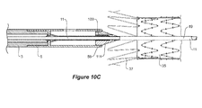
capsule assembly 5 can be used, the interface between astent graft 35 and theintroducer 1 is shown in more detail inFigures 10A, 10B and10C . These Figures show in detailed cross-section a portion of a stentgraft delivery device 1 according to an embodiment of the present invention.Figure 10A is similar to that ofFigure 1A but shows additional detail, including thestent graft 35 and its exposedstent 37. InFigure 10A , the exposedstent 37 is received into thecapsule cavity 55 and is prevented from being prematurely removed from thecapsule assembly 5 by the use of atrigger wire 39, which passes through thestent graft 35 to the outside of thecapsule assembly 5 and then enters thecapsule 5 throughaperture 41 in thecapsule tube 52. Thetrigger wire 39 then passes through one of thebends 43 of the exposedstent 37 and then through ahole 56 in theplug portion 110 and into thenose cone cavity 4 in thenose cone dilator 3. Thehole 56 is shown inFigure 6 . - In
Figure 10B , thetrigger wire 39 has been removed and thenose cone dilator 3 andcapsule assembly 5 have been advanced proximally by movement of theguide wire catheter 11, as indicated by thearrow 49 onFigure 10B with respect to thehandle 13. The exposedstent 37 is still partly retained in the capsule. Theplug portion 110 has, in effect, moved towards thedistal end 59 of thecapsule tube 52. - In
Figure 10C , thecapsule plug portion 110 is shown fully extended from thecapsule tube 52 and is locked in place by thetail lock 160 and theend stop 150. The interaction between thetail lock 160, or more specifically, the barb abutment surfaces 164, 264 shown onFigure 8B and the proximalcapsule end wall 53, provide a compressive resistance. Any relative movement between thecapsule tube 52 and thecapsule plug 110, once in the position shown inFigures 1B and10C , will be strongly resisted in compression. - The operation of the embodiment of the invention illustrated in
Figure 3 will now be described. - The environment in which the
capsule assembly 5 is typically used is within the aorta of a patient, proximal to an aortic aneurism. Blood pulses past thedelivery device 1 and, hence thecapsule assembly 5, as it tracks through what is often a torturous vasculature towards an incision in the femoral artery. - The
delivery system 1 is positioned such that thestent graft 35 is aligned in the area of treatment, which places thenose cone dilator 3 and thecapsule assembly 5 proximal to the aneurism. At this point, various stent graft deployment steps are taken as is known in the art and it is only when theproximal stent 37 is ready for deployment, that thecapsule retriever 100 of thecapsule assembly 5 is activated, as will now be described. - The proximal exposed
stent 37 is deployed by removing thetrigger wire 39 end by pulling thetrigger wire 39 out of thetrigger wire lumen 120. Thepin vice arrangement 15, shown inFigure 2C , is then released. Theguide wire catheter 11 is then pushed at its distal end in a proximal direction. This movement in the direction ofarrow 49, as shown inFigure 10B , slides thecapsule tube 52 off the exposedstent 37 and is stopped when the capsuleplug tail portion 130 snaps into locking engagement with the proximalcapsule end wall 53 into the position shown inFigure 1B . - The locking mechanism in the form of pin vice 15 (as is shown in
Figure 3 ) is reactivated to lock thesleeve 19 and theguide wire catheter 11 together and then thenose cone dilator 3 andcapsule assembly 5 are retrieved as the distal attachment of thestent graft 35 is removed, docking thecapsule plug portion 110 with the proximal end of the pusher catheter 29 (these components are most clearly shown inFigure 3 ). This docked position is shown inFigure 2B . - In some applications the
capsule assembly 5 will form part of a more complex introducer than theintroducer 1 illustrated infigure 3 . For instance, an introducer with a two-part handle such as that shown and described in the applicant's earlier patent publication numberUS2010/0198328 (Hartley et al. ), titled Preloaded Stent Graft Delivery Device, can be used for deployment of fenestrated stent grafts that have fenestrations for branch vessels (the contents of this publication is hereby incorporated by reference in its entirety). Such a handle may resemble the handle shown inFigure 2C with lockingscrews pusher catheter 29 is retrieved through thesheath 90 leaving thenose cone dilator 3 andcapsule assembly 5 in place until the handle pieces come together. Finally, thenose cone dilator 3 andcapsule assembly 5 are removed via thesheath 90 by pulling them through theCaptor™ valve 33. - It has been found that the
capsule assembly 5 offers a number of advantages over earlier capsule assembly arrangements. For instance, thecapsule plug portion 110 is more stable and will not readily dislodge even as thedelivery device 1 is manipulated through torturous vasculature systems. Embodiments of the invention described above are relatively simple and easy to manufacture with tight tolerance being less important as compared to prior art designs. With the embodiments of the invention described above, it is extremely unlikely, if not impossible, for theplug portion 110 to come all of the way out of thecapsule tube 52. Again, this provides advantages over prior art devices. With embodiments of the invention that include thetail lock 160 described above, thecapsule assembly 5 does not rely on tension in the (PEEK) plugsleeve 19 to hold thecapsule plug portion 110 in its retrieval position, as is shown inFigure 1B . - Throughout the specification and the claims that follow, unless the context requires otherwise, the words "comprise" and "include" and variations such as "comprising" and "including" will be understood to imply the inclusion of a stated integer or group of integers, but not the exclusion of any other integer or group of integers.
- The reference to any prior art in this specification is not, and should not be taken as, an acknowledgement of any form of suggestion that such prior art forms part of the common general knowledge.
- It will be appreciated by those skilled in the art that the invention is not restricted in its use to the particular application described. Neither is the present invention restricted in its preferred embodiment with regard to the particular elements and/or features described or depicted herein. It will be appreciated that the invention is not limited to the embodiment or embodiments disclosed, but is capable of numerous rearrangements, modifications and substitutions without departing from the scope of the invention as set forth and defined by the following claims.
Claims (14)
- A capsule assembly for a medical device introducer, the capsule assembly comprising:a capsule retriever having a plug portion and a tail portion, the plug portion having a lead-in surface, the tail portion having an elongate body extending proximally from the plug portion to an end stop receiver;a capsule tube having an end stop feature at a proximal end thereof and terminating in a distal end; anda capsule cavity inside the capsule tube, a proximal end of a medical device being receivable in the cavity,wherein the capsule tube is slidably movable with respect to the capsule retriever from a first position in which the distal end of the capsule tube surrounds an opening into the capsule cavity to a second position in which the distal end of the capsule tube is adjacent to the lead-in surface of the plug portion and the end stop feature and end stop feature receiver are engaged.
- The capsule assembly as claimed in claim 1, wherein the end stop feature comprises a capsule wall, the capsule wall defining a wall aperture.
- The capsule assembly as claimed in claim 1 or 2, wherein the tail portion comprises a tail lock, the tail lock being arranged to prevent the lead-in surface of the plug portion re-entering the capsule tube from the second position.
- The capsule assembly as claimed in claims 2 and 3, wherein the tail lock comprises a barb, the barb extending proximally from the elongate body and terminating with a barb abutment surface, the barb abutment surface being resiliently moveable from a relaxed position to a deflected position, the deflected position enabling the abutment surface to pass through the wall aperture.
- The capsule assembly as claimed in claim 4 wherein, when the capsule tube is in the second position, the abutment surface is prevented from re-entering the wall aperture by abutment of the abutment surface against the end wall.
- The capsule assembly as claimed in claim 5, wherein the tail portion comprises a tail tube, the tail tube defining a tail lumen.
- The capsule assembly as claimed in claim 6, wherein the tail tube comprises a pair of opposed resiliently flexible tabs, each tab forming a said barb.
- The capsule assembly as claimed in claim 7, wherein the tail tube comprises a pair of opposed flanges, the flanges forming said end stop receiver.
- The capsule assembly as claimed in claim 8, wherein the barbs and the flanges and the tube are a unitary assembly.
- The capsule assembly as claimed in any preceding claim, wherein the lead-in surface includes a frusto-conical portion.
- The capsule assembly as claimed in any preceding claim, wherein the plug portion comprises a landing surface proximally adjacent to the lead-in surface, the landing surface slidably engaging the capsule tube.
- A system for delivering and deploying an expandable medical device, the system comprising:a sheath having a lumen;a delivery catheter including a longitudinally extending guide wire catheter, the delivery catheter being slidably disposed within the lumen of the sheath;an expandable medical device disposed on a proximal portion of the delivery catheter;a haemostatic device sealingly engaging the delivery catheter; anda capsule assembly at the proximal portion of the delivery catheter, the capsule assemblybeing according to any preceding claim.
- The system as claimed in claim 12 comprising a plug sleeve joined to the plug portion and mounted coaxially around the guide wire catheter, the guide wire catheter being slidably movable with respect to the plug sleeve and the capsule plug portion from the first position to the second position.
- A medical device introducer comprising a nose cone dilator and a capsule assembly at a proximal end, a guide wire catheter extending distally from the nose cone dilator though the capsule assembly, a sheath and a handle, to a distal end, the capsule assembly being as defined by any of claims 1 to 11.
Applications Claiming Priority (1)
| Application Number | Priority Date | Filing Date | Title |
|---|---|---|---|
| AU2014200686A AU2014200686B1 (en) | 2014-02-05 | 2014-02-05 | An endograft introducer and a capsule assembly for an endograft introducer |
Publications (2)
| Publication Number | Publication Date |
|---|---|
| EP2921144A1 true EP2921144A1 (en) | 2015-09-23 |
| EP2921144B1 EP2921144B1 (en) | 2016-11-16 |
Family
ID=51221212
Family Applications (1)
| Application Number | Title | Priority Date | Filing Date |
|---|---|---|---|
| EP15275015.4A Active EP2921144B1 (en) | 2014-02-05 | 2015-01-15 | A capsule assembly for a medical device introducer |
Country Status (3)
| Country | Link |
|---|---|
| US (1) | US9867729B2 (en) |
| EP (1) | EP2921144B1 (en) |
| AU (1) | AU2014200686B1 (en) |
Families Citing this family (5)
| Publication number | Priority date | Publication date | Assignee | Title |
|---|---|---|---|---|
| US10603198B2 (en) | 2016-09-09 | 2020-03-31 | Cook Medical Technologies Llc | Prosthesis deployment system and method |
| US11786387B2 (en) | 2017-11-24 | 2023-10-17 | Ptmc Institute | Stent graft transport device |
| AU2018282309B1 (en) * | 2018-12-19 | 2019-07-11 | Cook Medical Technologies Llc | An endovascular delivery device having an improved top-cap assembly |
| US11383066B2 (en) * | 2019-02-05 | 2022-07-12 | Virginia Commonwealth University | Guidewire systems and methods for preventing wire advancement into the body during catheterization |
| CN116407385A (en) * | 2021-12-31 | 2023-07-11 | 先健科技(深圳)有限公司 | Conveyor |
Citations (2)
| Publication number | Priority date | Publication date | Assignee | Title |
|---|---|---|---|---|
| WO2009148602A1 (en) * | 2008-06-04 | 2009-12-10 | William A. Cook Australia Pty. Ltd. | Introducer |
| US20100198328A1 (en) | 2009-02-02 | 2010-08-05 | William A. Cook Australia Pty. Ltd. | Preloaded Stent Graft Delivery Device |
Family Cites Families (11)
| Publication number | Priority date | Publication date | Assignee | Title |
|---|---|---|---|---|
| US7651505B2 (en) * | 2002-06-17 | 2010-01-26 | Senorx, Inc. | Plugged tip delivery for marker placement |
| US7226464B2 (en) * | 2001-03-01 | 2007-06-05 | Scimed Life Systems, Inc. | Intravascular filter retrieval device having an actuatable dilator tip |
| DE602006009963D1 (en) * | 2005-11-17 | 2009-12-03 | Peritec Biosciences Ltd | DEVICE AND METHOD FOR DISTRIBUTING A DRESSED INTRALUMINAL PROSTHESIS |
| WO2007142962A2 (en) | 2006-06-02 | 2007-12-13 | William A. Cook Australia Pty. Ltd. | Multi-port delivery device |
| DE602007004493D1 (en) * | 2006-07-24 | 2010-03-11 | Cook Inc | INTRODUCTION AID FOR A MEDICAL DEVICE WITH ANDOCK ARRANGEMENT |
| EP2397108B1 (en) * | 2006-09-08 | 2013-08-07 | Edwards Lifesciences Corporation | Apparatus for treating a defective heart valve |
| DE102006053748B3 (en) | 2006-11-09 | 2008-04-10 | Jotec Gmbh | Insert system for inserting and releasing e.g. endovascular stent, has fixing system with cover unit including pivoting units axially extending in proximal direction of insert system, and retaining unit arranged proximal to cover unit |
| WO2009094490A1 (en) | 2008-01-24 | 2009-07-30 | Boston Scientific Scimed, Inc. | Apparatus and method for loading and delivering a stent having improved handles to control relative catheter component movement |
| US8986361B2 (en) * | 2008-10-17 | 2015-03-24 | Medtronic Corevalve, Inc. | Delivery system for deployment of medical devices |
| AU2010202487B1 (en) * | 2010-06-15 | 2011-07-28 | Cook Incorporated | Pre-loaded multiport delivery device |
| JP6294669B2 (en) * | 2011-03-01 | 2018-03-14 | エンドロジックス、インク | Catheter system and method of use thereof |
-
2014
- 2014-02-05 AU AU2014200686A patent/AU2014200686B1/en active Active
-
2015
- 2015-01-15 EP EP15275015.4A patent/EP2921144B1/en active Active
- 2015-02-03 US US14/612,682 patent/US9867729B2/en active Active
Patent Citations (2)
| Publication number | Priority date | Publication date | Assignee | Title |
|---|---|---|---|---|
| WO2009148602A1 (en) * | 2008-06-04 | 2009-12-10 | William A. Cook Australia Pty. Ltd. | Introducer |
| US20100198328A1 (en) | 2009-02-02 | 2010-08-05 | William A. Cook Australia Pty. Ltd. | Preloaded Stent Graft Delivery Device |
Also Published As
| Publication number | Publication date |
|---|---|
| AU2014200686B1 (en) | 2014-06-26 |
| US20150216694A1 (en) | 2015-08-06 |
| US9867729B2 (en) | 2018-01-16 |
| EP2921144B1 (en) | 2016-11-16 |
Similar Documents
| Publication | Publication Date | Title |
|---|---|---|
| US8876879B2 (en) | Introducer | |
| US9060895B2 (en) | Rotational controlled deployment device | |
| US7736385B2 (en) | Exchangeable delivery system with distal protection | |
| US8414636B2 (en) | Introducer with ratchet handle drive | |
| EP2366362B1 (en) | Deploying medical implants | |
| EP2043566B1 (en) | Medical device introducer with docking arrangement | |
| US9867729B2 (en) | Endograft introducer and a capsule assembly for an endograft introducer | |
| US20040098079A1 (en) | Thoracic aortic stent graft deployment device | |
| EP3238659A1 (en) | Pre-loaded multiport delivery device | |
| US8663302B2 (en) | Delivery system ejection component and method | |
| US8414640B2 (en) | Delivery system ejection component and method | |
| US9510963B2 (en) | Endograft introducer and a capsule assembly for an endograft introducer | |
| US11141297B2 (en) | Endovascular delivery device having an improved top-cap assembly | |
| EP3510977A1 (en) | An endoluminal delivery device assembly | |
| EP3064177B1 (en) | Delivery device with an extension sheath |
Legal Events
| Date | Code | Title | Description |
|---|---|---|---|
| PUAI | Public reference made under article 153(3) epc to a published international application that has entered the european phase |
Free format text: ORIGINAL CODE: 0009012 |
|
| AK | Designated contracting states |
Kind code of ref document: A1 Designated state(s): AL AT BE BG CH CY CZ DE DK EE ES FI FR GB GR HR HU IE IS IT LI LT LU LV MC MK MT NL NO PL PT RO RS SE SI SK SM TR |
|
| AX | Request for extension of the european patent |
Extension state: BA ME |
|
| 17P | Request for examination filed |
Effective date: 20160118 |
|
| RBV | Designated contracting states (corrected) |
Designated state(s): AL AT BE BG CH CY CZ DE DK EE ES FI FR GB GR HR HU IE IS IT LI LT LU LV MC MK MT NL NO PL PT RO RS SE SI SK SM TR |
|
| GRAP | Despatch of communication of intention to grant a patent |
Free format text: ORIGINAL CODE: EPIDOSNIGR1 |
|
| INTG | Intention to grant announced |
Effective date: 20160719 |
|
| RIN1 | Information on inventor provided before grant (corrected) |
Inventor name: O'BRIEN, DAVID SEAN Inventor name: ROEDER, BLAYNE A. Inventor name: HARTLEY, DAVID ERNEST Inventor name: DUCKE, WERNER |
|
| GRAS | Grant fee paid |
Free format text: ORIGINAL CODE: EPIDOSNIGR3 |
|
| GRAA | (expected) grant |
Free format text: ORIGINAL CODE: 0009210 |
|
| AK | Designated contracting states |
Kind code of ref document: B1 Designated state(s): AL AT BE BG CH CY CZ DE DK EE ES FI FR GB GR HR HU IE IS IT LI LT LU LV MC MK MT NL NO PL PT RO RS SE SI SK SM TR |
|
| REG | Reference to a national code |
Ref country code: GB Ref legal event code: FG4D |
|
| REG | Reference to a national code |
Ref country code: CH Ref legal event code: EP |
|
| REG | Reference to a national code |
Ref country code: IE Ref legal event code: FG4D |
|
| REG | Reference to a national code |
Ref country code: AT Ref legal event code: REF Ref document number: 845175 Country of ref document: AT Kind code of ref document: T Effective date: 20161215 |
|
| REG | Reference to a national code |
Ref country code: DE Ref legal event code: R096 Ref document number: 602015000738 Country of ref document: DE |
|
| PG25 | Lapsed in a contracting state [announced via postgrant information from national office to epo] |
Ref country code: LV Free format text: LAPSE BECAUSE OF FAILURE TO SUBMIT A TRANSLATION OF THE DESCRIPTION OR TO PAY THE FEE WITHIN THE PRESCRIBED TIME-LIMIT Effective date: 20161116 |
|
| REG | Reference to a national code |
Ref country code: NL Ref legal event code: MP Effective date: 20161116 |
|
| REG | Reference to a national code |
Ref country code: LT Ref legal event code: MG4D |
|
| REG | Reference to a national code |
Ref country code: AT Ref legal event code: MK05 Ref document number: 845175 Country of ref document: AT Kind code of ref document: T Effective date: 20161116 |
|
| PG25 | Lapsed in a contracting state [announced via postgrant information from national office to epo] |
Ref country code: NO Free format text: LAPSE BECAUSE OF FAILURE TO SUBMIT A TRANSLATION OF THE DESCRIPTION OR TO PAY THE FEE WITHIN THE PRESCRIBED TIME-LIMIT Effective date: 20170216 Ref country code: GR Free format text: LAPSE BECAUSE OF FAILURE TO SUBMIT A TRANSLATION OF THE DESCRIPTION OR TO PAY THE FEE WITHIN THE PRESCRIBED TIME-LIMIT Effective date: 20170217 Ref country code: LT Free format text: LAPSE BECAUSE OF FAILURE TO SUBMIT A TRANSLATION OF THE DESCRIPTION OR TO PAY THE FEE WITHIN THE PRESCRIBED TIME-LIMIT Effective date: 20161116 Ref country code: SE Free format text: LAPSE BECAUSE OF FAILURE TO SUBMIT A TRANSLATION OF THE DESCRIPTION OR TO PAY THE FEE WITHIN THE PRESCRIBED TIME-LIMIT Effective date: 20161116 Ref country code: NL Free format text: LAPSE BECAUSE OF FAILURE TO SUBMIT A TRANSLATION OF THE DESCRIPTION OR TO PAY THE FEE WITHIN THE PRESCRIBED TIME-LIMIT Effective date: 20161116 |
|
| PG25 | Lapsed in a contracting state [announced via postgrant information from national office to epo] |
Ref country code: FI Free format text: LAPSE BECAUSE OF FAILURE TO SUBMIT A TRANSLATION OF THE DESCRIPTION OR TO PAY THE FEE WITHIN THE PRESCRIBED TIME-LIMIT Effective date: 20161116 Ref country code: BE Free format text: LAPSE BECAUSE OF NON-PAYMENT OF DUE FEES Effective date: 20170131 Ref country code: HR Free format text: LAPSE BECAUSE OF FAILURE TO SUBMIT A TRANSLATION OF THE DESCRIPTION OR TO PAY THE FEE WITHIN THE PRESCRIBED TIME-LIMIT Effective date: 20161116 Ref country code: PL Free format text: LAPSE BECAUSE OF FAILURE TO SUBMIT A TRANSLATION OF THE DESCRIPTION OR TO PAY THE FEE WITHIN THE PRESCRIBED TIME-LIMIT Effective date: 20161116 Ref country code: PT Free format text: LAPSE BECAUSE OF FAILURE TO SUBMIT A TRANSLATION OF THE DESCRIPTION OR TO PAY THE FEE WITHIN THE PRESCRIBED TIME-LIMIT Effective date: 20170316 Ref country code: AT Free format text: LAPSE BECAUSE OF FAILURE TO SUBMIT A TRANSLATION OF THE DESCRIPTION OR TO PAY THE FEE WITHIN THE PRESCRIBED TIME-LIMIT Effective date: 20161116 Ref country code: ES Free format text: LAPSE BECAUSE OF FAILURE TO SUBMIT A TRANSLATION OF THE DESCRIPTION OR TO PAY THE FEE WITHIN THE PRESCRIBED TIME-LIMIT Effective date: 20161116 Ref country code: RS Free format text: LAPSE BECAUSE OF FAILURE TO SUBMIT A TRANSLATION OF THE DESCRIPTION OR TO PAY THE FEE WITHIN THE PRESCRIBED TIME-LIMIT Effective date: 20161116 |
|
| PG25 | Lapsed in a contracting state [announced via postgrant information from national office to epo] |
Ref country code: RO Free format text: LAPSE BECAUSE OF FAILURE TO SUBMIT A TRANSLATION OF THE DESCRIPTION OR TO PAY THE FEE WITHIN THE PRESCRIBED TIME-LIMIT Effective date: 20161116 Ref country code: EE Free format text: LAPSE BECAUSE OF FAILURE TO SUBMIT A TRANSLATION OF THE DESCRIPTION OR TO PAY THE FEE WITHIN THE PRESCRIBED TIME-LIMIT Effective date: 20161116 Ref country code: DK Free format text: LAPSE BECAUSE OF FAILURE TO SUBMIT A TRANSLATION OF THE DESCRIPTION OR TO PAY THE FEE WITHIN THE PRESCRIBED TIME-LIMIT Effective date: 20161116 Ref country code: CZ Free format text: LAPSE BECAUSE OF FAILURE TO SUBMIT A TRANSLATION OF THE DESCRIPTION OR TO PAY THE FEE WITHIN THE PRESCRIBED TIME-LIMIT Effective date: 20161116 Ref country code: SK Free format text: LAPSE BECAUSE OF FAILURE TO SUBMIT A TRANSLATION OF THE DESCRIPTION OR TO PAY THE FEE WITHIN THE PRESCRIBED TIME-LIMIT Effective date: 20161116 |
|
| REG | Reference to a national code |
Ref country code: DE Ref legal event code: R097 Ref document number: 602015000738 Country of ref document: DE |
|
| PG25 | Lapsed in a contracting state [announced via postgrant information from national office to epo] |
Ref country code: SM Free format text: LAPSE BECAUSE OF FAILURE TO SUBMIT A TRANSLATION OF THE DESCRIPTION OR TO PAY THE FEE WITHIN THE PRESCRIBED TIME-LIMIT Effective date: 20161116 Ref country code: BE Free format text: LAPSE BECAUSE OF FAILURE TO SUBMIT A TRANSLATION OF THE DESCRIPTION OR TO PAY THE FEE WITHIN THE PRESCRIBED TIME-LIMIT Effective date: 20161116 Ref country code: BG Free format text: LAPSE BECAUSE OF FAILURE TO SUBMIT A TRANSLATION OF THE DESCRIPTION OR TO PAY THE FEE WITHIN THE PRESCRIBED TIME-LIMIT Effective date: 20170216 Ref country code: IT Free format text: LAPSE BECAUSE OF FAILURE TO SUBMIT A TRANSLATION OF THE DESCRIPTION OR TO PAY THE FEE WITHIN THE PRESCRIBED TIME-LIMIT Effective date: 20161116 |
|
| PLBE | No opposition filed within time limit |
Free format text: ORIGINAL CODE: 0009261 |
|
| STAA | Information on the status of an ep patent application or granted ep patent |
Free format text: STATUS: NO OPPOSITION FILED WITHIN TIME LIMIT |
|
| PG25 | Lapsed in a contracting state [announced via postgrant information from national office to epo] |
Ref country code: MC Free format text: LAPSE BECAUSE OF FAILURE TO SUBMIT A TRANSLATION OF THE DESCRIPTION OR TO PAY THE FEE WITHIN THE PRESCRIBED TIME-LIMIT Effective date: 20161116 |
|
| 26N | No opposition filed |
Effective date: 20170817 |
|
| REG | Reference to a national code |
Ref country code: FR Ref legal event code: ST Effective date: 20170929 |
|
| PG25 | Lapsed in a contracting state [announced via postgrant information from national office to epo] |
Ref country code: FR Free format text: LAPSE BECAUSE OF NON-PAYMENT OF DUE FEES Effective date: 20170131 |
|
| PG25 | Lapsed in a contracting state [announced via postgrant information from national office to epo] |
Ref country code: SI Free format text: LAPSE BECAUSE OF FAILURE TO SUBMIT A TRANSLATION OF THE DESCRIPTION OR TO PAY THE FEE WITHIN THE PRESCRIBED TIME-LIMIT Effective date: 20161116 Ref country code: LU Free format text: LAPSE BECAUSE OF NON-PAYMENT OF DUE FEES Effective date: 20170115 |
|
| REG | Reference to a national code |
Ref country code: CH Ref legal event code: PL |
|
| PG25 | Lapsed in a contracting state [announced via postgrant information from national office to epo] |
Ref country code: MT Free format text: LAPSE BECAUSE OF NON-PAYMENT OF DUE FEES Effective date: 20170115 |
|
| PG25 | Lapsed in a contracting state [announced via postgrant information from national office to epo] |
Ref country code: LI Free format text: LAPSE BECAUSE OF NON-PAYMENT OF DUE FEES Effective date: 20180131 Ref country code: CH Free format text: LAPSE BECAUSE OF NON-PAYMENT OF DUE FEES Effective date: 20180131 |
|
| PG25 | Lapsed in a contracting state [announced via postgrant information from national office to epo] |
Ref country code: HU Free format text: LAPSE BECAUSE OF FAILURE TO SUBMIT A TRANSLATION OF THE DESCRIPTION OR TO PAY THE FEE WITHIN THE PRESCRIBED TIME-LIMIT; INVALID AB INITIO Effective date: 20150115 |
|
| PG25 | Lapsed in a contracting state [announced via postgrant information from national office to epo] |
Ref country code: CY Free format text: LAPSE BECAUSE OF FAILURE TO SUBMIT A TRANSLATION OF THE DESCRIPTION OR TO PAY THE FEE WITHIN THE PRESCRIBED TIME-LIMIT Effective date: 20161116 |
|
| PG25 | Lapsed in a contracting state [announced via postgrant information from national office to epo] |
Ref country code: MK Free format text: LAPSE BECAUSE OF FAILURE TO SUBMIT A TRANSLATION OF THE DESCRIPTION OR TO PAY THE FEE WITHIN THE PRESCRIBED TIME-LIMIT Effective date: 20161116 |
|
| PG25 | Lapsed in a contracting state [announced via postgrant information from national office to epo] |
Ref country code: TR Free format text: LAPSE BECAUSE OF FAILURE TO SUBMIT A TRANSLATION OF THE DESCRIPTION OR TO PAY THE FEE WITHIN THE PRESCRIBED TIME-LIMIT Effective date: 20161116 |
|
| PG25 | Lapsed in a contracting state [announced via postgrant information from national office to epo] |
Ref country code: AL Free format text: LAPSE BECAUSE OF FAILURE TO SUBMIT A TRANSLATION OF THE DESCRIPTION OR TO PAY THE FEE WITHIN THE PRESCRIBED TIME-LIMIT Effective date: 20161116 Ref country code: IS Free format text: LAPSE BECAUSE OF FAILURE TO SUBMIT A TRANSLATION OF THE DESCRIPTION OR TO PAY THE FEE WITHIN THE PRESCRIBED TIME-LIMIT Effective date: 20170316 |
|
| PGFP | Annual fee paid to national office [announced via postgrant information from national office to epo] |
Ref country code: DE Payment date: 20221215 Year of fee payment: 9 |
|
| P01 | Opt-out of the competence of the unified patent court (upc) registered |
Effective date: 20230602 |
|
| PGFP | Annual fee paid to national office [announced via postgrant information from national office to epo] |
Ref country code: GB Payment date: 20231218 Year of fee payment: 10 |
|
| PGFP | Annual fee paid to national office [announced via postgrant information from national office to epo] |
Ref country code: IE Payment date: 20231228 Year of fee payment: 10 |