EP2921126A1 - Laser ablation device - Google Patents
Laser ablation device Download PDFInfo
- Publication number
- EP2921126A1 EP2921126A1 EP13855396.1A EP13855396A EP2921126A1 EP 2921126 A1 EP2921126 A1 EP 2921126A1 EP 13855396 A EP13855396 A EP 13855396A EP 2921126 A1 EP2921126 A1 EP 2921126A1
- Authority
- EP
- European Patent Office
- Prior art keywords
- fiber
- laser
- piezoelectric elements
- drive unit
- ablation device
- Prior art date
- Legal status (The legal status is an assumption and is not a legal conclusion. Google has not performed a legal analysis and makes no representation as to the accuracy of the status listed.)
- Granted
Links
- 238000000608 laser ablation Methods 0.000 title claims abstract description 42
- 239000000835 fiber Substances 0.000 claims abstract description 94
- 238000003780 insertion Methods 0.000 claims abstract description 24
- 230000037431 insertion Effects 0.000 claims abstract description 24
- 230000033001 locomotion Effects 0.000 claims description 6
- 230000005855 radiation Effects 0.000 abstract description 59
- 210000001519 tissue Anatomy 0.000 description 8
- 230000003321 amplification Effects 0.000 description 6
- 238000012986 modification Methods 0.000 description 6
- 230000004048 modification Effects 0.000 description 6
- 238000003199 nucleic acid amplification method Methods 0.000 description 6
- 230000000694 effects Effects 0.000 description 5
- 238000011287 therapeutic dose Methods 0.000 description 3
- 230000006793 arrhythmia Effects 0.000 description 2
- 206010003119 arrhythmia Diseases 0.000 description 2
- 238000000034 method Methods 0.000 description 2
- 238000006243 chemical reaction Methods 0.000 description 1
- 230000005674 electromagnetic induction Effects 0.000 description 1
- 238000002324 minimally invasive surgery Methods 0.000 description 1
- 210000003516 pericardium Anatomy 0.000 description 1
Images








Classifications
-
- A—HUMAN NECESSITIES
- A61—MEDICAL OR VETERINARY SCIENCE; HYGIENE
- A61B—DIAGNOSIS; SURGERY; IDENTIFICATION
- A61B18/00—Surgical instruments, devices or methods for transferring non-mechanical forms of energy to or from the body
- A61B18/18—Surgical instruments, devices or methods for transferring non-mechanical forms of energy to or from the body by applying electromagnetic radiation, e.g. microwaves
- A61B18/20—Surgical instruments, devices or methods for transferring non-mechanical forms of energy to or from the body by applying electromagnetic radiation, e.g. microwaves using laser
- A61B18/22—Surgical instruments, devices or methods for transferring non-mechanical forms of energy to or from the body by applying electromagnetic radiation, e.g. microwaves using laser the beam being directed along or through a flexible conduit, e.g. an optical fibre; Couplings or hand-pieces therefor
- A61B18/24—Surgical instruments, devices or methods for transferring non-mechanical forms of energy to or from the body by applying electromagnetic radiation, e.g. microwaves using laser the beam being directed along or through a flexible conduit, e.g. an optical fibre; Couplings or hand-pieces therefor with a catheter
-
- A—HUMAN NECESSITIES
- A61—MEDICAL OR VETERINARY SCIENCE; HYGIENE
- A61B—DIAGNOSIS; SURGERY; IDENTIFICATION
- A61B18/00—Surgical instruments, devices or methods for transferring non-mechanical forms of energy to or from the body
- A61B2018/00053—Mechanical features of the instrument of device
- A61B2018/00184—Moving parts
- A61B2018/0019—Moving parts vibrating
-
- A—HUMAN NECESSITIES
- A61—MEDICAL OR VETERINARY SCIENCE; HYGIENE
- A61B—DIAGNOSIS; SURGERY; IDENTIFICATION
- A61B18/00—Surgical instruments, devices or methods for transferring non-mechanical forms of energy to or from the body
- A61B2018/00053—Mechanical features of the instrument of device
- A61B2018/00184—Moving parts
- A61B2018/00202—Moving parts rotating
- A61B2018/00208—Moving parts rotating actively driven, e.g. by a motor
-
- A—HUMAN NECESSITIES
- A61—MEDICAL OR VETERINARY SCIENCE; HYGIENE
- A61B—DIAGNOSIS; SURGERY; IDENTIFICATION
- A61B18/00—Surgical instruments, devices or methods for transferring non-mechanical forms of energy to or from the body
- A61B2018/00315—Surgical instruments, devices or methods for transferring non-mechanical forms of energy to or from the body for treatment of particular body parts
- A61B2018/00345—Vascular system
- A61B2018/00351—Heart
-
- A—HUMAN NECESSITIES
- A61—MEDICAL OR VETERINARY SCIENCE; HYGIENE
- A61B—DIAGNOSIS; SURGERY; IDENTIFICATION
- A61B18/00—Surgical instruments, devices or methods for transferring non-mechanical forms of energy to or from the body
- A61B2018/00571—Surgical instruments, devices or methods for transferring non-mechanical forms of energy to or from the body for achieving a particular surgical effect
- A61B2018/00577—Ablation
-
- A—HUMAN NECESSITIES
- A61—MEDICAL OR VETERINARY SCIENCE; HYGIENE
- A61B—DIAGNOSIS; SURGERY; IDENTIFICATION
- A61B18/00—Surgical instruments, devices or methods for transferring non-mechanical forms of energy to or from the body
- A61B2018/00571—Surgical instruments, devices or methods for transferring non-mechanical forms of energy to or from the body for achieving a particular surgical effect
- A61B2018/00595—Cauterization
-
- A—HUMAN NECESSITIES
- A61—MEDICAL OR VETERINARY SCIENCE; HYGIENE
- A61B—DIAGNOSIS; SURGERY; IDENTIFICATION
- A61B18/00—Surgical instruments, devices or methods for transferring non-mechanical forms of energy to or from the body
- A61B18/18—Surgical instruments, devices or methods for transferring non-mechanical forms of energy to or from the body by applying electromagnetic radiation, e.g. microwaves
- A61B18/20—Surgical instruments, devices or methods for transferring non-mechanical forms of energy to or from the body by applying electromagnetic radiation, e.g. microwaves using laser
- A61B2018/2035—Beam shaping or redirecting; Optical components therefor
- A61B2018/20351—Scanning mechanisms
-
- A—HUMAN NECESSITIES
- A61—MEDICAL OR VETERINARY SCIENCE; HYGIENE
- A61B—DIAGNOSIS; SURGERY; IDENTIFICATION
- A61B18/00—Surgical instruments, devices or methods for transferring non-mechanical forms of energy to or from the body
- A61B18/18—Surgical instruments, devices or methods for transferring non-mechanical forms of energy to or from the body by applying electromagnetic radiation, e.g. microwaves
- A61B18/20—Surgical instruments, devices or methods for transferring non-mechanical forms of energy to or from the body by applying electromagnetic radiation, e.g. microwaves using laser
- A61B2018/2035—Beam shaping or redirecting; Optical components therefor
- A61B2018/20351—Scanning mechanisms
- A61B2018/20357—Scanning mechanisms by movable optical fibre end
-
- A—HUMAN NECESSITIES
- A61—MEDICAL OR VETERINARY SCIENCE; HYGIENE
- A61B—DIAGNOSIS; SURGERY; IDENTIFICATION
- A61B18/00—Surgical instruments, devices or methods for transferring non-mechanical forms of energy to or from the body
- A61B18/18—Surgical instruments, devices or methods for transferring non-mechanical forms of energy to or from the body by applying electromagnetic radiation, e.g. microwaves
- A61B18/20—Surgical instruments, devices or methods for transferring non-mechanical forms of energy to or from the body by applying electromagnetic radiation, e.g. microwaves using laser
- A61B2018/2035—Beam shaping or redirecting; Optical components therefor
- A61B2018/20351—Scanning mechanisms
- A61B2018/20359—Scanning mechanisms by movable mirrors, e.g. galvanometric
-
- A—HUMAN NECESSITIES
- A61—MEDICAL OR VETERINARY SCIENCE; HYGIENE
- A61B—DIAGNOSIS; SURGERY; IDENTIFICATION
- A61B18/00—Surgical instruments, devices or methods for transferring non-mechanical forms of energy to or from the body
- A61B18/18—Surgical instruments, devices or methods for transferring non-mechanical forms of energy to or from the body by applying electromagnetic radiation, e.g. microwaves
- A61B18/20—Surgical instruments, devices or methods for transferring non-mechanical forms of energy to or from the body by applying electromagnetic radiation, e.g. microwaves using laser
- A61B18/22—Surgical instruments, devices or methods for transferring non-mechanical forms of energy to or from the body by applying electromagnetic radiation, e.g. microwaves using laser the beam being directed along or through a flexible conduit, e.g. an optical fibre; Couplings or hand-pieces therefor
- A61B2018/2205—Characteristics of fibres
Definitions
- the present invention relates to a laser ablation device.
- a laser ablation catheter with which laser light is radiated onto affected tissue from an insertion portion that emits laser light having high-density energy, thus cauterizing the affected tissue has been known (for example, PTL 1).
- the laser ablation catheter is used mainly to perform arrhythmia treatment and has the advantage, for patients, that only a minimum region into which the laser ablation catheter can be inserted needs to be incised, thereby making it possible to cauterize an affected area, which allows minimally invasive surgery to be performed.
- the present invention has been made in view of the above-described circumstances, and an object thereof is to provide a laser ablation device that prevents local excessive laser radiation and that performs uniform laser radiation in a target treatment region.
- the present invention provides the following solutions.
- the present invention provides a laser ablation device including: a light source that emits laser light for cauterizing an affected area; a fiber that is provided in an insertion portion and that guides the laser light emitted from the light source to radiate the laser light from an insertion-portion distal end; and a first drive unit that is provided on the fiber and that vibrates the fiber with a first period.
- laser light emitted from the light source is guided by the fiber, which is provided in the insertion portion, and the fiber emits the laser light from the insertion-portion distal end.
- the laser light emitted from the insertion-portion distal end specifically, from the emitting end of the fiber, is radiated onto the affected area in a linear fashion, because the laser light is periodically vibrated by the first drive unit, the laser light can be radiated uniformly onto a predetermined area without being radiated onto a fixed point. Therefore, it is possible to perform uniform laser radiation in a target treatment region and also to prevent local excessive laser radiation.
- the first period and the second period are set to different periods or also to the same period.
- the amplitude produced by the second drive unit be larger than the amplitude produced by the first drive unit.
- the first drive unit can perform relatively-fine laser-light radiation
- the second drive unit can perform relatively-rough radiation, it is possible to evenly perform uniform laser-light radiation on an affected area while expanding the laser-light radiation area as a whole.
- the first drive unit be provided closer to a distal end of the fiber than the second drive unit; and the second period be longer than the first period.
- the first drive unit be provided closer to a distal end of the fiber than the second drive unit; and the second period be a period n times (n is an integer) the first period.
- laser light can be radiated onto the affected area more uniformly.
- the fiber be made to perform rotational motions by the first drive unit and the second drive unit; and the number of rotations of the fiber due to the first drive unit be faster than the number of rotations of the fiber due to the second drive unit.
- laser light can be radiated onto the affected area more uniformly.
- the first drive unit and the second drive unit allow the fiber to perform a resonant motion, raster scanning, spiral scanning, and scanning obtained by combining different types of scanning. In this way, by allowing the resonant motion, the electro-mechanical conversion efficiency is enhanced, thus making it possible to reduce the voltage required to perform predetermined treatment.
- the shape of laser radiation area can be changed by changing the scanning method to raster scanning, spiral scanning, or the like, it is possible to achieve a reduction in radiation time and a reduction in the number of times radiation is performed, by selecting an appropriate scanning method in accordance with the shape of a treatment target.
- an advantageous effect is afforded in that it is possible to prevent local excessive laser radiation and to allow uniform laser radiation in a target treatment region.
- a laser ablation device 10 according to a first embodiment of the present invention will be described below with reference to the drawings.
- the laser ablation device 10 of this embodiment radiates laser light from an insertion portion, to be described later, onto affected tissue to cauterize the affected tissue, thereby performing treatment for arrhythmia etc., and includes an insertion portion 11 and a main portion 12.
- the insertion portion 11 to be inserted into the body of patients is a long bendable pipe conduit and includes a fiber 15 that guides laser light emitted from a light source, to be described later, and that radiates the laser light from an insertion-portion distal end and a motor 16 that is provided on the fiber 15 to vibrate the fiber 15 with a predetermined period.
- the fiber 15 is provided integrally with a shaft 16A of the motor 16 and guides laser light while rotating in conjunction with rotation of the motor 16.
- the shaft 16A has a hollow structure, and the fiber 15 passes through the shaft 16A.
- the shaft 16A of the motor 16 has a bent portion, so that the output of the motor 16 is made to be eccentric with respect to the axis of rotation.
- four ball bearings 16B are disposed in a distal end of the shaft 16A at equal-spaced intervals, the fiber 15 is in contact with the shaft 16A via the ball bearings 16B, and thus the fiber 15 is fixed to the shaft 16A.
- a lens 15A through which laser light emitted from an emitting end of the fiber 15 is transmitted is provided on a distal end surface of the insertion portion 11.
- the main portion 12 includes a light source section 17, a vibration control section 18 that controls the vibration of the fiber 15, and a control section 19 that controls the light source section 17 and the vibration control section 18.
- the light source section 17 includes an LD (laser diode) 17A that serves as the light source, which emits laser light for cauterizing an affected area, and an LD driving part 17B that drives the LD 17A.
- LD laser diode
- the vibration control section 18 has a motor driving part 18A that rotationally drives the motor 16 and a rotating-speed modulating part 18B that appropriately modulates the rotating speed of the motor 16.
- the distal end of the insertion portion 11 of the laser ablation device 10 is inserted up to the vicinity of an affected area.
- laser light is emitted from the LD 17A and enters an incident end of the fiber 15 that is located at a base end of the insertion portion 11.
- the laser light is guided by the fiber 15 to the distal end of the fiber 15 and is radiated from the emitting end of the fiber 15 onto the affected area via the lens 15A, which is provided at the distal end of the insertion portion 11.
- the fiber 15 is provided integrally with the shaft 16A of the motor 16 so as to guide the laser light while rotating in conjunction with rotation of the motor 16. Furthermore, because the shaft 16A of the motor 16 makes the output of the motor 16 eccentric with respect to the axis of rotation, when the motor 16 is rotationally driven by the motor driving part 18A, the laser light emitted from the fiber 15 is radiated onto the affected area while tracing a circular trajectory corresponding to the eccentric position of the shaft 16A.
- rotation of the motor 16 vibrates the fiber 15, which emits laser light, thereby making it also possible to vibrate the laser-light radiation trajectory, thus preventing laser light from being locally radiated onto the affected area and allowing uniform laser-light radiation while expanding the radiation region.
- a laser ablation device 30 according to a second embodiment of the present invention will be described below with reference to the drawings.
- identical reference signs are assigned to the same components as those in the above-described first embodiment, and a description thereof will be omitted.
- This embodiment mainly differs from the first embodiment in that piezoelectric elements 15B are provided symmetrically in four directions around the axis of the output end of the shaft 16A, as shown in Fig. 3 .
- the main portion 12 further includes a piezoelectric-element control section 20 that controls the piezoelectric elements, and the control section 19 controls the light source section 17, the vibration control section 18, and the piezoelectric-element control section 20.
- the piezoelectric-element control section 20 includes an AM modulation part 23 that supplies electric power to the piezoelectric elements 15B, a PLL control part 24 that adjusts the phases of modulated signals output from the AM modulation part 23 and the number of rotations of the motor 16, an AC-signal generating part 21 that generates AC signals to be supplied to the AM modulation part 23, and an amplification part 22 that amplifies the AC signals output from the AC-signal generating part 21.
- the fiber 15 is provided in the hollow shaft 16A, and the distal end of the fiber 15 is fixed to the shaft 16A by ball bearings 16B that are provided via an elastic member 16C. Contact points of the ball bearings 16B are located at the position of a node of a vibration of the elastic member.
- the piezoelectric elements 15B are provided symmetrically in four directions around the axis of the fiber 15 via the elastic member 16C and are composed of X-axis-driving piezoelectric elements and Y-axis-driving piezoelectric elements, the phases of the AC signals supplied from the AC-signal generating part 21 to the X-axis-driving piezoelectric elements and the Y-axis-driving piezoelectric elements are shifted by 90 degrees. Furthermore, the modulated signals output from the AM modulation part 23 and the rotating speed of the motor 16 are individually controlled by the PLL control part 24 so as to establish a relationship between frequency division and multiplication.
- AC signals generated by the AC-signal generating part 21 are amplified by the amplification part 22 and are AM-modulated at the AM modulation part 23.
- the frequencies of the voltage and the current to be applied to the piezoelectric elements 15B are made to match the resonance frequency of a vibration of the fiber 15.
- the piezoelectric elements 15B vibrate due to the piezoelectric effect, thus vibrating the shaft 16A. The vibration is transferred to make the fiber 15 resonate.
- the LD driving part 17B supplies predetermined power to the LD 17A based on a control signal of the control section 19, the LD 17A emits laser light toward the emitting end of the fiber 15. The emitted laser light is radiated onto an affected area from the insertion-portion distal end via the fiber 15.
- Figs. 5A and 5B show example laser-light radiation trajectories produced by the fiber 15.
- Fig. 5A shows an example radiation trajectory in the case where, by setting the amplitude of a vibration produced by the piezoelectric elements 15B smaller than the amplitude of a vibration produced by the motor 16, the motor 16 roughly moves the laser light at the same time as the piezoelectric elements 15B finely move the laser light.
- Fig. 5A shows an example laser-light radiation trajectory in the case where the piezoelectric elements 15B vibrate the fiber 15 in a spiral pattern
- Fig. 5B shows an example laser-light radiation trajectory in the case where the piezoelectric elements 15B vibrate the fiber 15 in a circular trajectory.
- the vibration produced by rotational motion of the motor 16 and the vibration produced by the piezoelectric elements 15B it is possible to prevent the laser light from being locally radiated and also to allow more uniform laser-light radiation, which prevents damage to tissue other than the affected area. Because it is possible to avoid fixed-point radiation and to allow area radiation, the therapeutic dose can be visually perceived with observation optics, such as an endoscope.
- the number of rotations, the rotating speed, and the direction of rotation of the motor may be desirably set, and the amplitude of the motor may be different from or may be the same as the amplitude of the piezoelectric elements.
- the frequencies of the voltage and the current to be applied to the piezoelectric elements 15B are made to match the resonance frequency of the vibration of the fiber 15, the frequencies are not necessarily resonant and may be non-resonant.
- a laser ablation device 40 according to a third embodiment of the present invention will be described with reference to the drawings.
- identical reference signs are assigned to the same components as those in the above-described second embodiment, and a description thereof will be omitted.
- This embodiment mainly differs from the second embodiment in that piezoelectric elements 15C are provided instead of the motor 16, as shown in Figs. 6 and 7 .
- the fiber 15 is provided with an elastic member 32 for supporting the piezoelectric elements 15B and the piezoelectric elements 15C.
- the piezoelectric elements 15B are provided symmetrically in four directions at a distal end of the elastic member 32, and the piezoelectric elements 15C are provided symmetrically in four directions at a base end thereof.
- the main portion 12 includes, instead of the piezoelectric-element control section 20, a piezoelectric-element control section 28 that controls the piezoelectric elements 15B and the piezoelectric elements 15C.
- the piezoelectric-element control section 28 includes AM modulation parts 23B and 23C that supply electric power to the piezoelectric elements 15B and 15C, respectively, a PLL control part 24 that individually adjusts the phases of modulated signals output from the AM modulation parts 23B and 23C, AC-signal generating parts 21B and 21C that generate AC signals to be supplied to the AM modulation parts 23B and 23C, and amplification parts 22B and 22C that amplify the AC signals output from the AC-signal generating parts 21B and 21C.
- AC signals generated by the AC-signal generating part 21B are amplified at the amplification part 22B and are AM-modulated at the AM modulation part 23B.
- AC signals generated by the AC-signal generating part 21C are amplified at the amplification part 22C and are AM-modulated at the AM modulation part 23C.
- the modulated signals output from the AM modulation part 23B and the AM modulation part 23C have different frequencies, they are controlled at the PLL control part 24 so as to establish a relationship between frequency division and multiplication.
- the frequencies of the voltage and the current to be applied to the piezoelectric elements 15B are made to match the resonance frequency at the distal end portion of the elastic member 32, and the frequencies of the voltage and the current to be applied to the piezoelectric elements 15C are made to match the resonance frequency of the fiber 15.
- Modulated signals output from the AM modulation part 23B and the AM modulation part 23C are supplied to the piezoelectric elements 15B and 15C, respectively, and the piezoelectric elements 15B and 15C vibrate due to the piezoelectric effect based on the modulated signals.
- the vibrations are transferred via the elastic member 32 to vibrate the fiber 15.
- the LD driving part 17B supplies predetermined power to the LD 17A based on a control signal output from the control section 19, the LD 17A emits laser light toward the incident end of the fiber 15. The emitted laser light is emitted from the distal end of the insertion portion 11 via the fiber 15.
- the piezoelectric elements 15B and 15C vibrate the fiber 15, the laser light emitted from the distal end of the insertion portion 11 traces a radiation trajectory obtained by superposing a vibration produced by the piezoelectric elements 15B and a vibration produced by the piezoelectric elements 15C.
- Figs. 8A to 8C show example laser-light radiation trajectories produced by the fiber 15.
- Figs. 8A to 8C show example radiation trajectories in the case where, by setting the amplitude of a vibration produced by the piezoelectric elements 15B smaller than the amplitude of a vibration produced by the piezoelectric elements 15C, the piezoelectric elements 15C roughly move the laser light at the same time as the piezoelectric elements 15B finely move the laser light.
- Fig. 8A shows an example laser-light radiation trajectory in the case where the piezoelectric elements 15B vibrate the fiber 15 in a spiral pattern at the same time as the piezoelectric elements 15C vibrate the fiber 15 in a circular trajectory
- FIG. 8B shows an example laser-light radiation trajectory in the case where the piezoelectric elements 15B vibrate the fiber 15 in the same way as in Fig. 8A , and the piezoelectric elements 15C vibrate the fiber 15 in a spiral pattern.
- Fig. 8C shows an example laser-light radiation trajectory in the case where both the piezoelectric elements 15B and 15C vibrate the fiber 15 in a circular trajectory.
- the vibration produced by the piezoelectric elements 15B and the vibration produced by the piezoelectric elements 15C are transferred to the fiber 15 via the elastic member 32, and the vibration produced by the piezoelectric elements 15B and the vibration produced by the piezoelectric elements 15C are superposed, thereby making it possible to prevent the laser light from being locally radiated and also to allow more uniform laser-light radiation, which prevents damage to tissue other than the affected area. Because it is possible to avoid fixed-point radiation and to allow area radiation, the therapeutic dose can be visually perceived with observation optics, such as an endoscope. Because the variable range of the radiation region is wide, it is possible to respond flexibly to different treatment regions.
- the fiber 15 is provided with an elastic member 32 for supporting the piezoelectric elements 15B, the piezoelectric elements 15C, and piezoelectric elements 15D.
- the elastic member 32 has the piezoelectric elements 15B provided symmetrically in four directions at the distal end, the piezoelectric elements 15C provided symmetrically in four directions closer to the base end than the piezoelectric elements 15B, and the piezoelectric elements 15D provided symmetrically in four directions at the base end.
- the main portion includes, instead of the piezoelectric-element control section 20, a piezoelectric-element control section 28 that controls the piezoelectric elements 15B, the piezoelectric elements 15C, and the piezoelectric elements 15D, and the piezoelectric-element control section 28 includes AM modulation parts that supply electric power to the piezoelectric elements 15B, 15C, and 15D, a PLL control part that individually adjusts the phases of modulated signals output from the AM modulation parts, AC-signal generating parts that generate AC signals to be supplied to the AM modulation parts, and amplification parts that amplify the AC signals output from the AC-signal generating parts.
- AM modulation parts that supply electric power to the piezoelectric elements 15B, 15C, and 15D
- PLL control part that individually adjusts the phases of modulated signals output from the AM modulation parts
- AC-signal generating parts that generate AC signals to be supplied to the AM modulation parts
- amplification parts that amplify the AC signals output from
- Figs. 10A to 10C show example laser-light radiation trajectories produced by the fiber 15 in the case where the piezoelectric elements 15B, 15C, and 15D are provided at three places in the axial direction of the fiber, as described above.
- Figs. 10A to 10C show example radiation trajectories in the case where, by setting the amplitude of a vibration produced by the piezoelectric elements that are provided closer to the distal end of the fiber 15 to be smaller, the piezoelectric elements that are provided closer to the base end roughly move the laser light at the same time as the piezoelectric elements that are provided closer to the distal end finely move the laser light.
- Fig. 10A to 10C show example laser-light radiation trajectories produced by the fiber 15 in the case where the piezoelectric elements 15B, 15C, and 15D are provided at three places in the axial direction of the fiber, as described above.
- Figs. 10A to 10C show example radiation trajectories in the case where,
- FIG. 10A shows an example laser-light radiation trajectory in the case where the piezoelectric elements 15B vibrate the fiber 15 in a spiral pattern at the same time as the piezoelectric elements 15C and 15D vibrate the fiber 15 in a circular trajectory.
- Fig. 10B shows an example laser-light radiation trajectory in the case where the piezoelectric elements 15D vibrate the fiber 15 in a circular trajectory at the same time as the piezoelectric elements 15B and 15C vibrate the fiber 15 in a spiral pattern.
- Fig. 10C shows an example laser-light radiation trajectory in the case where all of the piezoelectric elements 15B, 15C, and 15D vibrate the fiber 15 in a circular trajectory.
- the vibrations produced by the piezoelectric elements 15B, 15C, and 15D are transferred to the fiber 15 via the elastic member 32, and the vibrations produced by the piezoelectric elements 15B, 15C, and 15D are superposed, thereby making it possible to prevent the laser light from being locally radiated and also to allow more uniform laser-light radiation, which prevents damage to tissue other than the affected area. Because it is possible to avoid fixed-point radiation and to allow area radiation, the therapeutic dose can be visually perceived with observation optics, such as an endoscope. Because the variable range of the radiation region is wide, it is possible to respond flexibly to different treatment regions.
- piezoelectric elements are used as a means for producing a vibration
- such means is not necessarily limited to the piezoelectric elements and can be electromagnetic vibration elements, for example.
- the third embodiment is provided with a two-stage structure that has a drive unit in which the piezoelectric elements 15B produce a vibration and a drive unit in which the piezoelectric elements 15C produce a vibration
- the modification of the third embodiment is provided with a three-stage structure that has three drive units in each of which the piezoelectric elements produce a vibration
- a structure having four or more stages may be provided, and every possible means that can vibrate the fiber, such as motors, piezoelectric elements, and electromagnetic vibration elements, can be used alone or in appropriate combinations, as drive units.
- an electromagnetic vibration element 35 has a permanent magnet 33 that is disposed on the axis of the elastic member 32, which transfers a vibration to the fiber 15, and a coil 34 that is provided so as to surround the permanent magnet 33.
- the thus-configured electromagnetic vibration element 35 it is possible to build a structure in which the electromagnetic vibration element 35 is provided closer to the base end of the fiber 15, and the piezoelectric elements 15C are provided closer to the distal end thereof, as shown in Fig. 11A , or a structure in which the electromagnetic vibration element 35 is provided closer to the base end of the fiber 15 and also closer to the distal end thereof, as shown in Fig. 11B .
- the permanent magnet vibrates due to electromagnetic induction, and this vibration vibrates the distal end of the fiber 15 via the elastic member.
- the electromagnetic vibration element 35 can perform raster scanning, when the piezoelectric elements are provided closer to the distal end of the fiber 15, as shown in Fig. 11A , the raster scanning can be combined with a vibration produced by rotation of the piezoelectric elements, as shown in Figs. 12A and 12B .
- the electromagnetic vibration element 35 is provided closer to the base end of the fiber 15 and also closer to the distal end thereof, as shown in Fig. 11B , if both of the electromagnetic vibration elements 35 perform raster scanning, a scan trajectory shown in Fig. 12C can be obtained. In either case, laser light can be prevented from being locally radiated.
Landscapes
- Health & Medical Sciences (AREA)
- Surgery (AREA)
- Physics & Mathematics (AREA)
- Life Sciences & Earth Sciences (AREA)
- Heart & Thoracic Surgery (AREA)
- Medical Informatics (AREA)
- Nuclear Medicine, Radiotherapy & Molecular Imaging (AREA)
- Electromagnetism (AREA)
- Engineering & Computer Science (AREA)
- Biomedical Technology (AREA)
- Optics & Photonics (AREA)
- Otolaryngology (AREA)
- Molecular Biology (AREA)
- Animal Behavior & Ethology (AREA)
- General Health & Medical Sciences (AREA)
- Public Health (AREA)
- Veterinary Medicine (AREA)
- Laser Surgery Devices (AREA)
- Surgical Instruments (AREA)
- Radiation-Therapy Devices (AREA)
Abstract
Description
- The present invention relates to a laser ablation device.
- In the conventional art, a laser ablation catheter with which laser light is radiated onto affected tissue from an insertion portion that emits laser light having high-density energy, thus cauterizing the affected tissue, has been known (for example, PTL 1). The laser ablation catheter is used mainly to perform arrhythmia treatment and has the advantage, for patients, that only a minimum region into which the laser ablation catheter can be inserted needs to be incised, thereby making it possible to cauterize an affected area, which allows minimally invasive surgery to be performed.
- {PTL 1} Japanese Unexamined Patent Application, Publication No.
Hei 7-8502 - However, with the above-described laser ablation catheter, because laser light having high energy is radiated in a linear fashion, although the laser cauterization performance at the affected area is high, there is a risk that excessive laser radiation may cause damage to or perforation of normal tissue. Thus, an operator manually vibrates an insertion portion and operates the laser ablation catheter so as to prevent laser light from being locally and excessively radiated; however, this requires a highly-skilled operation, thus imposing a burden on the operator. Furthermore, particularly in a narrow space in the pericardium, it is difficult to allow manipulations performed by the operator at an insertion-portion base end to be transferred to an insertion-portion distal end, and manipulations that depend on the operator are limited. Furthermore, although the amount of light, the radiation region, and the radiation time are specified for laser radiation for treatment, because the density of laser radiation differs depending on the manipulation route, uneven radiation occurs, so that there is a risk that the desired radiation cannot be performed.
- The present invention has been made in view of the above-described circumstances, and an object thereof is to provide a laser ablation device that prevents local excessive laser radiation and that performs uniform laser radiation in a target treatment region.
- In order to achieve the above-described object, the present invention provides the following solutions.
- According to one aspect, the present invention provides a laser ablation device including: a light source that emits laser light for cauterizing an affected area; a fiber that is provided in an insertion portion and that guides the laser light emitted from the light source to radiate the laser light from an insertion-portion distal end; and a first drive unit that is provided on the fiber and that vibrates the fiber with a first period.
- According to this aspect, laser light emitted from the light source is guided by the fiber, which is provided in the insertion portion, and the fiber emits the laser light from the insertion-portion distal end. Although the laser light emitted from the insertion-portion distal end, specifically, from the emitting end of the fiber, is radiated onto the affected area in a linear fashion, because the laser light is periodically vibrated by the first drive unit, the laser light can be radiated uniformly onto a predetermined area without being radiated onto a fixed point. Therefore, it is possible to perform uniform laser radiation in a target treatment region and also to prevent local excessive laser radiation.
- In the above-described aspect, it is preferable to further include a second drive unit that vibrates the fiber with a second period.
- By doing so, it is possible to expand a laser-light radiation area and to uniformly radiate laser light onto a wider region. Furthermore, it is possible to set the first period and the second period to different periods or also to the same period.
- In the above-described aspect, it is preferable that the amplitude produced by the second drive unit be larger than the amplitude produced by the first drive unit.
- By doing so, because the first drive unit can perform relatively-fine laser-light radiation, and the second drive unit can perform relatively-rough radiation, it is possible to evenly perform uniform laser-light radiation on an affected area while expanding the laser-light radiation area as a whole.
- In the above-described aspect, it is preferable that the first drive unit be provided closer to a distal end of the fiber than the second drive unit; and the second period be longer than the first period.
- Furthermore, in the above-described invention, it is preferable that the first drive unit be provided closer to a distal end of the fiber than the second drive unit; and the second period be a period n times (n is an integer) the first period.
- By doing so, laser light can be radiated onto the affected area more uniformly.
- In the above-described aspect, it is preferable that the fiber be made to perform rotational motions by the first drive unit and the second drive unit; and the number of rotations of the fiber due to the first drive unit be faster than the number of rotations of the fiber due to the second drive unit.
- By doing so, laser light can be radiated onto the affected area more uniformly.
- Note that the first drive unit and the second drive unit allow the fiber to perform a resonant motion, raster scanning, spiral scanning, and scanning obtained by combining different types of scanning. In this way, by allowing the resonant motion, the electro-mechanical conversion efficiency is enhanced, thus making it possible to reduce the voltage required to perform predetermined treatment.
- Furthermore, because the shape of laser radiation area can be changed by changing the scanning method to raster scanning, spiral scanning, or the like, it is possible to achieve a reduction in radiation time and a reduction in the number of times radiation is performed, by selecting an appropriate scanning method in accordance with the shape of a treatment target.
- Furthermore, by further including one or more other drive units for periodically vibrating the fiber, it is possible to radiate laser light onto the affected area more uniformly and to achieve a reduction in radiation time and a reduction in the number of times radiation is performed.
- According to the present invention, an advantageous effect is afforded in that it is possible to prevent local excessive laser radiation and to allow uniform laser radiation in a target treatment region.
-
- {
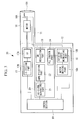
Fig. 1} Fig. 1 is a view showing the overall configuration of a laser ablation device according to a first embodiment of the present invention. - {
Figs. 2A to 2C} Figs. 2A to 2C show an insertion portion of the laser ablation device according to the first embodiment of the present invention:Fig. 2A is a view showing the overall insertion portion;Fig. 2B is a view showing a state in which a shaft and a fiber are fixed; andFig. 2C is a cross-sectional view cut along the line A-A' inFig. 2B . - {
Fig. 3} Fig. 3 is a view showing the overall configuration of a laser ablation device according to a second embodiment of the present invention. - {
Figs. 4A to 4D} Figs. 4A to 4D show an insertion portion of the laser ablation device according to the second embodiment of the present invention:Fig. 4A is a view showing the overall insertion portion;Fig. 4B is a view showing a state in which a shaft and a fiber are fixed;Fig. 4C is a cross-sectional view cut along the line A-A' inFig. 4B; and Fig. 4D is a cross-sectional view cut along the line B-B' inFig. 4B . - {
Figs. 5A and 5B} Figs. 5A and 5B show example laser-light radiation trajectories produced by the fiber of the laser ablation device according to the second embodiment of the present invention. - {
Fig. 6} Fig. 6 is a view showing the overall configuration of a laser ablation device according to a third embodiment of the present invention. - {
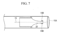
Fig. 7} Fig. 7 is a view showing an insertion portion of the laser ablation device according to the third embodiment of the present invention. - {
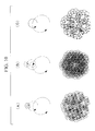
Figs. 8A to 8C} Figs. 8A to 8C show example laser-light radiation trajectories produced by a fiber of the laser ablation device according to the third embodiment of the present invention. - {
Fig. 9} Fig. 9 is a view showing an insertion portion of a laser ablation device according to a modification of the third embodiment of the present invention. - {
Figs. 10A to 10C} Figs. 10A to 10C show example laser-light radiation trajectories produced by a fiber of the laser ablation device according to the modification of the third embodiment of the present invention. - {
Figs. 11A and 11B} Figs. 11A and 11B show other examples of insertion portions of laser ablation devices according to the present invention. - {
Figs. 12A to 12C} Figs. 12A to 12C show example laser-light radiation trajectories produced by fibers of the laser ablation devices shown inFigs. 11A and 11B . - A
laser ablation device 10 according to a first embodiment of the present invention will be described below with reference to the drawings. Thelaser ablation device 10 of this embodiment radiates laser light from an insertion portion, to be described later, onto affected tissue to cauterize the affected tissue, thereby performing treatment for arrhythmia etc., and includes aninsertion portion 11 and amain portion 12. - As shown in
Figs. 1 and2 , theinsertion portion 11 to be inserted into the body of patients is a long bendable pipe conduit and includes afiber 15 that guides laser light emitted from a light source, to be described later, and that radiates the laser light from an insertion-portion distal end and amotor 16 that is provided on thefiber 15 to vibrate thefiber 15 with a predetermined period. Specifically, thefiber 15 is provided integrally with ashaft 16A of themotor 16 and guides laser light while rotating in conjunction with rotation of themotor 16. - Specifically, the
shaft 16A has a hollow structure, and thefiber 15 passes through theshaft 16A. Theshaft 16A of themotor 16 has a bent portion, so that the output of themotor 16 is made to be eccentric with respect to the axis of rotation. As shown inFig. 2A , fourball bearings 16B are disposed in a distal end of theshaft 16A at equal-spaced intervals, thefiber 15 is in contact with theshaft 16A via theball bearings 16B, and thus thefiber 15 is fixed to theshaft 16A. Alens 15A through which laser light emitted from an emitting end of thefiber 15 is transmitted is provided on a distal end surface of theinsertion portion 11. - The
main portion 12 includes alight source section 17, avibration control section 18 that controls the vibration of thefiber 15, and acontrol section 19 that controls thelight source section 17 and thevibration control section 18. - The
light source section 17 includes an LD (laser diode) 17A that serves as the light source, which emits laser light for cauterizing an affected area, and anLD driving part 17B that drives theLD 17A. - The
vibration control section 18 has amotor driving part 18A that rotationally drives themotor 16 and a rotating-speed modulating part 18B that appropriately modulates the rotating speed of themotor 16. - The operation of the thus-configured
laser ablation device 10 will be described below. - The distal end of the
insertion portion 11 of thelaser ablation device 10 is inserted up to the vicinity of an affected area. In this state, when power is supplied from theLD driving part 17B to theLD 17A based on a control signal sent from thecontrol section 19, laser light is emitted from theLD 17A and enters an incident end of thefiber 15 that is located at a base end of theinsertion portion 11. The laser light is guided by thefiber 15 to the distal end of thefiber 15 and is radiated from the emitting end of thefiber 15 onto the affected area via thelens 15A, which is provided at the distal end of theinsertion portion 11. - At this time, the
fiber 15 is provided integrally with theshaft 16A of themotor 16 so as to guide the laser light while rotating in conjunction with rotation of themotor 16. Furthermore, because theshaft 16A of themotor 16 makes the output of themotor 16 eccentric with respect to the axis of rotation, when themotor 16 is rotationally driven by themotor driving part 18A, the laser light emitted from thefiber 15 is radiated onto the affected area while tracing a circular trajectory corresponding to the eccentric position of theshaft 16A. - As described above, according to this embodiment, rotation of the
motor 16 vibrates thefiber 15, which emits laser light, thereby making it also possible to vibrate the laser-light radiation trajectory, thus preventing laser light from being locally radiated onto the affected area and allowing uniform laser-light radiation while expanding the radiation region. - Next, a
laser ablation device 30 according to a second embodiment of the present invention will be described below with reference to the drawings. In this embodiment, identical reference signs are assigned to the same components as those in the above-described first embodiment, and a description thereof will be omitted. This embodiment mainly differs from the first embodiment in thatpiezoelectric elements 15B are provided symmetrically in four directions around the axis of the output end of theshaft 16A, as shown inFig. 3 . - Therefore, the
main portion 12 further includes a piezoelectric-element control section 20 that controls the piezoelectric elements, and thecontrol section 19 controls thelight source section 17, thevibration control section 18, and the piezoelectric-element control section 20. - The piezoelectric-
element control section 20 includes anAM modulation part 23 that supplies electric power to thepiezoelectric elements 15B, aPLL control part 24 that adjusts the phases of modulated signals output from theAM modulation part 23 and the number of rotations of themotor 16, an AC-signal generating part 21 that generates AC signals to be supplied to theAM modulation part 23, and anamplification part 22 that amplifies the AC signals output from the AC-signal generating part 21. - As shown in
Figs. 4A to 4D , thefiber 15 is provided in thehollow shaft 16A, and the distal end of thefiber 15 is fixed to theshaft 16A byball bearings 16B that are provided via anelastic member 16C. Contact points of theball bearings 16B are located at the position of a node of a vibration of the elastic member. Because thepiezoelectric elements 15B are provided symmetrically in four directions around the axis of thefiber 15 via theelastic member 16C and are composed of X-axis-driving piezoelectric elements and Y-axis-driving piezoelectric elements, the phases of the AC signals supplied from the AC-signal generating part 21 to the X-axis-driving piezoelectric elements and the Y-axis-driving piezoelectric elements are shifted by 90 degrees. Furthermore, the modulated signals output from theAM modulation part 23 and the rotating speed of themotor 16 are individually controlled by thePLL control part 24 so as to establish a relationship between frequency division and multiplication. - The operation of the thus-configured laser ablation device will now be described.
- AC signals generated by the AC-
signal generating part 21 are amplified by theamplification part 22 and are AM-modulated at theAM modulation part 23. The frequencies of the voltage and the current to be applied to thepiezoelectric elements 15B are made to match the resonance frequency of a vibration of thefiber 15. When the modulated signals output from theAM modulation part 22 are supplied to thepiezoelectric elements 15B, thepiezoelectric elements 15B vibrate due to the piezoelectric effect, thus vibrating theshaft 16A. The vibration is transferred to make thefiber 15 resonate. - In this state, when the
LD driving part 17B supplies predetermined power to theLD 17A based on a control signal of thecontrol section 19, theLD 17A emits laser light toward the emitting end of thefiber 15. The emitted laser light is radiated onto an affected area from the insertion-portion distal end via thefiber 15. - At this time, as described above, because the
motor 16 is driven, thereby rotating theshaft 16A, and thepiezoelectric elements 15B vibrate due to the piezoelectric effect, thereby vibrating the distal end of theshaft 16A, light radiated from the distal end of theinsertion portion 11 traces a radiation trajectory obtained by superposing a vibration produced by the motor and a vibration produced by thepiezoelectric elements 15B. -
Figs. 5A and 5B show example laser-light radiation trajectories produced by thefiber 15.Fig. 5A shows an example radiation trajectory in the case where, by setting the amplitude of a vibration produced by thepiezoelectric elements 15B smaller than the amplitude of a vibration produced by themotor 16, themotor 16 roughly moves the laser light at the same time as thepiezoelectric elements 15B finely move the laser light.Fig. 5A shows an example laser-light radiation trajectory in the case where thepiezoelectric elements 15B vibrate thefiber 15 in a spiral pattern, andFig. 5B shows an example laser-light radiation trajectory in the case where thepiezoelectric elements 15B vibrate thefiber 15 in a circular trajectory. - In this way, according to this embodiment, by superposing the vibration produced by rotational motion of the
motor 16 and the vibration produced by thepiezoelectric elements 15B, it is possible to prevent the laser light from being locally radiated and also to allow more uniform laser-light radiation, which prevents damage to tissue other than the affected area. Because it is possible to avoid fixed-point radiation and to allow area radiation, the therapeutic dose can be visually perceived with observation optics, such as an endoscope. - Note that the number of rotations, the rotating speed, and the direction of rotation of the motor may be desirably set, and the amplitude of the motor may be different from or may be the same as the amplitude of the piezoelectric elements. Furthermore, in this embodiment, although a description has been given of a case in which the frequencies of the voltage and the current to be applied to the
piezoelectric elements 15B are made to match the resonance frequency of the vibration of thefiber 15, the frequencies are not necessarily resonant and may be non-resonant. - Next, a
laser ablation device 40 according to a third embodiment of the present invention will be described with reference to the drawings. In this embodiment, identical reference signs are assigned to the same components as those in the above-described second embodiment, and a description thereof will be omitted. This embodiment mainly differs from the second embodiment in thatpiezoelectric elements 15C are provided instead of themotor 16, as shown inFigs. 6 and7 . - Specifically, the
fiber 15 is provided with anelastic member 32 for supporting thepiezoelectric elements 15B and thepiezoelectric elements 15C. Thepiezoelectric elements 15B are provided symmetrically in four directions at a distal end of theelastic member 32, and thepiezoelectric elements 15C are provided symmetrically in four directions at a base end thereof. - Therefore, the
main portion 12 includes, instead of the piezoelectric-element control section 20, a piezoelectric-element control section 28 that controls thepiezoelectric elements 15B and thepiezoelectric elements 15C. - The piezoelectric-
element control section 28 includesAM modulation parts piezoelectric elements PLL control part 24 that individually adjusts the phases of modulated signals output from theAM modulation parts signal generating parts 21B and 21C that generate AC signals to be supplied to theAM modulation parts amplification parts signal generating parts 21B and 21C. - AC signals generated by the AC-
signal generating part 21B are amplified at theamplification part 22B and are AM-modulated at theAM modulation part 23B. Similarly, AC signals generated by the AC-signal generating part 21C are amplified at theamplification part 22C and are AM-modulated at theAM modulation part 23C. Although the modulated signals output from theAM modulation part 23B and theAM modulation part 23C have different frequencies, they are controlled at thePLL control part 24 so as to establish a relationship between frequency division and multiplication. Furthermore, the frequencies of the voltage and the current to be applied to thepiezoelectric elements 15B are made to match the resonance frequency at the distal end portion of theelastic member 32, and the frequencies of the voltage and the current to be applied to thepiezoelectric elements 15C are made to match the resonance frequency of thefiber 15. - The operation of the thus-configured laser ablation device will now be described. Modulated signals output from the
AM modulation part 23B and theAM modulation part 23C are supplied to thepiezoelectric elements piezoelectric elements elastic member 32 to vibrate thefiber 15. - In this state, when the
LD driving part 17B supplies predetermined power to theLD 17A based on a control signal output from thecontrol section 19, theLD 17A emits laser light toward the incident end of thefiber 15. The emitted laser light is emitted from the distal end of theinsertion portion 11 via thefiber 15. - At this time, because the
piezoelectric elements fiber 15, the laser light emitted from the distal end of theinsertion portion 11 traces a radiation trajectory obtained by superposing a vibration produced by thepiezoelectric elements 15B and a vibration produced by thepiezoelectric elements 15C. -
Figs. 8A to 8C show example laser-light radiation trajectories produced by thefiber 15.Figs. 8A to 8C show example radiation trajectories in the case where, by setting the amplitude of a vibration produced by thepiezoelectric elements 15B smaller than the amplitude of a vibration produced by thepiezoelectric elements 15C, thepiezoelectric elements 15C roughly move the laser light at the same time as thepiezoelectric elements 15B finely move the laser light.Fig. 8A shows an example laser-light radiation trajectory in the case where thepiezoelectric elements 15B vibrate thefiber 15 in a spiral pattern at the same time as thepiezoelectric elements 15C vibrate thefiber 15 in a circular trajectory, andFig. 8B shows an example laser-light radiation trajectory in the case where thepiezoelectric elements 15B vibrate thefiber 15 in the same way as inFig. 8A , and thepiezoelectric elements 15C vibrate thefiber 15 in a spiral pattern.Fig. 8C shows an example laser-light radiation trajectory in the case where both thepiezoelectric elements fiber 15 in a circular trajectory. - In this way, according to this embodiment, the vibration produced by the
piezoelectric elements 15B and the vibration produced by thepiezoelectric elements 15C are transferred to thefiber 15 via theelastic member 32, and the vibration produced by thepiezoelectric elements 15B and the vibration produced by thepiezoelectric elements 15C are superposed, thereby making it possible to prevent the laser light from being locally radiated and also to allow more uniform laser-light radiation, which prevents damage to tissue other than the affected area. Because it is possible to avoid fixed-point radiation and to allow area radiation, the therapeutic dose can be visually perceived with observation optics, such as an endoscope. Because the variable range of the radiation region is wide, it is possible to respond flexibly to different treatment regions. - Next, a laser ablation device according to a modification of the third embodiment of the present invention will be described with reference to the drawings. In this modification, identical reference signs are assigned to the same components as those in the above-described third embodiment, and a description thereof will be omitted. This embodiment mainly differs from the third embodiment in that a so-called three-stage structure in which piezoelectric elements are provided at three places in the axial direction of the
elastic member 32 is built, as shown inFig. 9 . - Specifically, the
fiber 15 is provided with anelastic member 32 for supporting thepiezoelectric elements 15B, thepiezoelectric elements 15C, andpiezoelectric elements 15D. Theelastic member 32 has thepiezoelectric elements 15B provided symmetrically in four directions at the distal end, thepiezoelectric elements 15C provided symmetrically in four directions closer to the base end than thepiezoelectric elements 15B, and thepiezoelectric elements 15D provided symmetrically in four directions at the base end. - Therefore, as in the above-described third embodiment, the main portion includes, instead of the piezoelectric-
element control section 20, a piezoelectric-element control section 28 that controls thepiezoelectric elements 15B, thepiezoelectric elements 15C, and thepiezoelectric elements 15D, and the piezoelectric-element control section 28 includes AM modulation parts that supply electric power to thepiezoelectric elements -
Figs. 10A to 10C show example laser-light radiation trajectories produced by thefiber 15 in the case where thepiezoelectric elements Figs. 10A to 10C show example radiation trajectories in the case where, by setting the amplitude of a vibration produced by the piezoelectric elements that are provided closer to the distal end of thefiber 15 to be smaller, the piezoelectric elements that are provided closer to the base end roughly move the laser light at the same time as the piezoelectric elements that are provided closer to the distal end finely move the laser light. In particular,Fig. 10A shows an example laser-light radiation trajectory in the case where thepiezoelectric elements 15B vibrate thefiber 15 in a spiral pattern at the same time as thepiezoelectric elements fiber 15 in a circular trajectory.Fig. 10B shows an example laser-light radiation trajectory in the case where thepiezoelectric elements 15D vibrate thefiber 15 in a circular trajectory at the same time as thepiezoelectric elements fiber 15 in a spiral pattern.Fig. 10C shows an example laser-light radiation trajectory in the case where all of thepiezoelectric elements fiber 15 in a circular trajectory. - In this way, according to this embodiment, the vibrations produced by the
piezoelectric elements fiber 15 via theelastic member 32, and the vibrations produced by thepiezoelectric elements - Note that, in the above-described embodiments, although piezoelectric elements are used as a means for producing a vibration, such means is not necessarily limited to the piezoelectric elements and can be electromagnetic vibration elements, for example.
- Furthermore, although the third embodiment is provided with a two-stage structure that has a drive unit in which the
piezoelectric elements 15B produce a vibration and a drive unit in which thepiezoelectric elements 15C produce a vibration, and the modification of the third embodiment is provided with a three-stage structure that has three drive units in each of which the piezoelectric elements produce a vibration, a structure having four or more stages may be provided, and every possible means that can vibrate the fiber, such as motors, piezoelectric elements, and electromagnetic vibration elements, can be used alone or in appropriate combinations, as drive units. - For example, as shown in
Figs. 11A and 11B , an electromagnetic vibration element 35 has apermanent magnet 33 that is disposed on the axis of theelastic member 32, which transfers a vibration to thefiber 15, and acoil 34 that is provided so as to surround thepermanent magnet 33. When the thus-configured electromagnetic vibration element 35 is used, it is possible to build a structure in which the electromagnetic vibration element 35 is provided closer to the base end of thefiber 15, and thepiezoelectric elements 15C are provided closer to the distal end thereof, as shown inFig. 11A , or a structure in which the electromagnetic vibration element 35 is provided closer to the base end of thefiber 15 and also closer to the distal end thereof, as shown inFig. 11B . - Then, when current is supplied to the coil, the permanent magnet vibrates due to electromagnetic induction, and this vibration vibrates the distal end of the
fiber 15 via the elastic member. Because the electromagnetic vibration element 35 can perform raster scanning, when the piezoelectric elements are provided closer to the distal end of thefiber 15, as shown inFig. 11A , the raster scanning can be combined with a vibration produced by rotation of the piezoelectric elements, as shown inFigs. 12A and 12B . Furthermore, when the electromagnetic vibration element 35 is provided closer to the base end of thefiber 15 and also closer to the distal end thereof, as shown inFig. 11B , if both of the electromagnetic vibration elements 35 perform raster scanning, a scan trajectory shown inFig. 12C can be obtained. In either case, laser light can be prevented from being locally radiated. -
- 10, 30, 40 laser ablation device
- 11 insertion portion
- 15 fiber
- 15B piezoelectric elements
- 15C piezoelectric elements
- 16 motor
- 16A shaft
- 17A light source
- 18 vibration control section
- 19 control section
- 20, 28 piezoelectric-element control section
Claims (10)
- A laser ablation device comprising:a light source that emits laser light for cauterizing an affected area;a fiber that is provided in an insertion portion and that guides the laser light emitted from the light source to radiate the laser light from an insertion-portion distal end; anda first drive unit that is provided on the fiber and that vibrates the fiber with a first period.
- A laser ablation device according to claim 1, further comprising a second drive unit that vibrates the fiber with a second period.
- A laser ablation device according to claim 2, wherein the amplitude produced by the second drive unit is larger than the amplitude produced by the first drive unit.
- A laser ablation device according to claim 2 or 3,
wherein the first drive unit is provided closer to a distal end of the fiber than the second drive unit; and
the second period is longer than the first period. - A laser ablation device according to one of claims 2 to 4,
wherein the first drive unit is provided closer to a distal end of the fiber than the second drive unit; and
the second period is a period n times (n is an integer) the first period. - A laser ablation device according to one of claims 2 to 5,
wherein the fiber is made to perform rotational motions by the first drive unit and the second drive unit; and
the number of rotations of the fiber due to the first drive unit is faster than the number of rotations of the fiber due to the second drive unit. - A laser ablation device according to one of claims 1 to 6, wherein the fiber is made to perform a resonant motion.
- A laser ablation device according to one of claims 1 to 5, wherein the fiber is made to perform raster scanning.
- A laser ablation device according to one of claims 1 to 5, wherein the fiber is made to perform spiral scanning.
- A laser ablation device according to one of claims 1 to 9, further comprising one or more drive units that vibrate the fiber periodically.
Applications Claiming Priority (2)
| Application Number | Priority Date | Filing Date | Title |
|---|---|---|---|
| JP2012249519A JP6086704B2 (en) | 2012-11-13 | 2012-11-13 | Laser ablation equipment |
| PCT/JP2013/074632 WO2014077022A1 (en) | 2012-11-13 | 2013-09-12 | Laser ablation device |
Publications (3)
| Publication Number | Publication Date |
|---|---|
| EP2921126A1 true EP2921126A1 (en) | 2015-09-23 |
| EP2921126A4 EP2921126A4 (en) | 2016-07-06 |
| EP2921126B1 EP2921126B1 (en) | 2017-11-01 |
Family
ID=50730945
Family Applications (1)
| Application Number | Title | Priority Date | Filing Date |
|---|---|---|---|
| EP13855396.1A Not-in-force EP2921126B1 (en) | 2012-11-13 | 2013-09-12 | Laser ablation device |
Country Status (5)
| Country | Link |
|---|---|
| US (1) | US20150257832A1 (en) |
| EP (1) | EP2921126B1 (en) |
| JP (1) | JP6086704B2 (en) |
| CN (1) | CN104780860B (en) |
| WO (1) | WO2014077022A1 (en) |
Families Citing this family (5)
| Publication number | Priority date | Publication date | Assignee | Title |
|---|---|---|---|---|
| US20160059292A1 (en) * | 2014-08-27 | 2016-03-03 | Namiki Precision Jewel Co., Ltd. | Bending device |
| CN110536628B (en) * | 2017-04-04 | 2022-05-24 | 奇跃公司 | Deformation mode actuation for fiber optic scanner for increased field of view |
| US12279812B2 (en) | 2019-08-05 | 2025-04-22 | Gyrus Acmi, Inc. | Laser fiber varying lateral position and intensity |
| JP7479448B2 (en) * | 2019-08-05 | 2024-05-08 | ジャイラス エーシーエムアイ インク ディー/ビー/エー オリンパス サージカル テクノロジーズ アメリカ | Laser fiber with variable lateral position and intensity |
| WO2022190259A1 (en) * | 2021-03-10 | 2022-09-15 | オリンパス株式会社 | Laser scanning method, laser irradiation device, and laser treatment system |
Family Cites Families (23)
| Publication number | Priority date | Publication date | Assignee | Title |
|---|---|---|---|---|
| US5207669A (en) * | 1989-05-26 | 1993-05-04 | C. R. Bard, Inc. | Optical fiber diffusion tip for uniform illumination |
| US6485413B1 (en) * | 1991-04-29 | 2002-11-26 | The General Hospital Corporation | Methods and apparatus for forward-directed optical scanning instruments |
| JPH078502A (en) | 1993-06-29 | 1995-01-13 | Nec San-Ei Instr Co Ltd | Laser ablation catheter |
| US5733277A (en) * | 1994-06-22 | 1998-03-31 | Pallarito; Allan L. | Optical fibre and laser for removal of arterial or vascular obstructions |
| JP2001190565A (en) * | 2000-01-06 | 2001-07-17 | Slt Japan:Kk | Laser beam irradiation system to living body |
| US6856712B2 (en) * | 2000-11-27 | 2005-02-15 | University Of Washington | Micro-fabricated optical waveguide for use in scanning fiber displays and scanned fiber image acquisition |
| JP4537630B2 (en) * | 2001-09-10 | 2010-09-01 | ヤーマン株式会社 | Laser treatment equipment |
| JP2003265498A (en) * | 2002-03-14 | 2003-09-24 | Intorasu Ltd | Laser irradiation system for living tissue |
| US7150517B2 (en) * | 2003-03-28 | 2006-12-19 | Kyocera Corporation | Method for driving piezoelectric ink jet head |
| US20040231682A1 (en) * | 2003-05-20 | 2004-11-25 | Richard Stoltz | Scanned small spot ablation with a high-rep-rate |
| US8308717B2 (en) * | 2004-06-21 | 2012-11-13 | Seilex Ltd | Thermal energy applicator |
| US7333698B2 (en) * | 2004-08-05 | 2008-02-19 | Polyoptics Ltd | Optical scanning device |
| WO2006072186A1 (en) * | 2005-01-06 | 2006-07-13 | Thyssenkrupp Presta Ag | Device for superimposing rotational speeds, comprising a servodrive |
| KR20090034925A (en) * | 2006-06-27 | 2009-04-08 | 팔로마 메디칼 테크놀로지스, 인코포레이티드 | Handheld tailings device |
| CN101505675A (en) * | 2006-06-27 | 2009-08-12 | 帕洛玛医疗技术公司 | Handheld photocosmetic device |
| US20080306473A1 (en) * | 2006-12-07 | 2008-12-11 | Georg Schuele | Tissue-treating device with medium-control mechanism |
| US7496259B2 (en) * | 2007-01-02 | 2009-02-24 | University Of Washington | Endoscope with optical fiber and fiber optics system |
| US9693826B2 (en) * | 2008-02-28 | 2017-07-04 | Biolitec Unternehmensbeteiligungs Ii Ag | Endoluminal laser ablation device and method for treating veins |
| JP2010268961A (en) * | 2009-05-21 | 2010-12-02 | Hoya Corp | Medical observation system |
| DE102009029055A1 (en) * | 2009-09-01 | 2011-03-10 | Robert Bosch Gmbh | Drilling and / or chiselling device |
| WO2011085299A2 (en) * | 2010-01-08 | 2011-07-14 | Ceramoptec Industries, Inc. | Device and method for underskin radiation treatment of adipose tissue |
| EP2561395A2 (en) * | 2010-04-21 | 2013-02-27 | Applied Precision, Inc. | Uniform light source for an imaging instrument |
| EP2412341B1 (en) * | 2010-07-29 | 2015-05-20 | SIE AG, Surgical Instrument Engineering | Device for machining eye tissue using femtosecond laser pulses |
-
2012
- 2012-11-13 JP JP2012249519A patent/JP6086704B2/en not_active Expired - Fee Related
-
2013
- 2013-09-12 EP EP13855396.1A patent/EP2921126B1/en not_active Not-in-force
- 2013-09-12 CN CN201380058013.8A patent/CN104780860B/en not_active Expired - Fee Related
- 2013-09-12 WO PCT/JP2013/074632 patent/WO2014077022A1/en not_active Ceased
-
2015
- 2015-04-15 US US14/687,100 patent/US20150257832A1/en not_active Abandoned
Also Published As
| Publication number | Publication date |
|---|---|
| CN104780860A (en) | 2015-07-15 |
| JP2014097123A (en) | 2014-05-29 |
| US20150257832A1 (en) | 2015-09-17 |
| CN104780860B (en) | 2017-10-17 |
| JP6086704B2 (en) | 2017-03-01 |
| EP2921126B1 (en) | 2017-11-01 |
| WO2014077022A1 (en) | 2014-05-22 |
| EP2921126A4 (en) | 2016-07-06 |
Similar Documents
| Publication | Publication Date | Title |
|---|---|---|
| EP2921126A1 (en) | Laser ablation device | |
| JP7591070B2 (en) | System and method for driving an ultrasonic handpiece using a linear amplifier - Patents.com | |
| CN101517883B (en) | Ultrasonic manipulation device and microtube inspection system | |
| EP2421447B1 (en) | Improved bone resector | |
| JP6086741B2 (en) | Scanning observation apparatus and operation method thereof | |
| JP2016511075A (en) | Mechanically heated catheter | |
| CN103561624A (en) | Light irradiation device, scanning endoscopic apparatus, light irradiation device manufacturing method, and scanning endoscope manufacturing method | |
| CN103815947A (en) | Fluid-surgical instrument with variable spray image | |
| US20150066032A1 (en) | Bone resector | |
| EP3092939A1 (en) | Optical scanning device and scanning-type endoscope | |
| JP5690452B2 (en) | Ultrasonic transmission unit and ultrasonic treatment apparatus | |
| JP2015058234A (en) | Medical liquid injection device | |
| JP6393382B2 (en) | Medical equipment | |
| US10939935B2 (en) | Ultrasonic treatment instrument for articulations, and ultrasonic treatment system for articulations | |
| WO2014126558A1 (en) | Enclosed laser medical device/system | |
| JP6280633B2 (en) | Friction drive actuator | |
| JP2014151083A (en) | Ultrasonic treatment instrument | |
| KR101179015B1 (en) | Medical instrument using laser and hand piece used in the medical instrument | |
| KR101418718B1 (en) | Structure of instrument coupler of surgical robot arm | |
| US20260077212A1 (en) | Optical fiber retainer, phototherapy device, and phototherapy system | |
| JP2014161491A (en) | Laser treatment device and control method of laser treatment device | |
| US12127806B1 (en) | Computer-assisted surgical robotic ablation | |
| JPH1033546A (en) | Tracheal device | |
| JP6419363B1 (en) | Treatment device | |
| KR20240149470A (en) | Apparartus of apoptosis using electric field |
Legal Events
| Date | Code | Title | Description |
|---|---|---|---|
| PUAI | Public reference made under article 153(3) epc to a published international application that has entered the european phase |
Free format text: ORIGINAL CODE: 0009012 |
|
| 17P | Request for examination filed |
Effective date: 20150528 |
|
| AK | Designated contracting states |
Kind code of ref document: A1 Designated state(s): AL AT BE BG CH CY CZ DE DK EE ES FI FR GB GR HR HU IE IS IT LI LT LU LV MC MK MT NL NO PL PT RO RS SE SI SK SM TR |
|
| AX | Request for extension of the european patent |
Extension state: BA ME |
|
| DAX | Request for extension of the european patent (deleted) | ||
| RA4 | Supplementary search report drawn up and despatched (corrected) |
Effective date: 20160608 |
|
| RIC1 | Information provided on ipc code assigned before grant |
Ipc: A61B 18/20 20060101AFI20160602BHEP |
|
| RAP1 | Party data changed (applicant data changed or rights of an application transferred) |
Owner name: OLYMPUS CORPORATION |
|
| RIN1 | Information on inventor provided before grant (corrected) |
Inventor name: EBATA, SADAO |
|
| GRAP | Despatch of communication of intention to grant a patent |
Free format text: ORIGINAL CODE: EPIDOSNIGR1 |
|
| STAA | Information on the status of an ep patent application or granted ep patent |
Free format text: STATUS: GRANT OF PATENT IS INTENDED |
|
| INTG | Intention to grant announced |
Effective date: 20170526 |
|
| RIN1 | Information on inventor provided before grant (corrected) |
Inventor name: EBATA, SADAO |
|
| GRAS | Grant fee paid |
Free format text: ORIGINAL CODE: EPIDOSNIGR3 |
|
| GRAA | (expected) grant |
Free format text: ORIGINAL CODE: 0009210 |
|
| STAA | Information on the status of an ep patent application or granted ep patent |
Free format text: STATUS: THE PATENT HAS BEEN GRANTED |
|
| AK | Designated contracting states |
Kind code of ref document: B1 Designated state(s): AL AT BE BG CH CY CZ DE DK EE ES FI FR GB GR HR HU IE IS IT LI LT LU LV MC MK MT NL NO PL PT RO RS SE SI SK SM TR |
|
| REG | Reference to a national code |
Ref country code: GB Ref legal event code: FG4D |
|
| REG | Reference to a national code |
Ref country code: CH Ref legal event code: EP Ref country code: AT Ref legal event code: REF Ref document number: 941218 Country of ref document: AT Kind code of ref document: T Effective date: 20171115 |
|
| REG | Reference to a national code |
Ref country code: IE Ref legal event code: FG4D |
|
| REG | Reference to a national code |
Ref country code: DE Ref legal event code: R096 Ref document number: 602013028929 Country of ref document: DE |
|
| REG | Reference to a national code |
Ref country code: NL Ref legal event code: MP Effective date: 20171101 |
|
| REG | Reference to a national code |
Ref country code: LT Ref legal event code: MG4D |
|
| REG | Reference to a national code |
Ref country code: AT Ref legal event code: MK05 Ref document number: 941218 Country of ref document: AT Kind code of ref document: T Effective date: 20171101 |
|
| PG25 | Lapsed in a contracting state [announced via postgrant information from national office to epo] |
Ref country code: ES Free format text: LAPSE BECAUSE OF FAILURE TO SUBMIT A TRANSLATION OF THE DESCRIPTION OR TO PAY THE FEE WITHIN THE PRESCRIBED TIME-LIMIT Effective date: 20171101 Ref country code: SE Free format text: LAPSE BECAUSE OF FAILURE TO SUBMIT A TRANSLATION OF THE DESCRIPTION OR TO PAY THE FEE WITHIN THE PRESCRIBED TIME-LIMIT Effective date: 20171101 Ref country code: NL Free format text: LAPSE BECAUSE OF FAILURE TO SUBMIT A TRANSLATION OF THE DESCRIPTION OR TO PAY THE FEE WITHIN THE PRESCRIBED TIME-LIMIT Effective date: 20171101 Ref country code: FI Free format text: LAPSE BECAUSE OF FAILURE TO SUBMIT A TRANSLATION OF THE DESCRIPTION OR TO PAY THE FEE WITHIN THE PRESCRIBED TIME-LIMIT Effective date: 20171101 Ref country code: LT Free format text: LAPSE BECAUSE OF FAILURE TO SUBMIT A TRANSLATION OF THE DESCRIPTION OR TO PAY THE FEE WITHIN THE PRESCRIBED TIME-LIMIT Effective date: 20171101 Ref country code: NO Free format text: LAPSE BECAUSE OF FAILURE TO SUBMIT A TRANSLATION OF THE DESCRIPTION OR TO PAY THE FEE WITHIN THE PRESCRIBED TIME-LIMIT Effective date: 20180201 |
|
| PG25 | Lapsed in a contracting state [announced via postgrant information from national office to epo] |
Ref country code: RS Free format text: LAPSE BECAUSE OF FAILURE TO SUBMIT A TRANSLATION OF THE DESCRIPTION OR TO PAY THE FEE WITHIN THE PRESCRIBED TIME-LIMIT Effective date: 20171101 Ref country code: BG Free format text: LAPSE BECAUSE OF FAILURE TO SUBMIT A TRANSLATION OF THE DESCRIPTION OR TO PAY THE FEE WITHIN THE PRESCRIBED TIME-LIMIT Effective date: 20180201 Ref country code: LV Free format text: LAPSE BECAUSE OF FAILURE TO SUBMIT A TRANSLATION OF THE DESCRIPTION OR TO PAY THE FEE WITHIN THE PRESCRIBED TIME-LIMIT Effective date: 20171101 Ref country code: HR Free format text: LAPSE BECAUSE OF FAILURE TO SUBMIT A TRANSLATION OF THE DESCRIPTION OR TO PAY THE FEE WITHIN THE PRESCRIBED TIME-LIMIT Effective date: 20171101 Ref country code: AT Free format text: LAPSE BECAUSE OF FAILURE TO SUBMIT A TRANSLATION OF THE DESCRIPTION OR TO PAY THE FEE WITHIN THE PRESCRIBED TIME-LIMIT Effective date: 20171101 Ref country code: IS Free format text: LAPSE BECAUSE OF FAILURE TO SUBMIT A TRANSLATION OF THE DESCRIPTION OR TO PAY THE FEE WITHIN THE PRESCRIBED TIME-LIMIT Effective date: 20180301 Ref country code: GR Free format text: LAPSE BECAUSE OF FAILURE TO SUBMIT A TRANSLATION OF THE DESCRIPTION OR TO PAY THE FEE WITHIN THE PRESCRIBED TIME-LIMIT Effective date: 20180202 |
|
| PG25 | Lapsed in a contracting state [announced via postgrant information from national office to epo] |
Ref country code: CZ Free format text: LAPSE BECAUSE OF FAILURE TO SUBMIT A TRANSLATION OF THE DESCRIPTION OR TO PAY THE FEE WITHIN THE PRESCRIBED TIME-LIMIT Effective date: 20171101 Ref country code: CY Free format text: LAPSE BECAUSE OF FAILURE TO SUBMIT A TRANSLATION OF THE DESCRIPTION OR TO PAY THE FEE WITHIN THE PRESCRIBED TIME-LIMIT Effective date: 20171101 Ref country code: EE Free format text: LAPSE BECAUSE OF FAILURE TO SUBMIT A TRANSLATION OF THE DESCRIPTION OR TO PAY THE FEE WITHIN THE PRESCRIBED TIME-LIMIT Effective date: 20171101 Ref country code: DK Free format text: LAPSE BECAUSE OF FAILURE TO SUBMIT A TRANSLATION OF THE DESCRIPTION OR TO PAY THE FEE WITHIN THE PRESCRIBED TIME-LIMIT Effective date: 20171101 Ref country code: SK Free format text: LAPSE BECAUSE OF FAILURE TO SUBMIT A TRANSLATION OF THE DESCRIPTION OR TO PAY THE FEE WITHIN THE PRESCRIBED TIME-LIMIT Effective date: 20171101 |
|
| REG | Reference to a national code |
Ref country code: DE Ref legal event code: R097 Ref document number: 602013028929 Country of ref document: DE |
|
| PG25 | Lapsed in a contracting state [announced via postgrant information from national office to epo] |
Ref country code: IT Free format text: LAPSE BECAUSE OF FAILURE TO SUBMIT A TRANSLATION OF THE DESCRIPTION OR TO PAY THE FEE WITHIN THE PRESCRIBED TIME-LIMIT Effective date: 20171101 Ref country code: RO Free format text: LAPSE BECAUSE OF FAILURE TO SUBMIT A TRANSLATION OF THE DESCRIPTION OR TO PAY THE FEE WITHIN THE PRESCRIBED TIME-LIMIT Effective date: 20171101 Ref country code: PL Free format text: LAPSE BECAUSE OF FAILURE TO SUBMIT A TRANSLATION OF THE DESCRIPTION OR TO PAY THE FEE WITHIN THE PRESCRIBED TIME-LIMIT Effective date: 20171101 Ref country code: SM Free format text: LAPSE BECAUSE OF FAILURE TO SUBMIT A TRANSLATION OF THE DESCRIPTION OR TO PAY THE FEE WITHIN THE PRESCRIBED TIME-LIMIT Effective date: 20171101 |
|
| PLBE | No opposition filed within time limit |
Free format text: ORIGINAL CODE: 0009261 |
|
| STAA | Information on the status of an ep patent application or granted ep patent |
Free format text: STATUS: NO OPPOSITION FILED WITHIN TIME LIMIT |
|
| 26N | No opposition filed |
Effective date: 20180802 |
|
| PG25 | Lapsed in a contracting state [announced via postgrant information from national office to epo] |
Ref country code: SI Free format text: LAPSE BECAUSE OF FAILURE TO SUBMIT A TRANSLATION OF THE DESCRIPTION OR TO PAY THE FEE WITHIN THE PRESCRIBED TIME-LIMIT Effective date: 20171101 |
|
| PGFP | Annual fee paid to national office [announced via postgrant information from national office to epo] |
Ref country code: DE Payment date: 20180927 Year of fee payment: 6 |
|
| PG25 | Lapsed in a contracting state [announced via postgrant information from national office to epo] |
Ref country code: MC Free format text: LAPSE BECAUSE OF FAILURE TO SUBMIT A TRANSLATION OF THE DESCRIPTION OR TO PAY THE FEE WITHIN THE PRESCRIBED TIME-LIMIT Effective date: 20171101 |
|
| REG | Reference to a national code |
Ref country code: CH Ref legal event code: PL |
|
| GBPC | Gb: european patent ceased through non-payment of renewal fee |
Effective date: 20180912 |
|
| REG | Reference to a national code |
Ref country code: BE Ref legal event code: MM Effective date: 20180930 |
|
| REG | Reference to a national code |
Ref country code: IE Ref legal event code: MM4A |
|
| PG25 | Lapsed in a contracting state [announced via postgrant information from national office to epo] |
Ref country code: LU Free format text: LAPSE BECAUSE OF NON-PAYMENT OF DUE FEES Effective date: 20180912 |
|
| PG25 | Lapsed in a contracting state [announced via postgrant information from national office to epo] |
Ref country code: IE Free format text: LAPSE BECAUSE OF NON-PAYMENT OF DUE FEES Effective date: 20180912 |
|
| PG25 | Lapsed in a contracting state [announced via postgrant information from national office to epo] |
Ref country code: FR Free format text: LAPSE BECAUSE OF NON-PAYMENT OF DUE FEES Effective date: 20180930 Ref country code: BE Free format text: LAPSE BECAUSE OF NON-PAYMENT OF DUE FEES Effective date: 20180930 Ref country code: LI Free format text: LAPSE BECAUSE OF NON-PAYMENT OF DUE FEES Effective date: 20180930 Ref country code: CH Free format text: LAPSE BECAUSE OF NON-PAYMENT OF DUE FEES Effective date: 20180930 |
|
| PG25 | Lapsed in a contracting state [announced via postgrant information from national office to epo] |
Ref country code: GB Free format text: LAPSE BECAUSE OF NON-PAYMENT OF DUE FEES Effective date: 20180912 |
|
| PG25 | Lapsed in a contracting state [announced via postgrant information from national office to epo] |
Ref country code: MT Free format text: LAPSE BECAUSE OF NON-PAYMENT OF DUE FEES Effective date: 20180912 |
|
| PG25 | Lapsed in a contracting state [announced via postgrant information from national office to epo] |
Ref country code: TR Free format text: LAPSE BECAUSE OF FAILURE TO SUBMIT A TRANSLATION OF THE DESCRIPTION OR TO PAY THE FEE WITHIN THE PRESCRIBED TIME-LIMIT Effective date: 20171101 |
|
| REG | Reference to a national code |
Ref country code: DE Ref legal event code: R119 Ref document number: 602013028929 Country of ref document: DE |
|
| PG25 | Lapsed in a contracting state [announced via postgrant information from national office to epo] |
Ref country code: PT Free format text: LAPSE BECAUSE OF FAILURE TO SUBMIT A TRANSLATION OF THE DESCRIPTION OR TO PAY THE FEE WITHIN THE PRESCRIBED TIME-LIMIT Effective date: 20171101 |
|
| PG25 | Lapsed in a contracting state [announced via postgrant information from national office to epo] |
Ref country code: HU Free format text: LAPSE BECAUSE OF FAILURE TO SUBMIT A TRANSLATION OF THE DESCRIPTION OR TO PAY THE FEE WITHIN THE PRESCRIBED TIME-LIMIT; INVALID AB INITIO Effective date: 20130912 Ref country code: MK Free format text: LAPSE BECAUSE OF NON-PAYMENT OF DUE FEES Effective date: 20171101 |
|
| PG25 | Lapsed in a contracting state [announced via postgrant information from national office to epo] |
Ref country code: DE Free format text: LAPSE BECAUSE OF NON-PAYMENT OF DUE FEES Effective date: 20200401 Ref country code: AL Free format text: LAPSE BECAUSE OF FAILURE TO SUBMIT A TRANSLATION OF THE DESCRIPTION OR TO PAY THE FEE WITHIN THE PRESCRIBED TIME-LIMIT Effective date: 20171101 |