EP2921079B1 - Furniture for sitting or lying on with connection part - Google Patents
Furniture for sitting or lying on with connection part Download PDFInfo
- Publication number
- EP2921079B1 EP2921079B1 EP15155573.7A EP15155573A EP2921079B1 EP 2921079 B1 EP2921079 B1 EP 2921079B1 EP 15155573 A EP15155573 A EP 15155573A EP 2921079 B1 EP2921079 B1 EP 2921079B1
- Authority
- EP
- European Patent Office
- Prior art keywords
- connection
- seating
- frame
- attachment
- reclining furniture
- Prior art date
- Legal status (The legal status is an assumption and is not a legal conclusion. Google has not performed a legal analysis and makes no representation as to the accuracy of the status listed.)
- Active
Links
- 229920003023 plastic Polymers 0.000 claims description 5
- 239000004033 plastic Substances 0.000 claims description 5
- 239000002184 metal Substances 0.000 claims description 2
- 230000000903 blocking effect Effects 0.000 claims 1
- 239000000463 material Substances 0.000 claims 1
- 238000003780 insertion Methods 0.000 description 7
- 230000037431 insertion Effects 0.000 description 7
- 238000009434 installation Methods 0.000 description 3
- 238000004519 manufacturing process Methods 0.000 description 3
- 229910000831 Steel Inorganic materials 0.000 description 2
- 239000010959 steel Substances 0.000 description 2
- 150000001875 compounds Chemical class 0.000 description 1
- 238000006073 displacement reaction Methods 0.000 description 1
- 230000000694 effects Effects 0.000 description 1
- 230000005484 gravity Effects 0.000 description 1
- 230000002093 peripheral effect Effects 0.000 description 1
Images


Classifications
-
- A—HUMAN NECESSITIES
- A47—FURNITURE; DOMESTIC ARTICLES OR APPLIANCES; COFFEE MILLS; SPICE MILLS; SUCTION CLEANERS IN GENERAL
- A47C—CHAIRS; SOFAS; BEDS
- A47C7/00—Parts, details, or accessories of chairs or stools
- A47C7/54—Supports for the arms
- A47C7/546—Supports for the arms of detachable type
-
- A—HUMAN NECESSITIES
- A47—FURNITURE; DOMESTIC ARTICLES OR APPLIANCES; COFFEE MILLS; SPICE MILLS; SUCTION CLEANERS IN GENERAL
- A47C—CHAIRS; SOFAS; BEDS
- A47C7/00—Parts, details, or accessories of chairs or stools
- A47C7/36—Supports for the head or the back
- A47C7/40—Supports for the head or the back for the back
- A47C7/42—Supports for the head or the back for the back of detachable or loose type
Definitions
- the invention relates to a seat and / or reclining furniture, in particular armchair, sofa, couch or bed, with a frame and at least one attachment, wherein the attachment is connected via at least one mounting unit comprising at least two separate connections to the frame, wherein the first connection is a plug connection, wherein the attachment is held pivotally in the inserted state relative to the frame.
- Seating furniture and reclining furniture are usually made from a number of prefabricated components to reduce manufacturing costs.
- the seating and reclining furniture typically have a structuring and contributing to the strength of the frame on which other components, so-called attachments are mounted.
- As a frame both very simply designed frame and functional fittings and swivel fittings come into question when the seating or reclining furniture between different positions is adjustable to offer the user of the chair several comfortable positions.
- the seating or the reclining furniture can be a chair, a sofa, a couch or a bed.
- attachments are, for example, a backrest, a seat, a footboard, an armrest or a side panel in question.
- Each of these attachments can be made adjustable if necessary, either separately or together with at least one additional attachment.
- a chair of the type mentioned is from the DE 44 40 553 C1 known. Another seating is for example from the DE 101 17 820 A1 known.
- the backrest can be plugged in the assembly of the chair in a frame.
- two backs are made on each side of the backrest separate connections between the backrest and the frame closed.
- the frame on each side of the backrest has two slots in the roles of the backrest can be introduced. The roles are introduced one after the other. First, a roller is inserted into a corresponding slot on each side and the backrest then pivoted so far, until the other two rollers get into engagement with the remaining slots.
- the first connection between the attachment and the frame is first produced during assembly of the chair and / or reclining furniture.
- This connection is also a plug connection.
- Such a connection can be produced easily, quickly and inexpensively. It is preferred if a section of the attachment provided for this purpose is inserted into a section of the frame designed for this, in order to simplify the mounting of the attachment. Alternatively or additionally, however, the opposite is also conceivable.
- the attachment and the frame are at least partially aligned with each other, which simplifies the further assembly of the attachment.
- the first connection is configured to allow pivoting to close the second connection. Further preferably, a defined abutment of the attachment is provided on the frame by the first connection, so that a defined pivoting of the first connection can be ensured.
- the first connection is therefore designed in particular form-fitting manner.
- the second connection By pivoting the first connection, so in particular a pivoting of the attachment relative to the frame around the first connection around, then the second connection can be closed.
- the first connection can provide a pivot axis for this purpose and also serve to guide the attachment for producing the second connection.
- the first connection may be formed such that the second connection forcibly finds itself in the right direction when pivoting the first connection.
- the second connection can thus be aligned by the first connection in a suitable manner, so that the second connection can be closed easily.
- the second connection is designed as a latching connection and therefore has a latching nose and an undercut.
- the detent engages behind the undercut and thus prevents accidental disconnection of the second connection by means of a corresponding positive connection.
- the locking of the second connection is brought about by the pivoting of the first connection.
- the first connection is pivoted so far that the detent latches behind the undercut. After the locking lug is engaged behind the undercut, the first connection is prevented from swinging back through the form-fit that forms thereby.
- the attachment and the frame are captively connected to each other after closing the first and the second connection.
- the forces that can be absorbed by the connections are so high that an accidental disconnection of Attachment and frame during normal operation of the chair and / or the reclining furniture is prevented.
- the plug connection of the first connection forms a positive connection in the inserted state in at least two mutually perpendicular directions.
- a defined positioning of the attachment relative to the frame can be provided, which allows a defined pivoting of the first connection.
- This is all the more true if in addition there is a positive connection in a further direction, which runs opposite to one of the other directions. It is particularly useful in this case if the positive connection exists in a plug-in direction.
- the insertion direction is given by the or a direction in which the attachment is inserted into the frame for closing the first connection or vice versa.
- the positive connection prevents further insertion and indicates to the fitter that the first connection has been established.
- the positive fit also exists in two directions, which are perpendicular to the direction of insertion and opposite to each other.
- the attachment can rest in at least two of these directions on the frame and / or vice versa.
- the attachment is a seat, a footboard, an armrest or a side panel of the chair and / or reclining furniture.
- the installation of these attachments can namely be preconfigured only conditionally.
- the installation of these attachments is relatively expensive.
- the at least one attachment can be fixed to a seat frame and / or a swivel fitting of the frame. This allows a high degree of flexibility with regard to the adjustability of the seat and / or reclining furniture.
- the attachment is connected via two mounting units with the frame.
- the two assembly units are preferably provided on opposite sides of the attachment and / or the frame.
- the first connection comprises a receptacle and a pin element received in a form-fitting manner in the receptacle.
- the recording can be designed for the sake of simplicity in the manner of a slot.
- the pin element may be formed as a kind of bolt.
- the pin element can also be designed differently.
- the pin element is more or less easily rotatable for pivoting the first connection, in particular in the receptacle, rotatably supported, preferably before the second connection is closed.
- the second connection preferably prevents the pivoting or rotation of the pin element, so that the attachment is held firmly on the frame.
- the recording is groove-shaped. This also facilitates, if necessary, the insertion of a pin element in the form of a spring element of the attachment and / or the frame in the groove-shaped receptacle.
- the receptacle may have a groove bottom, which prevents further insertion and indicates to the fitter that the first connection is in the inserted state.
- the receptacle can taper in the direction of the bottom or the groove bottom of the receptacle. Initially, therefore, an easy insertion is made possible without an excessively exact positioning must be carried out. In the area of the groove base, however, an exact forced positioning of the attachment and the frame can be achieved at the same time.
- a simple provision of the first connection can also be achieved in that the receptacle is formed by a hook portion of the frame or the attachment. This is particularly advantageous if the recording is provided on the attachment. Then, for simplicity, the pin member may be provided on the frame, wherein the hook portion may engage around the pin member. If the hook portion and / or the pin member provides a certain elasticity, the hook portion can engage in engaging around the pin member with this.
- the second connection forms a positive connection in the latched state at least in two mutually perpendicular directions.
- a positive connection can be formed by the latching between the locking lug and the undercut. It can then not only prevents pivoting back of the first connection, but also an accidental displacement of the attachment in at least one direction perpendicular thereto.
- the first connection and the second connection can form at least one positive connection in three mutually perpendicular spatial directions.
- the attachment can then be moved only limited in any direction in space, without any further movement would be blocked by a corresponding positive connection.
- the first connection or the second connection can have a positive connection in all three mutually perpendicular spatial directions. However, this is not absolutely necessary. But it can very well lead to a better locking of the attachment when the first connection and the second connection form a positive connection in at least one spatial direction. In this way, a double protection can be achieved and also higher forces can be absorbed.
- the at least one mounting unit can be a connecting element with the receptacle of the first connection and the Undercut the second connection.
- the receptacle and the undercut can thus be brought together in one component to reduce the design effort.
- the connecting element is formed in one piece. Even simpler and more compact it can be when the connecting element is integrally formed.
- the connecting element for the sake of simplicity as a flat product or flat profile, in particular a metallic flat product, such as a steel sheet may be formed.
- the connecting element can be accommodated in a receptacle of a further connecting unit.
- the further connection unit can then also be structurally simple and compact.
- the first connection unit and the second connection unit may together form the first connection and the second connection.
- a simple production of the further connection unit and a good connectability with the first connection unit can be achieved if the second connection unit is formed from plastic. Then, further preferably due to the elasticity of the plastic, the second connection unit have the latching lug, which simplifies the latching of the latching lug with the undercut.
- the latching lug of the second connection can be provided in such a way that when the first connection is closed the latching lug is displaced and / or pivoted against a restoring force from an initial position.
- the locking lug can therefore be provided so that the locking lug is forcibly deflected by approach of the attachment and the frame when inserting the attachment in the frame and / or vice versa. The thereby restoring force then ensures that the latch snaps without further action behind the undercut when the second connection is closed.
- the latching lug of the second connection is provided such that the latching lug when pivoting the first Moved connection for closing the second connection against a restoring force from an initial position and / or is pivoted.
- the locking lug can thus be provided so that by the mutual pivoting of the attachment and frame with closed first connection and / or in the inserted state of the first connection forcibly a deflection of the latch is effected, which leads to a bias.
- the corresponding restoring force then ensures that the locking lug snaps without further action behind the undercut when the first connection has been pivoted far enough, ie when the second connection is closed.
- the second connection can have at least two corresponding guide surfaces.
- the guide surfaces can in any case come in unsatisfactory alignment of attachment and frame in abutment against each other and slide when joining the second connection to each other, at least before the Schurasten the undercut by the latch.
- the guide surfaces are in particular coordinated so that the sliding of the guide surfaces together when joining the second connection leads to improved alignment of fixture and frame. Thus it can be ensured that the second connection can be easily joined even if initially inadequate alignment.
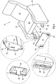
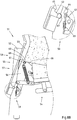
- a detail of a chair 1 in the form of a chair is shown schematically. Both the upholstery of the chair 1 and the backrest of the chair 1 has been neglected. Shown is in particular a frame 2, which gives the seating 1 structure and support, two side panels 3 and an attachment 4 in the form of a seat.
- the frame 2 is fixed on both sides to the side parts 3 and comprises a pivot fitting 5 for pivoting the chair 1, so that the user of the chair 1 can take several comfortable positions on the seating 1.
- the frame 2 comprises two lateral connecting elements 6 in the form of rails for mounting the attachment 4 in the form of the seat.
- the attachment 4 in turn comprises a peripheral frame 7, which can be mounted on the connecting elements 6.
- a mounting portion 8 is provided on both sides of the frame 2, which provides two connections 9,10.
- the first connection 9 is assigned to the rear side of the attachment 4 and the second connection 10 to the front side of the attachment 4 in the form of the seat.
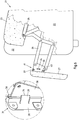
- the seating 1 is shown in a sectional view with a partially mounted attachment 4 with a pad 11.
- the first connection 9 is already closed, while the second connection 10 is still unconnected.
- the first connection 9 is formed by a plug connection comprising a pin element 12 and a hook section 13, wherein the hook section 13 can be plugged onto the pin element 12.
- the pin member 12 is inserted in the hook portion 13.
- the hook portion 13 has an opening which corresponds approximately to the vertical extent of the pin member 12 in the vertical direction.
- the first connection 9 is thus essentially free of play in this direction.
- Both upwards and downwards, the first connection 9 forms a positive connection between the pin element 12 and the hook section 13. However, this positive connection still allows pivoting of the first connection 9. This is when shown and so far preferred seating 1 the attachment 4 pivoted about the pin member 12. In this way, the front end of the attachment 4 can be pivoted downwards in the direction of the frame 2.
- the hook portion 13 forms a receptacle 14 in the form of a groove, wherein the pin member 12 rests positively on the groove base. In this way, an alignment of the attachment 4 is achieved in the horizontal direction. If the front end of the attachment part 4 is pivoted downward about the first connection 9, a latching lug 15 enters the corrsponding connection element 6 in the form of a rail. As a result, the locking lug 15 is pressed inwards and slides inside on the connecting element 6 until the latching lug 15 reaches the undercut 16 of the second connection 10 and then engages behind the undercut 16 of the second connection 10. Thus, the locking lug 15 engages positively behind the undercut 16 and the second connection 10 is closed, as shown in the Fig. 3 is shown.
- the first link 9 forms a positive connection in a vertical direction upward, in a vertical direction downward and in a horizontal direction forward.
- the terms horizontal and vertical are used herein, on condition that the seating 1 rises on a horizontal and level surface.
- the directions horizontally and vertically can therefore be regarded within certain limits as relative. However, this is sufficient to clearly distinguish the corresponding directions.
- the corresponding spatial directions are preferably perpendicular to each other.
- the connecting elements 18, 19 of the first connection 9 and the second connection 10 assigned to the attachment 4 are made of plastic.
- the frame 2 associated with the connecting elements 6 of the first and the second connection 9,10, however, are made of metal.
- the connecting elements 6 of the frame 2 need not be formed as continuous rails.
- the connecting elements 6 can also be provided in several parts and separately from each other.
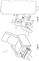
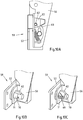
- a seat 21 is shown in the form of an armchair, the two side parts 22, a seat 23, a backrest 24 and a substantially disposed below the seat 23 frame 25 has.
- the frame 25 is fixed to the two side parts 22 and carries the seat 23 and the backrest 24.
- the frame 25 also includes a pivot fitting 26, on which another attachment 27 of the chair 21 in the form of a foot portion of a downwardly pivoted non-use position in a pivoted upward pivoted position of use.
- the attachment 27 is fixed on both sides of the attachment 27 on the pivot fitting 26 via two mounting units 28,29.
- the swivel fitting 26 and the frame 25 have a corresponding thereto Connecting elements 30, each of which together provide two connections 31,32.
- the connecting element 30 provided on the swivel fitting 26 is formed from a flat steel and has a receptacle 33 of a first connection 31 and an undercut 34 of a second connection 10.
- the receptacle 33 is groove-shaped.
- a hook portion 35 adjoins the receptacle 33.
- the groove-shaped receptacle 33 has, in the direction of the groove base, tapered groove flanks 36 or flanks of the receptacle 33 into which a spring element 37 of the corresponding connecting element 28, 29 of the attachment 27 can engage.
- the connecting element 28,29 of the attachment 27 is made of plastic and designed so that the connecting element 30 of the frame 25 is guided during the pivoting about the first connection 9 in the slot-shaped receptacle 38.
- the connecting element 30 of the frame 25 can be inserted in different ways into the receptacle 38 of the connecting element 28, 29 of the attachment 27. This can be done so that the connecting element 30 of the frame 25 already when inserting into the receptacle 38 of the attachment 30, the locking lug 39 urges aside.
- the connecting element 30 of the frame 25 can also only when pivoting about the first connection 31 against the detent 39 and push them to the side. In both cases acts on the locking lug 39, a restoring force, which ensures that the locking lug 39 the Undercut 34 engages behind when the connecting element 30 of the frame 25 has been completely pivoted into the receptacle 38 of the attachment 28,29.
- second connection 32 forms in addition to the latching connection and the positive connection to a withdrawal of the connecting element 30 of the frame 25 from the connecting element 28,29 of the attachment 27 still a positive connection in a direction perpendicular thereto.
- the connecting element 28, 29 of the attachment 27 has a stop 40 for the connecting element 30 of the frame 25.
- the abutment of the spring element 37 at the groove bottom of the receptacle 33 of the connecting element 30 of the frame 25 forms a positive connection.
- the attachment 27 facing edge 36 of the receptacle 33 of the connecting element 30 of the frame 25 with the recorded in the receptacle 33 spring member 37 forms a positive connection in a direction perpendicular thereto. Due to the substantially precise engagement of the connecting element 30 of the frame 25 in the connecting element 28,29 of the attachment 27 and a positive connection in the two transverse directions, that is in the direction of the side parts 22 of the chair 21, is provided.
- FIG. 7A-B Seating furniture 41 shown two attachment parts 27 are shown in the form of foot parts, which can be connected via the previously described connecting elements 28,29,30 with the frame 25. This is done in addition to the manner also described above, which is why this in connection with the embodiment according to Fig. 7A-B will not be explained again in detail.
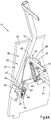
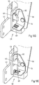
- a detail of a chair 51 is shown schematically.
- the upholstery has been omitted in this seating 51.
- only a part of the right rear side of the seat 51 is shown with a side part 52 and the connection of an attachment 53 in the form of a backrest to a frame 54 of the chair 51, which in the extent preferred seating 51 at the two side parts 52 is supported.
- the connection of the attachment 53 to the frame 54 of the seat 51 is a mounting unit 55, which is provided in the same manner on the side part, not shown.
- the mounting unit 55 comprises a connecting element 56 of the frame 54 and a connecting element 57 of the mounting part 53, which together provide a first connection 58 and a second connection 59.
- the first connection 58 is a plug connection, which is closed by attaching the connecting element 57 of the attachment 53 to the connecting element 56 of the frame 54.
- the connecting element 56 of the frame 54 has a groove-shaped receptacle 60 into which a pin element 61 of the connecting element 57 of the attachment 53 can be positively inserted in the form of a cross member, until the pin member 61 in abutment against a bottom of the receptacle 60 212. the groove bottom same.
- the attachment 53 In the inserted state there is a positive connection between the attachment 53 and the connecting element 56 and the frame 54 in a vertical direction down, a horizontal direction to the front and in a horizontal direction to the rear. Since both the groove bottom of the receptacle 60 and the receptacle 60 received in the pin member 61 are rounded, the attachment 53 can be pivoted about the first connection 58 to close the second connection 59, which is a snap-in connection ,
- the second connection 59 is shown in the closed state.
- the connecting element 56 of the frame 54 has a latching nose 62 which can engage behind an undercut 63 of the connecting element 57 of the attachment 53 when the attachment 53 is pivoted far enough back around the first connection 58.
- a pivoting back of the attachment 53 is prevented as a result of the positive engagement caused by the locking.
- the form-fitting acts, for example, in a horizontal direction to the rear.
- the engaging behind the undercut 63 by the latch 62 also leads to a positive connection in a direction vertically upwards.
- connecting elements 56, 57 of attachment 53 and frame 54 have abutment surfaces 64, 65 on, which bear against each other in the latched state of the second connection 59 and so ensure a positive connection in a horizontal direction forward.
- a positive connection in the horizontal direction to the left is achieved by the installation of the connecting elements 56, 57 in the region of the first connection 58.
- Analog is provided by the second mounting unit on the other side part a positive connection in the horizontal direction to the right. This is therefore unnecessary in the illustrated assembly unit 55.
- the connecting element 57 of the attachment 53 has an inclined guide surface 67 in the region of the second connection 59, which effects a forced alignment, while this on a corresponding guide surface 66 of the connecting element 56 of the frame 54 in the region of the second connection 59 is passed.
- the guide surfaces 66, 67 come into contact with one another and slide against one another.
- connection of the attachment 53 with the connecting element 56 or with the frame 54 can also be done by the attachment 53 and the pin member 61 is placed in the form of the cross member on the frame 54, approximately on the upper surface 68th Then, the attachment 53 are moved until the pin member 61 passes into the receptacle 60 of the frame 54 due to gravity. In this way, the first connection 58 is closed. Subsequently, the attachment 53 can be pivoted about the first connection 58 around. If necessary, the guide surfaces 66,67 come into abutment with each other to align the attachment 53. A further pivoting then automatically leads to a latching of the latching lug 62 and the undercut 63 of the second connection 59 in the form of a latching connection.
- the latching lug 62 is spring-loaded by the spring means 69.
- the latching lug 62 is engaged by the connecting element 57 of the attachment 53 when the second connection 59 is closed and thus lifted upwards, against the restoring force of the spring element 69.
- the locking lug 62 passes as a result of the restoring force of the spring means 69 in the undercut 63 of the connecting element 57 of the attachment 53.
- FIG. 10A-E Alternative embodiments of the second connection 59 in the form of a latching connection between the attachment 53 and the frame 54 are shown. For simplicity, the same reference numerals are used for the same components.
- the locking connection according to Fig. 10A the locking lug 62 is deflected on the connecting element 56 of the frame 54 by the designedg facedde connecting element 57 of the attachment 53 against the restoring force of a spring member 69 down.
- the undercut 63 of the connecting element 57 is above the latching lug 62 in the form of a pin or bolt, the latching lug 62 snaps into the undercut 63.
- the connecting element of the attachment could also be spring-loaded, so that the connecting element of the attachment and not the latch of the connecting element of the frame must be deflected.
- the detent may also be provided on the connecting element of the attachment and the undercut on the connecting element of the frame.
- a latching lug 62 is shown, which is held in a bolt 70. If the bolt 70 is guided through an opening 71 in the connecting element 56 of the frame 54, then the latching lug 62 can be pressed against the restoring force of a spring means 69 in the bolt 70. Behind the opening 71, the latching lug 69 is pushed out of the bolt 70 again as a result of the restoring force of the spring element 69, as a result of which the latching of the second connection 59 is achieved.
Landscapes
- Chairs For Special Purposes, Such As Reclining Chairs (AREA)
Description
Die Erfindung betrifft ein Sitz- und/oder Liegemöbel, insbesondere Sessel, Sofa, Liege oder Bett, mit einem Gestell und wenigstens einem Anbauteil, wobei das Anbauteil über wenigstens eine Montageeinheit umfassend wenigstens zwei separate Verbindungen mit dem Gestell verbunden ist, wobei die erste Verbindung eine Steckverbindung ist, wobei das Anbauteil im eingesteckten Zustand gegenüber dem Gestell schwenkbar gehalten ist.The invention relates to a seat and / or reclining furniture, in particular armchair, sofa, couch or bed, with a frame and at least one attachment, wherein the attachment is connected via at least one mounting unit comprising at least two separate connections to the frame, wherein the first connection is a plug connection, wherein the attachment is held pivotally in the inserted state relative to the frame.
Sitzmöbel und Liegemöbel werden meist aus einer Reihe vorkonfektionierter Bauteile gefertigt, um den Fertigungsaufwand zu verringern. Dabei weisen die Sitzmöbel und Liegemöbel typischerweise ein strukturgebendes und zur Festigkeit beitragendes Gestell auf, an dem weitere Bauteile, sogenannte Anbauteile, montiert werden. Als Gestell kommen dabei sowohl sehr einfach gestaltete Rahmen als auch Funktionsbeschläge sowie Schwenkbeschläge in Frage, wenn das Sitzmöbel oder das Liegemöbel zwischen unterschiedlichen Stellungen verstellbar ist, um dem Benutzer des Sitzmöbel mehrere bequeme Positionen offerieren zu können.Seating furniture and reclining furniture are usually made from a number of prefabricated components to reduce manufacturing costs. In this case, the seating and reclining furniture typically have a structuring and contributing to the strength of the frame on which other components, so-called attachments are mounted. As a frame, both very simply designed frame and functional fittings and swivel fittings come into question when the seating or reclining furniture between different positions is adjustable to offer the user of the chair several comfortable positions.
Dabei kann es sich bei dem Sitzmöbel oder dem Liegemöbel beispielsweise um einen Sessel, ein Sofa, eine Liege oder ein Bett handeln. Als Anbauteile kommen beispielsweise eine Rückenlehne, ein Sitz, ein Fußteil, eine Armlehne oder ein Seitenteil in Frage. Jedes dieser Anbauteile kann bedarfsweise verstellbar ausgebildet sein und zwar entweder separat oder gemeinsam mit wenigstens einem weiteren Anbauteil.For example, the seating or the reclining furniture can be a chair, a sofa, a couch or a bed. As attachments are, for example, a backrest, a seat, a footboard, an armrest or a side panel in question. Each of these attachments can be made adjustable if necessary, either separately or together with at least one additional attachment.
Ein Sitzmöbel der eingangs genannten Art ist aus der
Auf diese Weise sind aufwendige Schraubverbindungen bei der Montage der Rückenlehne entbehrlich. Allerdings bedarf es eines hohen Maßes an Fingerspitzengefühl und Erfahrung, um die Rückenlehne auf die beschriebene Weise zu montieren. Im Ergebnis besteht daher weiter Bedarf an einer Vereinfachung der Endmontage von Sitz- und/oder Liegemöbeln, um den Kostenaufwand für die Montage von Sitz- und/oder Liegemöbeln insgesamt weiter zu verringern.In this way, complicated screw in the assembly of the backrest can be dispensed with. However, it requires a high degree of tact and experience to mount the backrest in the manner described. As a result, there is a continuing need to simplify the final assembly of seating and / or reclining furniture to further reduce the overall cost of assembling seating and / or reclining furniture.
Diese Aufgabe ist bei einem Sitz- und/oder Liegemöbel nach dem Oberbegriff des Anspruchs 1 durch die Merkmale des Kennzeichens von Anspruch 1 gelöst.This object is achieved in a sitting and / or reclining furniture according to the preamble of
Demnach wird bei der Montage des Sitzmöbels und/oder Liegemöbels zunächst die erste Verbindung zwischen dem Anbauteil und dem Gestell hergestellt. Bei dieser Verbindung handelt es sich zudem um eine Steckverbindung. Eine solche Verbindung lässt sich einfach, schnell und kostengünstig herstellen. Dabei ist es bevorzugt, wenn ein hierfür vorgesehener Abschnitt des Anbauteils in einen dafür ausgebildeten Abschnitt des Gestells eingesteckt wird, um die Montage des Anbauteils zu vereinfachen. Alternativ oder zusätzlich ist aber auch das Gegenteil denkbar. Durch die erste Verbindung sind zudem das Anbauteil und das Gestell wenigstens bedingt gegeneinander ausgerichtet, was die weitere Montage des Anbauteils vereinfacht.Accordingly, the first connection between the attachment and the frame is first produced during assembly of the chair and / or reclining furniture. This connection is also a plug connection. Such a connection can be produced easily, quickly and inexpensively. It is preferred if a section of the attachment provided for this purpose is inserted into a section of the frame designed for this, in order to simplify the mounting of the attachment. Alternatively or additionally, however, the opposite is also conceivable. By the first compound also the attachment and the frame are at least partially aligned with each other, which simplifies the further assembly of the attachment.
Die erste Verbindung ist so ausgebildet, dass sie ein Verschwenken zum Schließen der zweiten Verbindung erlaubt. Weiter vorzugsweise wird eine definierte Anlage des Anbauteils am Gestell durch die erste Verbindung bereitgestellt, so dass ein definiertes Verschwenken der ersten Verbindung sichergestellt werden kann. Die erste Verbindung ist daher insbesondere formschlüssig ausgebildet.The first connection is configured to allow pivoting to close the second connection. Further preferably, a defined abutment of the attachment is provided on the frame by the first connection, so that a defined pivoting of the first connection can be ensured. The first connection is therefore designed in particular form-fitting manner.
Durch das Verschwenken der ersten Verbindung, also insbesondere ein Verschwenken des Anbauteils gegenüber dem Gestell um die erste Verbindung herum, kann dann die zweite Verbindung geschlossen werden. Die erste Verbindung kann hierfür eine Schwenkachse zur Verfügung stellen und zudem der Führung des Anbauteils zum Herstellen der zweiten Verbindung dienen. Dabei kann die erste Verbindung so ausgebildet sein, dass sich die zweite Verbindung beim Verschwenken der ersten Verbindung in die richtige Richtung zwangsweise findet. Die zweite Verbindung kann also durch die erste Verbindung in geeigneter Weise ausgerichtet sein, so dass die zweite Verbindung problemlos geschlossen werden kann.By pivoting the first connection, so in particular a pivoting of the attachment relative to the frame around the first connection around, then the second connection can be closed. The first connection can provide a pivot axis for this purpose and also serve to guide the attachment for producing the second connection. In this case, the first connection may be formed such that the second connection forcibly finds itself in the right direction when pivoting the first connection. The second connection can thus be aligned by the first connection in a suitable manner, so that the second connection can be closed easily.
Die zweite Verbindung ist als Rastverbindung ausgebildet und weist demzufolge eine Rastnase und eine Hinterschneidung auf. Im verbundenen Zustand der zweiten Verbindung hintergreift die Rastnase die Hinterschneidung und verhindert so durch einen entsprechenden Formschluss das versehentliche Trennen der zweiten Verbindung. Das Verrasten der zweiten Verbindung wird durch das Verschwenken der ersten Verbindung herbeigeführt. Die erste Verbindung wird dabei soweit verschwenkt, dass die Rastnase hinter der Hinterschneidung verrastet. Nachdem die Rastnase hinter der Hinterschneidung eingerastet ist, wird durch den sich dadurch ausbildenden Formschluss ein Zurückverschwenken der ersten Verbindung verhindert.The second connection is designed as a latching connection and therefore has a latching nose and an undercut. In the connected state of the second connection, the detent engages behind the undercut and thus prevents accidental disconnection of the second connection by means of a corresponding positive connection. The locking of the second connection is brought about by the pivoting of the first connection. The first connection is pivoted so far that the detent latches behind the undercut. After the locking lug is engaged behind the undercut, the first connection is prevented from swinging back through the form-fit that forms thereby.
Das Anbauteil und das Gestell sind nach dem Schließen der ersten und der zweiten Verbindung unverlierbar miteinander verbunden. Zudem sind die durch die Verbindungen aufnehmbaren Kräfte so hoch, dass ein versehentliches Trennen von Anbauteil und Gestell beim bestimmungsgemäßen Betrieb des Sitzmöbels und/oder des Liegemöbels verhindert wird.The attachment and the frame are captively connected to each other after closing the first and the second connection. In addition, the forces that can be absorbed by the connections are so high that an accidental disconnection of Attachment and frame during normal operation of the chair and / or the reclining furniture is prevented.
Bei einer ersten bevorzugten Ausgestaltung des Sitzmöbels und/oder Liegemöbels bildet die Steckverbindung der ersten Verbindung im eingesteckten Zustand in wenigstens zwei senkrecht zueinander verlaufenden Richtungen einen Formschluss. Auf diese Weise kann eine definierte Positionierung des Anbauteils gegenüber dem Gestell bereitgestellt werden, die ein definiertes Verschwenken der ersten Verbindung ermöglicht. Dies gilt umso mehr, wenn zudem ein Formschluss in einer weiteren Richtung besteht, die entgegengesetzt zu einer der übrigen Richtungen verläuft. Besonders zweckmäßig ist es dabei, wenn der Formschluss in einer Einsteckrichtung besteht. Dabei ist die Einsteckrichtung durch die oder eine Richtung gegeben, in der zum Schließen der ersten Verbindung das Anbauteil in das Gestell eingesteckt wird oder umgekehrt. Durch den Formschluss wird ein weiteres Einstecken verhindert und dem Monteur angezeigt, dass die erste Verbindung etabliert ist. Um eine definierte gegenseitige Positionierung von Anbauteil und Gestell sicherzustellen, bietet es sich weiter an, wenn der Formschluss auch in zwei Richtungen existiert, die senkrecht zur Einschubrichtung und einander entgegengesetzt verlaufen. Um einen allzu losen Sitz des Anbauteils gegenüber dem Gestell zu vermeiden, kann das Anbauteil in wenigstens zwei dieser Richtungen am Gestell anliegen und/oder umgekehrt.In a first preferred embodiment of the seat and / or reclining furniture, the plug connection of the first connection forms a positive connection in the inserted state in at least two mutually perpendicular directions. In this way, a defined positioning of the attachment relative to the frame can be provided, which allows a defined pivoting of the first connection. This is all the more true if in addition there is a positive connection in a further direction, which runs opposite to one of the other directions. It is particularly useful in this case if the positive connection exists in a plug-in direction. In this case, the insertion direction is given by the or a direction in which the attachment is inserted into the frame for closing the first connection or vice versa. The positive connection prevents further insertion and indicates to the fitter that the first connection has been established. In order to ensure a defined mutual positioning of fixture and frame, it continues to be useful if the positive fit also exists in two directions, which are perpendicular to the direction of insertion and opposite to each other. In order to avoid an overly loose fit of the attachment relative to the frame, the attachment can rest in at least two of these directions on the frame and / or vice versa.
Bei dem Anbauteil handelt es sich um einen Sitz, ein Fußteil, eine Armlehne oder ein Seitenteil des Sitzmöbels und/oder Liegemöbels. Die Montage dieser Anbauteile kann nämlich nur bedingt vorkonfiguriert werden. Zudem ist die Montage dieser Anbauteile verhältnismäßig aufwendig. Alternativ oder zusätzlich kann das wenigstens eine Anbauteil an einem Sitzrahmen und/oder einem Schwenkbeschlag des Gestells festgelegt sein. Dies ermöglicht eine hohe Flexibilität hinsichtlich der Einstellbarkeit des Sitzmöbels und/oder Liegemöbels.The attachment is a seat, a footboard, an armrest or a side panel of the chair and / or reclining furniture. The installation of these attachments can namely be preconfigured only conditionally. In addition, the installation of these attachments is relatively expensive. Alternatively or additionally, the at least one attachment can be fixed to a seat frame and / or a swivel fitting of the frame. This allows a high degree of flexibility with regard to the adjustability of the seat and / or reclining furniture.
Um eine hohe Stabilität des Anbauteils zu erreichen und ein Kippen desselben zu verhindern, ist es bevorzugt, wenn das Anbauteil über zwei Montageeinheiten mit dem Gestell verbunden ist. Dabei sind die beiden Montageeinheiten vorzugweise an gegenüberliegenden Seiten des Anbauteils und/oder des Gestells vorgesehen.In order to achieve a high stability of the attachment and prevent tilting thereof, it is preferred if the attachment is connected via two mounting units with the frame. The two assembly units are preferably provided on opposite sides of the attachment and / or the frame.
Einfach in der Herstellung und leicht zu fügen ist es, da die erste Verbindung eine Aufnahme und ein formschlüssig in der Aufnahme aufgenommenes Stiftelement umfasst. Die Aufnahme kann dabei der Einfachheit halber nach Art eines Schlitzes ausgebildet sein. Alternativ oder zusätzlich kann bei einer einfachen Ausgestaltung der ersten Verbindung das Stiftelement als eine Art Bolzen ausgebildet sein. Das Stiftelement kann aber auch abweichend dazu ausgebildet sein. Bevorzugt ist es jedoch, wenn das Stiftelement mehr oder weniger problemlos zum Verschwenken der ersten Verbindung, insbesondere in der Aufnahme, drehbar gehalten ist, und zwar vorzugsweise bevor die zweite Verbindung geschlossen ist. Die zweite Verbindung verhindert nämlich vorzugsweise das Schwenken oder Drehen des Stiftelements, so dass das Anbauteil fest am Gestell gehalten ist.It is simple to manufacture and easy to fit because the first connection comprises a receptacle and a pin element received in a form-fitting manner in the receptacle. The recording can be designed for the sake of simplicity in the manner of a slot. Alternatively or additionally, in a simple embodiment of the first connection, the pin element may be formed as a kind of bolt. However, the pin element can also be designed differently. However, it is preferred if the pin element is more or less easily rotatable for pivoting the first connection, in particular in the receptacle, rotatably supported, preferably before the second connection is closed. Namely, the second connection preferably prevents the pivoting or rotation of the pin element, so that the attachment is held firmly on the frame.
Einfach und zweckmäßig ist es, da die Aufnahme nutförmig ausgebildet ist. Dies erleichtert bedarfsweise auch das Einstecken eines Stiftelements in Form eines Federelements des Anbauteils und/oder des Gestells in die nutförmige Aufnahme. Die Aufnahme kann dabei einen Nutgrund aufweisen, der ein weiteres Einstecken verhindert und dem Monteur anzeigt, dass sich die erste Verbindung im eingesteckten Zustand befindet. Um das Einstecken weiter zu vereinfachen, kann sich die Aufnahme in Richtung des Bodens bzw. des Nutgrunds der Aufnahme verjüngen. Einleitend wird also ein leichtes Einstecken ermöglicht, ohne dass eine übermäßig exakte Positionierung erfolgen muss. Im Bereich des Nutgrunds kann so aber gleichzeitig eine exakte zwangsweise Positionierung von Anbauteil und Gestell erreicht werden.Simple and convenient it is because the recording is groove-shaped. This also facilitates, if necessary, the insertion of a pin element in the form of a spring element of the attachment and / or the frame in the groove-shaped receptacle. The receptacle may have a groove bottom, which prevents further insertion and indicates to the fitter that the first connection is in the inserted state. In order to further simplify the insertion, the receptacle can taper in the direction of the bottom or the groove bottom of the receptacle. Initially, therefore, an easy insertion is made possible without an excessively exact positioning must be carried out. In the area of the groove base, however, an exact forced positioning of the attachment and the frame can be achieved at the same time.
Eine einfache Bereitstellung der ersten Verbindung kann auch dadurch erreicht werden, dass die Aufnahme durch einen Hakenabschnitt des Gestells oder des Anbauteils gebildet wird. Dies ist insbesondere dann von Vorteil, wenn die Aufnahme am Anbauteil vorgesehen ist. Dann kann der Einfachheit halber das Stiftelement am Gestell vorgesehen sein, wobei der Hakenabschnitt das Stiftelement umgreifen kann. Wenn der Hakenabschnitt und/oder das Stiftelement eine gewisse Elastizität bereitstellt, kann der Hakenabschnitt beim Umgreifen des Stiftelements mit diesem verrasten.A simple provision of the first connection can also be achieved in that the receptacle is formed by a hook portion of the frame or the attachment. This is particularly advantageous if the recording is provided on the attachment. Then, for simplicity, the pin member may be provided on the frame, wherein the hook portion may engage around the pin member. If the hook portion and / or the pin member provides a certain elasticity, the hook portion can engage in engaging around the pin member with this.
Zur Stabilisierung der zweiten Verbindung und der präziseren Positionierung des Anbauteils bietet es sich an, wenn die zweite Verbindung im verrasteten Zustand wenigstens in zwei senkrecht zueinander stehenden Richtungen einen Formschluss bildet. Ein Formschluss kann dabei durch die Verrastung zwischen der Rastnase und der Hinterschneidung gebildet werden. Es kann dann nicht nur ein Zurückschwenken der ersten Verbindung verhindert, sondern auch ein versehentliches Verschiebung des Anbauteils in wenigstens einer Richtung senkrecht dazu.To stabilize the second connection and the more precise positioning of the attachment, it makes sense if the second connection forms a positive connection in the latched state at least in two mutually perpendicular directions. A positive connection can be formed by the latching between the locking lug and the undercut. It can then not only prevents pivoting back of the first connection, but also an accidental displacement of the attachment in at least one direction perpendicular thereto.
Um auch bei sehr unterschiedlichen Beanspruchungen der ersten Verbindung und der zweiten Verbindung eine dauerhaft stabile Positionierung des Anbauteils gegenüber dem Gestell sicherstellen zu können, können die erste Verbindung und die zweite Verbindung in drei senkrecht aufeinander stehenden Raumrichtungen jeweils wenigstens einen Formschluss bilden. Das Anbauteil kann dann jedenfalls nur begrenzt in eine beliebige Raumrichtung verschoben werden, ohne dass ein weiteres Verschieben durch einen entsprechenden Formschluss blockiert würde. Bedarfsweise kann alleine die erste Verbindung oder die zweite Verbindung einen Formschluss in alle drei senkrecht zueinander stehenden Raumrichtungen aufweisen. Zwingend erforderlich ist dies jedoch nicht. Es kann aber sehr wohl zu einer besseren Arretierung des Anbauteils führen, wenn die erste Verbindung und die zweite Verbindung in wenigstens einer Raumrichtung einen Formschluss bilden. Auf diese Weise kann eine doppelte Absicherung erreicht und können zudem höhere Kräfte aufgenommen werden.In order to ensure a permanently stable positioning of the attachment relative to the frame even with very different stresses on the first connection and the second connection, the first connection and the second connection can form at least one positive connection in three mutually perpendicular spatial directions. The attachment can then be moved only limited in any direction in space, without any further movement would be blocked by a corresponding positive connection. If necessary, alone the first connection or the second connection can have a positive connection in all three mutually perpendicular spatial directions. However, this is not absolutely necessary. But it can very well lead to a better locking of the attachment when the first connection and the second connection form a positive connection in at least one spatial direction. In this way, a double protection can be achieved and also higher forces can be absorbed.
Alternativ oder zusätzlich kann die wenigstens eine Montageeinheit ein Verbindungselement mit der Aufnahme der ersten Verbindung und der Hinterschneidung der zweiten Verbindung aufweisen. Die Aufnahme und die Hinterschneidung können somit in einem Bauteil zusammengeführt werden, um den konstruktiven Aufwand zu senken. Zu diesem Zweck ist es besonders bevorzugt, wenn das Verbindungselement einteilig ausgebildet ist. Noch einfacher und kompakter kann es sein, wenn das Verbindungselement einstückig ausgebildet ist. In diesem Zusammenhang kann das Verbindungselement der Einfachheit halber als ein Flachprodukt oder Flachprofil, insbesondere ein metallisches Flachprodukt, wie ein Stahlblech, ausgebildet sein.Alternatively or additionally, the at least one mounting unit can be a connecting element with the receptacle of the first connection and the Undercut the second connection. The receptacle and the undercut can thus be brought together in one component to reduce the design effort. For this purpose, it is particularly preferred if the connecting element is formed in one piece. Even simpler and more compact it can be when the connecting element is integrally formed. In this context, the connecting element for the sake of simplicity as a flat product or flat profile, in particular a metallic flat product, such as a steel sheet may be formed.
Alternativ oder zusätzlich kann das Verbindungselement in einer Aufnahme einer weiteren Verbindungseinheit aufgenommen sein. Die weitere Verbindungseinheit kann dann ebenfalls konstruktiv einfach und kompakt ausgebildet sein. Um weitere Bauteile einzusparen, können die erste Verbindungseinheit und die zweite Verbindungeinheit gemeinsam die erste Verbindung und die zweite Verbindung bilden. Eine einfache Fertigung der weiteren Verbindungseinheit und eine gute Verbindbarkeit mit der ersten Verbindungseinheit kann erreicht werden, wenn die zweite Verbindungeinheit aus Kunststoff gebildet ist. Dann kann weiter vorzugweise aufgrund der Elastizität des Kunststoffs die zweite Verbindungseinheit die Rastnase aufweisen, was die Verrastung der Rastnase mit der Hinterschneidung vereinfacht.Alternatively or additionally, the connecting element can be accommodated in a receptacle of a further connecting unit. The further connection unit can then also be structurally simple and compact. In order to save further components, the first connection unit and the second connection unit may together form the first connection and the second connection. A simple production of the further connection unit and a good connectability with the first connection unit can be achieved if the second connection unit is formed from plastic. Then, further preferably due to the elasticity of the plastic, the second connection unit have the latching lug, which simplifies the latching of the latching lug with the undercut.
Grundsätzlich kann die Rastnase der zweiten Verbindung jedoch derart vorgesehen sein, dass die Rastnase beim Schließen der ersten Verbindung gegen eine Rückstellkraft aus einer Ausgangsstellung verschoben und/oder verschwenkt wird. Die Rastnase kann also so vorgesehen sein, dass durch Annäherung des Anbauteils und des Gestells beim Einstecken des Anbauteils in das Gestell und/oder umgekehrt die Rastnase zwangsweise ausgelenkt wird. Die dabei aufgeprägte Rückstellkraft sorgt dann dafür, dass die Rastnase ohne weiteres Zutun hinter der Hinterschneidung einrastet, wenn die zweite Verbindung geschlossen wird.In principle, however, the latching lug of the second connection can be provided in such a way that when the first connection is closed the latching lug is displaced and / or pivoted against a restoring force from an initial position. The locking lug can therefore be provided so that the locking lug is forcibly deflected by approach of the attachment and the frame when inserting the attachment in the frame and / or vice versa. The thereby restoring force then ensures that the latch snaps without further action behind the undercut when the second connection is closed.
Alternativ oder zusätzlich kann vorgesehen werden, dass die Rastnase der zweiten Verbindung derart vorgesehen ist, dass die Rastnase beim Verschwenken der ersten Verbindung zum Schließen der zweiten Verbindung gegen eine Rückstellkraft aus einer Ausgangsstellung verschoben und/oder verschwenkt wird. Die Rastnase kann also so vorgesehen sein, dass durch das gegenseitige Verschwenken von Anbauteil und Gestell bei geschlossener erster Verbindung und/oder im eingesteckten Zustand der ersten Verbindung zwangsweise eine Auslenkung der Rastnase bewirkt wird, die zu einer Vorspannung führt. Die entsprechende Rückstellkraft sorgt dann dafür, dass die Rastnase ohne weiteres Zutun hinter der Hinterschneidung einrastet, wenn die erste Verbindung weit genug verschwenkt wurde, d.h. wenn die zweite Verbindung geschlossen wird.Alternatively or additionally, it may be provided that the latching lug of the second connection is provided such that the latching lug when pivoting the first Moved connection for closing the second connection against a restoring force from an initial position and / or is pivoted. The locking lug can thus be provided so that by the mutual pivoting of the attachment and frame with closed first connection and / or in the inserted state of the first connection forcibly a deflection of the latch is effected, which leads to a bias. The corresponding restoring force then ensures that the locking lug snaps without further action behind the undercut when the first connection has been pivoted far enough, ie when the second connection is closed.
Damit die zweite Verbindung einfach und schnell gefügt werden kann, kann die zweite Verbindung wenigstens zwei korrespondierende Führungsflächen aufweisen. Die Führungsflächen können jedenfalls bei nicht zufriedenstellender Ausrichtung von Anbauteil und Gestell in Anlage aneinander kommen und beim Fügen der zweiten Verbindung aneinander abgleiten, jedenfalls vor dem Hinterrasten der Hinterschneidung durch die Rastnase. Die Führungsflächen sind dabei insbesondere so aufeinander abgestimmt, dass das Abgleiten der Führungsflächen aneinander beim Fügen der zweiten Verbindung zu einer verbesserten Ausrichtung von Anbauteil und Gestell führt. So kann sichergestellt werden, dass die zweite Verbindung auch bei einleitend mangelhafter Ausrichtung problemlos gefügt werden kann.So that the second connection can be joined easily and quickly, the second connection can have at least two corresponding guide surfaces. The guide surfaces can in any case come in unsatisfactory alignment of attachment and frame in abutment against each other and slide when joining the second connection to each other, at least before the Hinterrasten the undercut by the latch. The guide surfaces are in particular coordinated so that the sliding of the guide surfaces together when joining the second connection leads to improved alignment of fixture and frame. Thus it can be ensured that the second connection can be easily joined even if initially inadequate alignment.
Nachfolgend wird die Erfindung anhand einer lediglich Ausführungsbeispiele darstellenden Zeichnung näher erläutert. In der Zeichnung zeigt
- Fig. 1
- ein erstes erfindungsgemäßes Sitzmöbel mit einem Gestell und einem noch nicht mit dem Gestell verbundenen Anbauteil in einer schematischen und perspektivischen Darstellung,
- Fig. 2
- das Sitzmöbel aus
Fig. 1 mit einer ersten Verbindung zwischen dem Anbauteil und dem Gestell in einer Schnittansicht entlang eines vertikalen Längsschnitts, - Fig. 3
- das Sitzmöbel aus
Fig. 1 in der Darstellung gemäßFig. 2 mit einer ersten und einer zweiten Verbindung zwischen dem Anbauteil und dem Gestell, - Fig. 4
- ein zweites erfindungsgemäßes Sitzmöbel mit einem Gestell und einem noch nicht mit dem Gestell verbundenen Anbauteil in einer schematischen und perspektivischen Darstellung
- Fig. 5
- das Sitzmöbel aus
Fig. 4 mit einer ersten Verbindung zwischen dem Anbauteil und dem Gestell in einer seitlichen Schnittansicht, - Fig. 6
- das Sitzmöbel aus
Fig. 4 in der Darstellung gemäßFig. 5 mit einer ersten und einer zweiten Verbindung zwischen dem Anbauteil und dem Gestell, - Fig. 7A-B
- ein drittes erfindungsgemäßes Sitzmöbel mit einem Gestell und zwei Anbauteilen in einer perspektivischen Darstellung und einer Seitenansicht,
- Fig. 8A-B
- ein viertes erfindungsgemäßes Sitzmöbel mit einer ersten Verbindung zwischen einem Anbauteil und einem Gestell schematisch in einer perspektivischen Darstellung und einer seitlichen Schnittansicht,
- Fig. 9
- das Sitzmöbel aus
Fig. 8 mit einer ersten und einer zweiten Verbindung zwischen dem Anbauteil und dem Gestell in einer seitlichen Schnittansicht und - Fig. 10A-E
- alternative Ausgestaltungen einer zweiten Verbindung zwischen dem Anbauteil und dem Gestell.
- Fig. 1
- a first inventive seating furniture with a frame and a not yet connected to the frame attachment in a schematic and perspective view,
- Fig. 2
- the seating
Fig. 1 with a first connection between the attachment and the frame in a sectional view along a vertical longitudinal section, - Fig. 3
- the seating
Fig. 1 in the illustration according toFig. 2 with a first and a second connection between the attachment and the frame, - Fig. 4
- a second inventive seating with a frame and a not yet connected to the frame attachment in a schematic and perspective view
- Fig. 5
- the seating
Fig. 4 with a first connection between the attachment and the frame in a side sectional view, - Fig. 6
- the seating
Fig. 4 in the illustration according toFig. 5 with a first and a second connection between the attachment and the frame, - Fig. 7A-B
- a third inventive seating furniture with a frame and two attachments in a perspective view and a side view,
- Fig. 8A-B
- a fourth inventive seating furniture with a first connection between an attachment and a frame schematically in a perspective view and a side sectional view,
- Fig. 9
- the seating
Fig. 8 with a first and a second connection between the attachment and the frame in a side sectional view and - Fig. 10A-E
- alternative embodiments of a second connection between the attachment and the frame.
In der
Dabei umfasst das Gestell 2 zwei seitliche Verbindungselemente 6 in Form von Schienen zur Montage des Anbauteils 4 in Form des Sitzes. Das Anbauteil 4 umfasst seinerseits einen umlaufenden Rahmen 7, der auf den Verbindungselementen 6 montiert werden kann. Hierzu ist an beiden Seiten des Gestells 2 jeweils ein Montageabschnitt 8 vorgesehen, der zwei Verbindungen 9,10 bereitstellt. Beim dargestellten und insoweit bevorzugten Sitzmöbel 1 ist die erste Verbindung 9 der Rückseite des Anbauteils 4 und die zweite Verbindung 10 der Vorderseite des Anbauteils 4 in Form des Sitzes zugeordnet.In this case, the
In der
Durch die Aufnahme des Stiftelements 12 im Hakenabschnitt 13 jeweils der ersten Verbindung 9 wird auch ein Formschluss in horizontaler Richtung nach vorne geschaffen. Der Hakenabschnitt 13 bildet dabei eine Aufnahme 14 in Form einer Nut, wobei das Stiftelement 12 formschlüssig am Nutgrund anliegt. Auf diese Weise wird eine Ausrichtung des Anbauteils 4 in horizontaler Richtung erreicht. Wird das vordere Ende des Anbauteils 4 um die erste Verbindung 9 nach unten geschwenkt, gelangt eine Rastnase 15 in das korrspondierende Verbindungselement 6 in Form einer Schiene. Dadurch wird die Rastnase 15 nach innen gedrückt und gleitet innen am Verbindungselement 6 ab, bis die Rastnase 15 die Hinterschneidung 16 der zweiten Verbindung 10 erreicht und sodann hinter die Hinterschneidung 16 der zweiten Verbindung 10 hintergreift. Somit rastet die Rastnase 15 formschlüssig hinter der Hinterschneidung 16 ein und die zweite Verbindung 10 wird geschlossen, wie dies in der
Parallel dazu greifen beim dargestellten und insoweit bevorzugten Sitzmöbel 1 weitere Elemente 17 der zweiten Verbindung 10 des Verbindungselements 18 des Anbauteils 4 in das Verbindungselement 6 des Gestells 2 in Form der Schiene ein, um einen Formschluss jeweils in Richtung zu den Seiten des Sitzmöbels 1 zu bilden. Zudem sitzen die entsprechenden Elemente 17 des Verbindungselements 18 des Anbauteils 4 im verrasteten Zustand der zweiten Verbindung 10 auf dem Verbindungselement 6 des Gestells 2 auf. Mithin wird durch die zweite Verbindung 10 ein Formschluss vertikal nach unten und horizontal zu beiden Seiten erreicht. Über das Eingreifen der Rastnase 15 in die Hinterschneidung 16 wird zudem ein Formschluss in vertikaler Richtung nach oben und in horizontaler Richtung nach vorne und nach hinten bereitgestellt.At the same time, in the case of the
Dagegen bildet die erste Verbindung 9 einen Formschluss in einer vertikalen Richtung nach oben, in einer vertikalen Richtung nach unten und in einer horizontalen Richtung nach vorne. In diesem Zusammenhang werden vorliegend der besseren Verständlichkeit halber die Begriffe horizontal und vertikal verwendet, und zwar unter der Voraussetzung, dass das Sitzmöbel 1 auf einem horizontalen und ebenen Untergrund aufsteht. Die Richtungen horizontal und vertikal können vorliegend also in gewissen Grenzen als relativ angesehen werden. Dies reicht aber aus, um die entsprechenden Richtungen eindeutig voneinander zu unterscheiden. Außerdem stehen die entsprechenden Raumrichtungen vorzugsweise senkrecht aufeinander.On the other hand, the
Beim dargestellten und insoweit bevorzugten Sitzmöbel sind die dem Anbauteil 4 zugeordneten Verbindungselemente 18,19 der ersten Verbindung 9 und der zweiten Verbindung 10 aus Kunststoff gefertigt. Die dem Gestell 2 zugeordneten Verbindungselemente 6 der ersten und der zweiten Verbindung 9,10 sind dagegen aus Metall gefertigt. In diesem Zusammenhang ist auch zu beachten, dass die Verbindungelemente 6 des Gestells 2 nicht als durchgängige Schienen ausgebildet sein müssen. Die Verbindungelemente 6 können auch mehrteilig und separat voneinander vorgesehen sein.In the case of the seating furniture which is preferred and preferred, the connecting
In der
Beim dargestellten und insoweit bevorzugten Sitzmöbel 21 weisen der Schwenkbeschlag 26 und das Gestell 25 hierzu korrespondierende Verbindungselemente 30 auf, die jeweils gemeinsam zwei Verbindungen 31,32 bereitstellen. Das am Schwenkbeschlag 26 vorgesehene Verbindungselement 30 ist aus einem Flachstahl gebildet und weist eine Aufnahme 33 einer ersten Verbindung 31 und eine Hinterschneidung 34 einer zweiten Verbindung 10 auf. Die Aufnahme 33 ist dabei nutförmig ausgebildet. Zudem grenzt ein Hakenabschnitt 35 an die Aufnahme 33 an. Die nutförmige Aufnahme 33 weist in Richtung des Nutgrunds sich verjüngende Nutflanken 36 bzw. Flanken der Aufnahme 33 auf, in die ein Federelement 37 des korrespondierenden Verbindungselements 28,29 des Anbauteils 27 eingreifen kann.In the case of the
Dazu wird, wie in der
Das Verbindungselement 28,29 des Anbauteils 27 ist aus Kunststoff gefertigt und so ausgebildet, dass das Verbindungselement 30 des Gestells 25 während des Verschwenkens um die erste Verbindung 9 in der schlitzförmigen Aufnahme 38 geführt wird. Dabei kann das Verbindungselement 30 des Gestells 25 auf unterschiedliche Weisen in die Aufnahme 38 des Verbindungselements 28,29 des Anbauteils 27 eingesteckt werden. Dies kann so erfolgen, dass das Verbindungselement 30 des Gestells 25 bereits beim Einstecken in die Aufnahme 38 des Anbauteils 30 die Rastnase 39 zur Seite drängt. Das Verbindungselement 30 des Gestells 25 kann aber auch erst beim Verschwenken um die erste Verbindung 31 gegen die Rastnase 39 stoßen und diese zur Seite drängen. In beiden Fällen wirkt auf die Rastnase 39 eine Rückstellkraft, die dafür sorgt, dass die Rastnase 39 die Hinterschneidung 34 hintergreift, wenn das Verbindungselement 30 des Gestells 25 ganz in die Aufnahme 38 des Anbauteils 28,29 eingeschwenkt worden ist.The connecting
Die in der
Bei dem in den
In den
Im eingesteckten Zustand besteht ein Formschluss zwischen dem Anbauteil 53 und dem Verbindungselement 56 bzw. dem Gestell 54 in einer vertikalen Richtung nach unten, einer horizontalen Richtung nach vorne sowie in einer horizontalen Richtung nach hinten. Da sowohl der Nutgrund der Aufnahme 60 als auch das in der Aufnahme 60 aufgenommene Stiftelement 61 abgerundet ausgebildet sind, kann das Anbauteil 53 um die erste Verbindung 58 verschwenkt werden, um auch die zweite Verbindung 59 zu schließen, bei der es sich um eine Rastverbindung handelt.In the inserted state there is a positive connection between the
In der
Beim dargestellten und insoweit bevorzugten Sitzmöbel 51 weist das Verbindungselement 57 des Anbauteils 53 im Bereich der zweiten Verbindung 59 eine geneigte Führungsfläche 67 auf, die eine zwangsweise Ausrichtung bewirkt, während diese an einer korrespondierenden Führungsfläche 66 des Verbindungselements 56 des Gestells 54 im Bereich der zweiten Verbindung 59 vorbeigeführt wird. Bei einer fehlerhaften Ausrichtung der Verbindungselemente 56,57 zueinander gelangen die Führungsflächen 66,67 aneinander in Anlage und gleiten aneinander ab.In the case of the
Das Verbinden des Anbauteils 53 mit dem Verbindungselement 56 bzw. mit dem Gestell 54 kann auch erfolgen, indem das Anbauteil 53 bzw. das Stiftelement 61 in Form des Querträgers auf das Gestell 54 aufgesetzt wird, etwa auf die obere Fläche 68. Dann kann das Anbauteil 53 verschoben werden, bis das Stiftelement 61 infolge der Schwerkraft in die Aufnahme 60 des Gestells 54 gelangt. Auf diese Weise wird die erste Verbindung 58 geschlossen. Anschließend kann das Anbauteil 53 um die erste Verbindung 58 herum geschwenkt werden. Bedarfsweise gelangen die Führungsflächen 66,67 in Anlage aneinander, um das Anbauteil 53 auszurichten. Ein weiteres Verschwenken führt dann automatisch zu einem Verrasten der Rastnase 62 und der Hinterschneidung 63 der zweiten Verbindung 59 in Form einer Rastverbindung.The connection of the
Beim dargestellten und insoweit bevorzugten Sitzmöbel 51 ist die Rastnase 62 federbelastet durch das Federmittel 69. Die Rastnase 62 wird beim Schließen der zweiten Verbindung 59 vom Verbindungelement 57 des Anbauteils 53 untergriffen und somit nach oben angehoben, und zwar gegen die Rückstellkraft des Federelements 69. Anschließend gelangt die Rastnase 62 infolge der Rückstellkraft des Federmittels 69 in die Hinterschneidung 63 des Verbindungelements 57 des Anbauteils 53. Durch Anheben der Rastnase 62 gegen die Rückstellkraft des Federmittels 69 und Zurückverschwenken des Anbauteils 53 kann die zweite Verbindung 59 wieder getrennt werden.In the case of the
In den
In den
Bei dem in den
Claims (15)
- Seating furniture (1, 21, 41) and/or reclining furniture, comprising a frame (2, 25) and at least one mounting part (4, 27) in the form of a seat, a foot part, an arm rest or a side part arranged at the side of a backrest, the mounting part (4, 27) being connected to the frame (2, 25) by means of at least one mounting unit (28, 29) having at least two separate connections (9, 10, 31, 32), the first connection (9, 31) being a plug-in connection, the second connection (10, 32) being a snap connection having a detent (15, 39) and an undercut (16, 34) behind which the detent (15, 39) engages, and the detent (15, 39) and the undercut (16, 34) of the second connection (10, 32) being able to be locked by pivoting the first connection (9, 31) in the plugged in state and, when locked, blocking the first connection (9, 31) from being pivoted back,
characterised in that
in the plugged in state, the mounting part (4, 27) is held pivotally with respect to the frame (2, 25), and in that the first connection (9, 31) has a groove-shaped receiving portion (14, 33) and a pin element (12, 37) which is received in the receiving portion (14, 33) in an interlocking manner. - Seating and/or reclining furniture according to Claim 1,
characterised in that
in the plugged in state, the first connection (9, 31) forms an interlocking fit in a plug-in direction and at least one additional direction which is perpendicular to the plug-in direction. - Seating and/or reclining furniture according to either Claim 1 or 2,
characterised in that
the mounting part (4, 27, 53) is fixed to a seat frame and/or a pivot fitting (5, 26) of the frame (2, 25, 54). - Seating and/or reclining furniture according to any one of Claims 1 to 3,
characterised in that
the mounting part (4, 27) is connected to the frame (2, 25) by means of two mounting units (28, 29). - Seating and/or reclining furniture according to any one of Claims 1 to 4,
characterised in that
the first connection (9, 31) comprises an elongate receiving portion (14, 33) and a pin element (12, 37) which is received in the receiving portion (14, 33) in an interlocking manner. - Seating and/or reclining furniture according to Claim 5,
characterised in that
the receiving portion (14, 33) is tapered towards the bottom of the receiving portion (14, 33). - Seating and/or reclining furniture according to either Claim 5 or 6,
characterised in that
the receiving portion (14, 33) is formed by a hook portion (13, 35) of the frame (2, 25) or of the mounting part (4, 27). - Seating and/or reclining furniture according to any one of Claims 1 to 7,
characterised in that
when locked, the second connection (10, 32) has at least one interlocking fit in a direction which is perpendicular to the interlocking fit formed by the engagement between the detent (15, 39) and the undercut (16, 34). - Seating and/or reclining furniture according to any one of Claims 1 to 8,
characterised in that
the first and the second connection (9, 10, 31, 32) form at least one interlocking fit in each case in three spatial directions which are perpendicular to one another. - Seating and/or reclining furniture according to any one of Claims 5 to 9,
characterised in that
the at least one mounting unit (28, 29) has a connecting element (6, 18, 19, 28, 29, 30) comprising the receiving portion (14, 33) of the first connection (9, 31) and the undercut (16, 34) of the second connection (10, 32). - Seating and/or reclining furniture according to Claim 10,
characterised in that
the connecting element (30) is formed from a, preferably metal, flat profile. - Seating and/or reclining furniture according to either Claim 10 or 11,
characterised in that
the connecting element (30) is received in a receiving portion (38) of another connecting element (28, 29) which is preferably formed from plastics material, and in that the connecting element (30) and the additional connecting element (28, 29) form the first and the second connection (31, 32). - Seating and/or reclining furniture according to any of Claims 1 to 12,
characterised in that
the detent (39) of the second connection (32) is provided in such a way that the detent (39) is displaced and/or pivoted out of a starting position against a restoring force when the first connection (31) is closed. - Seating and/or reclining furniture according to any of Claims 1 to 13,
characterised in that
the detent (15, 39) of the second connection (10, 32) is provided in such a way that the detent (15, 39) is displaced and/or pivoted out of a starting position against a restoring force when the first connection is pivoted to close the second connection (10, 32). - Seating and/or reclining furniture according to any of Claims 1 to 14,
characterised in that
the second connection comprises at least two corresponding guide faces for mutually sliding against one another before the locking of the second connection.
Applications Claiming Priority (1)
| Application Number | Priority Date | Filing Date | Title |
|---|---|---|---|
| DE102014002215.3A DE102014002215A1 (en) | 2014-02-20 | 2014-02-20 | Sitting or lying furniture with attachment |
Publications (2)
| Publication Number | Publication Date |
|---|---|
| EP2921079A1 EP2921079A1 (en) | 2015-09-23 |
| EP2921079B1 true EP2921079B1 (en) | 2019-04-03 |
Family
ID=52477666
Family Applications (1)
| Application Number | Title | Priority Date | Filing Date |
|---|---|---|---|
| EP15155573.7A Active EP2921079B1 (en) | 2014-02-20 | 2015-02-18 | Furniture for sitting or lying on with connection part |
Country Status (2)
| Country | Link |
|---|---|
| EP (1) | EP2921079B1 (en) |
| DE (1) | DE102014002215A1 (en) |
Families Citing this family (3)
| Publication number | Priority date | Publication date | Assignee | Title |
|---|---|---|---|---|
| IT201800002948A1 (en) * | 2018-02-22 | 2019-08-22 | Lightson S R L Soc Benefit | CHAIR WITH INTERCHANGEABLE ELEMENTS |
| DE202019100107U1 (en) * | 2019-01-10 | 2020-04-16 | Innotec Motion GmbH | Seating chassis |
| WO2022199181A1 (en) * | 2021-03-22 | 2022-09-29 | 际诺思股份公司 | Furniture assembling assembly and assembled furniture |
Family Cites Families (4)
| Publication number | Priority date | Publication date | Assignee | Title |
|---|---|---|---|---|
| DE4440553C1 (en) * | 1994-11-12 | 1996-03-14 | Sichelschmidt Stanzwerk | Connecting arrangement for two parts of furniture, e.g. arm=rest and chair frame |
| DE20009339U1 (en) | 2000-05-24 | 2001-09-27 | Stanzwerk Wetter Sichelschmidt GmbH & Co. KG, 58300 Wetter | Seating with plug-in back part |
| AU2002220143A1 (en) * | 2000-11-01 | 2002-05-15 | Cascade Designs, Inc. | Adjustable quick release seatback system particularly for use with wheelchairs |
| DE102013104033A1 (en) * | 2013-04-22 | 2014-10-23 | Ferdinand Lusch Gmbh & Co Kg | Seating furniture with easy-to-install backrest |
-
2014
- 2014-02-20 DE DE102014002215.3A patent/DE102014002215A1/en not_active Ceased
-
2015
- 2015-02-18 EP EP15155573.7A patent/EP2921079B1/en active Active
Non-Patent Citations (1)
| Title |
|---|
| None * |
Also Published As
| Publication number | Publication date |
|---|---|
| EP2921079A1 (en) | 2015-09-23 |
| DE102014002215A1 (en) | 2015-08-20 |
Similar Documents
| Publication | Publication Date | Title |
|---|---|---|
| EP3516995B1 (en) | Chairs with vertically adjustable headrest | |
| DE102014108359A1 (en) | Child seat, convertible into several user configurations | |
| DE112014000095T5 (en) | Device for moving a headrest | |
| EP0236891A2 (en) | Folding furniture | |
| DE8436612U1 (en) | Folding armchair | |
| EP2921079B1 (en) | Furniture for sitting or lying on with connection part | |
| EP3031358B1 (en) | Seat with swingable functional part | |
| EP4091502A1 (en) | Backrest support for a seat | |
| EP2796074B1 (en) | Upholstered furniture | |
| EP0743035B1 (en) | Chair, particularly office-chair, with height-adjustable backrest | |
| EP2893843B1 (en) | Seating furniture with head part which can be pivoted using a motor | |
| EP3071845B1 (en) | Lift adjuster and seating and/or lounging furniture with a lift adjuster | |
| EP1649786A1 (en) | Fitting for hinging the slat support members of an undermattress | |
| EP3031359A1 (en) | Seat with swingable functional part | |
| DE102015117461B4 (en) | Support system for adjusting a headrest | |
| DE9311345U1 (en) | CHAIR | |
| DE29617255U1 (en) | Upholstered furniture element | |
| EP1915928A2 (en) | Furniture, in particular seating | |
| DE102018126293B4 (en) | Slatted frame | |
| EP2921082A1 (en) | Seating and/or lying furniture having a chassis and an associated side member | |
| EP2389916A2 (en) | Furniture for adjusting to a standing position | |
| DE102014003516B4 (en) | Furniture with adjustable functional component | |
| EP3850991B1 (en) | Leg support lining | |
| DE202010005963U1 (en) | Seating furniture, in particular seats | |
| DE29617154U1 (en) | Upholstered armchair or upholstered element with adjustable seat and back upholstery |
Legal Events
| Date | Code | Title | Description |
|---|---|---|---|
| PUAI | Public reference made under article 153(3) epc to a published international application that has entered the european phase |
Free format text: ORIGINAL CODE: 0009012 |
|
| AK | Designated contracting states |
Kind code of ref document: A1 Designated state(s): AL AT BE BG CH CY CZ DE DK EE ES FI FR GB GR HR HU IE IS IT LI LT LU LV MC MK MT NL NO PL PT RO RS SE SI SK SM TR |
|
| AX | Request for extension of the european patent |
Extension state: BA ME |
|
| 17P | Request for examination filed |
Effective date: 20160309 |
|
| RBV | Designated contracting states (corrected) |
Designated state(s): AL AT BE BG CH CY CZ DE DK EE ES FI FR GB GR HR HU IE IS IT LI LT LU LV MC MK MT NL NO PL PT RO RS SE SI SK SM TR |
|
| STAA | Information on the status of an ep patent application or granted ep patent |
Free format text: STATUS: EXAMINATION IS IN PROGRESS |
|
| 17Q | First examination report despatched |
Effective date: 20170206 |
|
| GRAP | Despatch of communication of intention to grant a patent |
Free format text: ORIGINAL CODE: EPIDOSNIGR1 |
|
| STAA | Information on the status of an ep patent application or granted ep patent |
Free format text: STATUS: GRANT OF PATENT IS INTENDED |
|
| INTG | Intention to grant announced |
Effective date: 20180606 |
|
| GRAJ | Information related to disapproval of communication of intention to grant by the applicant or resumption of examination proceedings by the epo deleted |
Free format text: ORIGINAL CODE: EPIDOSDIGR1 |
|
| STAA | Information on the status of an ep patent application or granted ep patent |
Free format text: STATUS: EXAMINATION IS IN PROGRESS |
|
| GRAP | Despatch of communication of intention to grant a patent |
Free format text: ORIGINAL CODE: EPIDOSNIGR1 |
|
| STAA | Information on the status of an ep patent application or granted ep patent |
Free format text: STATUS: GRANT OF PATENT IS INTENDED |
|
| INTC | Intention to grant announced (deleted) | ||
| INTG | Intention to grant announced |
Effective date: 20181005 |
|
| GRAS | Grant fee paid |
Free format text: ORIGINAL CODE: EPIDOSNIGR3 |
|
| GRAA | (expected) grant |
Free format text: ORIGINAL CODE: 0009210 |
|
| STAA | Information on the status of an ep patent application or granted ep patent |
Free format text: STATUS: THE PATENT HAS BEEN GRANTED |
|
| AK | Designated contracting states |
Kind code of ref document: B1 Designated state(s): AL AT BE BG CH CY CZ DE DK EE ES FI FR GB GR HR HU IE IS IT LI LT LU LV MC MK MT NL NO PL PT RO RS SE SI SK SM TR |
|
| REG | Reference to a national code |
Ref country code: GB Ref legal event code: FG4D Free format text: NOT ENGLISH |
|
| REG | Reference to a national code |
Ref country code: CH Ref legal event code: EP Ref country code: AT Ref legal event code: REF Ref document number: 1114679 Country of ref document: AT Kind code of ref document: T Effective date: 20190415 |
|
| REG | Reference to a national code |
Ref country code: DE Ref legal event code: R096 Ref document number: 502015008517 Country of ref document: DE |
|
| REG | Reference to a national code |
Ref country code: IE Ref legal event code: FG4D Free format text: LANGUAGE OF EP DOCUMENT: GERMAN |
|
| REG | Reference to a national code |
Ref country code: NL Ref legal event code: MP Effective date: 20190403 |
|
| REG | Reference to a national code |
Ref country code: LT Ref legal event code: MG4D |
|
| PG25 | Lapsed in a contracting state [announced via postgrant information from national office to epo] |
Ref country code: NL Free format text: LAPSE BECAUSE OF FAILURE TO SUBMIT A TRANSLATION OF THE DESCRIPTION OR TO PAY THE FEE WITHIN THE PRESCRIBED TIME-LIMIT Effective date: 20190403 |
|
| PG25 | Lapsed in a contracting state [announced via postgrant information from national office to epo] |
Ref country code: FI Free format text: LAPSE BECAUSE OF FAILURE TO SUBMIT A TRANSLATION OF THE DESCRIPTION OR TO PAY THE FEE WITHIN THE PRESCRIBED TIME-LIMIT Effective date: 20190403 Ref country code: CZ Free format text: LAPSE BECAUSE OF FAILURE TO SUBMIT A TRANSLATION OF THE DESCRIPTION OR TO PAY THE FEE WITHIN THE PRESCRIBED TIME-LIMIT Effective date: 20190403 Ref country code: SE Free format text: LAPSE BECAUSE OF FAILURE TO SUBMIT A TRANSLATION OF THE DESCRIPTION OR TO PAY THE FEE WITHIN THE PRESCRIBED TIME-LIMIT Effective date: 20190403 Ref country code: ES Free format text: LAPSE BECAUSE OF FAILURE TO SUBMIT A TRANSLATION OF THE DESCRIPTION OR TO PAY THE FEE WITHIN THE PRESCRIBED TIME-LIMIT Effective date: 20190403 Ref country code: PT Free format text: LAPSE BECAUSE OF FAILURE TO SUBMIT A TRANSLATION OF THE DESCRIPTION OR TO PAY THE FEE WITHIN THE PRESCRIBED TIME-LIMIT Effective date: 20190803 Ref country code: AL Free format text: LAPSE BECAUSE OF FAILURE TO SUBMIT A TRANSLATION OF THE DESCRIPTION OR TO PAY THE FEE WITHIN THE PRESCRIBED TIME-LIMIT Effective date: 20190403 Ref country code: LT Free format text: LAPSE BECAUSE OF FAILURE TO SUBMIT A TRANSLATION OF THE DESCRIPTION OR TO PAY THE FEE WITHIN THE PRESCRIBED TIME-LIMIT Effective date: 20190403 Ref country code: NO Free format text: LAPSE BECAUSE OF FAILURE TO SUBMIT A TRANSLATION OF THE DESCRIPTION OR TO PAY THE FEE WITHIN THE PRESCRIBED TIME-LIMIT Effective date: 20190703 Ref country code: HR Free format text: LAPSE BECAUSE OF FAILURE TO SUBMIT A TRANSLATION OF THE DESCRIPTION OR TO PAY THE FEE WITHIN THE PRESCRIBED TIME-LIMIT Effective date: 20190403 |
|
| PG25 | Lapsed in a contracting state [announced via postgrant information from national office to epo] |
Ref country code: BG Free format text: LAPSE BECAUSE OF FAILURE TO SUBMIT A TRANSLATION OF THE DESCRIPTION OR TO PAY THE FEE WITHIN THE PRESCRIBED TIME-LIMIT Effective date: 20190703 Ref country code: PL Free format text: LAPSE BECAUSE OF FAILURE TO SUBMIT A TRANSLATION OF THE DESCRIPTION OR TO PAY THE FEE WITHIN THE PRESCRIBED TIME-LIMIT Effective date: 20190403 Ref country code: LV Free format text: LAPSE BECAUSE OF FAILURE TO SUBMIT A TRANSLATION OF THE DESCRIPTION OR TO PAY THE FEE WITHIN THE PRESCRIBED TIME-LIMIT Effective date: 20190403 Ref country code: RS Free format text: LAPSE BECAUSE OF FAILURE TO SUBMIT A TRANSLATION OF THE DESCRIPTION OR TO PAY THE FEE WITHIN THE PRESCRIBED TIME-LIMIT Effective date: 20190403 |
|
| PG25 | Lapsed in a contracting state [announced via postgrant information from national office to epo] |
Ref country code: IS Free format text: LAPSE BECAUSE OF FAILURE TO SUBMIT A TRANSLATION OF THE DESCRIPTION OR TO PAY THE FEE WITHIN THE PRESCRIBED TIME-LIMIT Effective date: 20190803 |
|
| REG | Reference to a national code |
Ref country code: DE Ref legal event code: R097 Ref document number: 502015008517 Country of ref document: DE |
|
| PG25 | Lapsed in a contracting state [announced via postgrant information from national office to epo] |
Ref country code: RO Free format text: LAPSE BECAUSE OF FAILURE TO SUBMIT A TRANSLATION OF THE DESCRIPTION OR TO PAY THE FEE WITHIN THE PRESCRIBED TIME-LIMIT Effective date: 20190403 Ref country code: DK Free format text: LAPSE BECAUSE OF FAILURE TO SUBMIT A TRANSLATION OF THE DESCRIPTION OR TO PAY THE FEE WITHIN THE PRESCRIBED TIME-LIMIT Effective date: 20190403 Ref country code: EE Free format text: LAPSE BECAUSE OF FAILURE TO SUBMIT A TRANSLATION OF THE DESCRIPTION OR TO PAY THE FEE WITHIN THE PRESCRIBED TIME-LIMIT Effective date: 20190403 Ref country code: SK Free format text: LAPSE BECAUSE OF FAILURE TO SUBMIT A TRANSLATION OF THE DESCRIPTION OR TO PAY THE FEE WITHIN THE PRESCRIBED TIME-LIMIT Effective date: 20190403 |
|
| PLBE | No opposition filed within time limit |
Free format text: ORIGINAL CODE: 0009261 |
|
| STAA | Information on the status of an ep patent application or granted ep patent |
Free format text: STATUS: NO OPPOSITION FILED WITHIN TIME LIMIT |
|
| PG25 | Lapsed in a contracting state [announced via postgrant information from national office to epo] |
Ref country code: IT Free format text: LAPSE BECAUSE OF FAILURE TO SUBMIT A TRANSLATION OF THE DESCRIPTION OR TO PAY THE FEE WITHIN THE PRESCRIBED TIME-LIMIT Effective date: 20190403 Ref country code: SM Free format text: LAPSE BECAUSE OF FAILURE TO SUBMIT A TRANSLATION OF THE DESCRIPTION OR TO PAY THE FEE WITHIN THE PRESCRIBED TIME-LIMIT Effective date: 20190403 |
|
| 26N | No opposition filed |
Effective date: 20200106 |
|
| PG25 | Lapsed in a contracting state [announced via postgrant information from national office to epo] |
Ref country code: TR Free format text: LAPSE BECAUSE OF FAILURE TO SUBMIT A TRANSLATION OF THE DESCRIPTION OR TO PAY THE FEE WITHIN THE PRESCRIBED TIME-LIMIT Effective date: 20190403 |
|
| PG25 | Lapsed in a contracting state [announced via postgrant information from national office to epo] |
Ref country code: SI Free format text: LAPSE BECAUSE OF FAILURE TO SUBMIT A TRANSLATION OF THE DESCRIPTION OR TO PAY THE FEE WITHIN THE PRESCRIBED TIME-LIMIT Effective date: 20190403 |
|
| REG | Reference to a national code |
Ref country code: CH Ref legal event code: PL |
|
| GBPC | Gb: european patent ceased through non-payment of renewal fee |
Effective date: 20200218 |
|
| REG | Reference to a national code |
Ref country code: BE Ref legal event code: MM Effective date: 20200229 |
|
| PG25 | Lapsed in a contracting state [announced via postgrant information from national office to epo] |
Ref country code: LU Free format text: LAPSE BECAUSE OF NON-PAYMENT OF DUE FEES Effective date: 20200218 Ref country code: MC Free format text: LAPSE BECAUSE OF FAILURE TO SUBMIT A TRANSLATION OF THE DESCRIPTION OR TO PAY THE FEE WITHIN THE PRESCRIBED TIME-LIMIT Effective date: 20190403 |
|
| PG25 | Lapsed in a contracting state [announced via postgrant information from national office to epo] |
Ref country code: LI Free format text: LAPSE BECAUSE OF NON-PAYMENT OF DUE FEES Effective date: 20200229 Ref country code: CH Free format text: LAPSE BECAUSE OF NON-PAYMENT OF DUE FEES Effective date: 20200229 |
|
| PG25 | Lapsed in a contracting state [announced via postgrant information from national office to epo] |
Ref country code: GB Free format text: LAPSE BECAUSE OF NON-PAYMENT OF DUE FEES Effective date: 20200218 Ref country code: IE Free format text: LAPSE BECAUSE OF NON-PAYMENT OF DUE FEES Effective date: 20200218 Ref country code: FR Free format text: LAPSE BECAUSE OF NON-PAYMENT OF DUE FEES Effective date: 20200229 |
|
| PG25 | Lapsed in a contracting state [announced via postgrant information from national office to epo] |
Ref country code: BE Free format text: LAPSE BECAUSE OF NON-PAYMENT OF DUE FEES Effective date: 20200229 |
|
| REG | Reference to a national code |
Ref country code: AT Ref legal event code: MM01 Ref document number: 1114679 Country of ref document: AT Kind code of ref document: T Effective date: 20200218 |
|
| PG25 | Lapsed in a contracting state [announced via postgrant information from national office to epo] |
Ref country code: AT Free format text: LAPSE BECAUSE OF NON-PAYMENT OF DUE FEES Effective date: 20200218 |
|
| REG | Reference to a national code |
Ref country code: DE Ref legal event code: R082 Ref document number: 502015008517 Country of ref document: DE Representative=s name: COHAUSZ & FLORACK PATENT- UND RECHTSANWAELTE P, DE Ref country code: DE Ref legal event code: R081 Ref document number: 502015008517 Country of ref document: DE Owner name: FERDINAND LUSCH GMBH, DE Free format text: FORMER OWNER: FERDINAND LUSCH GMBH & CO. KG, 33649 BIELEFELD, DE |
|
| PGFP | Annual fee paid to national office [announced via postgrant information from national office to epo] |
Ref country code: DE Payment date: 20220222 Year of fee payment: 8 |
|
| PG25 | Lapsed in a contracting state [announced via postgrant information from national office to epo] |
Ref country code: MT Free format text: LAPSE BECAUSE OF FAILURE TO SUBMIT A TRANSLATION OF THE DESCRIPTION OR TO PAY THE FEE WITHIN THE PRESCRIBED TIME-LIMIT Effective date: 20190403 Ref country code: CY Free format text: LAPSE BECAUSE OF FAILURE TO SUBMIT A TRANSLATION OF THE DESCRIPTION OR TO PAY THE FEE WITHIN THE PRESCRIBED TIME-LIMIT Effective date: 20190403 |
|
| PG25 | Lapsed in a contracting state [announced via postgrant information from national office to epo] |
Ref country code: MK Free format text: LAPSE BECAUSE OF FAILURE TO SUBMIT A TRANSLATION OF THE DESCRIPTION OR TO PAY THE FEE WITHIN THE PRESCRIBED TIME-LIMIT Effective date: 20190403 |
|
| PG25 | Lapsed in a contracting state [announced via postgrant information from national office to epo] |
Ref country code: GR Free format text: LAPSE BECAUSE OF FAILURE TO SUBMIT A TRANSLATION OF THE DESCRIPTION OR TO PAY THE FEE WITHIN THE PRESCRIBED TIME-LIMIT Effective date: 20190403 |
|
| REG | Reference to a national code |
Ref country code: DE Ref legal event code: R119 Ref document number: 502015008517 Country of ref document: DE |
|
| PG25 | Lapsed in a contracting state [announced via postgrant information from national office to epo] |
Ref country code: DE Free format text: LAPSE BECAUSE OF NON-PAYMENT OF DUE FEES Effective date: 20230901 |