EP2920786B1 - Thin web optical media guiding method - Google Patents
Thin web optical media guiding method Download PDFInfo
- Publication number
- EP2920786B1 EP2920786B1 EP13795102.6A EP13795102A EP2920786B1 EP 2920786 B1 EP2920786 B1 EP 2920786B1 EP 13795102 A EP13795102 A EP 13795102A EP 2920786 B1 EP2920786 B1 EP 2920786B1
- Authority
- EP
- European Patent Office
- Prior art keywords
- optical
- storage tape
- guiding wheel
- optical storage
- tape
- Prior art date
- Legal status (The legal status is an assumption and is not a legal conclusion. Google has not performed a legal analysis and makes no representation as to the accuracy of the status listed.)
- Active
Links
- 230000003287 optical effect Effects 0.000 title claims description 135
- 238000000034 method Methods 0.000 title claims description 10
- 238000013500 data storage Methods 0.000 claims description 20
- 239000002184 metal Substances 0.000 claims description 13
- 229910052751 metal Inorganic materials 0.000 claims description 13
- 239000004033 plastic Substances 0.000 claims description 4
- 229920003023 plastic Polymers 0.000 claims description 4
- 229920000139 polyethylene terephthalate Polymers 0.000 claims description 4
- 239000005020 polyethylene terephthalate Substances 0.000 claims description 4
- 239000011112 polyethylene naphthalate Substances 0.000 claims description 3
- FYYHWMGAXLPEAU-UHFFFAOYSA-N Magnesium Chemical compound [Mg] FYYHWMGAXLPEAU-UHFFFAOYSA-N 0.000 claims description 2
- RTAQQCXQSZGOHL-UHFFFAOYSA-N Titanium Chemical compound [Ti] RTAQQCXQSZGOHL-UHFFFAOYSA-N 0.000 claims description 2
- 229910052782 aluminium Inorganic materials 0.000 claims description 2
- XAGFODPZIPBFFR-UHFFFAOYSA-N aluminium Chemical compound [Al] XAGFODPZIPBFFR-UHFFFAOYSA-N 0.000 claims description 2
- 239000004760 aramid Substances 0.000 claims description 2
- 229920003235 aromatic polyamide Polymers 0.000 claims description 2
- 239000011777 magnesium Substances 0.000 claims description 2
- 229910052749 magnesium Inorganic materials 0.000 claims description 2
- -1 polyethylene terephthalate Polymers 0.000 claims description 2
- 239000010936 titanium Substances 0.000 claims description 2
- 229910052719 titanium Inorganic materials 0.000 claims description 2
- 238000005516 engineering process Methods 0.000 description 5
- 239000000463 material Substances 0.000 description 5
- 238000013461 design Methods 0.000 description 4
- 239000000758 substrate Substances 0.000 description 4
- 238000013459 approach Methods 0.000 description 3
- 239000000203 mixture Substances 0.000 description 3
- 230000015572 biosynthetic process Effects 0.000 description 2
- 230000000694 effects Effects 0.000 description 2
- 238000010276 construction Methods 0.000 description 1
- 238000011161 development Methods 0.000 description 1
- 238000010348 incorporation Methods 0.000 description 1
- 239000000696 magnetic material Substances 0.000 description 1
- 238000005259 measurement Methods 0.000 description 1
- 230000000116 mitigating effect Effects 0.000 description 1
- 229920000728 polyester Polymers 0.000 description 1
- 229920000642 polymer Polymers 0.000 description 1
- 239000011148 porous material Substances 0.000 description 1
- 238000000926 separation method Methods 0.000 description 1
- 238000012546 transfer Methods 0.000 description 1
Images
Classifications
-
- G—PHYSICS
- G11—INFORMATION STORAGE
- G11B—INFORMATION STORAGE BASED ON RELATIVE MOVEMENT BETWEEN RECORD CARRIER AND TRANSDUCER
- G11B15/00—Driving, starting or stopping record carriers of filamentary or web form; Driving both such record carriers and heads; Guiding such record carriers or containers therefor; Control thereof; Control of operating function
- G11B15/60—Guiding record carrier
-
- G—PHYSICS
- G11—INFORMATION STORAGE
- G11B—INFORMATION STORAGE BASED ON RELATIVE MOVEMENT BETWEEN RECORD CARRIER AND TRANSDUCER
- G11B15/00—Driving, starting or stopping record carriers of filamentary or web form; Driving both such record carriers and heads; Guiding such record carriers or containers therefor; Control thereof; Control of operating function
- G11B15/18—Driving; Starting; Stopping; Arrangements for control or regulation thereof
- G11B15/26—Driving record carriers by members acting directly or indirectly thereon
- G11B15/32—Driving record carriers by members acting directly or indirectly thereon through the reels or cores on to which the record carrier is wound
-
- G—PHYSICS
- G11—INFORMATION STORAGE
- G11B—INFORMATION STORAGE BASED ON RELATIVE MOVEMENT BETWEEN RECORD CARRIER AND TRANSDUCER
- G11B15/00—Driving, starting or stopping record carriers of filamentary or web form; Driving both such record carriers and heads; Guiding such record carriers or containers therefor; Control thereof; Control of operating function
- G11B15/60—Guiding record carrier
- G11B15/61—Guiding record carrier on drum, e.g. drum containing rotating heads
-
- G—PHYSICS
- G11—INFORMATION STORAGE
- G11B—INFORMATION STORAGE BASED ON RELATIVE MOVEMENT BETWEEN RECORD CARRIER AND TRANSDUCER
- G11B7/00—Recording or reproducing by optical means, e.g. recording using a thermal beam of optical radiation by modifying optical properties or the physical structure, reproducing using an optical beam at lower power by sensing optical properties; Record carriers therefor
- G11B7/002—Recording, reproducing or erasing systems characterised by the shape or form of the carrier
- G11B7/003—Recording, reproducing or erasing systems characterised by the shape or form of the carrier with webs, filaments or wires, e.g. belts, spooled tapes or films of quasi-infinite extent
Definitions
- the present invention relates to devices for storing digital data onto optical media, and in particular, to devices for storing digital storage data onto an optical storage tape.
- Optical storage devices utilize laser light to write and read data to an optically active storage disk that includes one or more optically sensitive layers onto which data is encoded.
- Such disks may or may not be rewritable depending on the specific compositions used on the disk and on the electro-mechanical design of the optical storage device.
- Examples of optical disks include compact disks (CD), DVDs, Ultra Density Optical disks, Blue Ray disks, and the like.
- the typical optical tape medium includes a base film such as polyethylene naphthalate (PEN) over-coated with multiple layers for recording digital data.
- a polymeric imprint layer is usually disposed over the base film.
- the imprint layer is over-coated with a reflective metallic layer that is, in turn, over-coated with a sequence of dielectric layer, phase change layer, and dielectric layer.
- the actual data recording and reading occurs in the phase change layer.
- a pulsed laser beam is projected from an optical head assembly onto the optical tape thereby causing a phase change in the phase change layer that results in data being encoded therein.
- Data encoded onto the optical tape is also read with a laser with the reflective layer reflecting light to a detector.
- optical tape usually includes optical servo marks embossed into the imprint layer along the length of the tape for operating with a servo control system for controlling the optical head.
- Magnetic data storage is another common technology used to store digital information.
- magnetic storage uses magnetic patterns which are encoded onto a magnetically coated surface to store data.
- data is encoded on magnetic media that is a thin web (i.e, a tape) that is wrapped inside of a cartridge.
- Magnetic heads are used to read/write data from the thin web.
- the web is sent through a tape drive and a recording head that is typically magnetic in nature that gets close to the magnetic surface and records data on it.
- data storage disks have much higher storage density because the thin web tends to move in undesired directions. Therefore, registration is very important in the prior art magnetic storage designs.
- the present invention provides improved methods and systems for storing digital data onto optical media with data transfer rates that approach that of optical storage disks.
- the present invention solves one or more problems of the prior art by providing in at least one embodiment an optical storage device according to claim 1.
- the optical storage device includes a feed reel adapter for holding a feed reel having an optical storage tape and a plurality of optical pickup units for reading and writing data to the optical storage tape.
- the optical storage device also includes a guiding wheel for guiding the optical storage tape when the optical storage tape is in the vicinity of the optical pickup units during read and/or write operations.
- the optical storage device also includes a take-up reel adapter for holding a take-up reel that receives the optical storage tape from the guiding wheel. Spatial separation between the optical pickup units and the optical storage tape allows reading and writing of data without touching the optical storage tape.
- the guiding wheel of the present embodiment securely holds the optical storage tape on a circular path during read/write/tracking operations thereby allowing storage densities to approach that of optical disks.
- a method of storing data on an optical storage tape utilizes the optical storage devices set forth above.
- the method includes a step of providing the optical storage tape to a guiding wheel such that the optical storage tape moves along an arced path when the optical storage tape contacts the guiding wheel.
- Data is read or written to the optical storage tape by a plurality of optical pickup units positioned about the guiding wheel.
- the optical storage tape is subsequently received onto a take-up reel.
- Optical data storage device 10 writes to, reads from, and/or tracks optical storage tape 12.
- Optical storage tape 12 includes one or more optical storage layers onto which device 10 encodes digital data.
- Optical pickup units (OPU) 14 read, write, and/or track data to optical storage tape 12.
- OPU optical pickup units
- a feed reel 16 provides the optical storage tape to optical pickup units 14. Feed reel 16 is received and held by feed reel adapter 18.
- Optical storage device 10 also includes guiding wheel 20 that guides the optical storage tape 10 when the optical storage tape 10 is in the vicinity of the optical pickup units 14 during read and/or write and/or tracking operations.
- guiding wheel 20 securely holds optical storage tape 12 on an curved path (i.e., circular path) during read/write/tracking operations thereby allowing storage densities to approach that of optical disks.
- Take-up reel 22 receives the optical storage tape 12 from the guiding wheel 20.
- Take-up reel 22 is held in place by take-up reel adapter 24 which is driven in a circular direction by electric motor 26.
- optical data storage device 10 further optionally includes first guiding post 30 for positioning the storage tape 12 before contacting guiding wheel 20 and second guiding post 32 for positioning optical storage tape 12 after disengaging guiding wheel 20.
- Figure 2A is a top view of an optical storage tape surface while Figure 2B is a cross sectional view of an optical storage tape.
- Optical storage tape 12 includes a plurality of data tracks 40. Although the storage tape is compatible with virtually any number of data tracks, 200 to 600 data tracks are typical. In a refinement, data tracks 40 are configured in a logical track format across a width of the optical storage tape.
- optical storage tape 12 includes substrate base layer 46 having substrate film sides 48, 50.
- base layer 46 is formed from polyester or other polymeric materials. Examples of such materials include, but are not limited to, polyethylene terephthalate (PET), polyethylene naphthalate (PEN), aramid, and the like, and combinations thereof.
- Imprint layer 52 is disposed over substrate film side 50.
- Imprint layer 52 includes imprint layer side 54 and imprint layer side 56 with imprint layer side 54 being more proximate to substrate base layer 46.
- Multilayer data recording section 58 is disposed over imprint layer 52.
- Multilayer data recording section 58 typically includes one or more layers involved in the optical recording of data.
- Multilayer data recording section 58 includes metal layer 60 disposed over imprint layer side 56.
- Metal layer 60 includes metal layer side 62 and metal layer side 64.
- Metal layer side 62 is more proximate to imprint layer 52 than metal layer side 64.
- Multilayer data recording section 58 also includes dielectric layer 70 disposed over metal layer side 64.
- Dielectric layer 70 includes dielectric layer side 72 and dielectric layer side 74 which is more proximate to metal layer 60.
- Multilayer data recording section 58 further includes phase change layer 80 which is disposed over dielectric layer 70.
- Phase change layer 80 includes phase change layer side 52 and phase change layer side 54 which is more proximate to phase change layer 50.
- phase change layer 50 is the actual layer onto which data is encoded by optical tape storage system 10 ( Figure 1 ).
- Multilayer data recording section 58 also includes dielectric layer 90 disposed over metal layer side 54.
- FIG. 3 is a perspective view of a guiding wheel used in the optical tape storage device.
- Figure 4 is a side view of a guiding wheel used in the optical tape storage device.
- Guiding wheel 20 includes a circular outer portion 94 that contacts the storage tape. Spokes 96 connect circular outer portion 20 to inner hub 98.
- Virtually any type of material may be used for the construction of guiding wheel 20.
- non-magnetic materials such as aluminum, magnesium, titanium, plastics, and metal-coated plastics may be used to construct guiding wheel 20.
- guiding wheel 20 includes edge guides 100, 102 for holding the optical storage tape in place.
- FIG. 1 With reference to Figures 1 , 5 and 6 , schematic designs of guiding wheels having reduced air film formation are provided.
- guiding wheel 20 spins about at a high rate. Drag forces and the viscosity of air combine to form an air film that acts to push optical storage tape 12 away from guiding wheel 20.
- One solution for the formation of such air films is the incorporation of one or more grooves that assist in maintaining contact between the optical storage tape and the guiding wheel by providing a space for air to escape into.
- Figure 5 provides a variation of guiding wheel 20 which includes a plurality of grooves 106 into which air can escape into thereby mitigating the effect of an air film being formed.
- Figure 6 provides another variation in which guiding wheel 20 includes central groove 108 into which air can escape thereby reducing the effects of an air film.
- guiding wheel 20 comprises a porous material (e.g. porous metal or polymer) that assists in maintaining contact between the optical storage tape and the guiding wheel by allowing air to escape into or out of the guiding wheel. It should be appreciated that each of these air film solutions can be used singly or in combination.
Description
- In at least one aspect, the present invention relates to devices for storing digital data onto optical media, and in particular, to devices for storing digital storage data onto an optical storage tape.
- The ever expanding amount of digital data provides an impetus for the continuing development of high capacity storage solutions. Technologies that are suitable for these applications include optical tape, magnetic tape, and optical disks. Of these possibilities, optical tape technology is believed to provide the greater storage capacity.
- Optical storage devices utilize laser light to write and read data to an optically active storage disk that includes one or more optically sensitive layers onto which data is encoded. Such disks may or may not be rewritable depending on the specific compositions used on the disk and on the electro-mechanical design of the optical storage device. Examples of optical disks include compact disks (CD), DVDs, Ultra Density Optical disks, Blue Ray disks, and the like.
- The typical optical tape medium includes a base film such as polyethylene naphthalate (PEN) over-coated with multiple layers for recording digital data. A polymeric imprint layer is usually disposed over the base film. In one type of optical tape, the imprint layer is over-coated with a reflective metallic layer that is, in turn, over-coated with a sequence of dielectric layer, phase change layer, and dielectric layer. The actual data recording and reading occurs in the phase change layer. In a typical application, a pulsed laser beam is projected from an optical head assembly onto the optical tape thereby causing a phase change in the phase change layer that results in data being encoded therein. Data encoded onto the optical tape is also read with a laser with the reflective layer reflecting light to a detector. Moreover, optical tape usually includes optical servo marks embossed into the imprint layer along the length of the tape for operating with a servo control system for controlling the optical head. Although the current optical tape technology works reasonably well, there are a number of problems related to the polymeric imprint layer.
- The documents
US4970707 A ,US4514055A andUS5513163A disclose optical tape data storage devices. None of these documents disclose at least that such a device could comprise a plurality of optical pickup units arranged in an arc circumferentially around the outside of a guiding wheel. - Magnetic data storage is another common technology used to store digital information. In this technology, magnetic storage uses magnetic patterns which are encoded onto a magnetically coated surface to store data. Normally, data is encoded on magnetic media that is a thin web (i.e, a tape) that is wrapped inside of a cartridge. Magnetic heads are used to read/write data from the thin web. In a typical magnetic storage drive, the web is sent through a tape drive and a recording head that is typically magnetic in nature that gets close to the magnetic surface and records data on it. Typically, data storage disks have much higher storage density because the thin web tends to move in undesired directions. Therefore, registration is very important in the prior art magnetic storage designs.
- Accordingly, the present invention provides improved methods and systems for storing digital data onto optical media with data transfer rates that approach that of optical storage disks.
- The present invention solves one or more problems of the prior art by providing in at least one embodiment an optical storage device according to claim 1.
- The optical storage device includes a feed reel adapter for holding a feed reel having an optical storage tape and a plurality of optical pickup units for reading and writing data to the optical storage tape. The optical storage device also includes a guiding wheel for guiding the optical storage tape when the optical storage tape is in the vicinity of the optical pickup units during read and/or write operations. Finally, the optical storage device also includes a take-up reel adapter for holding a take-up reel that receives the optical storage tape from the guiding wheel. Spatial separation between the optical pickup units and the optical storage tape allows reading and writing of data without touching the optical storage tape. Advantageously, the guiding wheel of the present embodiment securely holds the optical storage tape on a circular path during read/write/tracking operations thereby allowing storage densities to approach that of optical disks.
- In another embodiment, a method of storing data on an optical storage tape is provided. The method utilizes the optical storage devices set forth above. The method includes a step of providing the optical storage tape to a guiding wheel such that the optical storage tape moves along an arced path when the optical storage tape contacts the guiding wheel. Data is read or written to the optical storage tape by a plurality of optical pickup units positioned about the guiding wheel. The optical storage tape is subsequently received onto a take-up reel.
- Exemplary embodiments of the present invention will become more fully understood from the detailed description and the accompanying drawings, wherein:
-
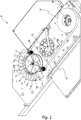
FIGURE 1 provides a schematic illustration of an optical data storage device using an optical storage tape; -
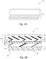
FIGURE 2A is a top view of an optical storage tape surface; -
FIGURE 2B is a cross sectional view of an optical storage tape; -
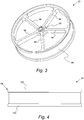
FIGURE 3 is a perspective view of a guiding wheel used in the optical tape storage device; -
FIGURE 4 is a side view of a guiding wheel used in the optical tape storage device; -
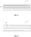
FIGURE 5 is a side view of a guiding wheel having a plurality of grooves; and -
FIGURE 6 is a side view of a guiding wheel having a central groove. - Reference will now be made in detail to presently preferred compositions, embodiments and methods of the present invention, which constitute the best modes of practicing the invention presently known to the inventors. The Figures are not necessarily to scale. However, it is to be understood that the disclosed embodiments are merely exemplary of the invention that may be embodied in various and alternative forms. Therefore, specific details disclosed herein are not to be interpreted as limiting, but merely as a representative basis for any aspect of the invention and/or as a representative basis for teaching one skilled in the art to variously employ the present invention.
- Except in the examples, or where otherwise expressly indicated, all numerical quantities in this description indicating amounts of material or conditions of reaction and/or use are to be understood as modified by the word "about" in describing the broadest scope of the invention. Practice within the numerical limits stated is generally preferred. Also, unless expressly stated to the contrary: the description of a group or class of materials as suitable or preferred for a given purpose in connection with the invention implies that mixtures of any two or more of the members of the group or class are equally suitable or preferred; the first definition of an acronym or other abbreviation applies to all subsequent uses herein of the same abbreviation and applies mutatis mutandis to normal grammatical variations of the initially defined abbreviation; and, unless expressly stated to the contrary, measurement of a property is determined by the same technique as previously or later referenced for the same property.
- It is also to be understood that this invention is not limited to the specific embodiments and methods described below, as specific components and/or conditions may, of course, vary. Furthermore, the terminology used herein is used only for the purpose of describing particular embodiments of the present invention and is not intended to be limiting in any way.
- It must also be noted that, as used in the specification and the appended claims, the singular form "a," "an," and "the" comprise plural referents unless the context clearly indicates otherwise. For example, reference to a component in the singular is intended to comprise a plurality of components.
- With reference to
Figure 1 , a perspective schematic view of an optical data storage device is provided. Opticaldata storage device 10 writes to, reads from, and/or tracksoptical storage tape 12.Optical storage tape 12 includes one or more optical storage layers onto whichdevice 10 encodes digital data. Optical pickup units (OPU) 14 read, write, and/or track data tooptical storage tape 12. Typically, the distance of the OPU from the tape is about 0.1 to 0.8 mm. Afeed reel 16 provides the optical storage tape tooptical pickup units 14.Feed reel 16 is received and held byfeed reel adapter 18.Optical storage device 10 also includes guidingwheel 20 that guides theoptical storage tape 10 when theoptical storage tape 10 is in the vicinity of theoptical pickup units 14 during read and/or write and/or tracking operations. Advantageously, guidingwheel 20 securely holdsoptical storage tape 12 on an curved path (i.e., circular path) during read/write/tracking operations thereby allowing storage densities to approach that of optical disks. Take-up reel 22 receives theoptical storage tape 12 from the guidingwheel 20. Take-up reel 22 is held in place by take-up reel adapter 24 which is driven in a circular direction by electric motor 26. - Still referring to
Figure 1 , opticaldata storage device 10 further optionally includes first guiding post 30 for positioning thestorage tape 12 before contacting guidingwheel 20 and second guiding post 32 for positioningoptical storage tape 12 after disengagingguiding wheel 20. - With reference to
Figures 2A and 2B , schematic illustrations of an optical storage tape used in the storage devices set forth above is provided.Figure 2A is a top view of an optical storage tape surface whileFigure 2B is a cross sectional view of an optical storage tape.Optical storage tape 12 includes a plurality of data tracks 40. Although the storage tape is compatible with virtually any number of data tracks, 200 to 600 data tracks are typical. In a refinement, data tracks 40 are configured in a logical track format across a width of the optical storage tape. - An example of an optical storage tape that may be used in the current embodiment is provided by
U.S. Pat. Pub. Nos. 2011/0318506 and2011/0318534 , the entire disclosures of which are hereby incorporated by reference. It should be appreciated that any number of designs may be used forstorage tape 12, each of which include one or more optical storage layers onto whichdevice 10 encodes digital data.Optical tape 12 includessubstrate base layer 46 having substrate film sides 48, 50. Typically,base layer 46 is formed from polyester or other polymeric materials. Examples of such materials include, but are not limited to, polyethylene terephthalate (PET), polyethylene naphthalate (PEN), aramid, and the like, and combinations thereof.Imprint layer 52 is disposed oversubstrate film side 50.Imprint layer 52 includesimprint layer side 54 andimprint layer side 56 withimprint layer side 54 being more proximate tosubstrate base layer 46. Multilayerdata recording section 58 is disposed overimprint layer 52. Multilayerdata recording section 58 typically includes one or more layers involved in the optical recording of data. Multilayerdata recording section 58 includesmetal layer 60 disposed overimprint layer side 56.Metal layer 60 includesmetal layer side 62 andmetal layer side 64.Metal layer side 62 is more proximate toimprint layer 52 thanmetal layer side 64. Multilayerdata recording section 58 also includesdielectric layer 70 disposed overmetal layer side 64.Dielectric layer 70 includesdielectric layer side 72 anddielectric layer side 74 which is more proximate tometal layer 60. Multilayerdata recording section 58 further includesphase change layer 80 which is disposed overdielectric layer 70.Phase change layer 80 includes phasechange layer side 52 and phasechange layer side 54 which is more proximate tophase change layer 50. In this context,phase change layer 50 is the actual layer onto which data is encoded by optical tape storage system 10 (Figure 1 ). Multilayerdata recording section 58 also includesdielectric layer 90 disposed overmetal layer side 54. - With reference to
Figures 3 and 4 , schematic illustrations of guiding wheels used to guide and stably hold the optical storage tape for read/write/tracking operations in the optical storage device are provided.Figure 3 is a perspective view of a guiding wheel used in the optical tape storage device.Figure 4 is a side view of a guiding wheel used in the optical tape storage device. Guidingwheel 20 includes a circularouter portion 94 that contacts the storage tape.Spokes 96 connect circularouter portion 20 toinner hub 98. Virtually any type of material may be used for the construction of guidingwheel 20. For example, non-magnetic materials such as aluminum, magnesium, titanium, plastics, and metal-coated plastics may be used to construct guidingwheel 20. In a refinement, guidingwheel 20 includes edge guides 100, 102 for holding the optical storage tape in place. - With reference to
Figures 1 ,5 and 6 , schematic designs of guiding wheels having reduced air film formation are provided. During operation of theoptical storage system 10, guidingwheel 20 spins about at a high rate. Drag forces and the viscosity of air combine to form an air film that acts to pushoptical storage tape 12 away from guidingwheel 20. One solution for the formation of such air films is the incorporation of one or more grooves that assist in maintaining contact between the optical storage tape and the guiding wheel by providing a space for air to escape into.Figure 5 provides a variation of guidingwheel 20 which includes a plurality ofgrooves 106 into which air can escape into thereby mitigating the effect of an air film being formed.Figure 6 provides another variation in which guidingwheel 20 includescentral groove 108 into which air can escape thereby reducing the effects of an air film. In other variations, guidingwheel 20 comprises a porous material (e.g. porous metal or polymer) that assists in maintaining contact between the optical storage tape and the guiding wheel by allowing air to escape into or out of the guiding wheel. It should be appreciated that each of these air film solutions can be used singly or in combination. - While embodiments of the invention have been illustrated and described, it is not intended that these embodiments illustrate and describe all possible forms of the invention. Rather, the words used in the specification are words of description rather than limitation, and it is understood that various changes may be made without departing from the scope of the invention which is defined by the appended claims.
Claims (14)
- An optical data storage device (10) comprising:a feed reel adapter (18) configured to hold a feed reel (16) having an optical storage tape (12);a plurality of optical pickup units (14) configured to read and write data to an optical storage tape of a feed reel held by the feed reel adapter;a guiding wheel (20) configured to guide the optical storage tape when the optical storage tape is in the vicinity of the optical pickup units during read and/or write operations, wherein the guiding wheel has a circular outer portion (94) which is configured to hold the optical storage tape on a circular path during read/write/tracking operations, and wherein the plurality of optical pickup units are arranged in an arc circumferentially around the outside of the guiding wheel; anda take-up reel adapter (22) for holding a take-up reel configured to receive the optical storage tape from the guiding wheel.
- The optical data storage device of claim 1, further comprising:an optical storage tape (12) having one or more optical storage layers;a feed reel (16) held by the feed reel adapter and configured to provide the optical storage tape to the optical pickup units; anda take-up reel (22) held by the take-up reel adapter and configured to receive the optical storage tape from the guiding wheel
- The optical data storage device of claim 2 wherein the optical storage tape has a plurality of data tracks (40).
- The optical data storage device of claim 3 wherein the optical storage tape includes from 200 to 600 data tracks.
- The optical data storage device of claim 3 wherein the data tracks are configured in a logical track format across a width of the optical storage tape.
- The optical data storage device of claim 1 wherein the guiding wheel is nonmagnetic.
- The optical data storage device of claim 1 wherein the guiding wheel comprises aluminum, magnesium, titanium, plastics, and metal-coated plastics.
- The optical data storage device of claim 1 or 2 further comprising a first guiding post (30) for positioning the storage tape before contacting the guiding wheel and a second guiding post (32) for positioning the optical storage tape after disengaging the guiding wheel.
- The optical data storage device of claim 1 or 2 wherein the guiding wheel includes one or more grooves (106) that assist in maintaining contact between the optical storage tape and the guiding wheel.
- The optical data storage device of claim 1 or 2 wherein the guiding wheel comprises a porous metal that assists in maintaining contact between the optical storage tape and the guiding wheel.
- The optical data storage device of claim 2 wherein the optical storage tape includes a base layer (46) over which the optical storage layers are disposed.
- The optical data storage tape of claim 11 wherein the base layer includes a component selected from the group consisting of polyethylene terephthalate (PET), polyethylene naphthalate (PEN), aramid, and combinations thereof.
- The optical data storage tape of claim 1 or 2 wherein the guiding wheel includes edge guides (100, 102) for holding the optical storage tape in place.
- A method of storing data on an optical storage tape, the method comprising:providing the optical storage tape to a guiding wheel such that the optical storage tape moves along an arced path when the optical storage tape contacts the guiding wheel;reading or writing data to the optical storage tape by a plurality of optical pickup units positioned about the guiding wheel, wherein the guiding wheel has a circular outer portion which is configured to hold the optical storage tape on a circular path during read/write/tracking operations, and wherein the plurality of optical pickup units are arranged in an arc circumferentially around the outside of the guiding wheel; andreceiving the optical storage tape onto a take-up reel.
Applications Claiming Priority (2)
| Application Number | Priority Date | Filing Date | Title |
|---|---|---|---|
| US13/677,511 US9009745B2 (en) | 2012-11-15 | 2012-11-15 | Thin web optical media guiding method |
| PCT/US2013/068880 WO2014078165A1 (en) | 2012-11-15 | 2013-11-07 | Thin web optical media guiding method |
Publications (2)
| Publication Number | Publication Date |
|---|---|
| EP2920786A1 EP2920786A1 (en) | 2015-09-23 |
| EP2920786B1 true EP2920786B1 (en) | 2019-09-11 |
Family
ID=49627108
Family Applications (1)
| Application Number | Title | Priority Date | Filing Date |
|---|---|---|---|
| EP13795102.6A Active EP2920786B1 (en) | 2012-11-15 | 2013-11-07 | Thin web optical media guiding method |
Country Status (7)
| Country | Link |
|---|---|
| US (1) | US9009745B2 (en) |
| EP (1) | EP2920786B1 (en) |
| JP (1) | JP6329559B2 (en) |
| CN (1) | CN104781881B (en) |
| AU (1) | AU2013345152B2 (en) |
| NZ (1) | NZ706833A (en) |
| WO (1) | WO2014078165A1 (en) |
Families Citing this family (2)
| Publication number | Priority date | Publication date | Assignee | Title |
|---|---|---|---|---|
| US9916852B2 (en) * | 2016-06-15 | 2018-03-13 | Oracle International Corporation | Optical tape with an increased track pitch for improvement of tracking performance after seam |
| CN113474837B (en) * | 2019-03-27 | 2022-07-29 | 富士胶片株式会社 | Export device, export method, storage medium, and magnetic tape |
Family Cites Families (34)
| Publication number | Priority date | Publication date | Assignee | Title |
|---|---|---|---|---|
| US3270933A (en) * | 1963-12-20 | 1966-09-06 | Minnesota Mining & Mfg | Air-cushioned tape guide |
| JPS59112337U (en) * | 1983-01-18 | 1984-07-28 | オタリ株式会社 | tape reel adapter |
| US4514055A (en) | 1983-01-20 | 1985-04-30 | Bell & Howell Company | Information transferring systems operating on a recording medium |
| JPS62228713A (en) * | 1986-03-29 | 1987-10-07 | Kyocera Corp | Air bearing |
| JPS63206942A (en) * | 1987-02-23 | 1988-08-26 | Sony Corp | Optical recording/reproducing device |
| US4970707A (en) | 1987-09-04 | 1990-11-13 | Hitachi, Ltd. | Optical tape apparatus with a tracking control mechanism and/or a focusing control mechanism |
| JPH01303683A (en) * | 1988-05-31 | 1989-12-07 | Matsushita Electric Ind Co Ltd | Manufacture of tape guide and tape cassette using the tape guide |
| JP2808634B2 (en) | 1989-02-17 | 1998-10-08 | ソニー株式会社 | Head drum |
| JPH02287958A (en) * | 1989-04-28 | 1990-11-28 | Matsushita Electric Ind Co Ltd | Recording and reproducing device |
| JPH03171443A (en) * | 1989-11-29 | 1991-07-24 | Sharp Corp | Cassette optical tape |
| JPH03270925A (en) * | 1990-03-20 | 1991-12-03 | Toyoda Gosei Co Ltd | Tape sticking device |
| JP2793410B2 (en) * | 1991-04-22 | 1998-09-03 | インターナショナル・ビジネス・マシーンズ・コーポレイション | Web drive and tape drive |
| KR950014836B1 (en) | 1993-08-24 | 1995-12-15 | 대우전자주식회사 | Recording & reproducting apparatus optical tape |
| CN1067792C (en) * | 1994-12-05 | 2001-06-27 | 皇家菲利浦电子有限公司 | Optical unit for optically scanning and information surface, and optical scanning arrangement including optical unit |
| US5995269A (en) * | 1996-10-09 | 1999-11-30 | U.S. Philips Corporation | Optical unit for optically scanning an information surface, and optical scanning arrangement including the optical unit |
| US6215618B1 (en) * | 1998-11-06 | 2001-04-10 | Hewlett-Packard Co. | Linear tape drive head cleaning process |
| US6336608B1 (en) * | 2000-02-29 | 2002-01-08 | James Robert Cope | Flexible web roller guide assembly with an integral centrifugal pump capability to provide a hydrostatic air bearing function to the roller guides outside supporting surface |
| US6435451B1 (en) * | 2000-10-19 | 2002-08-20 | Storage Technology Corporation | Compliant tape reel flanges |
| US6690639B2 (en) * | 2001-10-19 | 2004-02-10 | Eastman Kodak Company | Optical tape transport system using focus stabilizer |
| JP3918666B2 (en) | 2002-07-17 | 2007-05-23 | ソニー株式会社 | Tape-like optical recording medium driving device |
| US7260884B2 (en) | 2003-04-15 | 2007-08-28 | Athan Corporation | Method of manufacturing a drum assembly associated with video tape machine |
| US6938851B2 (en) * | 2003-04-23 | 2005-09-06 | International Business Machines Corporation | Tape path roller guide and method for making |
| CN2641766Y (en) * | 2003-08-16 | 2004-09-15 | 常州市新科精密机械有限公司 | CD loading device |
| US7173794B2 (en) * | 2003-09-17 | 2007-02-06 | Imation Corp. | Accessing both sides of data storage tape |
| US7369483B2 (en) * | 2004-01-21 | 2008-05-06 | Microcontinuum, Inc. | Pre-formatted linear optical data storage medium |
| US7204445B2 (en) * | 2004-08-05 | 2007-04-17 | Imation Corp. | Guide arrangements for data storage tape guiding systems |
| US7204446B2 (en) * | 2004-08-05 | 2007-04-17 | Imation Corp. | Data storage tape guiding systems using tapered guides |
| US7969832B2 (en) | 2006-02-02 | 2011-06-28 | Oracle America, Inc. | Optical tape drive systems |
| JP2009043392A (en) * | 2007-07-13 | 2009-02-26 | Hitachi Maxell Ltd | Tape device |
| US8488266B2 (en) * | 2008-05-14 | 2013-07-16 | Hewlett-Packard Development Company, L.P. | Adjustment of tape reel height |
| JP4373482B1 (en) * | 2008-08-05 | 2009-11-25 | 日立マクセル株式会社 | Magnetic tape and manufacturing method thereof |
| US8014246B2 (en) * | 2009-12-16 | 2011-09-06 | Oracle America, Inc. | Data storage system and method for calibrating same |
| US20110318534A1 (en) | 2010-06-24 | 2011-12-29 | Oracle International Corporation | Low Viscosity Monomer for Patterning Optical Tape |
| US20110318506A1 (en) | 2010-06-24 | 2011-12-29 | Oracle International Corporation | Optical Tape Media Patterning Using Cationic Polymerizable Monomers |
-
2012
- 2012-11-15 US US13/677,511 patent/US9009745B2/en active Active
-
2013
- 2013-11-07 JP JP2015542704A patent/JP6329559B2/en active Active
- 2013-11-07 EP EP13795102.6A patent/EP2920786B1/en active Active
- 2013-11-07 WO PCT/US2013/068880 patent/WO2014078165A1/en active Application Filing
- 2013-11-07 NZ NZ706833A patent/NZ706833A/en unknown
- 2013-11-07 AU AU2013345152A patent/AU2013345152B2/en active Active
- 2013-11-07 CN CN201380059681.2A patent/CN104781881B/en active Active
Non-Patent Citations (1)
| Title |
|---|
| None * |
Also Published As
| Publication number | Publication date |
|---|---|
| WO2014078165A1 (en) | 2014-05-22 |
| CN104781881B (en) | 2018-04-10 |
| JP6329559B2 (en) | 2018-05-23 |
| US20140137138A1 (en) | 2014-05-15 |
| AU2013345152B2 (en) | 2017-12-21 |
| CN104781881A (en) | 2015-07-15 |
| NZ706833A (en) | 2018-03-23 |
| AU2013345152A1 (en) | 2015-05-14 |
| JP2016501418A (en) | 2016-01-18 |
| EP2920786A1 (en) | 2015-09-23 |
| US9009745B2 (en) | 2015-04-14 |
Similar Documents
| Publication | Publication Date | Title |
|---|---|---|
| CA2553837C (en) | Pre-formatted linear optical data storage medium | |
| US8385162B2 (en) | Shingled-writing thermal assistance recording (TAR) disk drive with avoidance of adjacent track erasure from a wide-area heater | |
| US7369483B2 (en) | Pre-formatted linear optical data storage medium | |
| US11367459B2 (en) | Total dimensional stability compensation system and method for magnetic tape drive | |
| CN110931057B (en) | Data storage cartridge with magnetic head-disk interface (HDI) | |
| JP2006107597A (en) | Magnetic tape recording and reproducing method and device | |
| EP2920786B1 (en) | Thin web optical media guiding method | |
| JP6534413B2 (en) | Rotary head data storage and retrieval system and method for data verification | |
| EP1168323A2 (en) | Irregular surfaced tape guide | |
| US20140126343A1 (en) | Rotary Head Data Storage and Retrieval System and Method for Data Erasure | |
| US6940672B2 (en) | Azimuthal transition layout for two-sided data storage tape | |
| US20150255107A1 (en) | Tape recording medium, information recording/reproducing device, and method of manufacturing tape recording medium | |
| JP5467729B2 (en) | Magnetic tape unit | |
| US20030231428A1 (en) | Magnetic head | |
| JP2774625B2 (en) | Magnetic storage device, magnetic head, and read / write method | |
| US9280997B2 (en) | Tape recording medium having both optical and magnetic recording layers | |
| JPH0524561B2 (en) | ||
| JP2006179122A (en) | Manufacturing method and manufacturing apparatus of thin optical disk | |
| JP2006085857A (en) | Magnetic transfer device, magnetic transfer method, and manufacturing method of magnetic recording medium | |
| JP2008299910A (en) | Write-once information recording medium, information recording apparatus, and information playback apparatus |
Legal Events
| Date | Code | Title | Description |
|---|---|---|---|
| PUAI | Public reference made under article 153(3) epc to a published international application that has entered the european phase |
Free format text: ORIGINAL CODE: 0009012 |
|
| 17P | Request for examination filed |
Effective date: 20150615 |
|
| AK | Designated contracting states |
Kind code of ref document: A1 Designated state(s): AL AT BE BG CH CY CZ DE DK EE ES FI FR GB GR HR HU IE IS IT LI LT LU LV MC MK MT NL NO PL PT RO RS SE SI SK SM TR |
|
| AX | Request for extension of the european patent |
Extension state: BA ME |
|
| DAX | Request for extension of the european patent (deleted) | ||
| GRAP | Despatch of communication of intention to grant a patent |
Free format text: ORIGINAL CODE: EPIDOSNIGR1 |
|
| STAA | Information on the status of an ep patent application or granted ep patent |
Free format text: STATUS: GRANT OF PATENT IS INTENDED |
|
| INTG | Intention to grant announced |
Effective date: 20181030 |
|
| GRAJ | Information related to disapproval of communication of intention to grant by the applicant or resumption of examination proceedings by the epo deleted |
Free format text: ORIGINAL CODE: EPIDOSDIGR1 |
|
| STAA | Information on the status of an ep patent application or granted ep patent |
Free format text: STATUS: REQUEST FOR EXAMINATION WAS MADE |
|
| GRAP | Despatch of communication of intention to grant a patent |
Free format text: ORIGINAL CODE: EPIDOSNIGR1 |
|
| STAA | Information on the status of an ep patent application or granted ep patent |
Free format text: STATUS: GRANT OF PATENT IS INTENDED |
|
| INTC | Intention to grant announced (deleted) | ||
| INTG | Intention to grant announced |
Effective date: 20190405 |
|
| GRAS | Grant fee paid |
Free format text: ORIGINAL CODE: EPIDOSNIGR3 |
|
| GRAA | (expected) grant |
Free format text: ORIGINAL CODE: 0009210 |
|
| STAA | Information on the status of an ep patent application or granted ep patent |
Free format text: STATUS: THE PATENT HAS BEEN GRANTED |
|
| AK | Designated contracting states |
Kind code of ref document: B1 Designated state(s): AL AT BE BG CH CY CZ DE DK EE ES FI FR GB GR HR HU IE IS IT LI LT LU LV MC MK MT NL NO PL PT RO RS SE SI SK SM TR |
|
| REG | Reference to a national code |
Ref country code: GB Ref legal event code: FG4D |
|
| REG | Reference to a national code |
Ref country code: CH Ref legal event code: EP |
|
| REG | Reference to a national code |
Ref country code: AT Ref legal event code: REF Ref document number: 1179512 Country of ref document: AT Kind code of ref document: T Effective date: 20190915 |
|
| REG | Reference to a national code |
Ref country code: DE Ref legal event code: R096 Ref document number: 602013060430 Country of ref document: DE Ref country code: IE Ref legal event code: FG4D |
|
| REG | Reference to a national code |
Ref country code: NL Ref legal event code: MP Effective date: 20190911 |
|
| REG | Reference to a national code |
Ref country code: LT Ref legal event code: MG4D |
|
| PG25 | Lapsed in a contracting state [announced via postgrant information from national office to epo] |
Ref country code: SE Free format text: LAPSE BECAUSE OF FAILURE TO SUBMIT A TRANSLATION OF THE DESCRIPTION OR TO PAY THE FEE WITHIN THE PRESCRIBED TIME-LIMIT Effective date: 20190911 Ref country code: HR Free format text: LAPSE BECAUSE OF FAILURE TO SUBMIT A TRANSLATION OF THE DESCRIPTION OR TO PAY THE FEE WITHIN THE PRESCRIBED TIME-LIMIT Effective date: 20190911 Ref country code: LT Free format text: LAPSE BECAUSE OF FAILURE TO SUBMIT A TRANSLATION OF THE DESCRIPTION OR TO PAY THE FEE WITHIN THE PRESCRIBED TIME-LIMIT Effective date: 20190911 Ref country code: FI Free format text: LAPSE BECAUSE OF FAILURE TO SUBMIT A TRANSLATION OF THE DESCRIPTION OR TO PAY THE FEE WITHIN THE PRESCRIBED TIME-LIMIT Effective date: 20190911 Ref country code: BG Free format text: LAPSE BECAUSE OF FAILURE TO SUBMIT A TRANSLATION OF THE DESCRIPTION OR TO PAY THE FEE WITHIN THE PRESCRIBED TIME-LIMIT Effective date: 20191211 Ref country code: NO Free format text: LAPSE BECAUSE OF FAILURE TO SUBMIT A TRANSLATION OF THE DESCRIPTION OR TO PAY THE FEE WITHIN THE PRESCRIBED TIME-LIMIT Effective date: 20191211 |
|
| PG25 | Lapsed in a contracting state [announced via postgrant information from national office to epo] |
Ref country code: AL Free format text: LAPSE BECAUSE OF FAILURE TO SUBMIT A TRANSLATION OF THE DESCRIPTION OR TO PAY THE FEE WITHIN THE PRESCRIBED TIME-LIMIT Effective date: 20190911 Ref country code: ES Free format text: LAPSE BECAUSE OF FAILURE TO SUBMIT A TRANSLATION OF THE DESCRIPTION OR TO PAY THE FEE WITHIN THE PRESCRIBED TIME-LIMIT Effective date: 20190911 Ref country code: LV Free format text: LAPSE BECAUSE OF FAILURE TO SUBMIT A TRANSLATION OF THE DESCRIPTION OR TO PAY THE FEE WITHIN THE PRESCRIBED TIME-LIMIT Effective date: 20190911 Ref country code: RS Free format text: LAPSE BECAUSE OF FAILURE TO SUBMIT A TRANSLATION OF THE DESCRIPTION OR TO PAY THE FEE WITHIN THE PRESCRIBED TIME-LIMIT Effective date: 20190911 Ref country code: GR Free format text: LAPSE BECAUSE OF FAILURE TO SUBMIT A TRANSLATION OF THE DESCRIPTION OR TO PAY THE FEE WITHIN THE PRESCRIBED TIME-LIMIT Effective date: 20191212 |
|
| REG | Reference to a national code |
Ref country code: AT Ref legal event code: MK05 Ref document number: 1179512 Country of ref document: AT Kind code of ref document: T Effective date: 20190911 |
|
| PG25 | Lapsed in a contracting state [announced via postgrant information from national office to epo] |
Ref country code: IT Free format text: LAPSE BECAUSE OF FAILURE TO SUBMIT A TRANSLATION OF THE DESCRIPTION OR TO PAY THE FEE WITHIN THE PRESCRIBED TIME-LIMIT Effective date: 20190911 Ref country code: PT Free format text: LAPSE BECAUSE OF FAILURE TO SUBMIT A TRANSLATION OF THE DESCRIPTION OR TO PAY THE FEE WITHIN THE PRESCRIBED TIME-LIMIT Effective date: 20200113 Ref country code: NL Free format text: LAPSE BECAUSE OF FAILURE TO SUBMIT A TRANSLATION OF THE DESCRIPTION OR TO PAY THE FEE WITHIN THE PRESCRIBED TIME-LIMIT Effective date: 20190911 Ref country code: RO Free format text: LAPSE BECAUSE OF FAILURE TO SUBMIT A TRANSLATION OF THE DESCRIPTION OR TO PAY THE FEE WITHIN THE PRESCRIBED TIME-LIMIT Effective date: 20190911 Ref country code: EE Free format text: LAPSE BECAUSE OF FAILURE TO SUBMIT A TRANSLATION OF THE DESCRIPTION OR TO PAY THE FEE WITHIN THE PRESCRIBED TIME-LIMIT Effective date: 20190911 Ref country code: AT Free format text: LAPSE BECAUSE OF FAILURE TO SUBMIT A TRANSLATION OF THE DESCRIPTION OR TO PAY THE FEE WITHIN THE PRESCRIBED TIME-LIMIT Effective date: 20190911 Ref country code: PL Free format text: LAPSE BECAUSE OF FAILURE TO SUBMIT A TRANSLATION OF THE DESCRIPTION OR TO PAY THE FEE WITHIN THE PRESCRIBED TIME-LIMIT Effective date: 20190911 |
|
| PG25 | Lapsed in a contracting state [announced via postgrant information from national office to epo] |
Ref country code: IS Free format text: LAPSE BECAUSE OF FAILURE TO SUBMIT A TRANSLATION OF THE DESCRIPTION OR TO PAY THE FEE WITHIN THE PRESCRIBED TIME-LIMIT Effective date: 20200224 Ref country code: SM Free format text: LAPSE BECAUSE OF FAILURE TO SUBMIT A TRANSLATION OF THE DESCRIPTION OR TO PAY THE FEE WITHIN THE PRESCRIBED TIME-LIMIT Effective date: 20190911 Ref country code: SK Free format text: LAPSE BECAUSE OF FAILURE TO SUBMIT A TRANSLATION OF THE DESCRIPTION OR TO PAY THE FEE WITHIN THE PRESCRIBED TIME-LIMIT Effective date: 20190911 Ref country code: CZ Free format text: LAPSE BECAUSE OF FAILURE TO SUBMIT A TRANSLATION OF THE DESCRIPTION OR TO PAY THE FEE WITHIN THE PRESCRIBED TIME-LIMIT Effective date: 20190911 |
|
| REG | Reference to a national code |
Ref country code: DE Ref legal event code: R097 Ref document number: 602013060430 Country of ref document: DE |
|
| REG | Reference to a national code |
Ref country code: CH Ref legal event code: PL |
|
| PLBE | No opposition filed within time limit |
Free format text: ORIGINAL CODE: 0009261 |
|
| STAA | Information on the status of an ep patent application or granted ep patent |
Free format text: STATUS: NO OPPOSITION FILED WITHIN TIME LIMIT |
|
| PG2D | Information on lapse in contracting state deleted |
Ref country code: IS |
|
| PG25 | Lapsed in a contracting state [announced via postgrant information from national office to epo] |
Ref country code: LI Free format text: LAPSE BECAUSE OF NON-PAYMENT OF DUE FEES Effective date: 20191130 Ref country code: DK Free format text: LAPSE BECAUSE OF FAILURE TO SUBMIT A TRANSLATION OF THE DESCRIPTION OR TO PAY THE FEE WITHIN THE PRESCRIBED TIME-LIMIT Effective date: 20190911 Ref country code: MC Free format text: LAPSE BECAUSE OF FAILURE TO SUBMIT A TRANSLATION OF THE DESCRIPTION OR TO PAY THE FEE WITHIN THE PRESCRIBED TIME-LIMIT Effective date: 20190911 Ref country code: LU Free format text: LAPSE BECAUSE OF NON-PAYMENT OF DUE FEES Effective date: 20191107 Ref country code: CH Free format text: LAPSE BECAUSE OF NON-PAYMENT OF DUE FEES Effective date: 20191130 Ref country code: IS Free format text: LAPSE BECAUSE OF FAILURE TO SUBMIT A TRANSLATION OF THE DESCRIPTION OR TO PAY THE FEE WITHIN THE PRESCRIBED TIME-LIMIT Effective date: 20200112 |
|
| 26N | No opposition filed |
Effective date: 20200615 |
|
| REG | Reference to a national code |
Ref country code: BE Ref legal event code: MM Effective date: 20191130 |
|
| PG25 | Lapsed in a contracting state [announced via postgrant information from national office to epo] |
Ref country code: SI Free format text: LAPSE BECAUSE OF FAILURE TO SUBMIT A TRANSLATION OF THE DESCRIPTION OR TO PAY THE FEE WITHIN THE PRESCRIBED TIME-LIMIT Effective date: 20190911 |
|
| PG25 | Lapsed in a contracting state [announced via postgrant information from national office to epo] |
Ref country code: FR Free format text: LAPSE BECAUSE OF NON-PAYMENT OF DUE FEES Effective date: 20191111 Ref country code: IE Free format text: LAPSE BECAUSE OF NON-PAYMENT OF DUE FEES Effective date: 20191107 |
|
| PG25 | Lapsed in a contracting state [announced via postgrant information from national office to epo] |
Ref country code: BE Free format text: LAPSE BECAUSE OF NON-PAYMENT OF DUE FEES Effective date: 20191130 |
|
| PG25 | Lapsed in a contracting state [announced via postgrant information from national office to epo] |
Ref country code: CY Free format text: LAPSE BECAUSE OF FAILURE TO SUBMIT A TRANSLATION OF THE DESCRIPTION OR TO PAY THE FEE WITHIN THE PRESCRIBED TIME-LIMIT Effective date: 20190911 |
|
| PG25 | Lapsed in a contracting state [announced via postgrant information from national office to epo] |
Ref country code: MT Free format text: LAPSE BECAUSE OF FAILURE TO SUBMIT A TRANSLATION OF THE DESCRIPTION OR TO PAY THE FEE WITHIN THE PRESCRIBED TIME-LIMIT Effective date: 20190911 Ref country code: HU Free format text: LAPSE BECAUSE OF FAILURE TO SUBMIT A TRANSLATION OF THE DESCRIPTION OR TO PAY THE FEE WITHIN THE PRESCRIBED TIME-LIMIT; INVALID AB INITIO Effective date: 20131107 |
|
| PG25 | Lapsed in a contracting state [announced via postgrant information from national office to epo] |
Ref country code: TR Free format text: LAPSE BECAUSE OF FAILURE TO SUBMIT A TRANSLATION OF THE DESCRIPTION OR TO PAY THE FEE WITHIN THE PRESCRIBED TIME-LIMIT Effective date: 20190911 |
|
| PG25 | Lapsed in a contracting state [announced via postgrant information from national office to epo] |
Ref country code: MK Free format text: LAPSE BECAUSE OF FAILURE TO SUBMIT A TRANSLATION OF THE DESCRIPTION OR TO PAY THE FEE WITHIN THE PRESCRIBED TIME-LIMIT Effective date: 20190911 |
|
| P01 | Opt-out of the competence of the unified patent court (upc) registered |
Effective date: 20230522 |
|
| PGFP | Annual fee paid to national office [announced via postgrant information from national office to epo] |
Ref country code: GB Payment date: 20231006 Year of fee payment: 11 |
|
| PGFP | Annual fee paid to national office [announced via postgrant information from national office to epo] |
Ref country code: DE Payment date: 20230929 Year of fee payment: 11 |