EP2920450B1 - Gas mixer for internal combustion engine - Google Patents
Gas mixer for internal combustion engine Download PDFInfo
- Publication number
- EP2920450B1 EP2920450B1 EP12780095.1A EP12780095A EP2920450B1 EP 2920450 B1 EP2920450 B1 EP 2920450B1 EP 12780095 A EP12780095 A EP 12780095A EP 2920450 B1 EP2920450 B1 EP 2920450B1
- Authority
- EP
- European Patent Office
- Prior art keywords
- gaseous fuel
- displacement body
- gas mixer
- longitudinal axis
- air
- Prior art date
- Legal status (The legal status is an assumption and is not a legal conclusion. Google has not performed a legal analysis and makes no representation as to the accuracy of the status listed.)
- Active
Links
Images




Classifications
-
- F—MECHANICAL ENGINEERING; LIGHTING; HEATING; WEAPONS; BLASTING
- F02—COMBUSTION ENGINES; HOT-GAS OR COMBUSTION-PRODUCT ENGINE PLANTS
- F02M—SUPPLYING COMBUSTION ENGINES IN GENERAL WITH COMBUSTIBLE MIXTURES OR CONSTITUENTS THEREOF
- F02M21/00—Apparatus for supplying engines with non-liquid fuels, e.g. gaseous fuels stored in liquid form
- F02M21/02—Apparatus for supplying engines with non-liquid fuels, e.g. gaseous fuels stored in liquid form for gaseous fuels
- F02M21/0218—Details on the gaseous fuel supply system, e.g. tanks, valves, pipes, pumps, rails, injectors or mixers
- F02M21/023—Valves; Pressure or flow regulators in the fuel supply or return system
- F02M21/0236—Multi-way valves; Multiple valves forming a multi-way valve system
-
- F—MECHANICAL ENGINEERING; LIGHTING; HEATING; WEAPONS; BLASTING
- F02—COMBUSTION ENGINES; HOT-GAS OR COMBUSTION-PRODUCT ENGINE PLANTS
- F02D—CONTROLLING COMBUSTION ENGINES
- F02D9/00—Controlling engines by throttling air or fuel-and-air induction conduits or exhaust conduits
- F02D9/02—Controlling engines by throttling air or fuel-and-air induction conduits or exhaust conduits concerning induction conduits
-
- F—MECHANICAL ENGINEERING; LIGHTING; HEATING; WEAPONS; BLASTING
- F02—COMBUSTION ENGINES; HOT-GAS OR COMBUSTION-PRODUCT ENGINE PLANTS
- F02M—SUPPLYING COMBUSTION ENGINES IN GENERAL WITH COMBUSTIBLE MIXTURES OR CONSTITUENTS THEREOF
- F02M21/00—Apparatus for supplying engines with non-liquid fuels, e.g. gaseous fuels stored in liquid form
- F02M21/02—Apparatus for supplying engines with non-liquid fuels, e.g. gaseous fuels stored in liquid form for gaseous fuels
- F02M21/0218—Details on the gaseous fuel supply system, e.g. tanks, valves, pipes, pumps, rails, injectors or mixers
- F02M21/023—Valves; Pressure or flow regulators in the fuel supply or return system
- F02M21/0242—Shut-off valves; Check valves; Safety valves; Pressure relief valves
-
- F—MECHANICAL ENGINEERING; LIGHTING; HEATING; WEAPONS; BLASTING
- F02—COMBUSTION ENGINES; HOT-GAS OR COMBUSTION-PRODUCT ENGINE PLANTS
- F02M—SUPPLYING COMBUSTION ENGINES IN GENERAL WITH COMBUSTIBLE MIXTURES OR CONSTITUENTS THEREOF
- F02M21/00—Apparatus for supplying engines with non-liquid fuels, e.g. gaseous fuels stored in liquid form
- F02M21/02—Apparatus for supplying engines with non-liquid fuels, e.g. gaseous fuels stored in liquid form for gaseous fuels
- F02M21/04—Gas-air mixing apparatus
- F02M21/042—Mixer comprising a plurality of bores or flow passages
-
- F—MECHANICAL ENGINEERING; LIGHTING; HEATING; WEAPONS; BLASTING
- F16—ENGINEERING ELEMENTS AND UNITS; GENERAL MEASURES FOR PRODUCING AND MAINTAINING EFFECTIVE FUNCTIONING OF MACHINES OR INSTALLATIONS; THERMAL INSULATION IN GENERAL
- F16K—VALVES; TAPS; COCKS; ACTUATING-FLOATS; DEVICES FOR VENTING OR AERATING
- F16K11/00—Multiple-way valves, e.g. mixing valves; Pipe fittings incorporating such valves
- F16K11/02—Multiple-way valves, e.g. mixing valves; Pipe fittings incorporating such valves with all movable sealing faces moving as one unit
- F16K11/06—Multiple-way valves, e.g. mixing valves; Pipe fittings incorporating such valves with all movable sealing faces moving as one unit comprising only sliding valves, i.e. sliding closure elements
- F16K11/072—Multiple-way valves, e.g. mixing valves; Pipe fittings incorporating such valves with all movable sealing faces moving as one unit comprising only sliding valves, i.e. sliding closure elements with pivoted closure members
-
- F—MECHANICAL ENGINEERING; LIGHTING; HEATING; WEAPONS; BLASTING
- F16—ENGINEERING ELEMENTS AND UNITS; GENERAL MEASURES FOR PRODUCING AND MAINTAINING EFFECTIVE FUNCTIONING OF MACHINES OR INSTALLATIONS; THERMAL INSULATION IN GENERAL
- F16K—VALVES; TAPS; COCKS; ACTUATING-FLOATS; DEVICES FOR VENTING OR AERATING
- F16K11/00—Multiple-way valves, e.g. mixing valves; Pipe fittings incorporating such valves
- F16K11/02—Multiple-way valves, e.g. mixing valves; Pipe fittings incorporating such valves with all movable sealing faces moving as one unit
- F16K11/08—Multiple-way valves, e.g. mixing valves; Pipe fittings incorporating such valves with all movable sealing faces moving as one unit comprising only taps or cocks
- F16K11/085—Multiple-way valves, e.g. mixing valves; Pipe fittings incorporating such valves with all movable sealing faces moving as one unit comprising only taps or cocks with cylindrical plug
-
- F—MECHANICAL ENGINEERING; LIGHTING; HEATING; WEAPONS; BLASTING
- F02—COMBUSTION ENGINES; HOT-GAS OR COMBUSTION-PRODUCT ENGINE PLANTS
- F02M—SUPPLYING COMBUSTION ENGINES IN GENERAL WITH COMBUSTIBLE MIXTURES OR CONSTITUENTS THEREOF
- F02M26/00—Engine-pertinent apparatus for adding exhaust gases to combustion-air, main fuel or fuel-air mixture, e.g. by exhaust gas recirculation [EGR] systems
- F02M26/13—Arrangement or layout of EGR passages, e.g. in relation to specific engine parts or for incorporation of accessories
- F02M26/17—Arrangement or layout of EGR passages, e.g. in relation to specific engine parts or for incorporation of accessories in relation to the intake system
- F02M26/19—Means for improving the mixing of air and recirculated exhaust gases, e.g. venturis or multiple openings to the intake system
-
- Y—GENERAL TAGGING OF NEW TECHNOLOGICAL DEVELOPMENTS; GENERAL TAGGING OF CROSS-SECTIONAL TECHNOLOGIES SPANNING OVER SEVERAL SECTIONS OF THE IPC; TECHNICAL SUBJECTS COVERED BY FORMER USPC CROSS-REFERENCE ART COLLECTIONS [XRACs] AND DIGESTS
- Y02—TECHNOLOGIES OR APPLICATIONS FOR MITIGATION OR ADAPTATION AGAINST CLIMATE CHANGE
- Y02T—CLIMATE CHANGE MITIGATION TECHNOLOGIES RELATED TO TRANSPORTATION
- Y02T10/00—Road transport of goods or passengers
- Y02T10/10—Internal combustion engine [ICE] based vehicles
- Y02T10/30—Use of alternative fuels, e.g. biofuels
Definitions
- the present disclosure generally refers to gas mixers for internal combustion engines, and more particularly to gas mixers for gaseous fuel internal combustion engines for mixing gaseous fuel and air.
- Gaseous fuel internal combustion engines are internal combustion engines running on gaseous fuel such as propane, natural gas, landfill gas, coal gas, and biogas.
- Gas mixers are fluidly connected to a combustion unit of the gaseous fuel internal combustion engine to supply a mixture of gaseous fuel and air for firing. Gas mixers are used for mixing gaseous fuel and air having a desired air fuel ratio (AFR) such that the gaseous fuel internal combustion engine is operated in a desired operating range.
- AFR air fuel ratio
- DE 41 37 573 A1 discloses a venturi mixer to mix gas and air in combustion engines.
- the venturi mixer may have a central pipe with a venturi shaped profile. Gaseous fuel may enter the central pipe through a circumferential slot close to the venturi constriction.
- a cylindrically symmetric displacement body may be repositioned axially and may have a conical cross-section. Axial displacement of the displacement body may result in an adjustment of an air flow and/or a gaseous fuel flow within a predetermined range of possible AFRs.
- gas mixers have to provide various AFRs.
- a gaseous fuel internal combustion engine which runs on propane having a high calorific value of 93 MJ/m 3 under standard reference conditions may be supplied with air fuel mixture having an AFR being lower than an AFR of an air fuel mixture supplied to a gaseous fuel internal combustion engine which runs on lean gas having a calorific value below 8.5 MJ/m 3 under standard reference conditions.
- a displacement body within the gas mixer may have to be changed if the desired AFR exceeds the predetermined range of possible AFRs.
- the present disclosure is directed, at least in part, to improving or overcoming one or more aspects of prior systems.
- a gas mixer for a gaseous fuel internal combustion engine for mixing gaseous fuel and air may comprise a guiding channel extending along a central longitudinal axis between an inlet for air inlet and an outlet for air fuel mixture, the guiding channel comprising an inner channel wall being n-fold rational symmetric around the central longitudinal axis, except for the presence of the gaseous fuel supply opening.
- the gas mixer may further comprise a displacement body comprising a gaseous fuel inlet and gaseous fuel outlets and arranged within the guiding channel, the displacement body being n-fold rotational symmetric and rotationally displaceable around the central longitudinal axis, except for the presence of the gaseous fuel inlet.
- n is an integer greater than 1.
- the displacement body and the inner channel wall define an air passage therebetween, the air passage having a cross section area in a plane perpendicular to the central longitudinal axis, and a rotational displacement of the displacement body varies the cross section area of the air passage.
- a gaseous fuel internal combustion engine may comprise an air inlet for supplying intake air; a fuel source for supplying gaseous fuel, and a gas mixer as exemplary disclosed herein.
- the gas mixer may be fluidly connected to the air inlet and the fuel source, and may be configured to provide a mixture of gaseous fuel and air having a predetermined air fuel ratio.
- a gas mixer including a cylindrically asymmetric inner channel wall of a guiding channel and a cylindrically asymmetric displacement body arranged in the guiding channel may facilitate adjustment of air flow and gaseous fuel flow over a wide range to adjust an AFR over a wide range. That is, the same displacement body may be used for numerous gaseous fuel types having different specific calorific values and requiring the gaseous fuel internal combustion engine to operate with different AFRs.
- a gas mixer including a cylindrically asymmetric inner channel wall of a guiding channel and a cylindrically asymmetric displacement body arranged in the guiding channel may facilitate a synchronous adjustment of air flow and gaseous fuel flow by utilization of a sole adjusting unit. Furthermore, when using a sole adjusting unit, a displacement of the displacement body causes a direct adjustment of both air flow and gaseous fuel flow by utilization of a sole displaceable member, namely the displacement body.
- a gas mixer including a cylindrically asymmetric inner channel wall of a guiding channel and a cylindrically asymmetric displacement body arranged in the guiding channel may facilitate adjustment of a cross section area of an air passage during operation of a gaseous fuel internal combustion engine to minimize a pressure drop across the air passage.
- Gaseous fuel internal combustion engine 1 may include features not shown, such as fuel systems, air systems, cooling systems, peripheries, drivetrain components, etc.
- gaseous fuel internal combustion engine 1 is considered as a four-stroke gaseous fuel internal combustion engine.
- gaseous fuel internal combustion engine 1 may be any type of engine (e.g., turbine, dual fuel, gaseous fuel, etc.) that would utilize a gas mixer.
- gaseous fuel internal combustion engine 1 may be of any size, with any number of cylinders, and in any configuration (e.g., "V,” in-line, radial, etc.). Gaseous fuel internal combustion engine 1 may be used to power any machine or other device, including locomotive applications, on-highway trucks or vehicles, off-highway trucks or machines, earth moving equipment, generators, aerospace applications, marine applications, offshore applications, pumps, stationary equipment, or other engine powered applications.
- gaseous fuel internal combustion engine 1 is suited to essentially any application wherein an internal combustion power source is desired, and is particularly well suited to applications wherein it is desirable to limit emissions of certain pollutants, such as NO x compounds.
- Gaseous fuel internal combustion engine 1 comprises an engine block 2, at least one cylinder 4 providing at least one combustion chamber 6 for combusting fuel, a piston 8, and a crank-shaft 10 connected to the piston 8 via a piston rod 12. Piston 8 is configured to reciprocate within the cylinder 4.
- Gaseous fuel internal combustion engine 1 further comprises an air - fuel supply system 14 comprising a fuel source 16, an air inlet 18, a gas mixer 20, an intake manifold 22, an intake valve 24, and an intake pathway 26.
- the intake valve 24 is fluidly connected to combustion chamber 6.
- Intake valve 24 is configured to enable injection of compressed charge air and/or a mixture of compressed charge air and gaseous fuel into combustion chamber 6.
- the exhaust gas is released out of the combustion chamber 6 via an outlet valve 28 into an exhaust gas outlet pathway 30, which may fluidly connect to an associated exhaust gas system 32 for treating the exhaust gas, for example, a catalyst reducing pollutant emissions.
- Outlet valve 28 is also fluidly connected to combustion chamber 6.
- Gaseous fuel internal combustion engine 1 may also be a direct or port injection engine, or may include a pre-combustion chamber. Gaseous fuel internal combustion engine 1 may further include an exhaust gas recirculation system that may be operable to recirculate exhaust gas.
- each cylinder 4 of gaseous fuel internal combustion engine 1 is equipped with a spark plug 34.
- a gas mixer 20 is provided and preferably disposed upstream intake manifold 22 that supplies a combustion mixture to engine block 2 and associated cylinder 4.
- gas mixer 20 is configured to provide a mixture of gaseous fuel and air having a predetermined AFR.
- Gas mixer 20 may communicate with an electronic control module via a communication line, which in turn provides electronic signals to gas mixer 20 to control, for example, the AFR.
- the electronic control module may be further configured to control the overall operation of the gaseous fuel internal combustion engine 1.
- the electronic control module may be further connected to various sensors to measure parameters such as combustion mixture pressure/temperature, combustion peak pressure, exhaust gas temperature/pressure sensors, and lambda.
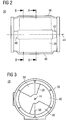
- FIG. 2 an exemplary gas mixer 20 as shown in Fig. 1 is described in greater detail.
- Gas mixer 20 comprises a housing 36, a displacement body 38, and a guiding channel 48.
- Displacement body 38 is arranged within housing 36 in guiding channel 48 as indicated by dashed lines in Fig. 2 . Displacement body 38 is rotationally displaceable around a central longitudinal axis 44. As will be described in greater detail later on, displacement body 38 is cylindrically asymmetric around central longitudinal axis 44.
- gas mixer 20 of Fig. 2 is shown in a front view.
- Housing 36 comprises a front plate 46 having two recesses for guiding air into housing 36.
- Displacement body 38 is disposed downstream of front plate 46.
- two curved faces of displacement body 38 can be seen.
- front plate 46 may have a different quantity of recesses depending on the number of projection sections of displacement body 38 as is described in greater detail later on. For example, a front plate 46 may have one recess if displacement body 38 comprises one projection section, whereas a front plate 46 may have three recesses if displacement body 38 comprises three projection sections.
- housing 36 is described with reference to Figs. 4 and 5 .
- Displacement body 38 is described with reference to Figs. 6 to 9 .
- Gas mixer 20 comprising both housing 36 and displacement body 38 is described with reference to Figs. 10 to 11 .
- Fig. 4 is a sectional view of housing 36, wherein cutting plane line A-A in Fig. 2 indicates the location of the section cut.
- Fig. 5 is a sectional view of housing 36, wherein cutting plane line C-C in Fig. 4 indicates the location of the section cut. It is noted that in both Fig. 4 and 5 for purposes of clarity, displacement body 38 is not shown.
- Housing,36 comprises guiding channel 48.
- Guiding channel 48 extends along central longitudinal axis 44 between an inlet 50 for intake air and an outlet 52 for air fuel mixture.
- Guiding channel 48 includes an inner channel wall 54.
- Inner channel wall 54 is cylindrically asymmetric around central longitudinal axis 44. In other words, inner channel wall 54 is not circular symmetric in the shown sectional view of Fig. 4 . Instead, in the shown embodiment, inner channel wall 54 is 2-fold rotational symmetric, except the presence of gaseous fuel supply opening 60
- Guiding channel 48 comprises a first projection 56 and a second projection 58.
- First and second projection 56, 58 extend parallel to central longitudinal axis 44 and radially inward directed to central longitudinal axis 44.
- Both first and second projection 56, 58 have a ring segment shaped cross section area in a plane perpendicular to central longitudinal axis 44.
- Outer walls of first and second projection 56, 58 define a section of inner channel wall 54. That is, first and second projection 56, 58 result in aforementioned cylindrical asymmetry of inner channel wall 54 around central longitudinal axis 44.
- guiding channel 48 may comprise another number of projections compared to the previously described guiding channel 48.
- Guiding channel 48 may comprise n projections from a range between 1 to n.
- Inner channel wall 54 of guiding channel 48 may be n-fold rotational symmetric around central longitudinal axis 44.
- Housing 36 further comprises a gaseous fuel supply opening 60 disposed in projection 56.
- Gaseous fuel supply opening 60 is arranged parallel to central longitudinal axis 44 and has an elongate shape. Specifically, gaseous fuel supply opening 60 has a rectangular shape. Alternatively, gaseous fuel supply opening 60 may, for example, have an elliptic shape.
- Gaseous fuel supply opening 60 is part of a first section of gaseous fuel passage 62.
- First section of gaseous fuel passage 62 is fluidly connected to fuel source 16 (see Fig. 1 ) via gaseous fuel inlet 61 in housing 36.
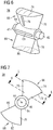
- Fig. 6 is an isometric view of displacement body 38.
- Fig. 7 is a front view of displacement body 38.
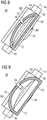
- Fig. 8 is a sectional view of displacement body 38, wherein cutting plane line K-K in Fig. 7 indicates the location of the section cut.
- Fig. 9 is a sectional view of displacement body 38, wherein cutting plane line L-L in Fig. 7 indicates the location of the section cut.
- Displacement body 38 comprises front end 40, back end 42, a central section 64, a projection section 66, and a projection section 68. Displacement body 38 is cylindrically asymmetric around central longitudinal axis 44. Due to projection section 66 and projection section 68 being opposed to projection section 66, displacement body 38 is 2-fold rotational symmetric, except the presence of gaseous fuel inlet 69.
- Front end 40 and back end 42 are connected to central section 64, both front and back end 40, 42 are cylindrically shaped and adapted receive radial bearings (not shown) to enable rotational displacement of displacement body 38.
- Radial bearings may be housed in an annular structure being connected to housing 36 via starlike bars.
- Central section 64 is substantially cylindrically shaped. That is, central section 64 has an annularly shaped cross section area perpendicular to central longitudinal axis 44.
- a gaseous fuel inlet 69 is disposed in the outer circumference of central section 64 providing a passage into displacement body 38. Gaseous fuel inlet 69 is adapted to overlap gaseous fuel supply opening 60 in dependence of a rotational displacement of the displacement body 38 to vary a cross section area of the passage into displacement body 38.
- Gaseous fuel inlet 69 has an elongate shape in a direction parallel to central longitudinal axis 44. Specifically, gaseous fuel inlet 69 has a rectangular shape. Alternatively, gaseous fuel inlet 69 may, for example, have an elliptic shape.
- Projection section 66 comprises a curved face 70, a flat face 72, an outer face 74, and a gaseous fuel outlet 76. Projection section 66 extends from central section 64 in a radial direction away from central longitudinal axis 44.
- Outer face 74 has a shape adapted to a shape of an opposing section of inner channel wall 54 of guiding channel 48.
- Curved face 70 is a free formed surface adapted to provide a venturi constriction together with an opposing section of inner channel wall 54.
- the venturi constriction is formed as a so-called "half venturi" shaped profile.
- the opposing section of inner channel wall 54 may be also a free formed surface adapted to provide a venturi constriction together with curved face 70.
- Gaseous fuel outlet 76 is disposed in curved face 70, and has an elongated shape in a direction perpendicular to central longitudinal axis 44. Specifically, the position of gaseous fuel outlet 76 is downstream (referring to the direction of the air flow) the venturi constriction. Further, gaseous fuel outlet 76 is rectangular shaped. Alternatively, gaseous fuel outlet 76 may be, for example, elliptical shaped.
- gaseous fuel outlet 76 is fluidly connected to gaseous fuel inlet 69.
- displacement body 38 is at least partially hollow to fluidly interconnect gaseous fuel outlet 76 with gaseous fuel inlet 69.
- displacement body 38 may comprise an inner gaseous fuel channel fluidly interconnecting gaseous fuel outlet 76 with gaseous fuel inlet 69.
- displacement body 38 is 2-fold rotational symmetric
- projection section 68 is similar to projection section 66. That is, projection section 68 comprises corresponding curved face 78, flat face 80, outer face 82, and gaseous fuel outlet 84.
- displacement body 38 may comprise another number of projection sections compared to the above described exemplary displacement body 38.
- Displacement body 38 may comprise n projection sections from a range between 1 to n.
- displacement body 38 may be n-fold rotational symmetric around central longitudinal axis 44.
- displacement body 38 may be not discrete rotationally symmetric around central longitudinal axis 44.
- a projection section may comprise more than one gaseous fuel outlet.
- Fig. 10 is a sectional view of gas mixer 20, wherein cutting plane line A-A in Fig. 2 indicates the location of the section cut. Compared to Fig. 4 , displacement body 38 is shown in Fig. 10.
- Fig. 11 is a sectional view of gas mixer 20, wherein cutting plane line B-B in Fig. 2 indicates the location of the section cut.
- Displacement body 38 and inner channel wall 54 define an air passage 86 therebetween. Specifically, curved faces 70, 78 partially border air passage 86. Air passage 86 has a cross section area in a plane perpendicular to central longitudinal axis 44. A rotational displacement of displacement body 38 varies the cross section area of air passage 86.
- Gaseous fuel inlet 69, gaseous fuel outlets 76, 84, and the fluid connection therebetween together form a second section of gaseous fuel passage 62.
- first and second section of gaseous fuel passage 62 are fluidly connected via an overlap of gaseous fuel supply opening 60 in guiding channel 48 and gaseous fuel inlet 69 in displacement body 38. That is, the overlap of gaseous fuel supply opening 60 and gaseous fuel inlet 69 defines a cross section area of gaseous fuel passage 62 passing through gaseous fuel supply opening 60 and gaseous fuel inlet 69.
- a rotational displacement of displacement body 38 varies the cross section area of gaseous fuel passage 62.
- rotational displacement of displacement body 38 simultaneously varies both the cross section area of air passage 86 and the cross section area of gaseous fuel passage 62.
- the maximum cross section area of air passage 86 is obtained in a first position as shown in Figs. 10 and 11 .
- gaseous fuel supply opening 60 and gaseous fuel inlet 69 substantially do not overlap.
- the minimum cross section area of gaseous fuel passage 62 is also obtained in the first position. In other words, in the first position, the cross section area of air passage 86 is substantially opened and the cross section area of gaseous fuel passage 62 is substantially closed.
- the minimum cross section area of air passage 86 is obtained in a second position.
- the second position of displacement body 38 is reached if displacement body 38 is rotated anticlockwise (referring to the situation shown in Figs. 10 and 11 ) to a position, where curved faces 70, 78 almost contacting an opposing section of inner channel wall 54.
- gaseous fuel supply opening 60 and gaseous fuel inlet 69 substantially overlap.
- the maximum cross section area of gaseous fuel passage 62 is obtained in the second position. In other words, in the second position, the cross section area of air passage 86 is substantially closed and the cross section area of gaseous fuel passage 62 is substantially opened.
- displacement body 38 and inner channel wall 54 define a clearance volume 88 between flat faces 72, 80, central section 64, inner channel wall 54 and front plate 46 (see, for example, Fig. 3 ). If the cross section area of air passage 86 is decreased due to rotational displacement of displacement body 38, clearance volume 88 is increased. On the other hand, if the cross section area of air passage 86 is increased due to rotational displacement of displacement body 38, clearance volume 88 is decreased.
- Gas mixer 20' comprising an adjusting unit 90 is shown.
- Gas mixer 20' differs from gas mixer 20 in that gas mixer 20' comprises an adjusting unit 90.
- Adjusting unit 90 is disposed outside of guiding channel 48, and mounted onto an outer wall of a line 92 being connected to guiding channel 48. Alternatively, adjusting unit 90 may be disposed within line 92, within guiding channel 48, and/or within displacement body 38.
- adjusting unit 90 is drivingly coupled to displacement body 38 via a connecting rod 94, and is adapted to rotationally displace displacement body 38 around central longitudinal axis 44.
- Rotational displacement of displacement body 38 refers to a clockwise as well as an anticlockwise rotational displacement around central longitudinal axis 44.
- adjusting unit 90 may be a servomotor.
- adjusting unit 90 may be connected to the electronic control module described in connection with Fig. 1 .
- the electronic control module may provide control information in the form of electronic signals to adjusting unit 90, causing adjusting unit 90 to rotationally displace displacement body 38 for varying the cross section areas of both air passage 86 and gaseous fuel passage 62.
- user input means may be provided to receive user input of parameters related to the desired operation of gas mixer 20 and gaseous fuel internal combustion engine 1. Those parameters may include the gaseous fuel type of the gaseous fuel in fuel source 16, and/or desired operation of gaseous fuel internal combustion engine 1.
- the user input means may be connected to the electronic control module.
- gaseous fuel internal combustion engine 1 in connection with operation of gas mixer 20 is explained with reference to Figs. 1 to 13 .
- gaseous fuel internal combustion engine 1 air from air inlet 18 enters gas mixer 20 at inlet 50 through recesses in front plate 46.
- Gaseous fuel from fuel source 16 enters gas mixer 20 through gaseous fuel inlet 61.
- the gaseous fuel is mixed into passing air when entering air passage 86 through gaseous fuel outlets 76, 84 of displacement body 38.
- the air fuel mixture leaves gas mixer 20 through outlet 52 and is guided to intake manifold 22.
- air flow and gaseous fuel flow can be adjusted by the above described adjustment of the cross section area of air passage 86 and the cross section area of gaseous fuel passage 62.
- Rotational displacement of displacement body 38 is caused by adjusting unit 90.
- FIG. 13 an exemplary adjustment of both the cross section area of air passage 86 and the cross section area of gaseous fuel passage 62 is described in the following.
- the axis of abscissa 95 indicates the rotational displacement of displacement body 38 between the first position in point of origin 96 and the second position 97.
- the axis of ordinate 98 indicates a cross section area between a substantially closed state in the point of origin 96 and a substantially opened state at reference numeral 99.
- Graph 100 indicates the cross section area of air passage 86 in dependence of the rotational displacement of displacement body 38
- graph 102 indicates the cross section area of gaseous fuel passage 62 in dependence of the rotational displacement of displacement body 38.
- the AFR is set as the rotational displacement affects the cross section areas of air passage 86 and gaseous fuel passage 62.
- First range 104 indicates a practicable operating range of gaseous fuel internal combustion engine 1 for gaseous fuels having high calorific values such as propane.
- Second range 106 indicates a practicable operating range for gaseous fuels having medium calorific values such as natural gas
- third range 108 indicates a practicable operating range for gaseous fuels having low calorific values such as lean gas.
- the same displacement body 38 within gas mixer 20 is capable to provide a wide range of AFRs for numerous gaseous fuel types. Consequently, costly and laborious change of displacement bodies when changing to another gaseous fuel type with a different calorific value can be saved.
- both the cross section areas of air passage 86 and gaseous fuel passage 62 can be directly adjusted by a sole adjusting unit 90.
- a pressure drop across air passage 82 may be minimized by adjustment of a rotational displacement of displacement body 38.
- a minimized pressure drop across air passage 82 may increase efficiency of gaseous fuel engine 1.
- both an inner channel wall 54 and a displacement body 38 may be cylindrically asymmetric around a central longitudinal axis 44, and may be adapted to each other to form an air passage 86 having an adjustable cross section area in a plane perpendicular to the central longitudinal axis 44 by rotational displacement of displacement body 38.
- displacement body 38 and inner channel wall 54 may be adapted to each other to form a gaseous fuel passage 62 having an adjustable cross section area by rotational displacement of displacement body 38.
- cylindrically asymmetric around an axis means that in a three dimensional space a “cylindrically asymmetric" body is not continuously rotationally symmetric around the related axis. However, a “cylindrically asymmetric" body can be discrete rotationally symmetric in the three dimensional space around the same axis.
Landscapes
- Engineering & Computer Science (AREA)
- General Engineering & Computer Science (AREA)
- Chemical & Material Sciences (AREA)
- Mechanical Engineering (AREA)
- Combustion & Propulsion (AREA)
- Chemical Kinetics & Catalysis (AREA)
- General Chemical & Material Sciences (AREA)
- Oil, Petroleum & Natural Gas (AREA)
- Output Control And Ontrol Of Special Type Engine (AREA)
Description
- The present disclosure generally refers to gas mixers for internal combustion engines, and more particularly to gas mixers for gaseous fuel internal combustion engines for mixing gaseous fuel and air.
- Gaseous fuel internal combustion engines (also referred to as gas engines) are internal combustion engines running on gaseous fuel such as propane, natural gas, landfill gas, coal gas, and biogas.
- Gas mixers are fluidly connected to a combustion unit of the gaseous fuel internal combustion engine to supply a mixture of gaseous fuel and air for firing. Gas mixers are used for mixing gaseous fuel and air having a desired air fuel ratio (AFR) such that the gaseous fuel internal combustion engine is operated in a desired operating range.
- For example,
DE 41 37 573 A1 discloses a venturi mixer to mix gas and air in combustion engines. The venturi mixer may have a central pipe with a venturi shaped profile. Gaseous fuel may enter the central pipe through a circumferential slot close to the venturi constriction. A cylindrically symmetric displacement body may be repositioned axially and may have a conical cross-section. Axial displacement of the displacement body may result in an adjustment of an air flow and/or a gaseous fuel flow within a predetermined range of possible AFRs. - To facilitate operation of gaseous fuel internal combustion engines with different gaseous fuel types having unequal calorific values, gas mixers have to provide various AFRs. For instance, a gaseous fuel internal combustion engine which runs on propane having a high calorific value of 93 MJ/m3 under standard reference conditions may be supplied with air fuel mixture having an AFR being lower than an AFR of an air fuel mixture supplied to a gaseous fuel internal combustion engine which runs on lean gas having a calorific value below 8.5 MJ/m3 under standard reference conditions.
- When changing operation of gaseous fuel internal combustion engines between gaseous fuel types having different calorific values, depending on the difference between said calorific values, a displacement body within the gas mixer may have to be changed if the desired AFR exceeds the predetermined range of possible AFRs.
- The present disclosure is directed, at least in part, to improving or overcoming one or more aspects of prior systems.
- According to an aspect of the present disclosure, a gas mixer for a gaseous fuel internal combustion engine for mixing gaseous fuel and air may comprise a guiding channel extending along a central longitudinal axis between an inlet for air inlet and an outlet for air fuel mixture, the guiding channel comprising an inner channel wall being n-fold rational symmetric around the central longitudinal axis, except for the presence of the gaseous fuel supply opening. The gas mixer may further comprise a displacement body comprising a gaseous fuel inlet and gaseous fuel outlets and arranged within the guiding channel, the displacement body being n-fold rotational symmetric and rotationally displaceable around the central longitudinal axis, except for the presence of the gaseous fuel inlet. n is an integer greater than 1. The displacement body and the inner channel wall define an air passage therebetween, the air passage having a cross section area in a plane perpendicular to the central longitudinal axis, and a rotational displacement of the displacement body varies the cross section area of the air passage.
- According to another aspect of the present disclosure, a gaseous fuel internal combustion engine may comprise an air inlet for supplying intake air; a fuel source for supplying gaseous fuel, and a gas mixer as exemplary disclosed herein. The gas mixer may be fluidly connected to the air inlet and the fuel source, and may be configured to provide a mixture of gaseous fuel and air having a predetermined air fuel ratio.
- Other features and aspects of this disclosure will be apparent from the following description and the accompanying drawings.
-
-
Fig. 1 shows an schematic diagram of an exemplary disclosed gaseous fuel internal combustion engine; -
Fig. 2 is a side view of an exemplary disclosed gas mixer of the gaseous fuel internal combustion engine shown inFig. 1 ; -
Fig. 3 is a front view of an exemplary disclosed gas mixer shown inFig. 2 ; -
Fig. 4 is a sectional view of an exemplary disclosed housing shown inFig. 2 ; -
Fig. 5 is another sectional view of an exemplary disclosed housing shown inFig. 2 ; -
Fig. 6 is an isometric view of an exemplary disclosed displacement body shown inFig. 2 ; -
Fig. 7 is a front view of an exemplary disclosed displacement body shown inFig. 2 ; -
Fig. 8 is a sectional view of an exemplary disclosed displacement body shown inFig. 2 ; -
Fig. 9 is another sectional view of an exemplary disclosed displacement body shown inFig. 2 ; -
Fig. 10 is a sectional view of an exemplary disclosed gas mixer shown inFig. 2 ; -
Fig. 11 is another sectional view of an exemplary disclosed gas mixer shown inFig. 2 ; -
Fig. 12 is a side view of another exemplary disclosed gas mixer shown inFig. 1 ; and -
Fig. 13 is a co-ordinate system illustrating an exemplary disclosed operation of gas mixer shown inFig. 1 . - The following is a detailed description of exemplary embodiments of the present disclosure. The exemplary embodiments described therein and illustrated in the drawings are intended to teach the principles of the present disclosure, enabling those of ordinary skill in the art to implement and use the present disclosure in many different environments and for many different applications. Therefore, the exemplary embodiments are not intended to be, and should not be considered as, a limiting description of the scope of patent protection. Rather, the scope of patent protection shall be defined by the appended claims.
- The present disclosure may be based in part on the realization that a gas mixer including a cylindrically asymmetric inner channel wall of a guiding channel and a cylindrically asymmetric displacement body arranged in the guiding channel may facilitate adjustment of air flow and gaseous fuel flow over a wide range to adjust an AFR over a wide range. That is, the same displacement body may be used for numerous gaseous fuel types having different specific calorific values and requiring the gaseous fuel internal combustion engine to operate with different AFRs.
- The present disclosure may be further based in part on the realization that a gas mixer including a cylindrically asymmetric inner channel wall of a guiding channel and a cylindrically asymmetric displacement body arranged in the guiding channel may facilitate a synchronous adjustment of air flow and gaseous fuel flow by utilization of a sole adjusting unit. Furthermore, when using a sole adjusting unit, a displacement of the displacement body causes a direct adjustment of both air flow and gaseous fuel flow by utilization of a sole displaceable member, namely the displacement body.
- The present disclosure may be also based on the realization that a gas mixer including a cylindrically asymmetric inner channel wall of a guiding channel and a cylindrically asymmetric displacement body arranged in the guiding channel may facilitate adjustment of a cross section area of an air passage during operation of a gaseous fuel internal combustion engine to minimize a pressure drop across the air passage.
- Referring now to the drawings, an exemplary embodiment of a gaseous fuel
internal combustion engine 1 is illustrated inFig. 1 . Gaseous fuelinternal combustion engine 1 may include features not shown, such as fuel systems, air systems, cooling systems, peripheries, drivetrain components, etc. For the purposes of the present disclosure, gaseous fuelinternal combustion engine 1 is considered as a four-stroke gaseous fuel internal combustion engine. One skilled in the art will recognize, however, that gaseous fuelinternal combustion engine 1 may be any type of engine (e.g., turbine, dual fuel, gaseous fuel, etc.) that would utilize a gas mixer. Furthermore, gaseous fuelinternal combustion engine 1 may be of any size, with any number of cylinders, and in any configuration (e.g., "V," in-line, radial, etc.). Gaseous fuelinternal combustion engine 1 may be used to power any machine or other device, including locomotive applications, on-highway trucks or vehicles, off-highway trucks or machines, earth moving equipment, generators, aerospace applications, marine applications, offshore applications, pumps, stationary equipment, or other engine powered applications. - Referring to
Fig. 1 , gaseous fuelinternal combustion engine 1 is suited to essentially any application wherein an internal combustion power source is desired, and is particularly well suited to applications wherein it is desirable to limit emissions of certain pollutants, such as NOx compounds. - Gaseous fuel
internal combustion engine 1 comprises anengine block 2, at least one cylinder 4 providing at least onecombustion chamber 6 for combusting fuel, apiston 8, and a crank-shaft 10 connected to thepiston 8 via apiston rod 12. Piston 8 is configured to reciprocate within the cylinder 4. - Gaseous fuel
internal combustion engine 1 further comprises an air -fuel supply system 14 comprising afuel source 16, anair inlet 18, agas mixer 20, anintake manifold 22, anintake valve 24, and anintake pathway 26. Theintake valve 24 is fluidly connected tocombustion chamber 6.Intake valve 24 is configured to enable injection of compressed charge air and/or a mixture of compressed charge air and gaseous fuel intocombustion chamber 6. After combusting the gas mixture, the exhaust gas is released out of thecombustion chamber 6 via anoutlet valve 28 into an exhaustgas outlet pathway 30, which may fluidly connect to an associatedexhaust gas system 32 for treating the exhaust gas, for example, a catalyst reducing pollutant emissions.Outlet valve 28 is also fluidly connected tocombustion chamber 6. - Gaseous fuel
internal combustion engine 1 may also be a direct or port injection engine, or may include a pre-combustion chamber. Gaseous fuelinternal combustion engine 1 may further include an exhaust gas recirculation system that may be operable to recirculate exhaust gas. - Those skilled in the art will appreciate that the compression ratio of gaseous fuel
internal combustion engine 1 is insufficient to cause compression ignition of gaseous fuel incombustion chamber 6. Instead, each cylinder 4 of gaseous fuelinternal combustion engine 1 is equipped with aspark plug 34. - A
gas mixer 20 is provided and preferably disposedupstream intake manifold 22 that supplies a combustion mixture toengine block 2 and associated cylinder 4. In particular,gas mixer 20 is configured to provide a mixture of gaseous fuel and air having a predetermined AFR.Gas mixer 20 may communicate with an electronic control module via a communication line, which in turn provides electronic signals togas mixer 20 to control, for example, the AFR. The electronic control module may be further configured to control the overall operation of the gaseous fuelinternal combustion engine 1. To control operation of gaseous fuelinternal combustion engine 1, the electronic control module may be further connected to various sensors to measure parameters such as combustion mixture pressure/temperature, combustion peak pressure, exhaust gas temperature/pressure sensors, and lambda. - Referring now to
Fig. 2 , anexemplary gas mixer 20 as shown inFig. 1 is described in greater detail. -
Gas mixer 20 comprises ahousing 36, adisplacement body 38, and a guidingchannel 48. -
Displacement body 38 is arranged withinhousing 36 in guidingchannel 48 as indicated by dashed lines inFig. 2 .Displacement body 38 is rotationally displaceable around a centrallongitudinal axis 44. As will be described in greater detail later on,displacement body 38 is cylindrically asymmetric around centrallongitudinal axis 44. - Referring to
Fig. 3 ,gas mixer 20 ofFig. 2 is shown in a front view. -
Housing 36 comprises afront plate 46 having two recesses for guiding air intohousing 36.Displacement body 38 is disposed downstream offront plate 46. In the front view ofgas mixer 20 shown inFig. 3 , two curved faces ofdisplacement body 38 can be seen. - In alternate embodiments,
front plate 46 may have a different quantity of recesses depending on the number of projection sections ofdisplacement body 38 as is described in greater detail later on. For example, afront plate 46 may have one recess ifdisplacement body 38 comprises one projection section, whereas afront plate 46 may have three recesses ifdisplacement body 38 comprises three projection sections. - For ease of reference,
housing 36 is described with reference toFigs. 4 and 5 .Displacement body 38 is described with reference toFigs. 6 to 9 .Gas mixer 20 comprising bothhousing 36 anddisplacement body 38 is described with reference toFigs. 10 to 11 . - Referring now to
Figs. 4 and 5. Fig. 4 is a sectional view ofhousing 36, wherein cutting plane line A-A inFig. 2 indicates the location of the section cut.Fig. 5 is a sectional view ofhousing 36, wherein cutting plane line C-C inFig. 4 indicates the location of the section cut. It is noted that in bothFig. 4 and 5 for purposes of clarity,displacement body 38 is not shown. - Housing,36 comprises guiding
channel 48. Guidingchannel 48 extends along centrallongitudinal axis 44 between aninlet 50 for intake air and anoutlet 52 for air fuel mixture. Guidingchannel 48 includes aninner channel wall 54.Inner channel wall 54 is cylindrically asymmetric around centrallongitudinal axis 44. In other words,inner channel wall 54 is not circular symmetric in the shown sectional view ofFig. 4 . Instead, in the shown embodiment,inner channel wall 54 is 2-fold rotational symmetric, except the presence of gaseousfuel supply opening 60 - Guiding
channel 48 comprises afirst projection 56 and asecond projection 58. First andsecond projection longitudinal axis 44 and radially inward directed to centrallongitudinal axis 44. Both first andsecond projection longitudinal axis 44. Outer walls of first andsecond projection inner channel wall 54. That is, first andsecond projection inner channel wall 54 around centrallongitudinal axis 44. - In alternate embodiments, guiding
channel 48 may comprise another number of projections compared to the previously described guidingchannel 48. Guidingchannel 48 may comprise n projections from a range between 1 to n.Inner channel wall 54 of guidingchannel 48 may be n-fold rotational symmetric around centrallongitudinal axis 44. -
Housing 36 further comprises a gaseousfuel supply opening 60 disposed inprojection 56. Gaseousfuel supply opening 60 is arranged parallel to centrallongitudinal axis 44 and has an elongate shape. Specifically, gaseousfuel supply opening 60 has a rectangular shape. Alternatively, gaseousfuel supply opening 60 may, for example, have an elliptic shape. - Gaseous
fuel supply opening 60 is part of a first section ofgaseous fuel passage 62. First section ofgaseous fuel passage 62 is fluidly connected to fuel source 16 (seeFig. 1 ) viagaseous fuel inlet 61 inhousing 36. - Referring now to
Figs. 6 to 9 .Fig. 6 is an isometric view ofdisplacement body 38.Fig. 7 is a front view ofdisplacement body 38.Fig. 8 is a sectional view ofdisplacement body 38, wherein cutting plane line K-K inFig. 7 indicates the location of the section cut.Fig. 9 is a sectional view ofdisplacement body 38, wherein cutting plane line L-L inFig. 7 indicates the location of the section cut. -
Displacement body 38 comprisesfront end 40,back end 42, acentral section 64, aprojection section 66, and aprojection section 68.Displacement body 38 is cylindrically asymmetric around centrallongitudinal axis 44. Due toprojection section 66 andprojection section 68 being opposed toprojection section 66,displacement body 38 is 2-fold rotational symmetric, except the presence ofgaseous fuel inlet 69. -
Front end 40 andback end 42 are connected tocentral section 64, both front andback end displacement body 38. Radial bearings may be housed in an annular structure being connected tohousing 36 via starlike bars. Those skilled in the art will appreciate that various other solutions of mountingdisplacement body 38 withinhousing 36 while facilitating rotational displacement ofdisplacement body 38 are known in the art and may be utilized in other embodiments. -
Central section 64 is substantially cylindrically shaped. That is,central section 64 has an annularly shaped cross section area perpendicular to centrallongitudinal axis 44. Agaseous fuel inlet 69 is disposed in the outer circumference ofcentral section 64 providing a passage intodisplacement body 38.Gaseous fuel inlet 69 is adapted to overlap gaseousfuel supply opening 60 in dependence of a rotational displacement of thedisplacement body 38 to vary a cross section area of the passage intodisplacement body 38.Gaseous fuel inlet 69 has an elongate shape in a direction parallel to centrallongitudinal axis 44. Specifically,gaseous fuel inlet 69 has a rectangular shape. Alternatively,gaseous fuel inlet 69 may, for example, have an elliptic shape. -
Projection section 66 comprises acurved face 70, aflat face 72, anouter face 74, and agaseous fuel outlet 76.Projection section 66 extends fromcentral section 64 in a radial direction away from centrallongitudinal axis 44. -
Outer face 74 has a shape adapted to a shape of an opposing section ofinner channel wall 54 of guidingchannel 48.Curved face 70 is a free formed surface adapted to provide a venturi constriction together with an opposing section ofinner channel wall 54. As the opposing section ofinner channel wall 54 is substantially flat, the venturi constriction is formed as a so-called "half venturi" shaped profile. Alternatively, the opposing section ofinner channel wall 54 may be also a free formed surface adapted to provide a venturi constriction together withcurved face 70. -
Gaseous fuel outlet 76 is disposed incurved face 70, and has an elongated shape in a direction perpendicular to centrallongitudinal axis 44. Specifically, the position ofgaseous fuel outlet 76 is downstream (referring to the direction of the air flow) the venturi constriction. Further,gaseous fuel outlet 76 is rectangular shaped. Alternatively,gaseous fuel outlet 76 may be, for example, elliptical shaped. - Additionally,
gaseous fuel outlet 76 is fluidly connected togaseous fuel inlet 69. Specifically,displacement body 38 is at least partially hollow to fluidly interconnectgaseous fuel outlet 76 withgaseous fuel inlet 69. Alternatively,displacement body 38 may comprise an inner gaseous fuel channel fluidly interconnectinggaseous fuel outlet 76 withgaseous fuel inlet 69. - In the shown embodiment,
displacement body 38 is 2-fold rotational symmetric,projection section 68 is similar toprojection section 66. That is,projection section 68 comprises correspondingcurved face 78,flat face 80,outer face 82, andgaseous fuel outlet 84. - In alternate embodiments,
displacement body 38 may comprise another number of projection sections compared to the above describedexemplary displacement body 38.Displacement body 38 may comprise n projection sections from a range between 1 to n. Further,displacement body 38 may be n-fold rotational symmetric around centrallongitudinal axis 44. Alternatively,displacement body 38 may be not discrete rotationally symmetric around centrallongitudinal axis 44. - In alternate embodiments, a projection section may comprise more than one gaseous fuel outlet.
- Referring now to
Figs. 10 and 11. Fig. 10 is a sectional view ofgas mixer 20, wherein cutting plane line A-A inFig. 2 indicates the location of the section cut. Compared toFig. 4 ,displacement body 38 is shown inFig. 10. Fig. 11 is a sectional view ofgas mixer 20, wherein cutting plane line B-B inFig. 2 indicates the location of the section cut. -
Displacement body 38 andinner channel wall 54 define anair passage 86 therebetween. Specifically, curved faces 70, 78 partially borderair passage 86.Air passage 86 has a cross section area in a plane perpendicular to centrallongitudinal axis 44. A rotational displacement ofdisplacement body 38 varies the cross section area ofair passage 86. -
Gaseous fuel outlet 76 ofprojection section 66 as well asgaseous fuel outlet 84 open intoair passage 86.Gaseous fuel inlet 69,gaseous fuel outlets gaseous fuel passage 62. Depending on the rotational displacement ofdisplacement body 38, first and second section ofgaseous fuel passage 62 are fluidly connected via an overlap of gaseousfuel supply opening 60 in guidingchannel 48 andgaseous fuel inlet 69 indisplacement body 38. That is, the overlap of gaseousfuel supply opening 60 andgaseous fuel inlet 69 defines a cross section area ofgaseous fuel passage 62 passing through gaseousfuel supply opening 60 andgaseous fuel inlet 69. A rotational displacement ofdisplacement body 38 varies the cross section area ofgaseous fuel passage 62. - It is noted that rotational displacement of
displacement body 38, simultaneously varies both the cross section area ofair passage 86 and the cross section area ofgaseous fuel passage 62. The maximum cross section area ofair passage 86 is obtained in a first position as shown inFigs. 10 and 11 . In this first position ofdisplacement body 38, gaseousfuel supply opening 60 andgaseous fuel inlet 69 substantially do not overlap. The minimum cross section area ofgaseous fuel passage 62 is also obtained in the first position. In other words, in the first position, the cross section area ofair passage 86 is substantially opened and the cross section area ofgaseous fuel passage 62 is substantially closed. - It is further noted that the minimum cross section area of
air passage 86 is obtained in a second position. The second position ofdisplacement body 38 is reached ifdisplacement body 38 is rotated anticlockwise (referring to the situation shown inFigs. 10 and 11 ) to a position, where curved faces 70, 78 almost contacting an opposing section ofinner channel wall 54. In this second position ofdisplacement body 38, gaseousfuel supply opening 60 andgaseous fuel inlet 69 substantially overlap. The maximum cross section area ofgaseous fuel passage 62 is obtained in the second position. In other words, in the second position, the cross section area ofair passage 86 is substantially closed and the cross section area ofgaseous fuel passage 62 is substantially opened. - Naturally, rotational displacement of
displacement body 38 is continuously possible between the first position and the second position. That is, different ratios of the cross section area ofair passage 86 and the cross section area ofgaseous fuel passage 62 can be adjusted. - Further,
displacement body 38 andinner channel wall 54 define aclearance volume 88 between flat faces 72, 80,central section 64,inner channel wall 54 and front plate 46 (see, for example,Fig. 3 ). If the cross section area ofair passage 86 is decreased due to rotational displacement ofdisplacement body 38,clearance volume 88 is increased. On the other hand, if the cross section area ofair passage 86 is increased due to rotational displacement ofdisplacement body 38,clearance volume 88 is decreased. - Referring to
Fig. 12 , a gas mixer 20' comprising an adjustingunit 90 is shown. Gas mixer 20' differs fromgas mixer 20 in that gas mixer 20' comprises an adjustingunit 90. - Adjusting
unit 90 is disposed outside of guidingchannel 48, and mounted onto an outer wall of aline 92 being connected to guidingchannel 48. Alternatively, adjustingunit 90 may be disposed withinline 92, within guidingchannel 48, and/or withindisplacement body 38. - Further, adjusting
unit 90 is drivingly coupled todisplacement body 38 via a connectingrod 94, and is adapted to rotationally displacedisplacement body 38 around centrallongitudinal axis 44. Rotational displacement ofdisplacement body 38 refers to a clockwise as well as an anticlockwise rotational displacement around centrallongitudinal axis 44. For example, adjustingunit 90 may be a servomotor. - Still further, adjusting
unit 90 may be connected to the electronic control module described in connection withFig. 1 . Depending on gaseous fuel type, and/or operating conditions of gaseous fuelinternal combustion engine 1, the electronic control module may provide control information in the form of electronic signals to adjustingunit 90, causing adjustingunit 90 to rotationally displacedisplacement body 38 for varying the cross section areas of bothair passage 86 andgaseous fuel passage 62. - In alternate embodiments, user input means may be provided to receive user input of parameters related to the desired operation of
gas mixer 20 and gaseous fuelinternal combustion engine 1. Those parameters may include the gaseous fuel type of the gaseous fuel infuel source 16, and/or desired operation of gaseous fuelinternal combustion engine 1. The user input means may be connected to the electronic control module. - In the following, operation of gaseous fuel
internal combustion engine 1 in connection with operation ofgas mixer 20 is explained with reference toFigs. 1 to 13 . - During operation of gaseous fuel
internal combustion engine 1, air fromair inlet 18 entersgas mixer 20 atinlet 50 through recesses infront plate 46. Gaseous fuel fromfuel source 16 entersgas mixer 20 throughgaseous fuel inlet 61. The gaseous fuel is mixed into passing air when enteringair passage 86 throughgaseous fuel outlets displacement body 38. The air fuel mixture leavesgas mixer 20 throughoutlet 52 and is guided tointake manifold 22. - Depending on the rotational displacement of
displacement body 38, air flow and gaseous fuel flow can be adjusted by the above described adjustment of the cross section area ofair passage 86 and the cross section area ofgaseous fuel passage 62. Rotational displacement ofdisplacement body 38 is caused by adjustingunit 90. - Turning to
Fig. 13 , an exemplary adjustment of both the cross section area ofair passage 86 and the cross section area ofgaseous fuel passage 62 is described in the following. - The axis of
abscissa 95 indicates the rotational displacement ofdisplacement body 38 between the first position in point oforigin 96 and thesecond position 97. The axis ofordinate 98 indicates a cross section area between a substantially closed state in the point oforigin 96 and a substantially opened state atreference numeral 99. -
Graph 100 indicates the cross section area ofair passage 86 in dependence of the rotational displacement ofdisplacement body 38, whereasgraph 102 indicates the cross section area ofgaseous fuel passage 62 in dependence of the rotational displacement ofdisplacement body 38. - Depending on the rotational displacement of
displacement body 38, the AFR is set as the rotational displacement affects the cross section areas ofair passage 86 andgaseous fuel passage 62. - Furthermore, in
Fig. 13 , three exemplary operational ranges of rotational displacements and corresponding AFRs are indicated.First range 104 indicates a practicable operating range of gaseous fuelinternal combustion engine 1 for gaseous fuels having high calorific values such as propane.Second range 106 indicates a practicable operating range for gaseous fuels having medium calorific values such as natural gas, andthird range 108 indicates a practicable operating range for gaseous fuels having low calorific values such as lean gas. - Accordingly, the
same displacement body 38 withingas mixer 20 is capable to provide a wide range of AFRs for numerous gaseous fuel types. Consequently, costly and laborious change of displacement bodies when changing to another gaseous fuel type with a different calorific value can be saved. - In a simple way, both the cross section areas of
air passage 86 andgaseous fuel passage 62 can be directly adjusted by asole adjusting unit 90. - Additionally, during operation of
gaseous fuel engine 1, a pressure drop acrossair passage 82 may be minimized by adjustment of a rotational displacement ofdisplacement body 38. A minimized pressure drop acrossair passage 82 may increase efficiency ofgaseous fuel engine 1. - Those skilled in the art will appreciate that numerous embodiments of exemplary disclosed
gas mixer 20 exist, in which both aninner channel wall 54 and adisplacement body 38 may be cylindrically asymmetric around a centrallongitudinal axis 44, and may be adapted to each other to form anair passage 86 having an adjustable cross section area in a plane perpendicular to the centrallongitudinal axis 44 by rotational displacement ofdisplacement body 38. Additionally,displacement body 38 andinner channel wall 54 may be adapted to each other to form agaseous fuel passage 62 having an adjustable cross section area by rotational displacement ofdisplacement body 38. - As used herein, the term "cylindrically asymmetric" around an axis means that in a three dimensional space a "cylindrically asymmetric" body is not continuously rotationally symmetric around the related axis. However, a "cylindrically asymmetric" body can be discrete rotationally symmetric in the three dimensional space around the same axis.
- Although the preferred embodiments of this invention have been described herein, improvements and modifications may be incorporated without departing from the scope of the following claims.
Claims (14)
- A gas mixer (20) for a gaseous fuel internal combustion engine (1) for mixing gaseous fuel and air, comprising:a guiding channel (48) extending along a central longitudinal axis (44) between an inlet (50) for air inlet and an outlet (52) for air fuel mixture, the guiding channel (48) comprising a gaseous fuel supply opening (60) and an inner channel wall (54) being n-fold rational symmetric around the central longitudinal axis (44), except for the presence of the gaseous fuel supply opening (60); anda displacement body (38) comprising a gaseous fuel inlet (69) and gaseous fuel outlets (76, 84) and arranged within the guiding channel (48), the displacement body (38) being n-fold rotational symmetric and rotationally displaceable around the central longitudinal axis (44), except for the presence of the gaseous fuel inlet (69),wherein n is an integer greater than 1, andwherein the displacement body (38) and the inner channel wall (54) define an air passage (86) therebetween, the air passage (86) having a cross section area in a plane perpendicular to the central longitudinal axis (44), and a rotational displacement of the displacement body (38) varies the cross section area of the air passage (86).
- The gas mixer (20) of claim 1, wherein
the gaseous fuel inlet (69) is adapted to overlap the gaseous fuel supply opening (60) in dependence of a rotational displacement of the displacement body (38) - The gas mixer (20) of claim 2, wherein the overlap of the gaseous fuel supply opening (60) and the gaseous fuel inlet (69) defines a cross section area of a gaseous fuel passage (62) passing through the gaseous fuel supply opening (60) and the gaseous fuel inlet (69), and a rotational displacement of the displacement body (38) varies the cross section area of the gaseous fuel passage (62).
- The gas mixer (20) of claim 2 or 3, wherein the guiding channel comprises a projection (56) extending radially inward, and the gaseous fuel supply opening (60) is disposed in the projection (56); and/or
the displacement body (38) comprises a central section (64), and the gaseous fuel inlet (69) is disposed in the central section (64). - The gas mixer (20) of claim 4, wherein the projection (56) has a ring segment shaped cross section area in a plane perpendicular to the central longitudinal axis (44); and/or
the central section (64) has an annularly shaped cross section area perpendicular to the central longitudinal axis (44). - The gas mixer (20) of any one of claims 2 to 5, wherein the displacement body (38) comprises a gaseous fuel outlet (76, 84) fluidly connected to the gaseous fuel inlet (69) of the displacement body (38), the gaseous fuel outlet (76,84) opening into the air passage (86).
- The gas mixer (20) of claim 6, wherein the displacement body (38) is at least partially hollow to fluidly interconnect the gaseous fuel inlet (69) with the gaseous fuel outlet (76,84).
- The gas mixer (20) of any one of claims 4 to 7, wherein the displacement body (38) further comprises a projection section (66, 68) extending from the central section (64) in a radial direction away from the central longitudinal axis (44), and the gaseous fuel outlet (76, 84) is disposed in the projection section (66, 68).
- The gas mixer (20) of claim 8, wherein the projection section (66, 68) comprises a curved face (70, 78) partially bordering the air passage (86), and the gaseous fuel outlet (76, 84) is disposed in the curved face (70, 78).
- The gas mixer (20) of any one of claims 2 to 9, wherein the gaseous fuel supply opening (60) has an elongate shape in a direction parallel to the central longitudinal axis (44), and/or
the gaseous fuel inlet (69) of the displacement body (38) has an elongate shape in a direction parallel to the central longitudinal axis (44), and/or
the gaseous fuel outlet (76, 84) of the displacement body (38) has an elongate shape in a direction perpendicular to the central longitudinal axis (44). - The gas mixer (20) of any one of claims 1 to 10, wherein a rotational displacement of the displacement body (38) is continuously possible between a first position and a second position;
wherein in the first position, a cross section area of an air passage (86) is substantially opened and a cross section area of a gaseous fuel passage (62) is substantially closed; and
in the second position, the cross section area of the air passage (86) is substantially closed and the cross section area of the gaseous fuel passage (62) is substantially opened. - The gas mixer (20) of any one of claims 1 to 11, further comprising an adjusting unit (90) drivingly coupled to the displacement body (38), the adjusting unit (90) being adapted to rotationally displace the displacement body (38) around the central longitudinal axis (44).
- The gas mixer (20) of claim 12, wherein the adjusting unit (90) is a servomotor, and/or
the adjusting unit (90) is disposed outside the guiding channel (48), within the guiding channel (48), and/or within the displacement body (38). - A gaseous fuel internal combustion engine (1),
comprising: an air inlet (18) for supplying intake air;
a fuel source (16) for supplying gaseous fuel; and
a gas mixer (20) of any one of the preceding claims, the gas mixer (20) being fluidly connected to the air inlet (18) and the fuel source (16), wherein the gas mixer (20) is configured to provide a mixture of gaseous fuel and air having a predetermined air fuel ratio.
Applications Claiming Priority (1)
| Application Number | Priority Date | Filing Date | Title |
|---|---|---|---|
| PCT/EP2012/004388 WO2014060006A1 (en) | 2012-10-19 | 2012-10-19 | Gas mixer for internal combustion engine |
Publications (2)
| Publication Number | Publication Date |
|---|---|
| EP2920450A1 EP2920450A1 (en) | 2015-09-23 |
| EP2920450B1 true EP2920450B1 (en) | 2018-11-14 |
Family
ID=47115736
Family Applications (1)
| Application Number | Title | Priority Date | Filing Date |
|---|---|---|---|
| EP12780095.1A Active EP2920450B1 (en) | 2012-10-19 | 2012-10-19 | Gas mixer for internal combustion engine |
Country Status (3)
| Country | Link |
|---|---|
| EP (1) | EP2920450B1 (en) |
| CN (1) | CN204646460U (en) |
| WO (1) | WO2014060006A1 (en) |
Families Citing this family (1)
| Publication number | Priority date | Publication date | Assignee | Title |
|---|---|---|---|---|
| US9702327B2 (en) | 2015-02-05 | 2017-07-11 | Caterpillar Inc. | System and method for introducing gas into engine cylinder |
Family Cites Families (5)
| Publication number | Priority date | Publication date | Assignee | Title |
|---|---|---|---|---|
| DE4002340A1 (en) * | 1990-02-02 | 1991-08-01 | N I S Pri Vtu Angel Kantschev | DEVICE FOR MIXING AIR AND GAS OR VAPORED FUELS |
| DE4137573C2 (en) | 1991-11-15 | 1998-01-15 | Motoren Werke Mannheim Ag | Venturi mixer for mixing gas and air, especially for an internal combustion engine |
| US20050161028A1 (en) * | 2004-01-23 | 2005-07-28 | Leendert Wolters | Gaseous fuel mixer and method of operation |
| FR2879667B1 (en) * | 2004-12-21 | 2007-03-02 | Renault Sas | EXHAUST GAS MIXER OF AN INTERNAL COMBUSTION ENGINE |
| US20110226218A1 (en) * | 2010-03-16 | 2011-09-22 | Supoj Vongsateanchai | Secondary Fuel Premixing Controller for an Air Intake Manifold of a Combustion Engine |
-
2012
- 2012-10-19 CN CN201290001311.4U patent/CN204646460U/en not_active Expired - Fee Related
- 2012-10-19 EP EP12780095.1A patent/EP2920450B1/en active Active
- 2012-10-19 WO PCT/EP2012/004388 patent/WO2014060006A1/en not_active Ceased
Non-Patent Citations (1)
| Title |
|---|
| None * |
Also Published As
| Publication number | Publication date |
|---|---|
| EP2920450A1 (en) | 2015-09-23 |
| CN204646460U (en) | 2015-09-16 |
| WO2014060006A1 (en) | 2014-04-24 |
Similar Documents
| Publication | Publication Date | Title |
|---|---|---|
| EP1368565B1 (en) | Apparatus for supply of recirculated exhaust gas | |
| CN104641098B (en) | Gas mixers for internal combustion engines | |
| GB2448912A (en) | Intake air control and gaseous fuel injector assembly for a dual fuel i.c. engine | |
| US6816773B2 (en) | Device and a method for controlling the fuel-air ratio | |
| EP1174608A3 (en) | Dual fuel compression Ignition Engine | |
| US11486295B2 (en) | Dual fuel injection system for optimizing fuel usage and minimizing slip for diesel and gasoline engines | |
| RU2016135619A (en) | GAS FUEL COMBUSTION DEVICE FOR INTERNAL COMBUSTION ENGINE | |
| US9702327B2 (en) | System and method for introducing gas into engine cylinder | |
| EP3088708A1 (en) | Throttle valve for an internal combustion engine | |
| EP2711532B1 (en) | Internal combustion engine with flame arrestor | |
| WO2014060006A1 (en) | Gas mixer for internal combustion engine | |
| US20250052213A1 (en) | A nozzle cap, a fuel gas injection and a hydrogen internal combustion engine | |
| EP2746560B1 (en) | Gas mixer for internal combustion engine | |
| KR20140029273A (en) | Injector configuration of a cylinder head of a dual fuel internal combustion engine | |
| EP3051113B1 (en) | Gas mixer for internal combustion engine | |
| US11181051B2 (en) | Mixture formation device for a gas engine and gas engine | |
| EP1104848A1 (en) | Air/fuel mixing device for a gaseous fuel internal combustion engine | |
| CN221002962U (en) | Engine and vehicle | |
| JP2005098261A (en) | Premixed compression auto-ignition engine with multiple cylinders | |
| WO2023064445A1 (en) | High flow inline air/fuel vortex injection system for internal combustion engines | |
| WO2017177992A1 (en) | Charged internal combustion engine | |
| RU2170844C1 (en) | Gaseous fuel supply system | |
| EP1956218A1 (en) | System for controlling motor torque or load for a dual motor, with homogeneous ignition combustion by means of heterogeneous combustion | |
| RU2002128879A (en) | INTERNAL COMBUSTION ENGINE POWER SYSTEM | |
| RU2000121975A (en) | INTERNAL COMBUSTION ENGINE POWER SYSTEM |
Legal Events
| Date | Code | Title | Description |
|---|---|---|---|
| PUAI | Public reference made under article 153(3) epc to a published international application that has entered the european phase |
Free format text: ORIGINAL CODE: 0009012 |
|
| 17P | Request for examination filed |
Effective date: 20150513 |
|
| AK | Designated contracting states |
Kind code of ref document: A1 Designated state(s): AL AT BE BG CH CY CZ DE DK EE ES FI FR GB GR HR HU IE IS IT LI LT LU LV MC MK MT NL NO PL PT RO RS SE SI SK SM TR |
|
| AX | Request for extension of the european patent |
Extension state: BA ME |
|
| DAX | Request for extension of the european patent (deleted) | ||
| STAA | Information on the status of an ep patent application or granted ep patent |
Free format text: STATUS: EXAMINATION IS IN PROGRESS |
|
| 17Q | First examination report despatched |
Effective date: 20170213 |
|
| REG | Reference to a national code |
Ref country code: DE Ref legal event code: R079 Ref document number: 602012053524 Country of ref document: DE Free format text: PREVIOUS MAIN CLASS: F02M0021040000 Ipc: F02M0026000000 |
|
| RIC1 | Information provided on ipc code assigned before grant |
Ipc: F02M 26/00 20160101AFI20180412BHEP Ipc: F02M 21/02 20060101ALI20180412BHEP Ipc: F02M 21/04 20060101ALI20180412BHEP |
|
| GRAP | Despatch of communication of intention to grant a patent |
Free format text: ORIGINAL CODE: EPIDOSNIGR1 |
|
| STAA | Information on the status of an ep patent application or granted ep patent |
Free format text: STATUS: GRANT OF PATENT IS INTENDED |
|
| INTG | Intention to grant announced |
Effective date: 20180531 |
|
| GRAS | Grant fee paid |
Free format text: ORIGINAL CODE: EPIDOSNIGR3 |
|
| GRAA | (expected) grant |
Free format text: ORIGINAL CODE: 0009210 |
|
| STAA | Information on the status of an ep patent application or granted ep patent |
Free format text: STATUS: THE PATENT HAS BEEN GRANTED |
|
| AK | Designated contracting states |
Kind code of ref document: B1 Designated state(s): AL AT BE BG CH CY CZ DE DK EE ES FI FR GB GR HR HU IE IS IT LI LT LU LV MC MK MT NL NO PL PT RO RS SE SI SK SM TR |
|
| REG | Reference to a national code |
Ref country code: CH Ref legal event code: EP Ref country code: AT Ref legal event code: REF Ref document number: 1065122 Country of ref document: AT Kind code of ref document: T Effective date: 20181115 |
|
| REG | Reference to a national code |
Ref country code: DE Ref legal event code: R096 Ref document number: 602012053524 Country of ref document: DE |
|
| REG | Reference to a national code |
Ref country code: IE Ref legal event code: FG4D |
|
| REG | Reference to a national code |
Ref country code: NL Ref legal event code: MP Effective date: 20181114 |
|
| REG | Reference to a national code |
Ref country code: LT Ref legal event code: MG4D |
|
| REG | Reference to a national code |
Ref country code: AT Ref legal event code: MK05 Ref document number: 1065122 Country of ref document: AT Kind code of ref document: T Effective date: 20181114 |
|
| PG25 | Lapsed in a contracting state [announced via postgrant information from national office to epo] |
Ref country code: BG Free format text: LAPSE BECAUSE OF FAILURE TO SUBMIT A TRANSLATION OF THE DESCRIPTION OR TO PAY THE FEE WITHIN THE PRESCRIBED TIME-LIMIT Effective date: 20190214 Ref country code: NO Free format text: LAPSE BECAUSE OF FAILURE TO SUBMIT A TRANSLATION OF THE DESCRIPTION OR TO PAY THE FEE WITHIN THE PRESCRIBED TIME-LIMIT Effective date: 20190214 Ref country code: HR Free format text: LAPSE BECAUSE OF FAILURE TO SUBMIT A TRANSLATION OF THE DESCRIPTION OR TO PAY THE FEE WITHIN THE PRESCRIBED TIME-LIMIT Effective date: 20181114 Ref country code: AT Free format text: LAPSE BECAUSE OF FAILURE TO SUBMIT A TRANSLATION OF THE DESCRIPTION OR TO PAY THE FEE WITHIN THE PRESCRIBED TIME-LIMIT Effective date: 20181114 Ref country code: LV Free format text: LAPSE BECAUSE OF FAILURE TO SUBMIT A TRANSLATION OF THE DESCRIPTION OR TO PAY THE FEE WITHIN THE PRESCRIBED TIME-LIMIT Effective date: 20181114 Ref country code: FI Free format text: LAPSE BECAUSE OF FAILURE TO SUBMIT A TRANSLATION OF THE DESCRIPTION OR TO PAY THE FEE WITHIN THE PRESCRIBED TIME-LIMIT Effective date: 20181114 Ref country code: LT Free format text: LAPSE BECAUSE OF FAILURE TO SUBMIT A TRANSLATION OF THE DESCRIPTION OR TO PAY THE FEE WITHIN THE PRESCRIBED TIME-LIMIT Effective date: 20181114 Ref country code: ES Free format text: LAPSE BECAUSE OF FAILURE TO SUBMIT A TRANSLATION OF THE DESCRIPTION OR TO PAY THE FEE WITHIN THE PRESCRIBED TIME-LIMIT Effective date: 20181114 Ref country code: IS Free format text: LAPSE BECAUSE OF FAILURE TO SUBMIT A TRANSLATION OF THE DESCRIPTION OR TO PAY THE FEE WITHIN THE PRESCRIBED TIME-LIMIT Effective date: 20190314 |
|
| PG25 | Lapsed in a contracting state [announced via postgrant information from national office to epo] |
Ref country code: GR Free format text: LAPSE BECAUSE OF FAILURE TO SUBMIT A TRANSLATION OF THE DESCRIPTION OR TO PAY THE FEE WITHIN THE PRESCRIBED TIME-LIMIT Effective date: 20190215 Ref country code: PT Free format text: LAPSE BECAUSE OF FAILURE TO SUBMIT A TRANSLATION OF THE DESCRIPTION OR TO PAY THE FEE WITHIN THE PRESCRIBED TIME-LIMIT Effective date: 20190314 Ref country code: NL Free format text: LAPSE BECAUSE OF FAILURE TO SUBMIT A TRANSLATION OF THE DESCRIPTION OR TO PAY THE FEE WITHIN THE PRESCRIBED TIME-LIMIT Effective date: 20181114 Ref country code: SE Free format text: LAPSE BECAUSE OF FAILURE TO SUBMIT A TRANSLATION OF THE DESCRIPTION OR TO PAY THE FEE WITHIN THE PRESCRIBED TIME-LIMIT Effective date: 20181114 Ref country code: RS Free format text: LAPSE BECAUSE OF FAILURE TO SUBMIT A TRANSLATION OF THE DESCRIPTION OR TO PAY THE FEE WITHIN THE PRESCRIBED TIME-LIMIT Effective date: 20181114 Ref country code: AL Free format text: LAPSE BECAUSE OF FAILURE TO SUBMIT A TRANSLATION OF THE DESCRIPTION OR TO PAY THE FEE WITHIN THE PRESCRIBED TIME-LIMIT Effective date: 20181114 |
|
| PG25 | Lapsed in a contracting state [announced via postgrant information from national office to epo] |
Ref country code: PL Free format text: LAPSE BECAUSE OF FAILURE TO SUBMIT A TRANSLATION OF THE DESCRIPTION OR TO PAY THE FEE WITHIN THE PRESCRIBED TIME-LIMIT Effective date: 20181114 Ref country code: IT Free format text: LAPSE BECAUSE OF FAILURE TO SUBMIT A TRANSLATION OF THE DESCRIPTION OR TO PAY THE FEE WITHIN THE PRESCRIBED TIME-LIMIT Effective date: 20181114 Ref country code: CZ Free format text: LAPSE BECAUSE OF FAILURE TO SUBMIT A TRANSLATION OF THE DESCRIPTION OR TO PAY THE FEE WITHIN THE PRESCRIBED TIME-LIMIT Effective date: 20181114 Ref country code: DK Free format text: LAPSE BECAUSE OF FAILURE TO SUBMIT A TRANSLATION OF THE DESCRIPTION OR TO PAY THE FEE WITHIN THE PRESCRIBED TIME-LIMIT Effective date: 20181114 |
|
| REG | Reference to a national code |
Ref country code: DE Ref legal event code: R097 Ref document number: 602012053524 Country of ref document: DE |
|
| PG25 | Lapsed in a contracting state [announced via postgrant information from national office to epo] |
Ref country code: SK Free format text: LAPSE BECAUSE OF FAILURE TO SUBMIT A TRANSLATION OF THE DESCRIPTION OR TO PAY THE FEE WITHIN THE PRESCRIBED TIME-LIMIT Effective date: 20181114 Ref country code: SM Free format text: LAPSE BECAUSE OF FAILURE TO SUBMIT A TRANSLATION OF THE DESCRIPTION OR TO PAY THE FEE WITHIN THE PRESCRIBED TIME-LIMIT Effective date: 20181114 Ref country code: EE Free format text: LAPSE BECAUSE OF FAILURE TO SUBMIT A TRANSLATION OF THE DESCRIPTION OR TO PAY THE FEE WITHIN THE PRESCRIBED TIME-LIMIT Effective date: 20181114 Ref country code: RO Free format text: LAPSE BECAUSE OF FAILURE TO SUBMIT A TRANSLATION OF THE DESCRIPTION OR TO PAY THE FEE WITHIN THE PRESCRIBED TIME-LIMIT Effective date: 20181114 |
|
| PLBE | No opposition filed within time limit |
Free format text: ORIGINAL CODE: 0009261 |
|
| STAA | Information on the status of an ep patent application or granted ep patent |
Free format text: STATUS: NO OPPOSITION FILED WITHIN TIME LIMIT |
|
| 26N | No opposition filed |
Effective date: 20190815 |
|
| PG25 | Lapsed in a contracting state [announced via postgrant information from national office to epo] |
Ref country code: SI Free format text: LAPSE BECAUSE OF FAILURE TO SUBMIT A TRANSLATION OF THE DESCRIPTION OR TO PAY THE FEE WITHIN THE PRESCRIBED TIME-LIMIT Effective date: 20181114 |
|
| PG25 | Lapsed in a contracting state [announced via postgrant information from national office to epo] |
Ref country code: TR Free format text: LAPSE BECAUSE OF FAILURE TO SUBMIT A TRANSLATION OF THE DESCRIPTION OR TO PAY THE FEE WITHIN THE PRESCRIBED TIME-LIMIT Effective date: 20181114 |
|
| PG25 | Lapsed in a contracting state [announced via postgrant information from national office to epo] |
Ref country code: MC Free format text: LAPSE BECAUSE OF FAILURE TO SUBMIT A TRANSLATION OF THE DESCRIPTION OR TO PAY THE FEE WITHIN THE PRESCRIBED TIME-LIMIT Effective date: 20181114 |
|
| REG | Reference to a national code |
Ref country code: CH Ref legal event code: PL |
|
| PG25 | Lapsed in a contracting state [announced via postgrant information from national office to epo] |
Ref country code: LI Free format text: LAPSE BECAUSE OF NON-PAYMENT OF DUE FEES Effective date: 20191031 Ref country code: LU Free format text: LAPSE BECAUSE OF NON-PAYMENT OF DUE FEES Effective date: 20191019 Ref country code: CH Free format text: LAPSE BECAUSE OF NON-PAYMENT OF DUE FEES Effective date: 20191031 |
|
| REG | Reference to a national code |
Ref country code: BE Ref legal event code: MM Effective date: 20191031 |
|
| PG25 | Lapsed in a contracting state [announced via postgrant information from national office to epo] |
Ref country code: BE Free format text: LAPSE BECAUSE OF NON-PAYMENT OF DUE FEES Effective date: 20191031 |
|
| GBPC | Gb: european patent ceased through non-payment of renewal fee |
Effective date: 20191019 |
|
| PG25 | Lapsed in a contracting state [announced via postgrant information from national office to epo] |
Ref country code: IE Free format text: LAPSE BECAUSE OF NON-PAYMENT OF DUE FEES Effective date: 20191019 Ref country code: GB Free format text: LAPSE BECAUSE OF NON-PAYMENT OF DUE FEES Effective date: 20191019 Ref country code: FR Free format text: LAPSE BECAUSE OF NON-PAYMENT OF DUE FEES Effective date: 20191031 |
|
| PG25 | Lapsed in a contracting state [announced via postgrant information from national office to epo] |
Ref country code: CY Free format text: LAPSE BECAUSE OF FAILURE TO SUBMIT A TRANSLATION OF THE DESCRIPTION OR TO PAY THE FEE WITHIN THE PRESCRIBED TIME-LIMIT Effective date: 20181114 |
|
| PG25 | Lapsed in a contracting state [announced via postgrant information from national office to epo] |
Ref country code: HU Free format text: LAPSE BECAUSE OF FAILURE TO SUBMIT A TRANSLATION OF THE DESCRIPTION OR TO PAY THE FEE WITHIN THE PRESCRIBED TIME-LIMIT; INVALID AB INITIO Effective date: 20121019 Ref country code: MT Free format text: LAPSE BECAUSE OF FAILURE TO SUBMIT A TRANSLATION OF THE DESCRIPTION OR TO PAY THE FEE WITHIN THE PRESCRIBED TIME-LIMIT Effective date: 20181114 |
|
| PG25 | Lapsed in a contracting state [announced via postgrant information from national office to epo] |
Ref country code: MK Free format text: LAPSE BECAUSE OF FAILURE TO SUBMIT A TRANSLATION OF THE DESCRIPTION OR TO PAY THE FEE WITHIN THE PRESCRIBED TIME-LIMIT Effective date: 20181114 |
|
| P01 | Opt-out of the competence of the unified patent court (upc) registered |
Effective date: 20230517 |
|
| PGFP | Annual fee paid to national office [announced via postgrant information from national office to epo] |
Ref country code: DE Payment date: 20250923 Year of fee payment: 14 |