EP2920425B1 - Process for forming a long gas turbine engine blade having a main wall with a thin portion near a tip - Google Patents
Process for forming a long gas turbine engine blade having a main wall with a thin portion near a tip Download PDFInfo
- Publication number
- EP2920425B1 EP2920425B1 EP13803324.6A EP13803324A EP2920425B1 EP 2920425 B1 EP2920425 B1 EP 2920425B1 EP 13803324 A EP13803324 A EP 13803324A EP 2920425 B1 EP2920425 B1 EP 2920425B1
- Authority
- EP
- European Patent Office
- Prior art keywords
- casting
- thickness
- main wall
- tip
- outer section
- Prior art date
- Legal status (The legal status is an assumption and is not a legal conclusion. Google has not performed a legal analysis and makes no representation as to the accuracy of the status listed.)
- Active
Links
- 238000000034 method Methods 0.000 title claims description 19
- 238000005266 casting Methods 0.000 claims description 47
- 239000000463 material Substances 0.000 claims description 34
- 238000005422 blasting Methods 0.000 claims description 17
- 239000012530 fluid Substances 0.000 claims description 9
- 239000007921 spray Substances 0.000 claims description 4
- 230000001066 destructive effect Effects 0.000 claims description 3
- 238000007689 inspection Methods 0.000 claims description 2
- 238000005259 measurement Methods 0.000 claims description 2
- 238000001931 thermography Methods 0.000 claims description 2
- 239000007789 gas Substances 0.000 description 10
- PXHVJJICTQNCMI-UHFFFAOYSA-N Nickel Chemical compound [Ni] PXHVJJICTQNCMI-UHFFFAOYSA-N 0.000 description 2
- 239000000919 ceramic Substances 0.000 description 2
- 239000000956 alloy Substances 0.000 description 1
- PNEYBMLMFCGWSK-UHFFFAOYSA-N aluminium oxide Inorganic materials [O-2].[O-2].[O-2].[Al+3].[Al+3] PNEYBMLMFCGWSK-UHFFFAOYSA-N 0.000 description 1
- 230000007423 decrease Effects 0.000 description 1
- 238000012938 design process Methods 0.000 description 1
- 230000006870 function Effects 0.000 description 1
- 238000003754 machining Methods 0.000 description 1
- 238000004519 manufacturing process Methods 0.000 description 1
- 229910001092 metal group alloy Inorganic materials 0.000 description 1
- 229910052759 nickel Inorganic materials 0.000 description 1
- 239000000523 sample Substances 0.000 description 1
- 239000004576 sand Substances 0.000 description 1
- 229910000601 superalloy Inorganic materials 0.000 description 1
- XLYOFNOQVPJJNP-UHFFFAOYSA-N water Substances O XLYOFNOQVPJJNP-UHFFFAOYSA-N 0.000 description 1
Images


Classifications
-
- F—MECHANICAL ENGINEERING; LIGHTING; HEATING; WEAPONS; BLASTING
- F01—MACHINES OR ENGINES IN GENERAL; ENGINE PLANTS IN GENERAL; STEAM ENGINES
- F01D—NON-POSITIVE DISPLACEMENT MACHINES OR ENGINES, e.g. STEAM TURBINES
- F01D5/00—Blades; Blade-carrying members; Heating, heat-insulating, cooling or antivibration means on the blades or the members
- F01D5/12—Blades
- F01D5/14—Form or construction
- F01D5/147—Construction, i.e. structural features, e.g. of weight-saving hollow blades
-
- B—PERFORMING OPERATIONS; TRANSPORTING
- B22—CASTING; POWDER METALLURGY
- B22D—CASTING OF METALS; CASTING OF OTHER SUBSTANCES BY THE SAME PROCESSES OR DEVICES
- B22D46/00—Controlling, supervising, not restricted to casting covered by a single main group, e.g. for safety reasons
-
- F—MECHANICAL ENGINEERING; LIGHTING; HEATING; WEAPONS; BLASTING
- F01—MACHINES OR ENGINES IN GENERAL; ENGINE PLANTS IN GENERAL; STEAM ENGINES
- F01D—NON-POSITIVE DISPLACEMENT MACHINES OR ENGINES, e.g. STEAM TURBINES
- F01D5/00—Blades; Blade-carrying members; Heating, heat-insulating, cooling or antivibration means on the blades or the members
- F01D5/12—Blades
- F01D5/14—Form or construction
- F01D5/18—Hollow blades, i.e. blades with cooling or heating channels or cavities; Heating, heat-insulating or cooling means on blades
- F01D5/187—Convection cooling
-
- F—MECHANICAL ENGINEERING; LIGHTING; HEATING; WEAPONS; BLASTING
- F05—INDEXING SCHEMES RELATING TO ENGINES OR PUMPS IN VARIOUS SUBCLASSES OF CLASSES F01-F04
- F05D—INDEXING SCHEME FOR ASPECTS RELATING TO NON-POSITIVE-DISPLACEMENT MACHINES OR ENGINES, GAS-TURBINES OR JET-PROPULSION PLANTS
- F05D2230/00—Manufacture
- F05D2230/10—Manufacture by removing material
-
- F—MECHANICAL ENGINEERING; LIGHTING; HEATING; WEAPONS; BLASTING
- F05—INDEXING SCHEMES RELATING TO ENGINES OR PUMPS IN VARIOUS SUBCLASSES OF CLASSES F01-F04
- F05D—INDEXING SCHEME FOR ASPECTS RELATING TO NON-POSITIVE-DISPLACEMENT MACHINES OR ENGINES, GAS-TURBINES OR JET-PROPULSION PLANTS
- F05D2230/00—Manufacture
- F05D2230/20—Manufacture essentially without removing material
- F05D2230/21—Manufacture essentially without removing material by casting
Definitions
- the present invention relates to a process for forming a long gas turbine engine blade having a main wall with a thin portion near a tip.
- gas turbine engine blades are typically formed from a high density, nickel-based superalloy. Due to typical large flowpath diameters of gas turbine engines, the linear velocity of tips of corresponding turbine blades is extremely high. Hence, material at each blade tip exerts large centrifugal forces on the remainder of the blade. Any extra material at the blade tip cascades down the blade increasing radial blade pull. In order to cast longer blades, it is desirable to reduce the wall thickness at the blade tip to reduce radial blade pull. It is difficult, though, to cast long turbine blades having thin-walled portions near the tips. This is because a ceramic core, used during the casting process, shifts within process tolerances during casting, resulting in an uncertain position of the core relative to the tip of the blade. Hence, during the design process, wall thickness reduction at or near the tip is limited because of core shifting during casting. If wall thickness is reduced too much, the core may break through the wall near the tip during casting.
- US 2005/091848 A1 discloses a process for the manufacture of a turbine blade comprising: casting as one piece a blade body and a first portion of an airfoil; forming a tip section having a tip cap and a second portion of an airfoil which is sized to fit on the first portion of the airfoil; and attaching the first portion of the airfoil to the second portion of the airfoil.
- a process for repairing a turbine blade comprising: removing the tip cap and a portion of the airfoil from the blade to form a repair surface on the airfoil; forming a replacement tip section comprising a replacement tip cap and a replacement portion of the airfoil sized to fit onto the repair surface; and attaching the replacement tip section to the repair surface.
- a process for forming an airfoil for a gas turbine engine comprising: forming a casting of a gas turbine engine airfoil having a main wall and an interior cavity, the main wall having a wall thickness extending from an external surface of the main wall to the interior cavity, an outer radial section of the main wall extending from a location between a base and a tip of the airfoil casting to the tip and having a wall thickness greater than a final thickness; collecting, using a thickness measuring device, non-destructive wall thickness data of the casting; comparing, using a computer system, the collected wall thickness data with stored model thickness data to determine a desired amount of wall thickness material to be removed from one or more radial portions along the outer section of the main wall of the casting; effecting movement of a material removal apparatus and the casting relative to one another such that a layer of material is removed from the casting at one or more radial portions along the main wall of the casting; and repeating the collecting, comparing and effecting steps one
- the repeating of the collecting, comparing and effecting steps one or more times preferably results in the thickness of the outer section of the main wall of the casting varying along the length of the outer section and, preferably, varying in a generally smooth continuous manner from the location between the base and the tip to the tip.
- the thickness of the outer section of the main wall near the tip may be less than the thickness of the outer section at the location between the base and the tip of the airfoil casting.
- material is only removed from the casting at the outer section of the main wall.
- FIG. 1 a turbine blade 10 formed in accordance with a process of the present invention is illustrated.
- the blade 10 is adapted to be used in a turbine section (not shown) of a gas turbine engine (not shown). Within the turbine section are a series of rows of stationary vanes and rotating blades. Typically, there are four rows of blades in a turbine section. It is contemplated that the blade 10 illustrated in FIG. 1 may define the blade configuration for a third or fourth row of blades in the turbine section.
- the blades are coupled to a shaft and disc assembly (not shown).
- Hot working gases from a combustor section (not shown) in the gas turbine engine travel to the rows of blades. As the working gases expand through the turbine section, the working gases cause the blades, and therefore the shaft and disc assembly, to rotate.
- the turbine blade 10 comprises an airfoil 20, a root 30 and a platform 40, which, in the illustrated embodiment, may be formed as a single integral unit from an alloy material such as a metal alloy 247.
- the root 30 functions to couple the blade 10 to the shaft and disc assembly in the turbine section.
- the airfoil 20 comprises a main wall 120 extending radially from the root 30.
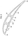
- the main wall 120 defines a first generally concave pressure sidewall 122 and a second generally convex suction sidewall 124, see Fig. 2 .
- the first and second sidewalls 122 and 124 are joined together at a leading edge 126 and a trailing edge 128.
- the main wall 120 also defines, in the illustrated embodiment, a plurality of interior cavities 130.
- the main wall 120, near the cavities 130, has a wall thickness extending from an external surface 120A of the main wall 120 to an interior cavity 130.
- the main wall 120 comprises a mid-point MP located between a base 20A of the airfoil 20 and a tip 20B of the airfoil, see Fig. 1 .
- the main wall 120 further comprises an outer radial section OS extending from a location near the mid-point MP to the tip 20B.
- the outer radial section OS is defined in the embodiment illustrated in Fig. 1 as comprising first, second and third radial portions RP 1 - RP 3 .
- Each radial portion may define a resolution of a machining process of the present invention.
- only three radial portions RP 1 - RP 3 are provided in the embodiment of Fig. 1 .
- a higher resolution will be desirable such that many more than three radial portions will be defined.
- the number of radial portions can be defined as comprising less than three portions or more than three portions.
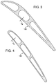
- the outer section OS has a final wall thickness that generally varies along its length such that the final thickness is greatest near the mid-point MP, see thickness T A in Fig. 2 , and gradually decreases to a minimum thickness near the tip 20B, see thickness T c in Fig. 4 .
- a thickness T B at an intermediate location along the outer section OS is illustrated in Fig. 3 and is less than thickness T A but greater than thickness T c near the tip 20B such that T A > T B > T c .
- the thickness T c near the tip 20B may fall within a range of from about 0.7 mm to about 1.5 mm.
- an airfoil is cast such that the main wall thickness at the outer section OS is greater than a final thickness, i.e., the main wall thickness is cast so as to be overly thick.
- the outer radial section OS may be cast such that it has a substantially constant thickness when moving radially from near the mid-point MP to the tip 20B such that the additional main wall material gradually increases in a generally continuous manner when moving radially from near the mid-point MP to the tip 20B.
- the main wall thickness of an inner radial section IS of the airfoil 20 extending from the base 20A to or near the mid-point MP is cast to the final thickness for the inner section IS such that no material removal from the inner section IS is required.
- the outer section OC of the airfoil casting is machined to a final desired thickness taking into account the locations of the interior cavities 130 formed via ceramic cores during the casting operation.
- a conventional thickness measuring device TMD is provided, which, in the illustrated embodiment comprises an ultrasonic measuring device 50 having a sonic thickness probe 50A for measuring the thickness of the outer section OS of the main wall 120 at any point such that non-destructive wall thickness data is collected from the casting C and provided to a computer system 60. It is also contemplated that the thickness measuring device may comprise any other known device, such as an X-ray inspection measuring apparatus, an eddy current measurement apparatus or a thermal imaging measuring device.
- the computer system 60 has stored in its memory model thickness data for all locations of the outer section OS of the airfoil 20.
- the computer system 60 compares the collected wall thickness data for the main wall outer section OS with the stored model thickness data to determine a desired amount of wall thickness material to be removed from the main wall outer section OS.
- the computer system 60 also takes into account the locations of the interior cavities 130 relative to the main wall external surface 120A so that a desired minimum main wall thickness is always maintained between the external surface 120A and an interior cavity 130.
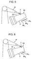
- the material removal device comprises a grit blasting apparatus 70, see Figs. 5 and 6 .
- the grit blasting apparatus 70 may spray a working fluid F comprising an abrasive grit, such as alumina, sand or the like, in a fluid medium, such as air or water, against the casting C.
- the grit blasting apparatus 70 preferably sprays the working fluid at the casting C at a non-orthogonal angle to an external surface of the main wall of the casting C. It is contemplated that the grit blasting working fluid F may strike the casting C in a circular area or footprint having a diameter of from about 0.125 inch to about 1 inch. It is also contemplated that other known material removal devices may be used in place of the grit blasting apparatus 70, such as a belt sander.
- the grit blasting apparatus 70 is used to remove material from the outer section OS of the main wall 120 on a layer by layer basis.
- the grip blasting apparatus 70 may be moved relative to the casting C, which may be held stationary via a fixture (not shown) or the casting C may be moved relative to the grit blasting apparatus 70. Movement of the grit blasting apparatus 70 and/or the casting C may be effected using a conventional moving device, which may be controlled via the computer system 60. It is contemplated that each layer of material removed from the casting C may have a thickness of from about 0.05 mm to about 0.25 mm.
- each radial portion may be defined to have a radial dimension substantially equal to the diameter or footprint of the grit blasting working fluid F striking the casting C.
- the grit blasting working fluid F may move repeatedly in a direction transverse to the radial direction to remove one or more layers of material from one or more of the radial portions.
- a first layer of material may be removed via the grit blasting apparatus from a plurality or all points or locations on each of the first, second and third radial portions RP 1 - RP 3 of the outer section OS.
- the term "layer” is intended to encompass a layer that is either uniform or varies in thickness in a direction transverse to the radial direction, e.g., in a direction extending from the leading edge 126 to the trailing edge 128.
- the amount of material removed in that layer may be uniform or vary in thickness in a direction transverse to the radial direction.
- a layer of material may be removed from only a transverse section of a radial portion such that no material is removed from one or more remaining transverse sections of the radial portion.
- the transverse sections of the radial portion may extend from the leading edge 126 to the trailing edge 128.
- the grit blasting apparatus 70 is illustrated as removing a further layer of material from both the second and third radial portions RP 2 and RP 3 , while not removing material from the first radial portion RP 1 .
- the process of measuring the thickness of the outer section OS of the main wall 120, comparing the measured thickness data with the stored model thickness data and removing an additional layer of material from the main wall 120 may be repeated numerous times until all points along the outer section OS, i.e., along the first, second and third radial portions RP 1 - RP 3 , are at a desired final thickness.
Description
- The present invention relates to a process for forming a long gas turbine engine blade having a main wall with a thin portion near a tip.
- Due to high operating temperatures, gas turbine engine blades are typically formed from a high density, nickel-based superalloy. Due to typical large flowpath diameters of gas turbine engines, the linear velocity of tips of corresponding turbine blades is extremely high. Hence, material at each blade tip exerts large centrifugal forces on the remainder of the blade. Any extra material at the blade tip cascades down the blade increasing radial blade pull. In order to cast longer blades, it is desirable to reduce the wall thickness at the blade tip to reduce radial blade pull. It is difficult, though, to cast long turbine blades having thin-walled portions near the tips. This is because a ceramic core, used during the casting process, shifts within process tolerances during casting, resulting in an uncertain position of the core relative to the tip of the blade. Hence, during the design process, wall thickness reduction at or near the tip is limited because of core shifting during casting. If wall thickness is reduced too much, the core may break through the wall near the tip during casting.
-
US 2005/091848 A1 discloses a process for the manufacture of a turbine blade comprising: casting as one piece a blade body and a first portion of an airfoil; forming a tip section having a tip cap and a second portion of an airfoil which is sized to fit on the first portion of the airfoil; and attaching the first portion of the airfoil to the second portion of the airfoil. There is also disclosed a process for repairing a turbine blade comprising: removing the tip cap and a portion of the airfoil from the blade to form a repair surface on the airfoil; forming a replacement tip section comprising a replacement tip cap and a replacement portion of the airfoil sized to fit onto the repair surface; and attaching the replacement tip section to the repair surface. - In accordance with the present invention, a process is provided for forming an airfoil for a gas turbine engine comprising: forming a casting of a gas turbine engine airfoil having a main wall and an interior cavity, the main wall having a wall thickness extending from an external surface of the main wall to the interior cavity, an outer radial section of the main wall extending from a location between a base and a tip of the airfoil casting to the tip and having a wall thickness greater than a final thickness; collecting, using a thickness measuring device, non-destructive wall thickness data of the casting; comparing, using a computer system, the collected wall thickness data with stored model thickness data to determine a desired amount of wall thickness material to be removed from one or more radial portions along the outer section of the main wall of the casting; effecting movement of a material removal apparatus and the casting relative to one another such that a layer of material is removed from the casting at one or more radial portions along the main wall of the casting; and repeating the collecting, comparing and effecting steps one or more times until the outer section of the main wall of the casting has a desired thickness.
- The repeating of the collecting, comparing and effecting steps one or more times preferably results in the thickness of the outer section of the main wall of the casting varying along the length of the outer section and, preferably, varying in a generally smooth continuous manner from the location between the base and the tip to the tip.
- The thickness of the outer section of the main wall near the tip may be less than the thickness of the outer section at the location between the base and the tip of the airfoil casting.
- Preferably, material is only removed from the casting at the outer section of the main wall.
- While the specification concludes with claims particularly pointing out and distinctly claiming the present invention, it is believed that the present invention will be better understood from the following description in conjunction with the accompanying Drawing Figures, in which like reference numerals identify like elements, and wherein:
-
Fig. 1 is a perspective view of a blade having a final thickness formed using the process of the present invention; -
Figs. 2-4 are cross sectional views taken along view lines 2-2, 3-3 and 4-4 inFig. 1 ; -
Figs. 5 and 6 are views of a grit blasting apparatus removing material from radial portions of an outer section of a main wall of a blade casting; and -
Fig. 7 is a view illustrating a conventional measuring apparatus, a computer system and a blade casting. - Referring now to
FIG. 1 , aturbine blade 10 formed in accordance with a process of the present invention is illustrated. Theblade 10 is adapted to be used in a turbine section (not shown) of a gas turbine engine (not shown). Within the turbine section are a series of rows of stationary vanes and rotating blades. Typically, there are four rows of blades in a turbine section. It is contemplated that theblade 10 illustrated inFIG. 1 may define the blade configuration for a third or fourth row of blades in the turbine section. - The blades are coupled to a shaft and disc assembly (not shown). Hot working gases from a combustor section (not shown) in the gas turbine engine travel to the rows of blades. As the working gases expand through the turbine section, the working gases cause the blades, and therefore the shaft and disc assembly, to rotate.
- The
turbine blade 10 comprises anairfoil 20, aroot 30 and aplatform 40, which, in the illustrated embodiment, may be formed as a single integral unit from an alloy material such as a metal alloy 247. Theroot 30 functions to couple theblade 10 to the shaft and disc assembly in the turbine section. Theairfoil 20 comprises amain wall 120 extending radially from theroot 30. Themain wall 120 defines a first generallyconcave pressure sidewall 122 and a second generallyconvex suction sidewall 124, seeFig. 2 . The first andsecond sidewalls edge 126 and atrailing edge 128. Themain wall 120 also defines, in the illustrated embodiment, a plurality ofinterior cavities 130. Themain wall 120, near thecavities 130, has a wall thickness extending from anexternal surface 120A of themain wall 120 to aninterior cavity 130. - In the illustrated embodiment, the
main wall 120 comprises a mid-point MP located between abase 20A of theairfoil 20 and atip 20B of the airfoil, seeFig. 1 . Themain wall 120 further comprises an outer radial section OS extending from a location near the mid-point MP to thetip 20B. The outer radial section OS is defined in the embodiment illustrated inFig. 1 as comprising first, second and third radial portions RP1- RP3. Each radial portion may define a resolution of a machining process of the present invention. For ease of illustration, only three radial portions RP1- RP3 are provided in the embodiment ofFig. 1 . However, it is contemplated that a higher resolution will be desirable such that many more than three radial portions will be defined. In any event, the number of radial portions can be defined as comprising less than three portions or more than three portions. - The outer section OS has a final wall thickness that generally varies along its length such that the final thickness is greatest near the mid-point MP, see thickness TA in
Fig. 2 , and gradually decreases to a minimum thickness near thetip 20B, see thickness Tc inFig. 4 . A thickness TB at an intermediate location along the outer section OS is illustrated inFig. 3 and is less than thickness TA but greater than thickness Tc near thetip 20B such that TA > TB > Tc. For an airfoil having a length L of from about 26 inches to about 35 inches, the thickness Tc near thetip 20B may fall within a range of from about 0.7 mm to about 1.5 mm. - As noted above, casting an airfoil having a long length L with a thickness of the main wall being very thin near the airfoil tip is difficult. In accordance with the present invention, an airfoil is cast such that the main wall thickness at the outer section OS is greater than a final thickness, i.e., the main wall thickness is cast so as to be overly thick. For example, the outer radial section OS may be cast such that it has a substantially constant thickness when moving radially from near the mid-point MP to the
tip 20B such that the additional main wall material gradually increases in a generally continuous manner when moving radially from near the mid-point MP to thetip 20B. Preferably, the main wall thickness of an inner radial section IS of theairfoil 20 extending from thebase 20A to or near the mid-point MP is cast to the final thickness for the inner section IS such that no material removal from the inner section IS is required. Subsequently, the outer section OC of the airfoil casting is machined to a final desired thickness taking into account the locations of theinterior cavities 130 formed via ceramic cores during the casting operation. - In
Fig. 7 , a casting C of the blade is illustrated. A conventional thickness measuring device TMD is provided, which, in the illustrated embodiment comprises anultrasonic measuring device 50 having asonic thickness probe 50A for measuring the thickness of the outer section OS of themain wall 120 at any point such that non-destructive wall thickness data is collected from the casting C and provided to acomputer system 60. It is also contemplated that the thickness measuring device may comprise any other known device, such as an X-ray inspection measuring apparatus, an eddy current measurement apparatus or a thermal imaging measuring device. Thecomputer system 60 has stored in its memory model thickness data for all locations of the outer section OS of theairfoil 20. Hence, thecomputer system 60 compares the collected wall thickness data for the main wall outer section OS with the stored model thickness data to determine a desired amount of wall thickness material to be removed from the main wall outer section OS. Thecomputer system 60 also takes into account the locations of theinterior cavities 130 relative to the main wallexternal surface 120A so that a desired minimum main wall thickness is always maintained between theexternal surface 120A and aninterior cavity 130. - In accordance with the illustrated embodiment, the material removal device comprises a
grit blasting apparatus 70, seeFigs. 5 and 6 . Thegrit blasting apparatus 70 may spray a working fluid F comprising an abrasive grit, such as alumina, sand or the like, in a fluid medium, such as air or water, against the casting C. Thegrit blasting apparatus 70 preferably sprays the working fluid at the casting C at a non-orthogonal angle to an external surface of the main wall of the casting C. It is contemplated that the grit blasting working fluid F may strike the casting C in a circular area or footprint having a diameter of from about 0.125 inch to about 1 inch. It is also contemplated that other known material removal devices may be used in place of thegrit blasting apparatus 70, such as a belt sander. - Preferably, the
grit blasting apparatus 70 is used to remove material from the outer section OS of themain wall 120 on a layer by layer basis. Thegrip blasting apparatus 70 may be moved relative to the casting C, which may be held stationary via a fixture (not shown) or the casting C may be moved relative to thegrit blasting apparatus 70. Movement of thegrit blasting apparatus 70 and/or the casting C may be effected using a conventional moving device, which may be controlled via thecomputer system 60. It is contemplated that each layer of material removed from the casting C may have a thickness of from about 0.05 mm to about 0.25 mm. - As noted above, three radial portions RP1 - RP3 are illustrated in
Fig. 1 , but, in order to increase the resolution of the material removal operation, more than three radial portions may be provided. Each radial portion may be defined to have a radial dimension substantially equal to the diameter or footprint of the grit blasting working fluid F striking the casting C. Hence, the grit blasting working fluid F may move repeatedly in a direction transverse to the radial direction to remove one or more layers of material from one or more of the radial portions. - As illustrated in
Fig. 5 , a first layer of material may be removed via the grit blasting apparatus from a plurality or all points or locations on each of the first, second and third radial portions RP1- RP3 of the outer section OS. The term "layer" is intended to encompass a layer that is either uniform or varies in thickness in a direction transverse to the radial direction, e.g., in a direction extending from theleading edge 126 to the trailingedge 128. Hence, when a layer of material is removed from one of the first, second and third radial portions RP1- RP3, the amount of material removed in that layer may be uniform or vary in thickness in a direction transverse to the radial direction. It is also contemplated that a layer of material may be removed from only a transverse section of a radial portion such that no material is removed from one or more remaining transverse sections of the radial portion. The transverse sections of the radial portion may extend from theleading edge 126 to the trailingedge 128. After the first layer of material has been removed from the first, second and third radial portions RP1 - RP3, theultrasonic measuring device 50 measures the thickness of the outer section OS of themain wall 120 at ail points and provides updated wall thickness data to thecomputer system 60. Thecomputer system 60 compares the updated measured wall thickness data with the stored model thickness data so as to determine any additional material to be removed from the outer section OS. For example, since the final wall thickness becomes thinner in a radial direction from near the mid-point MP to thetip 20B, it may not be necessary to remove any further material from the first radial portion RP1, yet one or more layers of material may still need to be removed from the second and third radial portions RP2 and RP3. InFig. 6 , thegrit blasting apparatus 70 is illustrated as removing a further layer of material from both the second and third radial portions RP2 and RP3, while not removing material from the first radial portion RP1. The process of measuring the thickness of the outer section OS of themain wall 120, comparing the measured thickness data with the stored model thickness data and removing an additional layer of material from themain wall 120 may be repeated numerous times until all points along the outer section OS, i.e., along the first, second and third radial portions RP1 - RP3, are at a desired final thickness.
Claims (10)
- A process for forming an airfoil (20) for a gas turbine engine comprising:forming a casting (C) of a gas turbine engine airfoil (20) having a main wall (120) and an interior cavity (130), the main wall (120) having a wall thickness extending from an external surface (120A) of the main wall (120) to the interior cavity (130), an outer radial section (OS) of the main wall (120) extending from a location between a base (20A) and a tip (20B) of the airfoil casting (C) to the tip (20B) having a wall thickness greater than a final thickness;collecting, using a thickness measuring device (50), non-destructive wall thickness data of the casting (C);comparing, using a computer system (60), the collected wall thickness data with stored model thickness data to determine a desired amount of wall thickness material to be removed from one or more radial portions (RP1 - RP3) along the outer section (OS) of the main wall (120) of the casting (C);effecting movement of a material removal apparatus (70) and the casting (C) relative to one another such that a layer of material is removed from the casting (C) at one or more radial portions (RP1 - RP3) along the main wall (120) of the casting (C); andrepeating the collecting, comparing and effecting steps one or more times until the outer section (OS) of the main wall (120) of the casting (C) has a desired thickness.
- The process as set out in claim 1, wherein said measuring device (50) comprises one of an ultrasonic device, an X-ray inspection apparatus, an eddy current measurement apparatus and a thermal imaging device.
- The process as set out in claim 1, wherein said airfoil casting (C) defines a gas turbine engine blade (10).
- The process as set out in claim 1, wherein said material removal apparatus (70) comprises a grit blasting apparatus (70).
- The process as set out in claim 4, wherein said grit blasting apparatus (70) sprays a working fluid (F) comprising an abrasive grit in a fluid medium against the casting (C).
- The process as set forth in claim 5, wherein said grit blasting apparatus (70) sprays the working fluid (F) at the casting (C) at a non-orthogonal angle to a surface (120A) of the casting (C).
- The process as set forth in claim 1, wherein repeating the collecting, comparing and effecting steps one or more times results in the thickness (TA, TB, TC) of the outer section (OS) of the main wall (120) of the casting (C) varying along the length of the outer section (OS).
- The process as set forth in claim 7, wherein the thickness (TC) of the outer section (OS) of the main wall (120) near the tip (20B) is less than the thickness (TA) of the outer section (OS) at the location between the base (20A) and the tip (20B) of the airfoil casting (C).
- The process as set forth in claim 7, wherein material is only removed from the casting (C) at the outer section (OS) of the main wall (120).
- The process as set forth in claim 1, wherein material is only removed from a transverse section of a radial portion (RP1 - RP3).
Applications Claiming Priority (2)
| Application Number | Priority Date | Filing Date | Title |
|---|---|---|---|
| US13/675,345 US8720526B1 (en) | 2012-11-13 | 2012-11-13 | Process for forming a long gas turbine engine blade having a main wall with a thin portion near a tip |
| PCT/US2013/069671 WO2014078305A1 (en) | 2012-11-13 | 2013-11-12 | Process for forming a long gas turbine engine blade having a main wall with a thin portion near a tip |
Publications (2)
| Publication Number | Publication Date |
|---|---|
| EP2920425A1 EP2920425A1 (en) | 2015-09-23 |
| EP2920425B1 true EP2920425B1 (en) | 2016-11-02 |
Family
ID=49759538
Family Applications (1)
| Application Number | Title | Priority Date | Filing Date |
|---|---|---|---|
| EP13803324.6A Active EP2920425B1 (en) | 2012-11-13 | 2013-11-12 | Process for forming a long gas turbine engine blade having a main wall with a thin portion near a tip |
Country Status (8)
| Country | Link |
|---|---|
| US (1) | US8720526B1 (en) |
| EP (1) | EP2920425B1 (en) |
| JP (1) | JP5973081B2 (en) |
| CN (1) | CN104812994B (en) |
| IN (1) | IN2015DN03335A (en) |
| RU (1) | RU2015117767A (en) |
| SA (1) | SA515360421B1 (en) |
| WO (1) | WO2014078305A1 (en) |
Families Citing this family (7)
| Publication number | Priority date | Publication date | Assignee | Title |
|---|---|---|---|---|
| US10260352B2 (en) | 2013-08-01 | 2019-04-16 | Siemens Energy, Inc. | Gas turbine blade with corrugated tip wall |
| EP3245386B1 (en) | 2015-01-13 | 2019-07-31 | General Electric Company | A composite airfoil with fuse architecture |
| US10101577B2 (en) * | 2015-04-13 | 2018-10-16 | Siemens Energy, Inc. | System to prognose gas turbine remaining useful life |
| CN108698128B (en) | 2016-04-27 | 2021-01-29 | 西门子能源美国公司 | Method of manufacturing a gas turbine engine blade and gas turbine engine blade |
| US11414997B2 (en) | 2017-01-13 | 2022-08-16 | Siemens Energy Global GmbH & Co. KG | Adaptive machining of cooled turbine airfoil |
| EP3511522A1 (en) | 2018-01-11 | 2019-07-17 | Siemens Aktiengesellschaft | Gas turbine blade and method for producing such blade |
| FR3103126B1 (en) * | 2019-11-20 | 2022-03-25 | Safran Aircraft Engines | Improved device and method for machining an aeronautical part |
Family Cites Families (33)
| Publication number | Priority date | Publication date | Assignee | Title |
|---|---|---|---|---|
| GB627295A (en) * | 1946-04-10 | 1949-08-05 | Adrian Albert Lombard | Improvements in or relating to the manufacture of guide vanes for axial-flow turbines and compressors |
| US3935766A (en) | 1973-10-09 | 1976-02-03 | Masters Christopher F | Method and apparatus for machining cylindrical tubes |
| GB8508391D0 (en) * | 1985-03-30 | 1985-05-09 | Ae Plc | Measurement of engineering components |
| US4959523A (en) | 1988-11-18 | 1990-09-25 | Hydro-Quebec | Method and apparatus for automatically sensing the configuration of a surface area and effecting a work function thereon |
| US5446673A (en) | 1993-03-30 | 1995-08-29 | General Electric Company | System and method for finish machining an in-process part having an inaccessible interior cavity |
| EP0894558A1 (en) * | 1997-07-29 | 1999-02-03 | Siemens Aktiengesellschaft | Turbine blade and method of fabrication of a turbine blade |
| US6850874B1 (en) | 1998-04-17 | 2005-02-01 | United Technologies Corporation | Method and apparatus for predicting a characteristic of a product attribute formed by a machining process using a model of the process |
| DE60026934T2 (en) * | 1999-06-02 | 2006-12-14 | General Electric Co. | Method for reducing the wall thickness after casting a turbine blade by means of EDM machining |
| DE10001516B4 (en) | 2000-01-15 | 2014-05-08 | Alstom Technology Ltd. | Non-destructive method for determining the layer thickness of a metallic protective layer on a metallic base material |
| US6376801B1 (en) | 2000-10-12 | 2002-04-23 | General Electric Company | Gas turbine component refurbishment apparatus and repair method |
| US6968290B2 (en) | 2001-03-27 | 2005-11-22 | General Electric Company | Electrochemical machining tool assembly and method of monitoring electrochemical machining |
| GB0114503D0 (en) * | 2001-06-14 | 2001-08-08 | Rolls Royce Plc | Air cooled aerofoil |
| US7204019B2 (en) | 2001-08-23 | 2007-04-17 | United Technologies Corporation | Method for repairing an apertured gas turbine component |
| US6701615B2 (en) | 2002-03-08 | 2004-03-09 | General Electric Company | Inspection and sorting system and method for part repair |
| JP2003344026A (en) * | 2002-05-27 | 2003-12-03 | Mitsubishi Heavy Ind Ltd | Computer program and method for inspecting hollow vane |
| DE10255346A1 (en) * | 2002-11-28 | 2004-06-09 | Alstom Technology Ltd | Method of making a turbine blade |
| US6969821B2 (en) * | 2003-06-30 | 2005-11-29 | General Electric Company | Airfoil qualification system and method |
| US20050091848A1 (en) * | 2003-11-03 | 2005-05-05 | Nenov Krassimir P. | Turbine blade and a method of manufacturing and repairing a turbine blade |
| US7010982B2 (en) | 2004-04-30 | 2006-03-14 | General Electric Company | Method of ultrasonically inspecting airfoils |
| DE502004004360D1 (en) * | 2004-05-03 | 2007-08-30 | Siemens Ag | Method for producing a hollow-cast component with internal coating |
| DE102005025338B4 (en) | 2005-05-31 | 2019-03-14 | Siemens Aktiengesellschaft | 08.Method for machining a workpiece |
| US7272529B2 (en) | 2005-07-08 | 2007-09-18 | Honeywell International, Inc. | Dual wall turbine blade ultrasonic wall thickness measurement technique |
| US7306026B2 (en) | 2005-09-01 | 2007-12-11 | United Technologies Corporation | Cooled turbine airfoils and methods of manufacture |
| GB0518153D0 (en) | 2005-09-07 | 2005-10-12 | Rolls Royce Plc | Apparatus for measuring wall thicknesses of objects |
| US8477154B2 (en) | 2006-03-20 | 2013-07-02 | Siemens Energy, Inc. | Method and system for interactive virtual inspection of modeled objects |
| US8244025B2 (en) | 2006-03-20 | 2012-08-14 | Siemens Energy, Inc. | Method of coalescing information about inspected objects |
| DE102006043339B4 (en) | 2006-09-15 | 2010-11-11 | Siemens Ag | Method and device for determining component wall thicknesses by means of thermography |
| DE102006050440A1 (en) * | 2006-10-26 | 2008-04-30 | Mtu Aero Engines Gmbh | Lightweight structure-turbine blade manufacturing method, involves casting blade unit with blade wall and hollow space surrounding blade wall, where blade unit extends radially from floor area to head area |
| US8087447B2 (en) | 2006-10-30 | 2012-01-03 | United Technologies Corporation | Method for checking wall thickness of hollow core airfoil |
| JP5490091B2 (en) * | 2008-03-28 | 2014-05-14 | アルストム テクノロジー リミテッド | Gas turbine guide vanes |
| US9177371B2 (en) | 2008-06-09 | 2015-11-03 | Siemens Energy, Inc. | Non-destructive examination data visualization and analysis |
| US8500411B2 (en) | 2010-06-07 | 2013-08-06 | Siemens Energy, Inc. | Turbine airfoil with outer wall thickness indicators |
| EP2469099B1 (en) * | 2010-12-23 | 2017-08-02 | Grundfos Management A/S | Rotor for a pump and core assembly and method for casting a wheel of a pump |
-
2012
- 2012-11-13 US US13/675,345 patent/US8720526B1/en active Active
-
2013
- 2013-11-12 WO PCT/US2013/069671 patent/WO2014078305A1/en active Application Filing
- 2013-11-12 CN CN201380059286.4A patent/CN104812994B/en active Active
- 2013-11-12 IN IN3335DEN2015 patent/IN2015DN03335A/en unknown
- 2013-11-12 JP JP2015542012A patent/JP5973081B2/en active Active
- 2013-11-12 RU RU2015117767A patent/RU2015117767A/en not_active Application Discontinuation
- 2013-11-12 EP EP13803324.6A patent/EP2920425B1/en active Active
-
2015
- 2015-05-12 SA SA515360421A patent/SA515360421B1/en unknown
Also Published As
| Publication number | Publication date |
|---|---|
| US20140130999A1 (en) | 2014-05-15 |
| WO2014078305A1 (en) | 2014-05-22 |
| IN2015DN03335A (en) | 2015-10-23 |
| CN104812994A (en) | 2015-07-29 |
| RU2015117767A (en) | 2017-01-10 |
| CN104812994B (en) | 2018-01-26 |
| SA515360421B1 (en) | 2016-12-18 |
| EP2920425A1 (en) | 2015-09-23 |
| US8720526B1 (en) | 2014-05-13 |
| JP2015536404A (en) | 2015-12-21 |
| JP5973081B2 (en) | 2016-08-23 |
Similar Documents
| Publication | Publication Date | Title |
|---|---|---|
| EP2920425B1 (en) | Process for forming a long gas turbine engine blade having a main wall with a thin portion near a tip | |
| US8206108B2 (en) | Turbine blades and methods of manufacturing | |
| EP3617451B1 (en) | Blade having porous, abradable element and corresponding processing method | |
| US5209644A (en) | Flow directing element for the turbine of a rotary machine and method of operation therefor | |
| US6520836B2 (en) | Method of forming a trailing edge cutback for a turbine bucket | |
| US10487665B2 (en) | Acoustic breakthrough detection | |
| JP2003201859A (en) | Restoration of compressor blade of gas turbine engine | |
| JP2004523687A (en) | Turbine blades with pre-segmented squealer tips | |
| US9102014B2 (en) | Method of servicing an airfoil assembly for use in a gas turbine engine | |
| MX2007014640A (en) | Method and fixture for manufacturing components. | |
| EP2186998A2 (en) | Forming modified turbine blades | |
| US20060162893A1 (en) | Method for the production of a casting mold | |
| EP3480426A1 (en) | Adaptively machining of a workpiece with an aerofoil shaped section | |
| JP5517587B2 (en) | Intermediate processed product of gas turbine blade, gas turbine blade and gas turbine, manufacturing method of intermediate processed product of gas turbine blade, and manufacturing method of gas turbine blade | |
| US11156106B2 (en) | Controlling extent of TBC sheet spall | |
| EP3765713B1 (en) | Mistuning of turbine blades with one or more internal cavities | |
| EP4166760A1 (en) | Angled tip rods | |
| EP3667016B1 (en) | Fan blade with integral metering device for controlling gas pressure within the fan blade and corresponding method of forming a fan blade | |
| US20230313691A1 (en) | Cooling passage exit opening cross-sectional area reduction for turbine system component | |
| EP3135427B1 (en) | Method, apparatus and computer program for repairing aerofoils of gas turbine engines |
Legal Events
| Date | Code | Title | Description |
|---|---|---|---|
| PUAI | Public reference made under article 153(3) epc to a published international application that has entered the european phase |
Free format text: ORIGINAL CODE: 0009012 |
|
| 17P | Request for examination filed |
Effective date: 20150416 |
|
| AK | Designated contracting states |
Kind code of ref document: A1 Designated state(s): AL AT BE BG CH CY CZ DE DK EE ES FI FR GB GR HR HU IE IS IT LI LT LU LV MC MK MT NL NO PL PT RO RS SE SI SK SM TR |
|
| AX | Request for extension of the european patent |
Extension state: BA ME |
|
| DAX | Request for extension of the european patent (deleted) | ||
| REG | Reference to a national code |
Ref country code: DE Ref legal event code: R079 Ref document number: 602013013645 Country of ref document: DE Free format text: PREVIOUS MAIN CLASS: F01D0005140000 Ipc: B22D0046000000 |
|
| GRAP | Despatch of communication of intention to grant a patent |
Free format text: ORIGINAL CODE: EPIDOSNIGR1 |
|
| RIC1 | Information provided on ipc code assigned before grant |
Ipc: B22D 46/00 20060101AFI20160509BHEP Ipc: F01D 5/18 20060101ALI20160509BHEP Ipc: F01D 5/14 20060101ALI20160509BHEP |
|
| INTG | Intention to grant announced |
Effective date: 20160602 |
|
| GRAS | Grant fee paid |
Free format text: ORIGINAL CODE: EPIDOSNIGR3 |
|
| GRAA | (expected) grant |
Free format text: ORIGINAL CODE: 0009210 |
|
| AK | Designated contracting states |
Kind code of ref document: B1 Designated state(s): AL AT BE BG CH CY CZ DE DK EE ES FI FR GB GR HR HU IE IS IT LI LT LU LV MC MK MT NL NO PL PT RO RS SE SI SK SM TR |
|
| REG | Reference to a national code |
Ref country code: GB Ref legal event code: FG4D |
|
| REG | Reference to a national code |
Ref country code: AT Ref legal event code: REF Ref document number: 841304 Country of ref document: AT Kind code of ref document: T Effective date: 20161115 Ref country code: CH Ref legal event code: EP |
|
| REG | Reference to a national code |
Ref country code: IE Ref legal event code: FG4D |
|
| REG | Reference to a national code |
Ref country code: DE Ref legal event code: R096 Ref document number: 602013013645 Country of ref document: DE |
|
| REG | Reference to a national code |
Ref country code: CH Ref legal event code: NV Representative=s name: SIEMENS SCHWEIZ AG, CH |
|
| REG | Reference to a national code |
Ref country code: FR Ref legal event code: PLFP Year of fee payment: 4 |
|
| PG25 | Lapsed in a contracting state [announced via postgrant information from national office to epo] |
Ref country code: LV Free format text: LAPSE BECAUSE OF FAILURE TO SUBMIT A TRANSLATION OF THE DESCRIPTION OR TO PAY THE FEE WITHIN THE PRESCRIBED TIME-LIMIT Effective date: 20161102 |
|
| REG | Reference to a national code |
Ref country code: NL Ref legal event code: MP Effective date: 20161102 |
|
| REG | Reference to a national code |
Ref country code: LT Ref legal event code: MG4D |
|
| REG | Reference to a national code |
Ref country code: AT Ref legal event code: MK05 Ref document number: 841304 Country of ref document: AT Kind code of ref document: T Effective date: 20161102 |
|
| PG25 | Lapsed in a contracting state [announced via postgrant information from national office to epo] |
Ref country code: GR Free format text: LAPSE BECAUSE OF FAILURE TO SUBMIT A TRANSLATION OF THE DESCRIPTION OR TO PAY THE FEE WITHIN THE PRESCRIBED TIME-LIMIT Effective date: 20170203 Ref country code: LT Free format text: LAPSE BECAUSE OF FAILURE TO SUBMIT A TRANSLATION OF THE DESCRIPTION OR TO PAY THE FEE WITHIN THE PRESCRIBED TIME-LIMIT Effective date: 20161102 Ref country code: NO Free format text: LAPSE BECAUSE OF FAILURE TO SUBMIT A TRANSLATION OF THE DESCRIPTION OR TO PAY THE FEE WITHIN THE PRESCRIBED TIME-LIMIT Effective date: 20170202 Ref country code: SE Free format text: LAPSE BECAUSE OF FAILURE TO SUBMIT A TRANSLATION OF THE DESCRIPTION OR TO PAY THE FEE WITHIN THE PRESCRIBED TIME-LIMIT Effective date: 20161102 Ref country code: NL Free format text: LAPSE BECAUSE OF FAILURE TO SUBMIT A TRANSLATION OF THE DESCRIPTION OR TO PAY THE FEE WITHIN THE PRESCRIBED TIME-LIMIT Effective date: 20161102 |
|
| PG25 | Lapsed in a contracting state [announced via postgrant information from national office to epo] |
Ref country code: ES Free format text: LAPSE BECAUSE OF FAILURE TO SUBMIT A TRANSLATION OF THE DESCRIPTION OR TO PAY THE FEE WITHIN THE PRESCRIBED TIME-LIMIT Effective date: 20161102 Ref country code: PT Free format text: LAPSE BECAUSE OF FAILURE TO SUBMIT A TRANSLATION OF THE DESCRIPTION OR TO PAY THE FEE WITHIN THE PRESCRIBED TIME-LIMIT Effective date: 20170302 Ref country code: BE Free format text: LAPSE BECAUSE OF NON-PAYMENT OF DUE FEES Effective date: 20161130 Ref country code: FI Free format text: LAPSE BECAUSE OF FAILURE TO SUBMIT A TRANSLATION OF THE DESCRIPTION OR TO PAY THE FEE WITHIN THE PRESCRIBED TIME-LIMIT Effective date: 20161102 Ref country code: PL Free format text: LAPSE BECAUSE OF FAILURE TO SUBMIT A TRANSLATION OF THE DESCRIPTION OR TO PAY THE FEE WITHIN THE PRESCRIBED TIME-LIMIT Effective date: 20161102 Ref country code: AT Free format text: LAPSE BECAUSE OF FAILURE TO SUBMIT A TRANSLATION OF THE DESCRIPTION OR TO PAY THE FEE WITHIN THE PRESCRIBED TIME-LIMIT Effective date: 20161102 Ref country code: IS Free format text: LAPSE BECAUSE OF FAILURE TO SUBMIT A TRANSLATION OF THE DESCRIPTION OR TO PAY THE FEE WITHIN THE PRESCRIBED TIME-LIMIT Effective date: 20170302 Ref country code: RS Free format text: LAPSE BECAUSE OF FAILURE TO SUBMIT A TRANSLATION OF THE DESCRIPTION OR TO PAY THE FEE WITHIN THE PRESCRIBED TIME-LIMIT Effective date: 20161102 Ref country code: HR Free format text: LAPSE BECAUSE OF FAILURE TO SUBMIT A TRANSLATION OF THE DESCRIPTION OR TO PAY THE FEE WITHIN THE PRESCRIBED TIME-LIMIT Effective date: 20161102 |
|
| PG25 | Lapsed in a contracting state [announced via postgrant information from national office to epo] |
Ref country code: DK Free format text: LAPSE BECAUSE OF FAILURE TO SUBMIT A TRANSLATION OF THE DESCRIPTION OR TO PAY THE FEE WITHIN THE PRESCRIBED TIME-LIMIT Effective date: 20161102 Ref country code: CZ Free format text: LAPSE BECAUSE OF FAILURE TO SUBMIT A TRANSLATION OF THE DESCRIPTION OR TO PAY THE FEE WITHIN THE PRESCRIBED TIME-LIMIT Effective date: 20161102 Ref country code: RO Free format text: LAPSE BECAUSE OF FAILURE TO SUBMIT A TRANSLATION OF THE DESCRIPTION OR TO PAY THE FEE WITHIN THE PRESCRIBED TIME-LIMIT Effective date: 20161102 Ref country code: EE Free format text: LAPSE BECAUSE OF FAILURE TO SUBMIT A TRANSLATION OF THE DESCRIPTION OR TO PAY THE FEE WITHIN THE PRESCRIBED TIME-LIMIT Effective date: 20161102 Ref country code: SK Free format text: LAPSE BECAUSE OF FAILURE TO SUBMIT A TRANSLATION OF THE DESCRIPTION OR TO PAY THE FEE WITHIN THE PRESCRIBED TIME-LIMIT Effective date: 20161102 |
|
| REG | Reference to a national code |
Ref country code: DE Ref legal event code: R097 Ref document number: 602013013645 Country of ref document: DE |
|
| REG | Reference to a national code |
Ref country code: IE Ref legal event code: MM4A |
|
| PG25 | Lapsed in a contracting state [announced via postgrant information from national office to epo] |
Ref country code: BE Free format text: LAPSE BECAUSE OF FAILURE TO SUBMIT A TRANSLATION OF THE DESCRIPTION OR TO PAY THE FEE WITHIN THE PRESCRIBED TIME-LIMIT Effective date: 20161102 Ref country code: BG Free format text: LAPSE BECAUSE OF FAILURE TO SUBMIT A TRANSLATION OF THE DESCRIPTION OR TO PAY THE FEE WITHIN THE PRESCRIBED TIME-LIMIT Effective date: 20170202 Ref country code: SM Free format text: LAPSE BECAUSE OF FAILURE TO SUBMIT A TRANSLATION OF THE DESCRIPTION OR TO PAY THE FEE WITHIN THE PRESCRIBED TIME-LIMIT Effective date: 20161102 |
|
| PLBE | No opposition filed within time limit |
Free format text: ORIGINAL CODE: 0009261 |
|
| STAA | Information on the status of an ep patent application or granted ep patent |
Free format text: STATUS: NO OPPOSITION FILED WITHIN TIME LIMIT |
|
| PG25 | Lapsed in a contracting state [announced via postgrant information from national office to epo] |
Ref country code: MC Free format text: LAPSE BECAUSE OF FAILURE TO SUBMIT A TRANSLATION OF THE DESCRIPTION OR TO PAY THE FEE WITHIN THE PRESCRIBED TIME-LIMIT Effective date: 20161102 Ref country code: LU Free format text: LAPSE BECAUSE OF NON-PAYMENT OF DUE FEES Effective date: 20161130 |
|
| 26N | No opposition filed |
Effective date: 20170803 |
|
| REG | Reference to a national code |
Ref country code: FR Ref legal event code: PLFP Year of fee payment: 5 |
|
| PG25 | Lapsed in a contracting state [announced via postgrant information from national office to epo] |
Ref country code: IE Free format text: LAPSE BECAUSE OF NON-PAYMENT OF DUE FEES Effective date: 20161112 Ref country code: SI Free format text: LAPSE BECAUSE OF FAILURE TO SUBMIT A TRANSLATION OF THE DESCRIPTION OR TO PAY THE FEE WITHIN THE PRESCRIBED TIME-LIMIT Effective date: 20161102 |
|
| PG25 | Lapsed in a contracting state [announced via postgrant information from national office to epo] |
Ref country code: HU Free format text: LAPSE BECAUSE OF FAILURE TO SUBMIT A TRANSLATION OF THE DESCRIPTION OR TO PAY THE FEE WITHIN THE PRESCRIBED TIME-LIMIT; INVALID AB INITIO Effective date: 20131112 |
|
| PG25 | Lapsed in a contracting state [announced via postgrant information from national office to epo] |
Ref country code: CY Free format text: LAPSE BECAUSE OF FAILURE TO SUBMIT A TRANSLATION OF THE DESCRIPTION OR TO PAY THE FEE WITHIN THE PRESCRIBED TIME-LIMIT Effective date: 20161102 Ref country code: MK Free format text: LAPSE BECAUSE OF FAILURE TO SUBMIT A TRANSLATION OF THE DESCRIPTION OR TO PAY THE FEE WITHIN THE PRESCRIBED TIME-LIMIT Effective date: 20161102 |
|
| PG25 | Lapsed in a contracting state [announced via postgrant information from national office to epo] |
Ref country code: MT Free format text: LAPSE BECAUSE OF NON-PAYMENT OF DUE FEES Effective date: 20161112 |
|
| PG25 | Lapsed in a contracting state [announced via postgrant information from national office to epo] |
Ref country code: TR Free format text: LAPSE BECAUSE OF FAILURE TO SUBMIT A TRANSLATION OF THE DESCRIPTION OR TO PAY THE FEE WITHIN THE PRESCRIBED TIME-LIMIT Effective date: 20161102 |
|
| PG25 | Lapsed in a contracting state [announced via postgrant information from national office to epo] |
Ref country code: AL Free format text: LAPSE BECAUSE OF FAILURE TO SUBMIT A TRANSLATION OF THE DESCRIPTION OR TO PAY THE FEE WITHIN THE PRESCRIBED TIME-LIMIT Effective date: 20161102 |
|
| REG | Reference to a national code |
Ref country code: DE Ref legal event code: R082 Ref document number: 602013013645 Country of ref document: DE Representative=s name: ROTH, THOMAS, DIPL.-PHYS. DR., DE |
|
| PGFP | Annual fee paid to national office [announced via postgrant information from national office to epo] |
Ref country code: GB Payment date: 20231121 Year of fee payment: 11 |
|
| PGFP | Annual fee paid to national office [announced via postgrant information from national office to epo] |
Ref country code: IT Payment date: 20231124 Year of fee payment: 11 Ref country code: FR Payment date: 20231123 Year of fee payment: 11 Ref country code: DE Payment date: 20231127 Year of fee payment: 11 Ref country code: CH Payment date: 20231201 Year of fee payment: 11 |