EP2920106B1 - A method for filling bottles - Google Patents
A method for filling bottles Download PDFInfo
- Publication number
- EP2920106B1 EP2920106B1 EP13838156.1A EP13838156A EP2920106B1 EP 2920106 B1 EP2920106 B1 EP 2920106B1 EP 13838156 A EP13838156 A EP 13838156A EP 2920106 B1 EP2920106 B1 EP 2920106B1
- Authority
- EP
- European Patent Office
- Prior art keywords
- liquid
- gas
- pressure
- containers
- filling
- Prior art date
- Legal status (The legal status is an assumption and is not a legal conclusion. Google has not performed a legal analysis and makes no representation as to the accuracy of the status listed.)
- Not-in-force
Links
Images


Classifications
-
- A—HUMAN NECESSITIES
- A23—FOODS OR FOODSTUFFS; TREATMENT THEREOF, NOT COVERED BY OTHER CLASSES
- A23L—FOODS, FOODSTUFFS, OR NON-ALCOHOLIC BEVERAGES, NOT COVERED BY SUBCLASSES A21D OR A23B-A23J; THEIR PREPARATION OR TREATMENT, e.g. COOKING, MODIFICATION OF NUTRITIVE QUALITIES, PHYSICAL TREATMENT; PRESERVATION OF FOODS OR FOODSTUFFS, IN GENERAL
- A23L2/00—Non-alcoholic beverages; Dry compositions or concentrates therefor; Their preparation
- A23L2/52—Adding ingredients
- A23L2/54—Mixing with gases
-
- B—PERFORMING OPERATIONS; TRANSPORTING
- B67—OPENING, CLOSING OR CLEANING BOTTLES, JARS OR SIMILAR CONTAINERS; LIQUID HANDLING
- B67C—CLEANING, FILLING WITH LIQUIDS OR SEMILIQUIDS, OR EMPTYING, OF BOTTLES, JARS, CANS, CASKS, BARRELS, OR SIMILAR CONTAINERS, NOT OTHERWISE PROVIDED FOR; FUNNELS
- B67C3/00—Bottling liquids or semiliquids; Filling jars or cans with liquids or semiliquids using bottling or like apparatus; Filling casks or barrels with liquids or semiliquids
- B67C3/02—Bottling liquids or semiliquids; Filling jars or cans with liquids or semiliquids using bottling or like apparatus
- B67C3/06—Bottling liquids or semiliquids; Filling jars or cans with liquids or semiliquids using bottling or like apparatus using counterpressure, i.e. filling while the container is under pressure
- B67C3/12—Pressure-control devices
-
- A—HUMAN NECESSITIES
- A23—FOODS OR FOODSTUFFS; TREATMENT THEREOF, NOT COVERED BY OTHER CLASSES
- A23L—FOODS, FOODSTUFFS, OR NON-ALCOHOLIC BEVERAGES, NOT COVERED BY SUBCLASSES A21D OR A23B-A23J; THEIR PREPARATION OR TREATMENT, e.g. COOKING, MODIFICATION OF NUTRITIVE QUALITIES, PHYSICAL TREATMENT; PRESERVATION OF FOODS OR FOODSTUFFS, IN GENERAL
- A23L3/00—Preservation of foods or foodstuffs, in general, e.g. pasteurising, sterilising, specially adapted for foods or foodstuffs
- A23L3/16—Preservation of foods or foodstuffs, in general, e.g. pasteurising, sterilising, specially adapted for foods or foodstuffs by heating loose unpacked materials
-
- B—PERFORMING OPERATIONS; TRANSPORTING
- B67—OPENING, CLOSING OR CLEANING BOTTLES, JARS OR SIMILAR CONTAINERS; LIQUID HANDLING
- B67C—CLEANING, FILLING WITH LIQUIDS OR SEMILIQUIDS, OR EMPTYING, OF BOTTLES, JARS, CANS, CASKS, BARRELS, OR SIMILAR CONTAINERS, NOT OTHERWISE PROVIDED FOR; FUNNELS
- B67C3/00—Bottling liquids or semiliquids; Filling jars or cans with liquids or semiliquids using bottling or like apparatus; Filling casks or barrels with liquids or semiliquids
- B67C3/02—Bottling liquids or semiliquids; Filling jars or cans with liquids or semiliquids using bottling or like apparatus
- B67C3/06—Bottling liquids or semiliquids; Filling jars or cans with liquids or semiliquids using bottling or like apparatus using counterpressure, i.e. filling while the container is under pressure
- B67C3/10—Bottling liquids or semiliquids; Filling jars or cans with liquids or semiliquids using bottling or like apparatus using counterpressure, i.e. filling while the container is under pressure preliminary filling with inert gases, e.g. carbon dioxide
-
- B—PERFORMING OPERATIONS; TRANSPORTING
- B67—OPENING, CLOSING OR CLEANING BOTTLES, JARS OR SIMILAR CONTAINERS; LIQUID HANDLING
- B67C—CLEANING, FILLING WITH LIQUIDS OR SEMILIQUIDS, OR EMPTYING, OF BOTTLES, JARS, CANS, CASKS, BARRELS, OR SIMILAR CONTAINERS, NOT OTHERWISE PROVIDED FOR; FUNNELS
- B67C3/00—Bottling liquids or semiliquids; Filling jars or cans with liquids or semiliquids using bottling or like apparatus; Filling casks or barrels with liquids or semiliquids
- B67C3/02—Bottling liquids or semiliquids; Filling jars or cans with liquids or semiliquids using bottling or like apparatus
- B67C3/22—Details
- B67C2003/226—Additional process steps or apparatuses related to filling with hot liquids, e.g. after-treatment
Definitions
- the present invention relates to a method of filling non-carbonated beverages into thin-walled containers stabilized by internal pressure. More specifically, the present invention relates to dissolving gas in liquid to properly control the internal pressure of flexible or semi-flexible containers during and after processing.
- Typical beverages can be in general classified into carbonated and noncarbonated classes of beverages.
- Traditional glass containers have been the mainstay for more than a century.
- the increasingly popular flexible or semi-flexible containers raise the attention to a proper control of the internal package pressure during and after processing.
- Carbonated beverages being oversaturated, require the flexible packaging to withstand the positive higher internal pressure compared to the external atmospheric pressure.
- Noncarbonated beverages particularly when processed in hot filling, are associated with negative internal pressure compared to the surrounding pressure.
- the hot filling follows usually a thermal disinfection process, and thus, as the product is cooled (for instance, on the shelf), a negative pressure drop is developed, whereby the external pressure exerted on the packaging is higher than the internal pressure.
- beverages and food industries have long utilized nitrogen gas for bottling and packaging applications.
- WO 99/02406 discloses a method of producing a liquid product packed in cans or bottles or other suitable containers.
- the method includes injecting one or more of nitrogen, carbon dioxide and nitrous oxide gas into the liquid product.
- One preferred feature of the method is to chill the liquid product prior to injecting gas.
- Another preferred feature is to add liquid nitrogen to the head spaces of filled containers before closing the containers.
- US 2004/0035089 describes a method and installation for packaging a liquid product in thin-walled packages using an inert gas, such as nitrogen; and/or carbon dioxide, in the gaseous state that is introduced into the chilled liquid by means of an injector, the liquid becoming saturated or supersaturated with which gas(es).
- an inert gas such as nitrogen
- carbon dioxide in the gaseous state that is introduced into the chilled liquid by means of an injector, the liquid becoming saturated or supersaturated with which gas(es).
- GB 2134496 describes a method of filling cans with substantially non-carbonated drinks according to the preamble of claim 1, in which method N 2 gas and CO 2 gas are dissolved as a mixture under pressure in the drink. Then, a predetermined quantity of the drink is introduced into the can at the same temperature and pressure at which the N 2 and CO 2 gases were dissolved in predetermined ratio in the drink and N 2 gas and/or a CO 2 containing inert gas is supplied over the surface of the drink in the can, substantially replacing the air in the head space in the can, while the can is open between the filling and sealing of the can.
- GB 2241941 describes a method of charging containers, especially thin-walled cans, with a low-carbonated liquid such as beer including dissolving carbon dioxide in the liquid, and dissolving nitrogen in the liquid while circulating the liquid through a chiller and thus the dissolution is carried out at a suitable sub-ambient temperature.
- a low-carbonated liquid such as beer including dissolving carbon dioxide in the liquid, and dissolving nitrogen in the liquid while circulating the liquid through a chiller and thus the dissolution is carried out at a suitable sub-ambient temperature.
- EP 0489589 describes a method for canning of a non-carbonated liquid food product according to which nitrogen is dissolved in the product at a temperature between 0 and 4°C where the product is held under nitrogen pressure in a holding tank for a period of time sufficient to permit froth to subside.
- the filled cans are thereupon closed fluid-tight, and the nitrogen comes out of solution in each closed can to create a super atmospheric pressure therein.
- prior methods comprise injecting nitrogen few times the amount required to saturate the beverages, and/or including the step of chilling the liquid product to a predetermined temperature, and/or introducing a gas mixture of CO 2 /N 2 in the product (with predetermined ratio), assuming that super saturated liquid in nitrogen is able to retain the nitrogen in excess of the saturation level over a prolonged period.
- an aim of the present invention is to provide a general method and comprehensive principles for pressure build-up and control in a hot fill process of noncarbonated products.
- Another aim of the present invention is to treat the complete line of production, or filler in accordance to the local pressure/temperature conditions rather than dealing with moving single containers.
- the proposed method is nitrogen gas saving and independent of line stoppage, line speed variation or any break time problems associated with other line equipment.
- One of the features of the present invention is to operate (the filling) with sub-saturated liquid state so that the escape of the gas is not dramatic but of a minor effect.
- the gas may be nitrogen or any other inert gas selected in accordance to the required pressure build-up, the product properties, filling conditions (e.g. filling temperature for instance), location of gas injection along the line, etc.
- the CO 2 concentration may decrease since the external CO 2 ambient concentration is ⁇ 1 %.
- the carbonation effect is practically of a very minor level and diminishes immediately after opening.
- the low level of CO 2 used may bear a two-fold goal: (1) pressure build-up, and (2) light carbonated products at a desired level.
- nitrous oxide is a non-toxic gas which is not flammable, has no color or odor, is slightly sweet and does not imitate. Therefore, it is widely used in the field of medicine, recreation, cooking and is licensed as food additive.
- the nitrous oxide gas is used in food services, e.g. cooking sprays, because it prevents the growth of bacteria, or it is filled in snack foods to displace the bacteria. It is also utilized as a foaming or mixing agent (in dairy processes for example, in making whipped cream, etc.).
- nitrous-oxide cartridges are popular and are government approved food additives. It is also becoming a common alternative to carbon dioxide (cartridges) for cooling food products.
- nitrous oxide is considered to be a comparatively quite safer sedative even if inhaled accidentally. There is no "hangover" effect - the gas is eliminated from the body within 3-5 minutes after the gas supply is stopped. Nitrous oxide is not an allergen. Some side effects appear only if administered in very high doses and for a very long period in breathing. As such it is a popular source of entertainment and enjoyment. It is a real challenge nowadays for regulating the use of N 2 O is to avoid shifting recreational use towards other intensive methods.
- N 2 O is inert at room temperature and it dissolves in water to give neutral solution.
- the equilibrium that exists when nitrous oxide is dissolved in water lies far to the left: N 2 O + H 2 O H 2 N 2 O 2 (7)
- utilizing nitrous oxide for pressure build-up may result in very moderate gasified products having a light characteristic of "happy drink", absolutely safe (as you can drive home and don't need an escort), and can be produced with various controlled levels of gasification.
- the aim of utilizing nitrous oxide is two-folds; first, for pressure build-up in practically very low concentration or for both pressure build-up and in happy light products in mild concentrations.
- Micro/nano bubbles are relatively of small rise velocity and are generated by various types of generators. In contrast to ordinary macro-bubbles which rise rapidly and burst at the interface, micro bubbles remain suspended in the liquid for an extended period and dissolve in the liquid phase.
- micro/nano-bubbles One of the most important features of micro/nano-bubbles is their high surface area to volume ratio which leads to high solubility in liquid and to an extremely stable late super-saturation solution.
- the gasification process (carbonation or nitrogenation) is carried out by utilizing micro/nano-bubbles.
- micro-bubbles may maintain late supersaturation due to their long life term before being completely dissolved.
- the gas volume (CO 2 , N 2 or N 2 O) is retained in the bubble and is released to the gas phase (head space) only after sealing the containers and after the product is cooled to the shelf temperature.
- the initial pressure in the head space will not increase immediately after sealing the container (due to immediate intense gas escape as associated with oversaturation), but instead, the pressure in the head space will decline and gas will escape the liquid phase to compensate such decline only sometime after the product cools down.
- a filling method may comprise:
- a filling method may comprise:
- a filling method may comprise:
- a filling method may comprise:
- the gas is an inert suitable gas.
- the suitable gas may be selected from N 2 , N 2 O, or any combination of these.
- the gas provides pressure build-up.
- the gas may be N 2 O which provides pressure build-up.
- the N 2 O may create a happy mood light product.
- non-carbonated liquid may comprise one or more components.
- pasteurization is carried out at an elevated temperature ranging from 60 to 90°C.
- feeding the gas into the non-carbonated liquid is carried out at a temperature ranging from ambient to 95°C.
- the above method further comprising keeping the liquid temperature (T L ) ranging in the filler unit from ambient to 95°C.
- the pressure along the feed line ranges from 1 to 10 bars.
- the pressure at the entrance of the filler unit ranges from 1 to 10 bars.
- the containers are kept at around the ambient temperature or below.
- a filling method may comprise:
- the second temperature may be lower than the first temperature. Furthermore, the second temperature may be higher than the first temperature.
- the pressure build-up in the head space is the most significant characteristic of the present invention.
- the pressure build-up in the head space is highly important as it keeps the containers safe for long periods of time.
- the volume of the head space in the containers determines the required pressure of the dissolved gas in the non-carbonated liquid to produce pressure build-up in the head space and/or gasification of the non-carbonated liquid.
- Figs. 1 and 2 enable maintaining a sub-saturation level throughout the entire hot or cold -fill line of non-carbonated products, the hot fill line being in accordance with the present invention.
- the general case of varying temperature along the line is elaborated below.
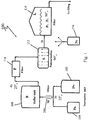
- FIG. 1 is a schematic illustration of a process 100 for pressure build-up and control in a hot-fill line of non-carbonated products.
- water 102 and component A 104 are mixed in mixer unit 106.
- the well mixed product is then passed through a buffer tank 108 to a filtering system 110.
- the temperature so far remains practically unchanged (around 25°C).
- Pasteurization by heat takes place at the thermal unit 112, wherefrom the product is transferred to and maintained in the filler unit 114, at a temperature, T L , ranging from 86°C to 90°C.
- Nitrogen gas 116 from a Nitrogen source N 2 (or any other gases as noted above), is fed into the feed line to the filler unit 114, at pressure P i > P L , where P L is the pressure at the filler unit 114.
- the pressure, P L is maintained at its required (design) value, by the aid of the Nitrogen 116. It should be noted, however, that Nitrogen can be injected anywhere along the line.
- the pressure along the line is roughly about 4 bars. However, due to pressure drop along the line, the pressure at the entrance of the filler unit 114 is somewhat lower, i.e., about 2-3 bars.
- the product is fed into the containers which are usually kept at a surrounding temperature of 25°C.
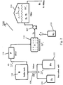
- Fig. 2 is a schematic illustration of a process 200 which is identical to process 100 in most parts aside for pump 202 which is additional to process 200.
- Pump 202 raises the pressure of the product prior to its entry to filler 114.
- Process 100 is of a typical line, whereby the pressure is highest at the entry and decreases along the line, whereas process 200 includes a pressure rise downstream due to pumping of the product to the filler unit 114.
- process 100 is characterized by low pressure at the filler unit 114 while in process 200 the pressure at the filler unit 114 is higher than that of the upstream.
- the product in the filler unit 114 may be in equilibrium or under-saturation corresponding to the pressure P L and temperature T L (86°C, for instance). From the filler unit 114, the product is fed into the containers which are usually at the surrounding temperature of 25°C. The containers may be either close or open at the filling process.
- Table 1 presents typical calculated values of pressure build-up as function of the filler pressure, P L , in a single phase (liquid) closed system.
- Filler pressure P L atm C L *(P L , T L 86°C) gr/liter P*(25°C) ⁇ ps P*(15°C) ⁇ Cs ⁇ Cr1 ⁇ Cr2 2 0.022 1.25 0.25 1.16 0.011 2 1.29 2.5 0.027 1.6 0.6 1.44 0.016 2.4 1.59 3 0.032 1.9 0.9 1.73 0.021 2.9 1.88 3.5 0.038 2.2 1.2 2.02 0.027 3.4 2.23 4 0.043 2.54 1.54 2.3 0.032 3.9 2.53
- the filler pressure, P L is varying from 2.0 to 2.5, 3.0, 3.5 and 4.0.
- P L concentration of CL* is calculated and used for calculating the resulting pressure at 25°C.
- ⁇ ps stands for pressure difference above the ambient pressure, and it represents the driving force for the gas to escape .
- ⁇ ps is relatively low, sustaining the assumption of minor gas loss.
- C*(1, 86°C) 0.011 gr/l by eq (1).
- the parameter ⁇ Cs represents the intensity or the physical driving force that liquid will reject the dissolved gas while filling.
- ⁇ Cr 1 and ⁇ Cr 2 are the ratio of the equilibrium concentration at the filler, C*(P L , 86°C) to either C*(1 atm, 86°C) or C*(1atm, 25°C), respectively;
- ⁇ Cr 1 C * P L , 86 ° C ⁇ C * 1,86 ° C
- ⁇ Cr 2 C * P L , 86 ° C / C * 1,25 ° C
- ⁇ Cr2 ⁇ Cr1 implies that gas nucleation which usually may initiate at the walls but is rather moderate, sustaining the assumption that the gas loss during the relatively short time filling is practically minor.
- filling containers of relatively cold walls are preferable from the point of view of holding the nitrogen in the bulk product.
- Tables 2-4 represent typical results for a variety of possible operations in two-phase systems where:
- the required filler pressure also increases, i.e., the required filler pressure for a 3% head space is 3.73 atm and 3.12 atm for 2% head space, compared to 3.2 and 2.77 atm respectively, when the head space is initially filled with pure nitrogen as in Table 2.
- Table 4 Another mode of interest is presented in Table 4, which refers to a closed system rather than open systems as presented in tables 2 and 3.
- Table 4 presents calculated values of pressure in the liquid phase in a two-phase closed system.
- P 0 Psat (atm) Closed-bottle filling VG/VL % T2 25°C P2 at 25°C T1 86°C P1t at 86°C P1 at 86°C P3 at 10°C *C2 at 25°C 1.58 5 25 1.25 86 1.58 1.58 1.16 0.021 1.62 3 25 1.25 86 1.62 1.62 1.15 0.021 1.66 2 25 1.25 86 1.66 1.66 1.14 0.021 1.73 1 25 1.25 86 1.73 1.73 1.13 0.021 1.43 25 1.10 86 1.43 1.43 1.02 0.019
- the filling process is carried out at a counter pressure identical to the pressure in the filler 114.
- the containers are practically closed during the filling process and the initial pressure in the containers is the filler pressure.
- This mode of filling is generally used in carbonated products.
- the gas may be injected at any point along the line.
- Table 6 includes various situations of pressure and temperature along the filling line, while pointing out in each case the minimal gas concentration to be used so that a sub-saturation is ensured through the whole line.
- Table 6 presents data corresponding to injection of the gas along various locations of the filling line.
- the minimal solubility C m is obviously at the high temperature of 86°C.
- the gas should be injected at a point along the line in which the solubility is minimal.
- C m 0.011 gr/l or corresponds to the highest temperature along the line (e.g., 86°C) which may produce an internal pressure of 0.63 atm at 25°C (see Exp. No. 1).
- micro/nano bubbles are used, late saturation or even oversaturation can be maintained for retaining the gas in the liquid bulk before approaching the gas-liquid interface.
- the gas in the form of micro/nano bubbles can be injected into the liquid prior to entering to the filler, while in the filler, or after exiting the filler just before filling the containers.
Description
- The present invention relates to a method of filling non-carbonated beverages into thin-walled containers stabilized by internal pressure. More specifically, the present invention relates to dissolving gas in liquid to properly control the internal pressure of flexible or semi-flexible containers during and after processing.
- Typical beverages can be in general classified into carbonated and noncarbonated classes of beverages. Traditional glass containers have been the mainstay for more than a century. However, the increasingly popular flexible or semi-flexible containers raise the attention to a proper control of the internal package pressure during and after processing.
- Carbonated beverages, being oversaturated, require the flexible packaging to withstand the positive higher internal pressure compared to the external atmospheric pressure. Noncarbonated beverages, particularly when processed in hot filling, are associated with negative internal pressure compared to the surrounding pressure. The hot filling follows usually a thermal disinfection process, and thus, as the product is cooled (for instance, on the shelf), a negative pressure drop is developed, whereby the external pressure exerted on the packaging is higher than the internal pressure. To overcome the pressure difference, i.e., to increase the internal pressure to a level comparable with the external pressure, beverages and food industries have long utilized nitrogen gas for bottling and packaging applications.
- In most related technologies, a micro-controlled drop of liquid nitrogen is injected into the container before it is capped and sealed. The basic idea behind most technologies is that when a small amount of liquid nitrogen hits the surface of the beverage or comes into the beverage core, it vaporizes and provides a pressure in the gas phase. In fact, and from the physical point of view, the cold liquid nitrogen (-190°c), expands immediately into gaseous nitrogen as it is exposed to the environment (at room temperature). Probably, for hot fill process, the evaporation process of the small drop might be more rapid and dramatic. Therefore, pressure build-up by so-called gentle nitrogen spray, just before sealing, on top of the beverage just before capping, requires an accurate charge of liquid nitrogen and a precisely timed drop of the liquid nitrogen into the head space of the container (bottle or can, etc.). Since the nitrogen injection is made individually per container, appropriate specialized installations are required to ensure a high purity precision of nitrogen dosing at various line speeds.
-
WO 99/02406 -
US 2004/0035089 describes a method and installation for packaging a liquid product in thin-walled packages using an inert gas, such as nitrogen; and/or carbon dioxide, in the gaseous state that is introduced into the chilled liquid by means of an injector, the liquid becoming saturated or supersaturated with which gas(es). -
GB 2134496 claim 1, in which method N2 gas and CO2 gas are dissolved as a mixture under pressure in the drink. Then, a predetermined quantity of the drink is introduced into the can at the same temperature and pressure at which the N2 and CO2 gases were dissolved in predetermined ratio in the drink and N2 gas and/or a CO2 containing inert gas is supplied over the surface of the drink in the can, substantially replacing the air in the head space in the can, while the can is open between the filling and sealing of the can. -
GB 2241941 -
EP 0489589 describes a method for canning of a non-carbonated liquid food product according to which nitrogen is dissolved in the product at a temperature between 0 and 4°C where the product is held under nitrogen pressure in a holding tank for a period of time sufficient to permit froth to subside. The filled cans are thereupon closed fluid-tight, and the nitrogen comes out of solution in each closed can to create a super atmospheric pressure therein. - As seen above, in all methods the liquid product is chilled prior to injecting gas, and in some methods, liquid nitrogen is added to the head spaces of filled containers before closing the containers. However, all relevant prior art references emphasize the need that a liquid has to be sufficiently oversaturated in order to ensure a sufficient amount of gas (nitrogen) in the product when sealed. As such, prior methods comprise injecting nitrogen few times the amount required to saturate the beverages, and/or including the step of chilling the liquid product to a predetermined temperature, and/or introducing a gas mixture of CO2/N2 in the product (with predetermined ratio), assuming that super saturated liquid in nitrogen is able to retain the nitrogen in excess of the saturation level over a prolonged period.
- Moreover, in most prior methods, in addition to injecting nitrogen into the liquid, an additional gas N2 and/or CO2 is supplied over the surface of the product in the container while the container is still open between filling and sealing the container. This raised great difficulties of control and/or complicated synchronization.
- It is worth noting at this point that the more saturated the liquid phase - the more dramatic and intensive is the gas escape. Besides, supersaturation is physically a less defined state and hence more difficult to control. As is shown herein, oversaturation is not necessarily needed in order to properly control the internal pressure of flexible or semi-flexible containers during and after processing.
- Thus, an aim of the present invention is to provide a general method and comprehensive principles for pressure build-up and control in a hot fill process of noncarbonated products. A method by which the exact amount of gas (or its corresponding pressure) required for a proper control of the final (shelf) internal pressure of flexible or semi-flexible containers is determined, and thus, prevents unnecessary oversaturation and gas waste.
- Another aim of the present invention is to treat the complete line of production, or filler in accordance to the local pressure/temperature conditions rather than dealing with moving single containers. In contrast to gas-flush systems and to methods dispensing nitrogen drop for each bottle in separate. Thus, the proposed method is nitrogen gas saving and independent of line stoppage, line speed variation or any break time problems associated with other line equipment.
- Last and not least, since the proposed method is associated with a well-defined physical state, it is easy to design and control.
- One of the features of the present invention is to operate (the filling) with sub-saturated liquid state so that the escape of the gas is not dramatic but of a minor effect.
- The gas may be nitrogen or any other inert gas selected in accordance to the required pressure build-up, the product properties, filling conditions (e.g. filling temperature for instance), location of gas injection along the line, etc. For instance, but not according to the invention, carbon dioxide, CO2, could be used for an internal pressure build-up to balance the external ambient pressure, P∞ =1 atm. In this case, a very light carbonated water may be obtained. For T = 25°C and P∞ = 1 atm, the equilibrium solubility of CO2 gas which may balance the ambient pressure is around 1.5 gr/l, far from regular carbonated beverages, but still not negligible and thus cannot be disregarded. However, after opening, the CO2 concentration may decrease since the external CO2 ambient concentration is ∼ 1 %. Thus, the carbonation effect is practically of a very minor level and diminishes immediately after opening.
- It is worth noting that health consideration between light carbonated or carbonated water relate mainly to the level of hydration. Some argue that carbonation may lead to the risk of dehydration (by developing pressure on the kidneys e.g.). On the other hand, researches have identified some health benefits of light carbonated water. Indeed, the health difference between carbonated and noncarbonated drinks is still under intense debate.
- Thus, utilizing CO2, the low level of CO2 used may bear a two-fold goal: (1) pressure build-up, and (2) light carbonated products at a desired level.
- Another application for the method and principles presented above, is the use of nitrous oxide (laughing gas), N2O, for pressure build-up and consequently for light gasification. Nitrous oxide is a non-toxic gas which is not flammable, has no color or odor, is slightly sweet and does not imitate. Therefore, it is widely used in the field of medicine, recreation, cooking and is licensed as food additive. The nitrous oxide gas is used in food services, e.g. cooking sprays, because it prevents the growth of bacteria, or it is filled in snack foods to displace the bacteria. It is also utilized as a foaming or mixing agent (in dairy processes for example, in making whipped cream, etc.).
- Aside from being an important component of food production, e.g. nitrous-oxide cartridges are popular and are government approved food additives. It is also becoming a common alternative to carbon dioxide (cartridges) for cooling food products.
- It is worth noting that nitrous oxide is considered to be a comparatively quite safer sedative even if inhaled accidentally. There is no "hangover" effect - the gas is eliminated from the body within 3-5 minutes after the gas supply is stopped. Nitrous oxide is not an allergen. Some side effects appear only if administered in very high doses and for a very long period in breathing. As such it is a popular source of entertainment and enjoyment. It is a real challenge nowadays for regulating the use of N2O is to avoid shifting recreational use towards other intensive methods.
- Another property of N2O is that it is inert at room temperature and it dissolves in water to give neutral solution. The equilibrium that exists when nitrous oxide is dissolved in water lies far to the left:
N2O + H2O = H2 N2 O2 (7)
- In view of the above, utilizing nitrous oxide for pressure build-up (clearly not in breathing) and in relatively small concentrations (due to its high Henry constant, see below), may result in very moderate gasified products having a light characteristic of "happy drink", absolutely safe (as you can drive home and don't need an escort), and can be produced with various controlled levels of gasification. Again, the aim of utilizing nitrous oxide is two-folds; first, for pressure build-up in practically very low concentration or for both pressure build-up and in happy light products in mild concentrations.
- Micro/nano bubbles are relatively of small rise velocity and are generated by various types of generators. In contrast to ordinary macro-bubbles which rise rapidly and burst at the interface, micro bubbles remain suspended in the liquid for an extended period and dissolve in the liquid phase.
- One of the most important features of micro/nano-bubbles is their high surface area to volume ratio which leads to high solubility in liquid and to an extremely stable late super-saturation solution.
- In view of the above characteristics of micro/nano-bubbles, the gasification process (carbonation or nitrogenation) is carried out by utilizing micro/nano-bubbles. Compared to the scale-time of filling containers (cans and bottles) up to their complete sealing which is of the order of seconds, micro-bubbles may maintain late supersaturation due to their long life term before being completely dissolved.
- As a direct result, the gas volume (CO2, N2 or N2O) is retained in the bubble and is released to the gas phase (head space) only after sealing the containers and after the product is cooled to the shelf temperature. Moreover, since gas is not released at the hot temperature, the initial pressure in the head space will not increase immediately after sealing the container (due to immediate intense gas escape as associated with oversaturation), but instead, the pressure in the head space will decline and gas will escape the liquid phase to compensate such decline only sometime after the product cools down.
- In accordance with the present invention, there is provided a method of filling flexible walled containers with liquid according to
claim 1. - Further aspects of the invention are defined by the dependent claims. Furthermore a filling method may comprise:
- providing a non-carbonated liquid in a filler unit;
- dissolving a suitable gas in said non-carbonated liquid at a sub saturation level at a first temperature in a first container;
- transferring the non carbonated liquid containing the dissolved gas into flexible walled containers to fill the containers to the top or to fill a pre-specified portion of the containers leaving an unfilled portion of the flexible walled containers as a head space and the liquid is in equilibrium or non equilibrium with the gas in the head space;
- closing the containers tightly;
- allowing the non-carbonated liquid containing the dissolved gas to reach a second temperature;
- Furthermore, a filling method may comprise:
- providing a non-carbonated liquid;
- passing the non-carbonated liquid through a buffer tank and through a filtering system;
- pasteurizing the non-carbonated liquid;
- dissolving a suitable gas in said non-carbonated liquid;
- passing the non-carbonated liquid containing the dissolved gas into a filler unit; and
- transferring the non-carbonated liquid containing the dissolved gas from the filler unit into containers and closing the containers.
- Furthermore, a filling method may comprise:
- providing a non-carbonated liquid;
- passing the non-carbonated liquid through a buffer tank and through a filtering system;
- pasteurizing the non-carbonated liquid;
- passing the non-carbonated liquid into a filler unit;
- feeding a suitable gas into the filler unit; and
- transferring the non-carbonated liquid containing the gas from the filler unit into containers and closing the containers.
- Furthermore, a filling method may comprise:
- providing a non-carbonated liquid;
- passing the non-carbonated liquid through a buffer tank and through a filtering system;
- pasteurizing the non-carbonated liquid;
- passing the non-carbonated liquid into a filler unit;
- exiting the non-carbonated liquid from said filler unit and transferring the non-carbonated liquid into containers, while transferring the non-carbonated liquid into containers, dissolving a suitable gas, and then closing the containers.
- Furthermore, the gas is an inert suitable gas.
- Furthermore, the suitable gas may be selected from N2, N2O, or any combination of these.
- Furthermore, the gas provides pressure build-up.
- Furthermore, the gas may be N2O which provides pressure build-up.
- Furthermore, the N2O may create a happy mood light product.
- Furthermore, the non-carbonated liquid may comprise one or more components.
- Furthermore, pasteurization is carried out at an elevated temperature ranging from 60 to 90°C.
- Furthermore, feeding the gas into the non-carbonated liquid is carried out at a temperature ranging from ambient to 95°C.
- Furthermore, the above method further comprising keeping the liquid temperature (TL) ranging in the filler unit from ambient to 95°C.
- Furthermore, the pressure along the feed line ranges from 1 to 10 bars.
- Furthermore, the pressure at the entrance of the filler unit ranges from 1 to 10 bars.
- Furthermore, the containers are kept at around the ambient temperature or below.
- Furthermore, the above method
may - further comprise adding a pump to a feed line to raise the pressure of the non-carbonated liquid prior to its entry into the filler unit. Furthermore, the containers are
- Furthermore, the above method
may - further comprise keeping the walls of the containers at ambient temperature or below during and after filling.
- A filling method may comprise:
- introducing a suitable gas at a sub-saturation level in the form of micro/nano-bubbles into a non-carbonated liquid at a first temperature in a first container;
- transferring the non-carbonated liquid containing the micro/nano-bubbles into containers to fill the containers to the top or to fill a pre-specified portion of the containers leaving an unfilled portion of the flexible walled containers as a head space and the gas in said non-carbonated liquid is in equilibrium or non-equilibrium with the gas in the head space;
- closing the containers tightly; and
- allowing the non-carbonated liquid containing the micro/nano-bubbles to reach a second temperature that is lower or higher than the first temperature;
- Furthermore, the second temperature may be lower than the first temperature. Furthermore, the second temperature may be higher than the first temperature.
- It should be noted that the pressure build-up in the head space is the most significant characteristic of the present invention. The pressure build-up in the head space is highly important as it keeps the containers safe for long periods of time. The volume of the head space in the containers determines the required pressure of the dissolved gas in the non-carbonated liquid to produce pressure build-up in the head space and/or gasification of the non-carbonated liquid.
-
-
Fig. 1 is a schematic illustration of a process for pressure build-up and control in a hot or cold -fill line of non-carbonated products. -
Fig. 2 is a schematic illustration of a process identical to the process illustrated inFig. 1 aside for an additional pump. -
Figs. 3 and4 elaborate the principles of sub-saturation operations. - The processes illustrated in
Figs. 1 and2 enable maintaining a sub-saturation level throughout the entire hot or cold -fill line of non-carbonated products, the hot fill line being in accordance with the present invention. The general case of varying temperature along the line is elaborated below. - Referring now to
Fig. 1 which is a schematic illustration of aprocess 100 for pressure build-up and control in a hot-fill line of non-carbonated products. - As seen in
Fig. 1 ,water 102 and component A 104 are mixed inmixer unit 106. The well mixed product is then passed through abuffer tank 108 to afiltering system 110. The temperature so far remains practically unchanged (around 25°C). - Pasteurization by heat takes place at the
thermal unit 112, wherefrom the product is transferred to and maintained in thefiller unit 114, at a temperature, TL, ranging from 86°C to 90°C. Nitrogen gas 116, from a Nitrogen source N2 (or any other gases as noted above), is fed into the feed line to thefiller unit 114, at pressure Pi > PL, where PL is the pressure at thefiller unit 114. The pressure, PL, is maintained at its required (design) value, by the aid of theNitrogen 116. It should be noted, however, that Nitrogen can be injected anywhere along the line. - Generally, in practice the pressure along the line is roughly about 4 bars. However, due to pressure drop along the line, the pressure at the entrance of the
filler unit 114 is somewhat lower, i.e., about 2-3 bars. - From the
filler unit 114, the product is fed into the containers which are usually kept at a surrounding temperature of 25°C. -
Fig. 2 is a schematic illustration of aprocess 200 which is identical to process 100 in most parts aside forpump 202 which is additional to process 200. Pump 202 raises the pressure of the product prior to its entry tofiller 114. -
Process 100 is of a typical line, whereby the pressure is highest at the entry and decreases along the line, whereasprocess 200 includes a pressure rise downstream due to pumping of the product to thefiller unit 114. Thus,process 100 is characterized by low pressure at thefiller unit 114 while inprocess 200 the pressure at thefiller unit 114 is higher than that of the upstream. These two processes are further analyzed below with regard to maintaining a sub-saturation level throughout the entire line. - In both
process 100 andprocess 200, the product in thefiller unit 114 may be in equilibrium or under-saturation corresponding to the pressure PL and temperature TL (86°C, for instance). From thefiller unit 114, the product is fed into the containers which are usually at the surrounding temperature of 25°C. The containers may be either close or open at the filling process. - Based on the value of the Henry's law constant at TL=86°C for Nitrogen in water, the solubility at the
filler unit 114 can be calculated as follows:
- For illustration, the variation of Henry constant (coefficient) with temperature is estimated by the so-called Van't Hoff relation, whereby;

- For Nitrogen, the corresponding values for Ci and H(T0) are;


- An analysis of the physical situation at the filling point for two cases of open and closed containers is presented as follows:
Table 1 presents typical calculated values of pressure build-up as function of the filler pressure, PL, in a single phase (liquid) closed system. Filler pressure PL atm CL*(PL, TL=86°C) gr/liter P*(25°C) Δ ps P*(15°C) ΔCs Δ Cr1 Δ Cr2 2 0.022 1.25 0.25 1.16 0.011 2 1.29 2.5 0.027 1.6 0.6 1.44 0.016 2.4 1.59 3 0.032 1.9 0.9 1.73 0.021 2.9 1.88 3.5 0.038 2.2 1.2 2.02 0.027 3.4 2.23 4 0.043 2.54 1.54 2.3 0.032 3.9 2.53 - For the present demonstration in Table 1, a constant temperature of TL =86°C corresponding to a hot fill process is used. CL* denotes the equilibrium solubility at (PL, TL), based on the Henry - constant at TL.
- The filler pressure, PL, is varying from 2.0 to 2.5, 3.0, 3.5 and 4.0. For each value of PL, the corresponding concentration CL* is calculated and used for calculating the resulting pressure at 25°C. However, according to the values of P*(25) in table 1, one can operate at sub-saturation level to yield P*(25)=1.0 atm.
- Thus, assuming (at first), that the filling process is fast enough, hence there is no nitrogen loss prior to sealing, then, the new equilibrium pressure at various temperatures is predicted. For instance, at a common shelf temperature of 25°C, the corresponding pressure P*(25°C) is always higher than atmospheric pressure, when the design filler pressure is PL>2 atm. As the product cools to 15°C (for instance before use), the internal pressure P*(15°C) is still sufficient to resist the external ambient pressure, P∞ = 1 atm.
- Also included in Table 1, is the super-saturation at the shelf temperature, T = 25°C, defined in terms of pressure difference as;

- Note that, Δ ps stands for pressure difference above the ambient pressure, and it represents the driving force for the gas to escape .Since p*(25°C) is the equilibrium pressure at the container walls TL=25°C. As seen in Table 1, Δ ps is relatively low, sustaining the assumption of minor gas loss.
- Another parameter Δ Cs can be defined in terms of the solubility difference as;

- The parameter Δ Cs represents the intensity or the physical driving force that liquid will reject the dissolved gas while filling. However, since the container walls are practically at 25°C during the filling process, this intensity can be related to C*(1 atm, 25°C) = 0.017 gr/l rather than to C*(1 atm, 86°C) =0.011 gr/l. Included in Table 1 are the ratios Δ Cr1 and Δ Cr2, which are the ratio of the equilibrium concentration at the filler, C*(PL, 86°C) to either C*(1 atm, 86°C) or C*(1atm, 25°C), respectively;


- Clearly, Δ Cr2<Δ Cr1 implies that gas nucleation which usually may initiate at the walls but is rather moderate, sustaining the assumption that the gas loss during the relatively short time filling is practically minor. As such, filling containers of relatively cold walls are preferable from the point of view of holding the nitrogen in the bulk product.
- Note that the analyses so far relate to the liquid phase alone; this is consistent with the assumption that the gas escape is minor. However, simultaneous two-phase modeling of the gas - liquid interaction can be carried out, if the head space volume is known. A rather more complicated calculation procedure yields whereby, the distribution of the nitrogen gas in both the liquid and gas phases. Such calculation procedure, which includes mathematical modeling as well as empirical solutions, reveals the dramatic effects of the head space in various filling conditions as indicated in tables 2-4.
- Tables 2-4 represent typical results for a variety of possible operations in two-phase systems where:
- P0 denotes the initial pressure at the head space at filling,
- VG/VL is the head space fraction,
- P2 is the design required pressure at temperature T2(=25°C for the purpose of illustration), and
- P1 is the required filler pressure at temperature T1(=86°C for the purpose of illustration), which is required to yield the desired pressure P2.
- As the filling pressure comes to an end, the new equilibrium pressure, immediately after sealing, is denoted by P1t. As the temperature decreases to T2 =25°C or T3=10°C, the corresponding pressures are P2 and P3. Included in the tables are also the concentration C2*(25°C).
- In principle, accounting for a given head space volume, a higher filler pressure is required to ensure the final P*(25°C). For instance, as shown in Table 1, in order to end up with gas pressure of P(25°C)=1.25 atm in a single phase (liquid) system, the required filler pressure is 2 atm. However, as shown in Table 2, in a two phase (liquid/gas) system, assuming the head space is 3%, the required filler pressure at 86°C is 3.2 atm. If the head space volume is about 2% of the total container volume, the required filler pressure decreases to 2.77 atm. Clearly, if the required final pressure is lower for instance, if P2 (25°C) is only 1.1 atm, the filler pressure will be only 2.51 atm for head space fraction of 3%.
- Seen in Table 3, as open container initially occupied with air (0.79N2), the required filler pressure also increases, i.e., the required filler pressure for a 3% head space is 3.73 atm and 3.12 atm for 2% head space, compared to 3.2 and 2.77 atm respectively, when the head space is initially filled with pure nitrogen as in Table 2.
- Another mode of interest is presented in Table 4, which refers to a closed system rather than open systems as presented in tables 2 and 3.
Table 4 presents calculated values of pressure in the liquid phase in a two-phase closed system. P0=Psat (atm) Closed-bottle filling VG/VL % T2 25°C P2 at 25°C T1 86°C P1t at 86°C P1 at 86°C P3 at 10°C *C2 at 25°C 1.58 5 25 1.25 86 1.58 1.58 1.16 0.021 1.62 3 25 1.25 86 1.62 1.62 1.15 0.021 1.66 2 25 1.25 86 1.66 1.66 1.14 0.021 1.73 1 25 1.25 86 1.73 1.73 1.13 0.021 1.43 25 1.10 86 1.43 1.43 1.02 0.019 - In this case, the filling process is carried out at a counter pressure identical to the pressure in the
filler 114. In fact, the containers are practically closed during the filling process and the initial pressure in the containers is the filler pressure. This mode of filling is generally used in carbonated products. - A comparison between the parameters of Table 4 with the corresponding parameters of Tables 2 and 3 indicates that the required filler pressures are much lower in the case of filling closed containers with counter pressure.
- It should be noted that in hot fillings, the vapor pressure of the liquid (water) is significant. For instance, at 86°C the vapor pressure is nearly 0.6 atm. Therefore, the partial pressure of the gas (of Nitrogen, for instance) just above the liquid interface is about 0.4 atm. An initial partial pressure of 0.4 atm instead of 1 or 0.79 atm yields higher P1 values than those in tables 2 and 3. Some typical values for comparison are shown in Table 5. Inspection of Tables 2, 3, and 5 indicates that it is of high importance to reduce the head space as much as possible particularly in hot fill processes.
Table 5 presents calculated values for various head space ratios in a two-phase open system where the head space is initially occupied by nitrogen and vapor. P0 atm VG/VL % T2 25° C P2 at 25° C T1 86°C P1t at 86°C P1 at 86°C 0.4 3 25 1.25 86 1.62 4.71 0.4 2 25 1.25 86 1.66 3.78 0.4 1 25 1.25 86 1.73 2.85 0.4 3 25 1.04 86 1.43 3.73 - It should be further noted that the illustrations so far relate to a filling temperature of TL=86°C. Clearly, a filling temperature that is lower than 86°C requires a lower pressure, PL or P1, to provide a shelf pressure of 1.25 atm (at 25°C).
- In addition, it should be noted that the gas may be injected at any point along the line. For illustration of the effects of the location of gas injection, Table 6 includes various situations of pressure and temperature along the filling line, while pointing out in each case the minimal gas concentration to be used so that a sub-saturation is ensured through the whole line.
Table 6 presents data corresponding to injection of the gas along various locations of the filling line. Exp No. HN2 atm·lit/gm 1639.3 2173.2 2585.8 1639.3 T(°C)= 25 60 86 25 1 P atm1 1 1 0.63 C=gr/l 0.017 0.013 Cm=0.011 0.011 2 P 1 2 2 1.06 C 0.017 0.026 0.022 Cm=0.018 3 P 1.24 2 2 1.24 C 0.021 0.026 0.022 Cm=0.021 4 P 3-4 3.5 2.5 1.6 C 0.051-0.068 0.045 Cm=0.027 0.027 5 P 3-4 3.5 2.75 1.74 C 0.051-0.068 0.045 0.030 0.030 - As seen in Table 6, for a constant pressure along the line as in Exp. No. 1, the minimal solubility Cm is obviously at the high temperature of 86°C. In order to prevent foaming along the line, the gas should be injected at a point along the line in which the solubility is minimal.
- For instance, if the pressure is roughly 1 atm along the line, then Cm = 0.011 gr/l or corresponds to the highest temperature along the line (e.g., 86°C) which may produce an internal pressure of 0.63 atm at 25°C (see Exp. No. 1). On the other hand, if the pressure along the line is 2 atm. (Exp. No. 2) then the minimal solubility Cm = 0.022 gr/l which is higher than the solubility of 0.017 gr/l, required to produce an internal pressure of 1 atm at 25°C. Thus, if Cm = 0.022 gr/l is injected at the high temperature, then an internal pressure of 1.27 atm is produced at 25°C, and an injection of 0.018 gr/l yields an internal pressure of 1 atm. Alternatively, Cm = 0.021 gr/l can be injected at 25°C before the pasteurization phase) but with pressure of 1.24 atm, ensuring that no foams develop at 86°C and 2 atm (Exp. No. 3). Experiments Nos. 4-5 in Table 6, represent the general case of both pressure and temperature variations along the line. When the minimal concentration is injected, sub-saturation is ensured along the line while a sufficiently positive internal pressure at the shelf-temperature (25°C) still prevails.
- It should be noted that the method and principles discussed above in relation to the schematic flow chart of
Figures 1 and2 can in fact be applied as well to any process for providing an internal pressure build-up as required. - The principle of sub-saturation operation is further elaborated in
Figs. 3 and4 . In mode A ofFig. 3 , the pressure monotonously decreases towards the filler. In mode B ofFig. 4 , on the other hand, the filling is carried out after raising the pressure to easily-controlled differential ΔP, such that filler pressure is at Pb = P* + ΔP. Thus, in mode A, the lower concentration Cb(<Ci) is injected at the high pressure zone upstream, point I, while in mode B, the filler pressure/temperature conditions are known, and the upstream pressure at injection is evaluated, so that Ci<Cb. Again, in both modes sub-saturation states are ensured. - Beyond that, if micro/nano bubbles are used, late saturation or even oversaturation can be maintained for retaining the gas in the liquid bulk before approaching the gas-liquid interface.
- It should be noted that the gas in the form of micro/nano bubbles can be injected into the liquid prior to entering to the filler, while in the filler, or after exiting the filler just before filling the containers.
wherein the head space has a volume fraction that determines the required pressure of the dissolved gas in the non-carbonated liquid in order to produce a desired pressure build-up in the head space. Dissolving gas in said non-carbonated liquid can be done anywhere along the line and not necessarily in the filler.
| P0 atm | VG/VL % | T2 25° C | P2 at 25° C | T1 86°C | P1t at 86°C | P1 at 86°C | P3 at 10°C | *C2 at 25°C |
| 1.00 | 5 | 25 | 1.25 | 86 | 1.58 | 4.05 | 1.16 | 0.021 g/l |
| 1.00 | 3 | 25 | 1.25 | 86 | 1.62 | 3.20 | 1.15 | 0.021 |
| 1.00 | 2 | 25 | 1.25 | 86 | 1.66 | 2.77 | 1.14 | 0.021 |
| 1.00 | 1 | 25 | 1.25 | 86 | 1.73 | 2.34 | 1.13 | 0.021 |
| 1.00 | 3 | 25 | 1.10 | 86 | 1.43 | 2.51 | 1.02 | 0.019 |
| P0 atm | VGVL % | T2 25° C | P2 at 25°C | T1 86°C | P1t at 86°C | P1 at 86° C | P3 at 10°C | *C2 at 25°C |
| 0.79 | 5 | 25 | 1.25 | 86 | 1.58 | 4.93 | 1.16 | 0.021 |
| 0.79 | 3 | 25 | 1.25 | 86 | 1.62 | 3.73 | 1.15 | 0.021 |
| 0.79 | 2 | 25 | 1.25 | 86 | 1.66 | 3.12 | 1.14 | 0.021 |
| 0.79 | 1 | 25 | 1.25 | 86 | 1.73 | 2.52 | 1.13 | 0.021 |
| 0.79 | 3 | 25 | 1.10 | 86 | 1.43 | 3.04 | 1.02 | 0.019 |
Claims (13)
- A method of filling flexible walled containers with liquid, to produce a non-carbonated drink, leaving a head space and maintaining the integrity of the flexible walls after said filling, the method comprising:providing a filler unit (114) having an access conduit and an exit conduit for passing said liquid into the filler unit (114) and dispensing the liquid into the flexible walled containers;introducing gas into said liquid at an elevated temperature in any of the access conduit, the filler
unit (114) and the exit conduit, or in any combination thereof,transferring the liquid containing the gas into flexible walled containers in a hot fill process
to fill a portion of the containers leaving an unfilled portion of the containers as a head space;closing the containers tightly; and
allowing the liquid containing the gas to reach a lower temperature, whereby the pressure in the head space prevents deformation of the flexible walls during normal handling,characterized in that, in combination, the gas introduced into the liquid is an inert gas or N2O gas; and the gas is introduced into the liquid at a sub-saturated level and is maintained at the sub-saturation level throughout the entire hot fill process. - The method of claim 1, wherein introducing the gas into said liquid is in the form of micro/nano-bubbles.
- The method in accordance with any one of claims 1-2, further comprising: passing liquid through a buffer tank and filtering system; and pasteurizing the liquid before introducing it into the filler unit.
- The method in accordance with any one of claims 1-3, wherein said inert gas is N2.
- The method in accordance with any one of claims 1-4, wherein said inert gas or N2O provides pressure build-up and/or gasifies the liquid.
- The method in accordance with claim 3, wherein the pasteurizing is carried out at an elevated temperature ranging from 86°C to 90°C
- The method in accordance with any one of claims 1 -6, wherein the pressure of the liquid in the access conduit and/or filler unit and/or exit conduit ranges from 1 to 10 bars.
- The method in accordance with any one of claims 1-7, further comprising pumping the liquid at a raised pressure prior to its entry into the filler unit.
- The method in accordance with any of claims 1 -8, wherein the flexible walled containers are open to the atmosphere during filling.
- The method in accordance with any of claims 1 -8, wherein the containers are closed to the atmosphere during filling.
- The method in accordance with any one of claims 1-10, wherein the containers are provided at or below ambient temperature during and after filling.
- The method of any one of claims 1->11, wherein the introducing of the gas into the liquid is carried out at a temperature up to 95°C.
- The method of any one of claims 1-12, further comprising keeping the liquid temperature in the filler unit up to 95°C.
Applications Claiming Priority (2)
| Application Number | Priority Date | Filing Date | Title |
|---|---|---|---|
| IL222023A IL222023B (en) | 2012-09-20 | 2012-09-20 | A method for filling bottles |
| PCT/IL2013/050770 WO2014045275A1 (en) | 2012-09-20 | 2013-09-11 | A method for filling bottles |
Publications (3)
| Publication Number | Publication Date |
|---|---|
| EP2920106A1 EP2920106A1 (en) | 2015-09-23 |
| EP2920106A4 EP2920106A4 (en) | 2016-07-06 |
| EP2920106B1 true EP2920106B1 (en) | 2018-03-07 |
Family
ID=50340664
Family Applications (1)
| Application Number | Title | Priority Date | Filing Date |
|---|---|---|---|
| EP13838156.1A Not-in-force EP2920106B1 (en) | 2012-09-20 | 2013-09-11 | A method for filling bottles |
Country Status (6)
| Country | Link |
|---|---|
| US (1) | US20150191337A1 (en) |
| EP (1) | EP2920106B1 (en) |
| CN (1) | CN104797519B (en) |
| HK (1) | HK1215238A1 (en) |
| IL (1) | IL222023B (en) |
| WO (1) | WO2014045275A1 (en) |
Families Citing this family (5)
| Publication number | Priority date | Publication date | Assignee | Title |
|---|---|---|---|---|
| KR102455329B1 (en) | 2014-05-15 | 2022-10-14 | 오토매틱 바 컨트롤즈, 인코포레이티드 | Chilled n₂ infused beverage dispensing system and method to prepare and dispense a chilled n₂ infused beverage |
| CN105645334A (en) * | 2014-11-19 | 2016-06-08 | 山东工大机械有限公司 | Beer pressure increasing and stabilizing machine |
| DE102017215436A1 (en) * | 2017-09-04 | 2019-03-07 | Krones Ag | Apparatus and method for pasteurization and filling of medium |
| US20190335789A1 (en) * | 2018-05-04 | 2019-11-07 | Michael Dray | Packaged beverages, and a process and device for introducing gases into packaged beverages |
| CN111921446A (en) * | 2020-08-24 | 2020-11-13 | 赵新颖 | Medicine for biological medicine pulverizes stirring filling device |
Family Cites Families (16)
| Publication number | Priority date | Publication date | Assignee | Title |
|---|---|---|---|---|
| US3191810A (en) * | 1963-09-30 | 1965-06-29 | Richard A Johnston | Composite milk package |
| JPS52116384A (en) * | 1976-03-22 | 1977-09-29 | Continental Group | Packing method using pressurized vessels |
| US4347695A (en) * | 1980-03-26 | 1982-09-07 | General Foods Corporation | Beverage bottling method |
| SE454168B (en) * | 1982-09-27 | 1988-04-11 | Tetra Pak Ab | SET AND DEVICE FOR DOSING OF FILLED GOODS IN THE MANUFACTURE OF PACKAGING CONTAINERS |
| JPS59152194A (en) * | 1983-02-08 | 1984-08-30 | アサヒビール株式会社 | Method of filling non-carbonated drink |
| GB8709281D0 (en) * | 1987-04-16 | 1987-05-20 | Boc Group Plc | Gas dissolving method |
| FR2636918B1 (en) * | 1988-09-26 | 1991-01-11 | Air Liquide | PROCESS AND INSTALLATION FOR PACKAGING A NON-CARBONATE LIQUID IN PACKAGING |
| GB9026385D0 (en) * | 1990-12-05 | 1991-01-23 | Boc Group Plc | Dissolving a gas in a liquid |
| US5251424A (en) * | 1991-01-11 | 1993-10-12 | American National Can Company | Method of packaging products in plastic containers |
| SE503788C2 (en) * | 1994-12-05 | 1996-09-02 | Tetra Laval Holdings & Finance | Device for continuous addition of nitrogen gas to a beverage and method of addition |
| US6372276B1 (en) * | 1997-03-14 | 2002-04-16 | Tetra Laval Holdings & Finance S.A. | Method for producing sterile, stable milk |
| AU753940B2 (en) * | 1997-07-10 | 2002-10-31 | Amcor Packaging (Australia) Pty Ltd | Producing liquid products contained in cans, bottles and other suitable containers |
| US20020197364A1 (en) * | 1997-07-10 | 2002-12-26 | Shyong Pan Christopher Chia | Producing liquid products contained in cans, bottles and other suitable containers |
| FR2815937B1 (en) * | 2000-10-26 | 2003-01-24 | Carboxyque Francaise | PROCESS AND INSTALLATION AND PACKAGING OF LIQUID PRODUCT IN A PACKAGE |
| JP2007015724A (en) * | 2005-07-07 | 2007-01-25 | Toyo Seikan Kaisha Ltd | Sterile liquid nitrogen filling apparatus |
| WO2007007453A1 (en) * | 2005-07-07 | 2007-01-18 | Toyo Seikan Kaisha, Ltd. | Process and apparatus for producing beverage filled into container |
-
2012
- 2012-09-20 IL IL222023A patent/IL222023B/en not_active IP Right Cessation
-
2013
- 2013-09-11 CN CN201380060722.XA patent/CN104797519B/en not_active Expired - Fee Related
- 2013-09-11 WO PCT/IL2013/050770 patent/WO2014045275A1/en active Application Filing
- 2013-09-11 EP EP13838156.1A patent/EP2920106B1/en not_active Not-in-force
-
2015
- 2015-03-19 US US14/662,556 patent/US20150191337A1/en not_active Abandoned
-
2016
- 2016-03-21 HK HK16103248.6A patent/HK1215238A1/en not_active IP Right Cessation
Also Published As
| Publication number | Publication date |
|---|---|
| HK1215238A1 (en) | 2016-08-19 |
| EP2920106A1 (en) | 2015-09-23 |
| CN104797519A (en) | 2015-07-22 |
| CN104797519B (en) | 2017-09-29 |
| EP2920106A4 (en) | 2016-07-06 |
| IL222023B (en) | 2020-01-30 |
| US20150191337A1 (en) | 2015-07-09 |
| WO2014045275A1 (en) | 2014-03-27 |
Similar Documents
| Publication | Publication Date | Title |
|---|---|---|
| EP2920106B1 (en) | A method for filling bottles | |
| JP5064657B2 (en) | Method for producing carbonated beverages in containers | |
| US11785968B2 (en) | System and method for deaerating beverages | |
| WO2010098231A1 (en) | Method for aseptic filling with carbon dioxide-containing liquid contents | |
| JP2001509456A (en) | Process for producing liquid products in cans, bottles and other suitable containers | |
| US20140234514A1 (en) | Method for making foamy beverages containing lipids, and related composition | |
| US20020197364A1 (en) | Producing liquid products contained in cans, bottles and other suitable containers | |
| JP2008280057A (en) | Drinking water in container and method for filling drinking water in container | |
| CN102958390A (en) | Method and equipment for producing oxidation-sensitive liquids implementing the injection of hydrogen immediately prior to pasteurization | |
| IE914209A1 (en) | Dissolving a gas in a liquid | |
| US7080670B1 (en) | Method and device for filling a drinks container with a drink produced from an initial liquid, and corresponding drink container | |
| JP2007022576A (en) | Manufacturing method and apparatus for bottled drink | |
| JP2006137463A (en) | Manufacturing method and apparatus for drink bottled in plastic bottle | |
| JP2007084112A (en) | Method for manufacturing positive pressure plastic bottle-filling beverage and its manufacturing system | |
| US20230166221A1 (en) | Effervescent beverage in valveless container aerated with sparingly soluble gases, and apparatuses and methods for making the same | |
| EP3498817B1 (en) | Beverage product, and system and method for manufacturing the same | |
| CN214693241U (en) | Filling line for packaging carbonated beverages | |
| AU753940B2 (en) | Producing liquid products contained in cans, bottles and other suitable containers | |
| JPS643734B2 (en) | ||
| ZA200504998B (en) | An apparatus for interting the headspace of a container |
Legal Events
| Date | Code | Title | Description |
|---|---|---|---|
| PUAI | Public reference made under article 153(3) epc to a published international application that has entered the european phase |
Free format text: ORIGINAL CODE: 0009012 |
|
| 17P | Request for examination filed |
Effective date: 20150417 |
|
| AK | Designated contracting states |
Kind code of ref document: A1 Designated state(s): AL AT BE BG CH CY CZ DE DK EE ES FI FR GB GR HR HU IE IS IT LI LT LU LV MC MK MT NL NO PL PT RO RS SE SI SK SM TR |
|
| AX | Request for extension of the european patent |
Extension state: BA ME |
|
| DAX | Request for extension of the european patent (deleted) | ||
| RA4 | Supplementary search report drawn up and despatched (corrected) |
Effective date: 20160603 |
|
| RIC1 | Information provided on ipc code assigned before grant |
Ipc: A23L 2/54 20060101ALI20160530BHEP Ipc: B67C 3/02 20060101ALI20160530BHEP Ipc: B65B 31/00 20060101ALI20160530BHEP Ipc: B67D 1/04 20060101AFI20160530BHEP Ipc: B01F 3/04 20060101ALI20160530BHEP |
|
| REG | Reference to a national code |
Ref country code: HK Ref legal event code: DE Ref document number: 1215238 Country of ref document: HK |
|
| REG | Reference to a national code |
Ref country code: DE Ref legal event code: R079 Ref document number: 602013034207 Country of ref document: DE Free format text: PREVIOUS MAIN CLASS: B67D0001040000 Ipc: A23L0002540000 |
|
| RIC1 | Information provided on ipc code assigned before grant |
Ipc: A23L 3/16 20060101ALI20170720BHEP Ipc: A23L 2/54 20060101AFI20170720BHEP Ipc: B67C 3/00 20060101ALI20170720BHEP |
|
| GRAP | Despatch of communication of intention to grant a patent |
Free format text: ORIGINAL CODE: EPIDOSNIGR1 |
|
| INTG | Intention to grant announced |
Effective date: 20170829 |
|
| GRAJ | Information related to disapproval of communication of intention to grant by the applicant or resumption of examination proceedings by the epo deleted |
Free format text: ORIGINAL CODE: EPIDOSDIGR1 |
|
| GRAR | Information related to intention to grant a patent recorded |
Free format text: ORIGINAL CODE: EPIDOSNIGR71 |
|
| GRAS | Grant fee paid |
Free format text: ORIGINAL CODE: EPIDOSNIGR3 |
|
| GRAA | (expected) grant |
Free format text: ORIGINAL CODE: 0009210 |
|
| INTC | Intention to grant announced (deleted) | ||
| INTG | Intention to grant announced |
Effective date: 20180125 |
|
| AK | Designated contracting states |
Kind code of ref document: B1 Designated state(s): AL AT BE BG CH CY CZ DE DK EE ES FI FR GB GR HR HU IE IS IT LI LT LU LV MC MK MT NL NO PL PT RO RS SE SI SK SM TR |
|
| REG | Reference to a national code |
Ref country code: GB Ref legal event code: FG4D |
|
| REG | Reference to a national code |
Ref country code: CH Ref legal event code: EP Ref country code: AT Ref legal event code: REF Ref document number: 975551 Country of ref document: AT Kind code of ref document: T Effective date: 20180315 |
|
| REG | Reference to a national code |
Ref country code: IE Ref legal event code: FG4D |
|
| REG | Reference to a national code |
Ref country code: DE Ref legal event code: R096 Ref document number: 602013034207 Country of ref document: DE |
|
| REG | Reference to a national code |
Ref country code: NL Ref legal event code: MP Effective date: 20180307 |
|
| REG | Reference to a national code |
Ref country code: LT Ref legal event code: MG4D |
|
| PG25 | Lapsed in a contracting state [announced via postgrant information from national office to epo] |
Ref country code: ES Free format text: LAPSE BECAUSE OF FAILURE TO SUBMIT A TRANSLATION OF THE DESCRIPTION OR TO PAY THE FEE WITHIN THE PRESCRIBED TIME-LIMIT Effective date: 20180307 Ref country code: LT Free format text: LAPSE BECAUSE OF FAILURE TO SUBMIT A TRANSLATION OF THE DESCRIPTION OR TO PAY THE FEE WITHIN THE PRESCRIBED TIME-LIMIT Effective date: 20180307 Ref country code: NO Free format text: LAPSE BECAUSE OF FAILURE TO SUBMIT A TRANSLATION OF THE DESCRIPTION OR TO PAY THE FEE WITHIN THE PRESCRIBED TIME-LIMIT Effective date: 20180607 Ref country code: HR Free format text: LAPSE BECAUSE OF FAILURE TO SUBMIT A TRANSLATION OF THE DESCRIPTION OR TO PAY THE FEE WITHIN THE PRESCRIBED TIME-LIMIT Effective date: 20180307 Ref country code: CY Free format text: LAPSE BECAUSE OF FAILURE TO SUBMIT A TRANSLATION OF THE DESCRIPTION OR TO PAY THE FEE WITHIN THE PRESCRIBED TIME-LIMIT Effective date: 20180307 Ref country code: FI Free format text: LAPSE BECAUSE OF FAILURE TO SUBMIT A TRANSLATION OF THE DESCRIPTION OR TO PAY THE FEE WITHIN THE PRESCRIBED TIME-LIMIT Effective date: 20180307 |
|
| REG | Reference to a national code |
Ref country code: AT Ref legal event code: MK05 Ref document number: 975551 Country of ref document: AT Kind code of ref document: T Effective date: 20180307 |
|
| PG25 | Lapsed in a contracting state [announced via postgrant information from national office to epo] |
Ref country code: RS Free format text: LAPSE BECAUSE OF FAILURE TO SUBMIT A TRANSLATION OF THE DESCRIPTION OR TO PAY THE FEE WITHIN THE PRESCRIBED TIME-LIMIT Effective date: 20180307 Ref country code: SE Free format text: LAPSE BECAUSE OF FAILURE TO SUBMIT A TRANSLATION OF THE DESCRIPTION OR TO PAY THE FEE WITHIN THE PRESCRIBED TIME-LIMIT Effective date: 20180307 Ref country code: LV Free format text: LAPSE BECAUSE OF FAILURE TO SUBMIT A TRANSLATION OF THE DESCRIPTION OR TO PAY THE FEE WITHIN THE PRESCRIBED TIME-LIMIT Effective date: 20180307 Ref country code: GR Free format text: LAPSE BECAUSE OF FAILURE TO SUBMIT A TRANSLATION OF THE DESCRIPTION OR TO PAY THE FEE WITHIN THE PRESCRIBED TIME-LIMIT Effective date: 20180608 Ref country code: BG Free format text: LAPSE BECAUSE OF FAILURE TO SUBMIT A TRANSLATION OF THE DESCRIPTION OR TO PAY THE FEE WITHIN THE PRESCRIBED TIME-LIMIT Effective date: 20180607 |
|
| REG | Reference to a national code |
Ref country code: HK Ref legal event code: GR Ref document number: 1215238 Country of ref document: HK |
|
| REG | Reference to a national code |
Ref country code: FR Ref legal event code: PLFP Year of fee payment: 6 |
|
| PG25 | Lapsed in a contracting state [announced via postgrant information from national office to epo] |
Ref country code: IT Free format text: LAPSE BECAUSE OF FAILURE TO SUBMIT A TRANSLATION OF THE DESCRIPTION OR TO PAY THE FEE WITHIN THE PRESCRIBED TIME-LIMIT Effective date: 20180307 Ref country code: RO Free format text: LAPSE BECAUSE OF FAILURE TO SUBMIT A TRANSLATION OF THE DESCRIPTION OR TO PAY THE FEE WITHIN THE PRESCRIBED TIME-LIMIT Effective date: 20180307 Ref country code: PL Free format text: LAPSE BECAUSE OF FAILURE TO SUBMIT A TRANSLATION OF THE DESCRIPTION OR TO PAY THE FEE WITHIN THE PRESCRIBED TIME-LIMIT Effective date: 20180307 Ref country code: AL Free format text: LAPSE BECAUSE OF FAILURE TO SUBMIT A TRANSLATION OF THE DESCRIPTION OR TO PAY THE FEE WITHIN THE PRESCRIBED TIME-LIMIT Effective date: 20180307 Ref country code: NL Free format text: LAPSE BECAUSE OF FAILURE TO SUBMIT A TRANSLATION OF THE DESCRIPTION OR TO PAY THE FEE WITHIN THE PRESCRIBED TIME-LIMIT Effective date: 20180307 Ref country code: EE Free format text: LAPSE BECAUSE OF FAILURE TO SUBMIT A TRANSLATION OF THE DESCRIPTION OR TO PAY THE FEE WITHIN THE PRESCRIBED TIME-LIMIT Effective date: 20180307 |
|
| PG25 | Lapsed in a contracting state [announced via postgrant information from national office to epo] |
Ref country code: AT Free format text: LAPSE BECAUSE OF FAILURE TO SUBMIT A TRANSLATION OF THE DESCRIPTION OR TO PAY THE FEE WITHIN THE PRESCRIBED TIME-LIMIT Effective date: 20180307 Ref country code: SM Free format text: LAPSE BECAUSE OF FAILURE TO SUBMIT A TRANSLATION OF THE DESCRIPTION OR TO PAY THE FEE WITHIN THE PRESCRIBED TIME-LIMIT Effective date: 20180307 Ref country code: CZ Free format text: LAPSE BECAUSE OF FAILURE TO SUBMIT A TRANSLATION OF THE DESCRIPTION OR TO PAY THE FEE WITHIN THE PRESCRIBED TIME-LIMIT Effective date: 20180307 Ref country code: SK Free format text: LAPSE BECAUSE OF FAILURE TO SUBMIT A TRANSLATION OF THE DESCRIPTION OR TO PAY THE FEE WITHIN THE PRESCRIBED TIME-LIMIT Effective date: 20180307 |
|
| REG | Reference to a national code |
Ref country code: DE Ref legal event code: R097 Ref document number: 602013034207 Country of ref document: DE |
|
| PG25 | Lapsed in a contracting state [announced via postgrant information from national office to epo] |
Ref country code: PT Free format text: LAPSE BECAUSE OF FAILURE TO SUBMIT A TRANSLATION OF THE DESCRIPTION OR TO PAY THE FEE WITHIN THE PRESCRIBED TIME-LIMIT Effective date: 20180709 |
|
| PLBE | No opposition filed within time limit |
Free format text: ORIGINAL CODE: 0009261 |
|
| STAA | Information on the status of an ep patent application or granted ep patent |
Free format text: STATUS: NO OPPOSITION FILED WITHIN TIME LIMIT |
|
| PG25 | Lapsed in a contracting state [announced via postgrant information from national office to epo] |
Ref country code: DK Free format text: LAPSE BECAUSE OF FAILURE TO SUBMIT A TRANSLATION OF THE DESCRIPTION OR TO PAY THE FEE WITHIN THE PRESCRIBED TIME-LIMIT Effective date: 20180307 |
|
| 26N | No opposition filed |
Effective date: 20181210 |
|
| PG25 | Lapsed in a contracting state [announced via postgrant information from national office to epo] |
Ref country code: SI Free format text: LAPSE BECAUSE OF FAILURE TO SUBMIT A TRANSLATION OF THE DESCRIPTION OR TO PAY THE FEE WITHIN THE PRESCRIBED TIME-LIMIT Effective date: 20180307 |
|
| PG25 | Lapsed in a contracting state [announced via postgrant information from national office to epo] |
Ref country code: MC Free format text: LAPSE BECAUSE OF FAILURE TO SUBMIT A TRANSLATION OF THE DESCRIPTION OR TO PAY THE FEE WITHIN THE PRESCRIBED TIME-LIMIT Effective date: 20180307 |
|
| REG | Reference to a national code |
Ref country code: CH Ref legal event code: PL |
|
| REG | Reference to a national code |
Ref country code: BE Ref legal event code: MM Effective date: 20180930 |
|
| REG | Reference to a national code |
Ref country code: IE Ref legal event code: MM4A |
|
| PG25 | Lapsed in a contracting state [announced via postgrant information from national office to epo] |
Ref country code: LU Free format text: LAPSE BECAUSE OF NON-PAYMENT OF DUE FEES Effective date: 20180911 |
|
| PG25 | Lapsed in a contracting state [announced via postgrant information from national office to epo] |
Ref country code: IE Free format text: LAPSE BECAUSE OF NON-PAYMENT OF DUE FEES Effective date: 20180911 |
|
| PG25 | Lapsed in a contracting state [announced via postgrant information from national office to epo] |
Ref country code: BE Free format text: LAPSE BECAUSE OF NON-PAYMENT OF DUE FEES Effective date: 20180930 Ref country code: CH Free format text: LAPSE BECAUSE OF NON-PAYMENT OF DUE FEES Effective date: 20180930 Ref country code: LI Free format text: LAPSE BECAUSE OF NON-PAYMENT OF DUE FEES Effective date: 20180930 |
|
| PGFP | Annual fee paid to national office [announced via postgrant information from national office to epo] |
Ref country code: DE Payment date: 20190918 Year of fee payment: 7 Ref country code: FR Payment date: 20190927 Year of fee payment: 7 |
|
| PGFP | Annual fee paid to national office [announced via postgrant information from national office to epo] |
Ref country code: GB Payment date: 20190920 Year of fee payment: 7 |
|
| PG25 | Lapsed in a contracting state [announced via postgrant information from national office to epo] |
Ref country code: MT Free format text: LAPSE BECAUSE OF NON-PAYMENT OF DUE FEES Effective date: 20180911 |
|
| PG25 | Lapsed in a contracting state [announced via postgrant information from national office to epo] |
Ref country code: TR Free format text: LAPSE BECAUSE OF FAILURE TO SUBMIT A TRANSLATION OF THE DESCRIPTION OR TO PAY THE FEE WITHIN THE PRESCRIBED TIME-LIMIT Effective date: 20180307 |
|
| PG25 | Lapsed in a contracting state [announced via postgrant information from national office to epo] |
Ref country code: MK Free format text: LAPSE BECAUSE OF NON-PAYMENT OF DUE FEES Effective date: 20180307 Ref country code: HU Free format text: LAPSE BECAUSE OF FAILURE TO SUBMIT A TRANSLATION OF THE DESCRIPTION OR TO PAY THE FEE WITHIN THE PRESCRIBED TIME-LIMIT; INVALID AB INITIO Effective date: 20130911 |
|
| PG25 | Lapsed in a contracting state [announced via postgrant information from national office to epo] |
Ref country code: IS Free format text: LAPSE BECAUSE OF FAILURE TO SUBMIT A TRANSLATION OF THE DESCRIPTION OR TO PAY THE FEE WITHIN THE PRESCRIBED TIME-LIMIT Effective date: 20180707 |
|
| REG | Reference to a national code |
Ref country code: DE Ref legal event code: R119 Ref document number: 602013034207 Country of ref document: DE |
|
| GBPC | Gb: european patent ceased through non-payment of renewal fee |
Effective date: 20200911 |
|
| PG25 | Lapsed in a contracting state [announced via postgrant information from national office to epo] |
Ref country code: DE Free format text: LAPSE BECAUSE OF NON-PAYMENT OF DUE FEES Effective date: 20210401 Ref country code: FR Free format text: LAPSE BECAUSE OF NON-PAYMENT OF DUE FEES Effective date: 20200930 |
|
| PG25 | Lapsed in a contracting state [announced via postgrant information from national office to epo] |
Ref country code: GB Free format text: LAPSE BECAUSE OF NON-PAYMENT OF DUE FEES Effective date: 20200911 |