EP2920067B1 - Aircraft door mechanism with handle actuated descender - Google Patents
Aircraft door mechanism with handle actuated descender Download PDFInfo
- Publication number
- EP2920067B1 EP2920067B1 EP13850470.9A EP13850470A EP2920067B1 EP 2920067 B1 EP2920067 B1 EP 2920067B1 EP 13850470 A EP13850470 A EP 13850470A EP 2920067 B1 EP2920067 B1 EP 2920067B1
- Authority
- EP
- European Patent Office
- Prior art keywords
- panel
- link
- descender
- handle
- magnet
- Prior art date
- Legal status (The legal status is an assumption and is not a legal conclusion. Google has not performed a legal analysis and makes no representation as to the accuracy of the status listed.)
- Not-in-force
Links
Images





Classifications
-
- B—PERFORMING OPERATIONS; TRANSPORTING
- B64—AIRCRAFT; AVIATION; COSMONAUTICS
- B64C—AEROPLANES; HELICOPTERS
- B64C1/00—Fuselages; Constructional features common to fuselages, wings, stabilising surfaces or the like
- B64C1/14—Windows; Doors; Hatch covers or access panels; Surrounding frame structures; Canopies; Windscreens accessories therefor, e.g. pressure sensors, water deflectors, hinges, seals, handles, latches, windscreen wipers
- B64C1/1407—Doors; surrounding frames
- B64C1/1423—Passenger doors
- B64C1/1438—Passenger doors of the sliding type
-
- B—PERFORMING OPERATIONS; TRANSPORTING
- B64—AIRCRAFT; AVIATION; COSMONAUTICS
- B64D—EQUIPMENT FOR FITTING IN OR TO AIRCRAFT; FLIGHT SUITS; PARACHUTES; ARRANGEMENT OR MOUNTING OF POWER PLANTS OR PROPULSION TRANSMISSIONS IN AIRCRAFT
- B64D11/00—Passenger or crew accommodation; Flight-deck installations not otherwise provided for
- B64D11/0023—Movable or removable cabin dividers, e.g. for class separation
Definitions
- descenders are sometimes used in some smaller aircraft in association with one or more slide type doors disposed laterally within the bulkhead of the aircraft. Such descenders are useful to preserve passengers' privacy and to reduce noise in the cabin.
- the descender can take the form of one or more panels that covers the large opening disposed below the slide type doors.
- one or more bulkhead doors are provided to close an opening defined between a pair of spaced apart fixed solid bulkheads within the aircraft fuselage.
- the fuselage is generally circular in cross-section with the fixed solid bulkheads protruding radially inward from the fuselage.
- the one or more doors can close the door opening defined between the fixed solid bulkheads. Typically, this is done by employing sliding doors that converge together when closed from positions recessed within or adjacent the fixed solid bulkheads.
- Known descenders include so-called automatic rotary descenders. These are actuated mechanically when the door to which the descender is associated is slidably moved. For example, when the door is open, the descender rotates at the bottom of the door in a plane generally parallel with the door and opens the aisle opening automatically in response to the movement of the door; when the door is closed, the descender rotates at the bottom of the door again in the plan generally parallel with the door and closes the aisle opening automatically in response to the movement of the door.
- the descender In one specific known automatic rotary style descender, the descender is forced to rotate by being pressed on a carpet edge provided or defining the aisle opening in response to the movement of the door when the door is opened. The descender is stored in the interspace of the door in response to the movement of the door.
- cables are used to rotate and store the descender in a particular path as the door is opened.
- the rotating style requires significant amounts of space to store the descender in the door and the descenders require large gaps for clearance purposes because head of each descender is easy to interfere each other when they are rotating. This means that it is difficult to obstruct the opening of the aisle way tightly with the traditional automatic rotary style descenders.
- the cable actuated style easily jams or malfunctions and operation is not always smooth.
- US 2009/078824 A1 discloses a partition assembly adapted to selectively separate a first space from a second space, said assembly comprising a wall portion defining an opening and a plurality of panels arranged in communication with said wall portion and each other to selectively cover said opening when said plurality of panels are in a fully extended position and to uncover said opening when said plurality of panels are in a retracted position.
- Said plurality of panels comprises at least one driving panel and at least one following panel coupled such that movement of said at least one driving panel causes movement of said at least one following panel.
- said at least one driving panel moves linearly to cause said at least one following panel to move linearly and rotationally.
- a door assembly for an aircraft comprises: a partition panel disposed in use laterally within a fuselage of the aircraft; a descender panel movably secured to a lower end of the partition panel for selectively closing an aisle opening defined below the partition panel; and a handle disposed on the partition panel and operatively connected to descender panel through a link mechanism such that rotation of the handle is translated into linear movement of the descender panel to move the descender panel between a retracted position and a deployed position
- the link mechanism includes: a rocker arm link having a first end, a second end and a fixed pivot location wherein the rocker arm link is fixedly and pivotally connected to the partition panel; and an elongated link having a first end and a second end, wherein a first end of the elongated link is rotatably connected to the second end of the rocker arm link and a second end of the elongated link is rotatably connected to the descender panel, and wherein the first end of the rocker arm link is
- FIGS. 1-4 illustrate an aircraft 10 having an aircraft fuselage 12 with a generally circular cross-section.
- a cabin area 14 ( FIGS. 3 and 4 ) is defined.
- a lower extent of the cabin area 14 can be defined by seating area floor portions 16, 18 and an aisle floor portion 20 disposed between the seating area floor portions 16, 18.
- the aisle floor portion 20 is disposed at an elevation below the seating area floor portions 16, 18, which provides increased head room within the cabin area 14 at the location of the aisle floor portion 20.
- fixed bulkheads 22, 24 project radially inwardly (e.g., along the seating area floor portions 16, 18) towards a central region of the cabin area 14 (i.e., disposed above the aisle floor portion 20) from lateral sides of the fuselage 12 to define a doorway or passageway 26 aligned with the aisle floor portion 20.
- the fixed bulkheads 22, 24 separate a cabin area of the fuselage from a lavatory area of the fuselage, though this is not required.
- an aircraft door assembly 30 is provided with first and second rigid partitions or partition panels 32, 34.
- the partition panels 32, 34 are disposed laterally within the fuselage 12 for sliding movement toward one another when the partition panels 32, 34 are moved to respective closed positions (shown in FIG. 1 ) and sliding movement away from one another when the partition panels 32, 34 are moved to respective open positions. That is, the partition panels 32, 34 are arranged so as to extend and move laterally across the cabin area 14 defined by the fuselage 12 (i.e., generally perpendicular relative to an axis of the fuselage 12).
- the partition panels 32, 34 are each slidably disposed within the fuselage 12 for lateral movement (and slight vertical movement) relative to the fuselage 12 between respective closed positions (shown in FIG. 1 ) and respective open positions (shown in FIG. 4 ).
- the door assembly 30, and particularly the partition panels thereof are displaced toward the open positions, the partition panels 32, 34 are retracted laterally outwardly relative to the fuselage12, and particularly relative to the aisle floor portion 20, and also slightly vertically downward to accommodate for the round cross-section of the fuselage 12.
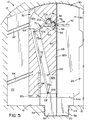
- the partition panels 32, 34 are moved laterally inwardly relative to the fuselage 12, and particularly relative to the aisle floor portion 20, and also slightly vertically upward to again accommodate for the round cross-section of the fuselage 12. More specifically, and as best shown in FIG. 5 with regard to the partition panel 32, the partition panels 32, 34 can be arranged on tracks 62, 64 and movement of the panels occurs slightly vertically in addition to laterally (i.e., movement within the fuselage 12 occurs slightly obliquely) to accommodate the circular shape of the fuselage 12.
- the tracks 62, 64 can be fixedly mounted on the bulkhead 22.
- the fuselage 12 can include recesses for accommodating the partition panels 32, 34 when in the respective open positions.
- the door assembly 30 additionally includes first and second descender panels 36, 38 moveably associated respectively with the first and second partition panels 32, 34 for closing an aisle opening 40 defined below the partition panels 32, 34 when the partition panels 32, 34 are closed together. More particularly, the aisle opening 40 is defined immediately above the aisle floor portion 20 and laterally between vertical floor portions 42, 44 extending from the aisle floor portion 20, respectively, to the seating area floor portions 16, 18.
- the first descender panel 36 is slidably mounted or secured on the first partition panel 32 and the second descender panel 38 is slidably mounted or secured on the second partition panel 34.
- the first descender panel 36 is moveably secured to a lower end 32a of the first partition panel 32 and the second descender panel 38 is moveably secured to a lower end 34a of the second partition panel 34.
- Both descender panels 36, 38 can close the aisle opening selectively and independently.
- the aisle opening 40 is closed up in addition to other apertures being closed up between the fuselage 12 and the partition panels 30, 32 because of the shape of the partition panels 32, 34 and the descender panels fits to the inner shape of the fuselage 12.
- each of the descender panels 34, 36 can be complementarily shaped to fit a shape of the aisle opening 40 within the fuselage 40. That is, no clearance gaps are provided about an entire periphery of the descender panels 34, 36 and the periphery of each descender panel 34, 36 closely follows the contours of the aisle floor portion 20 and the vertical floor portions 42, 44.
- the door assembly 30 additionally includes first and second actuating handles 50, 52 rotatably mounted respectively on the first and second partition panels 32, 34.
- first handle 50 is operatively connected to the first descender panel 36 through a first link mechanism 54 to translate rotation of the first handle 50 into vertical movement (e.g., vertical linear movement) of the first descender panel 36.
- second handle 52 is operatively connected to the descender panel 38 through a second link mechanism 56 to translate rotation of the second handle 52 into vertical movement (e.g., vertical linear movement) of the second descender panel 38.
- the door assembly 30 can further include first and second trimming edges 58, 60 mounted respectively on inside lateral edges 32b, 34b of the first and second partition panels 32, 34.
- Each of the first and second trimming edges 58, 60 can define a track that guides movement of a corresponding one of the first and second descender panels 36, 38 (e.g., linearly up and down).
- the track will be described in further detail below.
- the descender panels 36, 38 do not interfere with one another when moving between the deployed and the retracted positions due to their respective linear paths of movement, particularly linearly up and down in the illustrated embodiment.
- the first and second handles 50, 52 are independently rotatable between first rotatable positions (shown in FIG. 1 ) and second rotatable positions (shown in FIGS. 3 and 4 ).
- the first rotatable positions include orienting the handles 50, 52 horizontally and the second rotatable positions include orienting the handles 50, 52 vertically, though this is not required.
- the first and second handles 50, 52 can start from horizontally oriented positions of FIG. 1 so that the handles 50, 52 are collinear with one another and then rotated to the vertically oriented positions of FIGS. 3 and 4 so that the handles 50, 52 are parallel with and spaced apart from one another.
- the first rotatable positions for the handles 50, 52 correspond to deployed positions for the first and second descender panels 36, 38
- the second rotatable positions for the handles 50, 52 correspond to retracted positions for the first and second descender panels 36, 38.
- the first and second mechanisms 54, 56 pull the first and second descender panels 36, 38 upward (shown in FIG. 2 ) and the first and the second partition panels 32, 34 can be moved laterally toward their respective open positions (shown in FIG. 3 and FIG. 4 ).
- the handles 50, 52 could start in vertical positions when the descender panels 36, 38 are deployed or some other first angular orientation and could be moved to horizontal positions when the descender panels 36, 38 are retracted or to some other second angular orientation).
- handles corresponding to the handles 50, 52 can also be provided a reverse side of the partition panels 32, 34 to allow operation of the partition panels 32, 34 from either side (e.g., a cabin side and a lavatory side of the partition panels 32, 34).
- the first partition panel 32 is slidably mounted on the track members 62, 64 for lateral sliding movement across the fuselage 12.
- the track members 62, 64 are arranged to allow sliding movement both laterally and slightly vertically. Accordingly, when the first partition panel 32 is moved from the closed position to the open position, the first partition panel 32 moves laterally outwardly and slightly vertically downwardly, as guided by the track members 62, 64.
- the first link mechanism 54 operatively connects the actuating handle 50 and the descender panel 36 such that rotation of the handle 50 is translated by the first link mechanism 54 to sliding movement of the descender panel 36 (e.g., vertically or up and down in the figures). More particularly, the handle 50 is operatively connected to the descender panel 36 through the first link mechanism 54 such that rotation of the handle 50 is translated into movement of the descender panel 36 to move the descender panel 36 between the retracted position and the deployed position. In the illustrated embodiment, the first link mechanism 54 is received within a cavity 32c defined by the first partition panel 32. More particularly, and with brief reference to FIG.
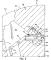
- the first partition panel 32 can be formed as a core member 32e in which the cavity 32c is defined, particularly in one side thereof, that houses or accommodates the first link mechanism 54 and an outer plate 32f that overlays the core member 32e on the side in which the cavity 32c is defined for closing the cavity 32c and covering the first link mechanism 54 (i.e., the first link mechanism 54 is not visible in the illustrated embodiment).
- the thickness of the core panel 32f can be relatively thin and thus the cavity 32e, which has a depth less than a thickness of the core panel 32e can be formed as a thin hollow.
- the link mechanism 54 can include a rocker arm link 70 having a first end 70a, a second end 70b and a fixed pivot axis or location 70c, wherein the rocker arm link 70 is fixably and pivotably connected to the partition panel 32, and an elongated link 72 having a first end 72a and a second end 72b.
- the first end 72a of the elongated link 72 is rotatably connected to the second end 70b of the rocker arm link 70 and the second end 72b of the elongated link 72 is rotatably connected to the descender panel 36.
- the first end 70a of the rocker arm link 70 is operatively connected to the handle 50 such that rotation of the handle 50 rotates the rocker arm link 70 about the fixed pivot location 70c to thereby vertically move (and only linearly move in the illustrated embodiment) the elongated link 72 and the descender panel 36 connected thereto.
- the link mechanism 54 can further include a floating link 74 having a first end 74a rotatably connected to the handle 50 such that rotation of the handle 50 moves the first end 74a of the floating link 74, and a second end 74b rotatably connected to the first end 70a of the rocker arm link 70 to transmit rotational movement of the handle 50 into rotational movement of the rocker arm link 70 about the fixed pivot point 70c.
- the link mechanism 54 can still further include a link driver 76 fixedly mounted or secured to the handle 50 for pivotal rotation therewith.
- the first end 74a of the floating link 74 is rotatably connected to a distal 76a of the link driver 76.
- the link driver 76 is a link that projects or extends from the handle 50 and has the distal end 76a spaced apart from a pivot axis or location 78 of the handle 50 (i.e., the pivotal location 78 being the location at which the handle 50 is rotatably mounted to the partition panel 32).
- the handle 50 is rotatable between the first rotatable position (shown in FIGS. 5 and 7 ) corresponding to the deployed position of the first descender panel 36 and the second rotatable position (shown in FIGS. 6 and 9 ) corresponding to the retracted position of the first descender panel 36.
- the handle 50 is arranged so as to be horizontal when in the first rotatable position and is arranged to be vertical when in the second rotatable position, though this is not required and other angular orientations can be used for each of the first and second rotatable positions.
- At least one magnet (e.g., magnet 88 and/or 90) can be arranged on the partition panel 32 so that the first link mechanism 54, and particularly the link driver 76 thereof, moves relative to the at least one magnet 88 and/or 90 as the handle 50 is rotated and the first link mechanism 54 moves due to such handle rotation.
- the link driver 76 can be arranged so as to be aligned with the at least one magnet (e.g., magnet 88 and/or 90) for magnetic holding by the at least one magnet when the first descender panel 36 is in at least one of the retracted or the deployed position.
- the link driver 76 is formed of a magnetically attractive material (e.g., steel) and the first partition panel 32 includes the first magnet 88 and the second magnet 90.
- the link driver 76 moves relative to the first and second magnets 88, 90 as the handle 50 is rotated and the link assembly 54 moves due to such handle rotation.
- the first magnet 88 is arranged such that the first magnet 88 is aligned with the link driver 76 when the descender panel 36 is in the deployed position of FIG. 5 .
- the second magnet 90 is arranged such that the second magnet 90 is aligned with the link driver 76 when the descender panel 36 is in the retracted position of FIG. 6 and a magnetic attraction between the second magnet 90 and the link driver 76 holds the handle 50 in the second rotatable position.
- the magnets 88,90 also provide feedback regarding the position of the handle 50 when a user rotates the handle 50. More particularly, movement of the handle 50 into either the first or second rotatable position is confirmed to a user by the magnetic force between the first magnet 88 and the link driver 76 or between the second magnet 90 and the link driver 76.
- the magnets 88, 90 are high strength magnets that provide a suitable holding force when aligned or in registry with link driver 76 and/or provide a positive locking feel when the handle 50 is in one of the first or second rotatable positions (i.e., provide feedback to the operator of the handle 50).
- stops 92, 94 can be arranged on the partition panel 36, 38 to limit rotational travel of the handle 50.
- the stops 92, 94 can limit rotational movement of the handle 50 between the first and second rotatable positions and thus prevent rotatably movement of the handle 50 beyond the first and second rotatable positions.
- the stops are non-metallic (e.g., formed of plastic, resin, etc.) such that any sound created by the link driver 76 engaging or striking the stops 92, 94 and is reduced and/or minimized.
- a mounting bracket 96 can be fastened to the partition panel 32.
- the mounting bracket 96 can have the handle 50 rotatably mounted thereto at the pivot location 78.
- the rocker arm link 70 can be mounted to the bracket 96 at the fixed pivot location 70c.
- the first and second magnets 88, 90 can be disposed on the mounting bracket 96.
- the stops 92, 94 can be disposed on the mounting bracket 96.
- the bracket 96 can be fastened to the partition panel 32 using any suitable fasteners, e.g., bolts, rivets, etc.
- the trimming edge 58 covers the inside lateral edge 32b as best shown in FIGS. 8 and 10 . Additionally, and as mentioned, the trimming edge 58 defines the track in which the descender panel 36 moves, particularly the trimming edge 58 defines one side of the track in which the descender panel 36 moves.
- the partition panel 32, and particularly the rigid core panel 32e thereof, can additionally define a descender panel cavity 32d in the form of a thin hollow in which the descender panel 36 is received when in the retracted position.
- the partition panel 36 can further include a guide member 98 appropriately spaced laterally from the trimming edge 58. The guide member 98 can further define the track.
- the guide member 98 defines a second side of the track in which the descender panel 36 is received and guided for sliding movement (e.g., linearly in the illustrated embodiment). Accordingly, through the trimming edge 58 and the guide member 98, the partition panel 32 defines the track and the descender panel 36 is received in the track for guiding linear sliding movement of the descender panel 36 between the retracted and deployed positions.
- At least one magnet (e.g., first magnet 100 and/or second magnet 102) is disposed on the partition panel 32 and a magnetically attractive boss 104 disposed on the descender panel 36 for movement with the descender panel 36.
- the magnetically attractive boss 104 moves relative to the at least one magnet (e.g., first magnet 100 and/or second magnet 102) as the descender panel 36 moves between the retracted position and the deployed position.
- the magnetically attractive boss 104 is in registry with the at least one magnet (e.g., first magnet 100 and/or second magnet 102), and therefore restricted with the at lest one magnet, when the descender panel 36 is in at least one of the deployed position or the retracted position.
- the door assembly 30 includes both the first magnet 100 and the second magnet 102 on the descender panel 36, though only one magnet or no magnets could be employed.
- the magnetic attraction between the boss 104 and the first magnet 104 can hold the descender panel 36 in the retracted position.
- the magnetic attraction between the boss 104 and the second magnet 102 can hold the descender panel 36 in the deployed position.
- the positional relationship between the bulkhead 24 and the second partition panel 34 is illustrated and will now be described in particular detail.
- the details concerning the bulkhead 24 and the second partition panel 34 are applicable to the bulkhead 22 and the first partition panel 22 since these can be mirrored copies of one another.
- the bulkhead 24 can be formed of a pair of spaced apart panel members 24a, 24b defining a pocket 24c therebetween in which the second partition panel 34 is received when in the open position.
- the second partition panel 34 is sandwiched between the two panel members 24a, 24b.
- Track members for guiding movement of the second partition panel 34 (e.g., tracks members like the track members 62, 64 for the first partition panel 32) can be specifically mounted to the panel member 24b.
- the bulkhead panel 24a can include a cut-out edge 24d for accommodating the handle 52 when the second partition panel 34 is in the open position.
- the handle 50 can be rotated from the first rotatable position shown in FIGS. 5 and 7 approximately 90 degrees to the second rotatable position shown in FIGS. 6 and 9 .
- Rotation of the handle from the first rotatable position to the second rotatable position is transmitted and translated through the link mechanism, and particularly through the link driver 76, the floating link 74, the rocker arm link 70 and the elongated link 72, to vertical movement of the descender panel 36.
- movement of the handle 50 from the first rotatable position to the second rotatable position translates into vertical movement of the descender panel 36 from the deployed position to the retracted position.
- the descender panel 36 moves along the track defined by the trimming edge 58 and the guide member 98 disposed on or as part of the partition panel 32.
- the handle 50 is rotated a first rotatable direction (i.e., counterclockwise in FIG. 5 ), which causes the link driver 76 to likewise rotate in the first rotatable direction (i.e., counterclockwise in FIG. 5 ).
- Rotation of the link driver 76 is transmitted and reversed by the floating link 74 connecting the link driver 76 and the rocker arm link 70.
- the floating link 74 causes the rocker arm link 70 to rotate in a second rotatable direction (i.e., clockwise in FIG. 5 ) that is opposite the first rotatable direction such that the end 70b of the rocker arm 70 pivots from the lowered position shown in FIG. 5 to the elevated position shown in FIG. 6 .
- This change in elevation is transmitted to the descender panel 36 by the elongated link 72 so as to move the descender panel 36 from the deployed position of FIG. 5 to the retracted position of FIG. 6 .
- the track comprised of the trimming edge 58 and the guide member 98 maintains movement of the descender panel 36 only linearly, and particularly only linearly up and down in the illustrated embodiment.
- the descender panel 36 can be held in the deployed position by the magnets 86 and 90 being in registry with one another and/or the magnets 100, 102 being in registry with one another.
- the handle 50 is moved to the second rotatable position, the position of the handle 50 and the position of the descender panel 36 can be held by the magnets 86 and 90 and/or the magnets 100, 102 being in registry with one another.
- a further feature of the magnets is the provision of feedback to the user of or operator of the handle 50. Subsequently, the handle 50 can be returned by rotation back to the first rotatable position. Such movement is against transmitted and translated through the link mechanism 54, but in reverse so that the descender panel 36 moves from the retracted position back to the deployed position.
- the handle 50 is rotated in the second rotatable direction (i.e., clockwise in FIG. 6 ), which causes the link driver to likewise rotate in the second rotatable direction (i.e., clockwise in FIG. 6 ).
- Rotation of the link diver 76 is transmitted and reversed by the floating link 74 such that the floating link 74 causes the rocker arm link 70 to rotate in the first rotatable direction (i.e., counterclockwise in FIG. 6 ).
- the change is elevation is again transmitted to the descender panel 36 by the elongated link but this time to move the descender panel 36 from the retracted position of FIG. 6 to the deployed position of FIG. 5 .
- the track 58, 98 maintains movement of the descender panel only linearly (i.e.., up and down in the illustrated embodiment).
- the mechanical structure of the door assembly 30 is relatively simple and thus does not require a complex mechanism and/or require a large space to operate. It will be appreciated that various of the above-disclosed and other features and functions, or alternatives or varieties thereof, may be desirably combined into many other different systems or applications. Also that various presently unforeseen or unanticipated alternatives, modifications, variations or improvements therein may be subsequently made by those skilled in the art which are also intended to be encompassed by the following claims.
Landscapes
- Engineering & Computer Science (AREA)
- Aviation & Aerospace Engineering (AREA)
- Mechanical Engineering (AREA)
- Lock And Its Accessories (AREA)
- Vehicle Step Arrangements And Article Storage (AREA)
- Specific Sealing Or Ventilating Devices For Doors And Windows (AREA)
- Power-Operated Mechanisms For Wings (AREA)
Description
- Many aircrafts use one or more bulkheads (i.e., partitions) or curtains to screen a cabin. If an aircraft uses a bulkhead in its cabin, a door opening with a lateral slide type door could be provided in association with the bulkhead to allow passengers to get through the bulkhead. In many cases, the level of aisle way in a smaller aircraft (e.g., light jet) is lower than the level of a seating area floor because having a lower aisle way provides maximum headroom and is easier for passengers to move in the cabin. In this case, there will be a large opening at the bottom of the door due to the aisle way even if the doors are closed. To obstruct the large opening, descenders are sometimes used in some smaller aircraft in association with one or more slide type doors disposed laterally within the bulkhead of the aircraft. Such descenders are useful to preserve passengers' privacy and to reduce noise in the cabin. The descender can take the form of one or more panels that covers the large opening disposed below the slide type doors.
- For example, in one application, one or more bulkhead doors are provided to close an opening defined between a pair of spaced apart fixed solid bulkheads within the aircraft fuselage. The fuselage is generally circular in cross-section with the fixed solid bulkheads protruding radially inward from the fuselage. The one or more doors can close the door opening defined between the fixed solid bulkheads. Typically, this is done by employing sliding doors that converge together when closed from positions recessed within or adjacent the fixed solid bulkheads.
- Known descenders include so-called automatic rotary descenders. These are actuated mechanically when the door to which the descender is associated is slidably moved. For example, when the door is open, the descender rotates at the bottom of the door in a plane generally parallel with the door and opens the aisle opening automatically in response to the movement of the door; when the door is closed, the descender rotates at the bottom of the door again in the plan generally parallel with the door and closes the aisle opening automatically in response to the movement of the door.
- In one specific known automatic rotary style descender, the descender is forced to rotate by being pressed on a carpet edge provided or defining the aisle opening in response to the movement of the door when the door is opened. The descender is stored in the interspace of the door in response to the movement of the door. In another known arrangement, cables are used to rotate and store the descender in a particular path as the door is opened. These rotary arrangements are relatively complex and therefore expensive. In particular, there are often space restrictions and issues with reliability of deployment for the so-called automatic rotary style descenders. The rotating style requires significant amounts of space to store the descender in the door and the descenders require large gaps for clearance purposes because head of each descender is easy to interfere each other when they are rotating. This means that it is difficult to obstruct the opening of the aisle way tightly with the traditional automatic rotary style descenders. In addition, the cable actuated style easily jams or malfunctions and operation is not always smooth.
-
US 2009/078824 A1 discloses a partition assembly adapted to selectively separate a first space from a second space, said assembly comprising a wall portion defining an opening and a plurality of panels arranged in communication with said wall portion and each other to selectively cover said opening when said plurality of panels are in a fully extended position and to uncover said opening when said plurality of panels are in a retracted position. Said plurality of panels comprises at least one driving panel and at least one following panel coupled such that movement of said at least one driving panel causes movement of said at least one following panel. Moreover, said at least one driving panel moves linearly to cause said at least one following panel to move linearly and rotationally. - According to the invention, a door assembly for an aircraft comprises: a partition panel disposed in use laterally within a fuselage of the aircraft; a descender panel movably secured to a lower end of the partition panel for selectively closing an aisle opening defined below the partition panel; and a handle disposed on the partition panel and operatively connected to descender panel through a link mechanism such that rotation of the handle is translated into linear movement of the descender panel to move the descender panel between a retracted position and a deployed position, wherein the link mechanism includes: a rocker arm link having a first end, a second end and a fixed pivot location wherein the rocker arm link is fixedly and pivotally connected to the partition panel; and an elongated link having a first end and a second end, wherein a first end of the elongated link is rotatably connected to the second end of the rocker arm link and a second end of the elongated link is rotatably connected to the descender panel, and wherein the first end of the rocker arm link is operatively connected to the handle such that rotation of the handle rotates the rocker arm link about the fixed pivot location to thereby vertically move the elongated link and the descender panel connected thereto.
- Preferred embodiments of the invention are described in the dependent claims.
-
-
FIG. 1 is a schematic cross-sectional view of an aircraft fuselage having a door assembly with slidably disposed partition panels and descender panels shown in respective deployed positions according one exemplary embodiment. -
FIG. 2 is a schematic cross-sectional view similar toFIG. 1 but showing the descender panels moving toward respective retracted positions. -
FIG. 3 is a schematic cross-sectional view similar toFIGS. 1 and 2 but showing the partition panels slidably moving apart from one another to provide access through a door opening. -
FIG. 4 is a schematic cross-sectional view similar toFIGS. 1-3 but showing the partition panels in fully opened positions. -
FIG. 5 is another schematic cross-sectional view but showing one of the partition panels in cross-section to reveal a link mechanism operatively connecting a handle of the partition panel to the descender panel. -
FIG. 6 is a view similar toFIG. 5 but showing the descender in the retracted position and the partition panel in the slide open position. -
FIG. 7 is a partial enlarged cross-sectional view of the partition panel ofFIGS. 5 and6 showing the link mechanism when the handle is rotated to move the descender panel into the retracted position. -
FIG. 8 is a partial enlarged cross-sectional view showing the descender panel moving within a track defined by the partition panel ofFIGS. 5-7 . -
FIG. 9 is a partial enlarged cross-sectional view similar toFIG. 7 but showing the handle in the first rotatable position wherein the descender panel is in the retracted position. -
FIG. 10 is a partial enlarged cross-sectional view similar toFIG. 8 but showing the descender panel in the retracted position. -
FIG. 11 is a partial perspective view of one of the partition panels slidably received within a pocket formed in a bulkhead of the aircraft fuselage. - Referring now to the drawings wherein the showings are for purposes of illustrating one or more exemplary embodiments and not for purposes of limiting same,
FIGS. 1-4 illustrate anaircraft 10 having anaircraft fuselage 12 with a generally circular cross-section. Within thefuselage 12, a cabin area 14 (FIGS. 3 and 4 ) is defined. As shown, a lower extent of thecabin area 14 can be defined by seatingarea floor portions aisle floor portion 20 disposed between the seatingarea floor portions aisle floor portion 20 is disposed at an elevation below the seatingarea floor portions cabin area 14 at the location of theaisle floor portion 20. In the illustrated location within thefuselage 12, fixedbulkheads area floor portions 16, 18) towards a central region of the cabin area 14 (i.e., disposed above the aisle floor portion 20) from lateral sides of thefuselage 12 to define a doorway orpassageway 26 aligned with theaisle floor portion 20. In one example, thefixed bulkheads - For closing the
passageway 26, anaircraft door assembly 30 is provided with first and second rigid partitions orpartition panels partition panels fuselage 12 for sliding movement toward one another when thepartition panels FIG. 1 ) and sliding movement away from one another when thepartition panels partition panels cabin area 14 defined by the fuselage 12 (i.e., generally perpendicular relative to an axis of the fuselage 12). Accordingly, and is known and understood by those skilled in the art, thepartition panels fuselage 12 for lateral movement (and slight vertical movement) relative to thefuselage 12 between respective closed positions (shown inFIG. 1 ) and respective open positions (shown inFIG. 4 ). When thedoor assembly 30, and particularly the partition panels thereof, are displaced toward the open positions, thepartition panels aisle floor portion 20, and also slightly vertically downward to accommodate for the round cross-section of thefuselage 12. - On the other hand, when the
door assembly 30, and particularly thepartition panels partition panels fuselage 12, and particularly relative to theaisle floor portion 20, and also slightly vertically upward to again accommodate for the round cross-section of thefuselage 12. More specifically, and as best shown inFIG. 5 with regard to thepartition panel 32, thepartition panels tracks fuselage 12 occurs slightly obliquely) to accommodate the circular shape of thefuselage 12. Thetracks bulkhead 22. As shown schematically in dashed lines inFIGS. 1-4 , thefuselage 12 can include recesses for accommodating thepartition panels - The
door assembly 30 additionally includes first andsecond descender panels second partition panels aisle opening 40 defined below thepartition panels partition panels aisle opening 40 is defined immediately above theaisle floor portion 20 and laterally betweenvertical floor portions aisle floor portion 20, respectively, to the seatingarea floor portions first descender panel 36 is slidably mounted or secured on thefirst partition panel 32 and thesecond descender panel 38 is slidably mounted or secured on thesecond partition panel 34. Accordingly, and as shown, thefirst descender panel 36 is moveably secured to alower end 32a of thefirst partition panel 32 and thesecond descender panel 38 is moveably secured to alower end 34a of thesecond partition panel 34. Bothdescender panels partition panels aisle opening 40 is closed up in addition to other apertures being closed up between thefuselage 12 and thepartition panels partition panels fuselage 12. As shown, each of thedescender panels fuselage 40. That is, no clearance gaps are provided about an entire periphery of thedescender panels descender panel aisle floor portion 20 and thevertical floor portions - The
door assembly 30 additionally includes first and second actuating handles 50, 52 rotatably mounted respectively on the first andsecond partition panels first handle 50 is operatively connected to thefirst descender panel 36 through afirst link mechanism 54 to translate rotation of thefirst handle 50 into vertical movement (e.g., vertical linear movement) of thefirst descender panel 36. Likewise, thesecond handle 52 is operatively connected to thedescender panel 38 through asecond link mechanism 56 to translate rotation of thesecond handle 52 into vertical movement (e.g., vertical linear movement) of thesecond descender panel 38. Additionally, and as will also be described in more detail below, thedoor assembly 30 can further include first and second trimming edges 58, 60 mounted respectively on insidelateral edges second partition panels second descender panels 36, 38 (e.g., linearly up and down). The track will be described in further detail below. Advantageously, and as will also be described in more detail below, thedescender panels - The first and
second handles FIG. 1 ) and second rotatable positions (shown inFIGS. 3 and 4 ). In the illustrated embodiment, the first rotatable positions include orienting thehandles handles second handles FIG. 1 so that thehandles FIGS. 3 and 4 so that thehandles handles second descender panels handles second descender panels - When the
handles second mechanisms second descender panels FIG. 2 ) and the first and thesecond partition panels FIG. 3 and FIG. 4 ). It is to be appreciated by those skilled in the art that other orientations for thehandles handles descender panels descender panels handles partition panels partition panels partition panels 32, 34). - With reference now to
FIGS. 5-10 , thefirst partition panel 32, thefirst descender 36, thehandle 50 and thelink mechanism 54 associated with thefirst partition panel 32 will be described in particular detail. As will be appreciated and understood by those skilled in the art, thesecond partition panel 34, thesecond descender 38, thesecond handle 52 and thesecond link mechanism 56 can be mirrored copies and thus include corresponding components and operate the same as thefirst partition panel 32, thefirst descender 36, thefirst handle 50 and thefirst link mechanism 54. As shown inFIG. 5 , thefirst partition panel 32 is slidably mounted on thetrack members fuselage 12. In particular, thetrack members first partition panel 32 is moved from the closed position to the open position, thefirst partition panel 32 moves laterally outwardly and slightly vertically downwardly, as guided by thetrack members - The
first link mechanism 54 operatively connects theactuating handle 50 and thedescender panel 36 such that rotation of thehandle 50 is translated by thefirst link mechanism 54 to sliding movement of the descender panel 36 (e.g., vertically or up and down in the figures). More particularly, thehandle 50 is operatively connected to thedescender panel 36 through thefirst link mechanism 54 such that rotation of thehandle 50 is translated into movement of thedescender panel 36 to move thedescender panel 36 between the retracted position and the deployed position. In the illustrated embodiment, thefirst link mechanism 54 is received within acavity 32c defined by thefirst partition panel 32. More particularly, and with brief reference toFIG. 7 , thefirst partition panel 32 can be formed as acore member 32e in which thecavity 32c is defined, particularly in one side thereof, that houses or accommodates thefirst link mechanism 54 and anouter plate 32f that overlays thecore member 32e on the side in which thecavity 32c is defined for closing thecavity 32c and covering the first link mechanism 54 (i.e., thefirst link mechanism 54 is not visible in the illustrated embodiment). The thickness of thecore panel 32f can be relatively thin and thus thecavity 32e, which has a depth less than a thickness of thecore panel 32e can be formed as a thin hollow. - The
link mechanism 54 can include arocker arm link 70 having afirst end 70a, asecond end 70b and a fixed pivot axis orlocation 70c, wherein therocker arm link 70 is fixably and pivotably connected to thepartition panel 32, and anelongated link 72 having afirst end 72a and asecond end 72b. Thefirst end 72a of theelongated link 72 is rotatably connected to thesecond end 70b of therocker arm link 70 and thesecond end 72b of theelongated link 72 is rotatably connected to thedescender panel 36. Thefirst end 70a of therocker arm link 70 is operatively connected to thehandle 50 such that rotation of thehandle 50 rotates therocker arm link 70 about the fixedpivot location 70c to thereby vertically move (and only linearly move in the illustrated embodiment) theelongated link 72 and thedescender panel 36 connected thereto. - The
link mechanism 54 can further include a floatinglink 74 having afirst end 74a rotatably connected to thehandle 50 such that rotation of thehandle 50 moves thefirst end 74a of the floatinglink 74, and asecond end 74b rotatably connected to thefirst end 70a of therocker arm link 70 to transmit rotational movement of thehandle 50 into rotational movement of therocker arm link 70 about the fixedpivot point 70c. Thelink mechanism 54 can still further include alink driver 76 fixedly mounted or secured to thehandle 50 for pivotal rotation therewith. Thefirst end 74a of the floatinglink 74 is rotatably connected to a distal 76a of thelink driver 76. In the illustrated embodiment, thelink driver 76 is a link that projects or extends from thehandle 50 and has thedistal end 76a spaced apart from a pivot axis orlocation 78 of the handle 50 (i.e., thepivotal location 78 being the location at which thehandle 50 is rotatably mounted to the partition panel 32). - As mentioned, the
handle 50 is rotatable between the first rotatable position (shown inFIGS. 5 and7 ) corresponding to the deployed position of thefirst descender panel 36 and the second rotatable position (shown inFIGS. 6 and9 ) corresponding to the retracted position of thefirst descender panel 36. In the illustrated embodiment, thehandle 50 is arranged so as to be horizontal when in the first rotatable position and is arranged to be vertical when in the second rotatable position, though this is not required and other angular orientations can be used for each of the first and second rotatable positions. At least one magnet (e.g.,magnet 88 and/or 90) can be arranged on thepartition panel 32 so that thefirst link mechanism 54, and particularly thelink driver 76 thereof, moves relative to the at least onemagnet 88 and/or 90 as thehandle 50 is rotated and thefirst link mechanism 54 moves due to such handle rotation. Thelink driver 76 can be arranged so as to be aligned with the at least one magnet (e.g.,magnet 88 and/or 90) for magnetic holding by the at least one magnet when thefirst descender panel 36 is in at least one of the retracted or the deployed position. - More particularly, in the illustrated embodiment, the
link driver 76 is formed of a magnetically attractive material (e.g., steel) and thefirst partition panel 32 includes thefirst magnet 88 and thesecond magnet 90. Thelink driver 76 moves relative to the first andsecond magnets handle 50 is rotated and thelink assembly 54 moves due to such handle rotation. Thefirst magnet 88 is arranged such that thefirst magnet 88 is aligned with thelink driver 76 when thedescender panel 36 is in the deployed position ofFIG. 5 . Thesecond magnet 90 is arranged such that thesecond magnet 90 is aligned with thelink driver 76 when thedescender panel 36 is in the retracted position ofFIG. 6 and a magnetic attraction between thesecond magnet 90 and thelink driver 76 holds thehandle 50 in the second rotatable position. - In addition to the
magnet 90 applying a holding force that maintains thedescender panel 36 in the retracted position against the urging of gravity and/or any bias provided by thelink mechanism 54, themagnets handle 50 when a user rotates thehandle 50. More particularly, movement of thehandle 50 into either the first or second rotatable position is confirmed to a user by the magnetic force between thefirst magnet 88 and thelink driver 76 or between thesecond magnet 90 and thelink driver 76. In one embodiment, themagnets link driver 76 and/or provide a positive locking feel when thehandle 50 is in one of the first or second rotatable positions (i.e., provide feedback to the operator of the handle 50). - In addition to the magnets or without the magnets, stops 92, 94 can be arranged on the
partition panel handle 50. In particular, thestops handle 50 between the first and second rotatable positions and thus prevent rotatably movement of thehandle 50 beyond the first and second rotatable positions. In one embodiment, the stops are non-metallic (e.g., formed of plastic, resin, etc.) such that any sound created by thelink driver 76 engaging or striking thestops - A mounting
bracket 96 can be fastened to thepartition panel 32. The mountingbracket 96 can have thehandle 50 rotatably mounted thereto at thepivot location 78. Likewise, therocker arm link 70 can be mounted to thebracket 96 at the fixedpivot location 70c. Additionally, the first andsecond magnets bracket 96. Likewise, thestops bracket 96. Thebracket 96 can be fastened to thepartition panel 32 using any suitable fasteners, e.g., bolts, rivets, etc. - The trimming
edge 58 covers the insidelateral edge 32b as best shown inFIGS. 8 and10 . Additionally, and as mentioned, the trimmingedge 58 defines the track in which thedescender panel 36 moves, particularly the trimmingedge 58 defines one side of the track in which thedescender panel 36 moves. Thepartition panel 32, and particularly therigid core panel 32e thereof, can additionally define adescender panel cavity 32d in the form of a thin hollow in which thedescender panel 36 is received when in the retracted position. Thepartition panel 36 can further include aguide member 98 appropriately spaced laterally from the trimmingedge 58. Theguide member 98 can further define the track. Particularly theguide member 98 defines a second side of the track in which thedescender panel 36 is received and guided for sliding movement (e.g., linearly in the illustrated embodiment). Accordingly, through the trimmingedge 58 and theguide member 98, thepartition panel 32 defines the track and thedescender panel 36 is received in the track for guiding linear sliding movement of thedescender panel 36 between the retracted and deployed positions. - In the illustrated embodiment, at least one magnet (e.g.,
first magnet 100 and/or second magnet 102) is disposed on thepartition panel 32 and a magneticallyattractive boss 104 disposed on thedescender panel 36 for movement with thedescender panel 36. The magneticallyattractive boss 104 moves relative to the at least one magnet (e.g.,first magnet 100 and/or second magnet 102) as thedescender panel 36 moves between the retracted position and the deployed position. The magneticallyattractive boss 104 is in registry with the at least one magnet (e.g.,first magnet 100 and/or second magnet 102), and therefore restricted with the at lest one magnet, when thedescender panel 36 is in at least one of the deployed position or the retracted position. More particularly, in the illustrated embodiment, thedoor assembly 30 includes both thefirst magnet 100 and thesecond magnet 102 on thedescender panel 36, though only one magnet or no magnets could be employed. The magnetic attraction between theboss 104 and thefirst magnet 104 can hold thedescender panel 36 in the retracted position. Likewise, the magnetic attraction between theboss 104 and thesecond magnet 102 can hold thedescender panel 36 in the deployed position. - With additional reference to
FIG. 11 , the positional relationship between thebulkhead 24 and thesecond partition panel 34 is illustrated and will now be described in particular detail. As will be appreciated and understood by those skilled in the art, the details concerning thebulkhead 24 and thesecond partition panel 34 are applicable to thebulkhead 22 and thefirst partition panel 22 since these can be mirrored copies of one another. As shown, thebulkhead 24 can be formed of a pair of spaced apartpanel members 24a, 24b defining apocket 24c therebetween in which thesecond partition panel 34 is received when in the open position. Thus, thesecond partition panel 34 is sandwiched between the twopanel members 24a, 24b. Track members (not shown) for guiding movement of the second partition panel 34 (e.g., tracks members like thetrack members bulkhead panel 24a can include a cut-outedge 24d for accommodating thehandle 52 when thesecond partition panel 34 is in the open position. - In operation, the
handle 50 can be rotated from the first rotatable position shown inFIGS. 5 and7 approximately 90 degrees to the second rotatable position shown inFIGS. 6 and9 . Rotation of the handle from the first rotatable position to the second rotatable position is transmitted and translated through the link mechanism, and particularly through thelink driver 76, the floatinglink 74, therocker arm link 70 and theelongated link 72, to vertical movement of thedescender panel 36. In particular, movement of thehandle 50 from the first rotatable position to the second rotatable position translates into vertical movement of thedescender panel 36 from the deployed position to the retracted position. Particularly, thedescender panel 36 moves along the track defined by the trimmingedge 58 and theguide member 98 disposed on or as part of thepartition panel 32. - More specifically, in the illustrated embodiment, the
handle 50 is rotated a first rotatable direction (i.e., counterclockwise inFIG. 5 ), which causes thelink driver 76 to likewise rotate in the first rotatable direction (i.e., counterclockwise inFIG. 5 ). Rotation of thelink driver 76 is transmitted and reversed by the floatinglink 74 connecting thelink driver 76 and therocker arm link 70. Accordingly, the floatinglink 74 causes therocker arm link 70 to rotate in a second rotatable direction (i.e., clockwise inFIG. 5 ) that is opposite the first rotatable direction such that theend 70b of therocker arm 70 pivots from the lowered position shown inFIG. 5 to the elevated position shown inFIG. 6 . This change in elevation is transmitted to thedescender panel 36 by theelongated link 72 so as to move thedescender panel 36 from the deployed position ofFIG. 5 to the retracted position ofFIG. 6 . The track comprised of the trimmingedge 58 and theguide member 98 maintains movement of thedescender panel 36 only linearly, and particularly only linearly up and down in the illustrated embodiment. - The
descender panel 36 can be held in the deployed position by themagnets 86 and 90 being in registry with one another and/or themagnets handle 50 is moved to the second rotatable position, the position of thehandle 50 and the position of thedescender panel 36 can be held by themagnets 86 and 90 and/or themagnets handle 50. Subsequently, thehandle 50 can be returned by rotation back to the first rotatable position. Such movement is against transmitted and translated through thelink mechanism 54, but in reverse so that thedescender panel 36 moves from the retracted position back to the deployed position. - More particularly, in the illustrated embodiment, the
handle 50 is rotated in the second rotatable direction (i.e., clockwise inFIG. 6 ), which causes the link driver to likewise rotate in the second rotatable direction (i.e., clockwise inFIG. 6 ). Rotation of thelink diver 76 is transmitted and reversed by the floatinglink 74 such that the floatinglink 74 causes therocker arm link 70 to rotate in the first rotatable direction (i.e., counterclockwise inFIG. 6 ). This results in theend 70b moving from the elevated position ofFIG. 6 to the lowered position ofFIG. 5 . The change is elevation is again transmitted to thedescender panel 36 by the elongated link but this time to move thedescender panel 36 from the retracted position ofFIG. 6 to the deployed position ofFIG. 5 . Again, thetrack - Advantageously, the mechanical structure of the
door assembly 30 is relatively simple and thus does not require a complex mechanism and/or require a large space to operate. It will be appreciated that various of the above-disclosed and other features and functions, or alternatives or varieties thereof, may be desirably combined into many other different systems or applications. Also that various presently unforeseen or unanticipated alternatives, modifications, variations or improvements therein may be subsequently made by those skilled in the art which are also intended to be encompassed by the following claims.
Claims (11)
- A door assembly (30) for an aircraft (10), comprising:a partition panel (32) disposed in use laterally within a fuselage (12) of the aircraft (10);a descender panel (36) movably secured to a lower end (32a) of the partition panel (32) for selectively closing an aisle opening (40) defined below the partition panel (32); anda handle (50) disposed on the partition panel (32) and operatively connected to descender panel (36) through a link mechanism (54) such that rotation of the handle (50) is translated into linear movement of the descender panel (36) to move the descender panel (36) between a retracted position and a deployed position,wherein the link mechanism (54) includes:a rocker arm link (70) having a first end (70a), a second end (70b) and a fixed pivot location (70c) wherein the rocker arm link (70) is fixedly and pivotally connected to the partition panel (32); andan elongated link (72) having a first end (72a) and a second end (72b), wherein a first end (72a) of the elongated link (72) is rotatably connected to the second end (70b) of the rocker arm link (70) and a second end (72b) of the elongated link (72) is rotatably connected to the descender panel (36), andwherein the first end (70a) of the rocker arm link (70) is operatively connected to the handle (50) such that rotation of the handle (50) rotates the rocker arm link (70) about the fixed pivot location (70) to thereby vertically move the elongated link (72) and the descender panel (36) connected thereto.
- The door assembly (30) of claim 1,
wherein the partition panel (32) defines a track and the descender panel (36) is received in the track for linear guiding sliding movement of the descender panel (36) between the retracted and deployed positions. - The door assembly (30) of claim 2,
wherein the partition panel (32) has an inside lateral edge (32b) and the door assembly (30) includes a trimming edge (58) covering the inside lateral edge (32b) and defining the track, and wherein the link mechanism (54) is housed within a cavity defined by the partition panel (32),
and wherein, preferably, the partition panel (52) includes a guide member (98) spaced laterally from the trimming edge (58), the guide member (98) further defining the track. - The door assembly (30) of claim 1,
wherein the link mechanism (54) further includes:
a floating link (74) having a first end (74a) rotatably connected to the handle (50) such that rotation of the handle (50) moves the first end (74a) of the floating link (74), and a second end (74b) rotatably connected to the first end (70a) of the rocker arm link (70) to transmit rotational movement of the handle (50) into rotational movement of the rocker arm link (70) about the fixed pivot point (70c). - The door assembly (30) of claim 4,
wherein the link mechanism (54) further includes:
a link driver (76) fixedly mounted to the handle (50) for corotation therewith, the first end of the floating link (74) rotatably connected to a distal end (76a) of the link driver (76). - The door assembly (30) of claim 5,
wherein the handle (50) is rotatable between a first rotatable position corresponding to the deployed position of the descender panel (36) and a second rotatable position corresponding to the retracted position of the descender panel (36). - The door assembly (30) of claim 6,
wherein the link driver (76) is formed of a magnetically attractive material and the partition panel (32) includes a first magnet (88) and a second magnet (90), the first magnet (88) arranged such that the first magnet (88) is aligned with the link driver (76) when the descender panel (36) is in the deployed position, the second magnet (90) arranged such that the second magnet (90) is aligned with the link driver (76) when the descender panel (36) is in the retracted position and a magnetic attraction between the second magnet (90) and the link driver (76) holds the handle (50) in the second rotatable position. - The door assembly (30) of claim 6,
wherein nonmetallic stops (92, 94) are arranged on the partition panel (36) to limit rotational travel of the handle (50) to movement beyond the first and second rotatable positions. - The door assembly (30) of claim 1,
further including at least one magnet (88) arranged on the partition panel (32), the link mechanism (54) moving relative to the at least one magnet (88) as the handle (50) is rotated and the link mechanism (54) moves due to such handle rotation, a link driver (76) of the link mechanism (54) aligned with the at least one magnet (88) for magnetic holding by the at least one magnet (88) when the descender panel (36) is in at least one of the retracted position or the deployed position. - The door assembly (30) of claim 1,
further including at least one magnet (100) disposed on the partition panel (32) and a magnetically attractive boss (104) disposed on the descender panel (36) for movement with the descender panel (36), the magnetically attractive boss (104) moving relative to the at least one magnet (100) as the descender panel (36) moves between the retracted position and the deployed position, the magnetically attractive boss (104) in registry with the at least one magnet (100) when the descender panel (36) is in at least one of the deployed position or the retracted position. - The door assembly (30) of claim 1,
wherein a bulkhead (22, 24) is arranged within the fuselage (12), the partition panel (32) in use slidably secured to the bulkhead (22, 24) via track members for lateral movement relative to the bulkhead (22, 24) and the fuselage (12) between an open position wherein the partition panel (32) is retracted radially outwardly relative to the fuselage (12) and a closed position wherein the partition panel (32) is projected radially inwardly relative to the fuselage (12), the partition panel (32) also moving slightly vertically when moved between the open position and the closed position to accommodate a round cross-section of the fuselage (12),
and wherein, preferably, the partition panel (32) is a first partition panel and the door assembly (30) includes a second partition panel (34) in use disposed laterally within a fuselage (12) of the aircraft (10) for sliding movement toward one another when the first and second partition panels (32, 34) are moved to respective closed positions and sliding movement away from one another when the first and second partition panels (32, 34) are moved to respective open positions.
Applications Claiming Priority (2)
| Application Number | Priority Date | Filing Date | Title |
|---|---|---|---|
| US13/664,215 US10023288B2 (en) | 2012-10-30 | 2012-10-30 | Aircraft door mechanism with handle actuated descender |
| PCT/US2013/062754 WO2014070353A1 (en) | 2012-10-30 | 2013-09-30 | Aircraft door mechanism with handle actuated descender |
Publications (3)
| Publication Number | Publication Date |
|---|---|
| EP2920067A1 EP2920067A1 (en) | 2015-09-23 |
| EP2920067A4 EP2920067A4 (en) | 2016-06-08 |
| EP2920067B1 true EP2920067B1 (en) | 2018-05-30 |
Family
ID=50546109
Family Applications (1)
| Application Number | Title | Priority Date | Filing Date |
|---|---|---|---|
| EP13850470.9A Not-in-force EP2920067B1 (en) | 2012-10-30 | 2013-09-30 | Aircraft door mechanism with handle actuated descender |
Country Status (7)
| Country | Link |
|---|---|
| US (1) | US10023288B2 (en) |
| EP (1) | EP2920067B1 (en) |
| JP (1) | JP6251278B2 (en) |
| AU (1) | AU2013338518B2 (en) |
| BR (1) | BR112015009484B1 (en) |
| CA (1) | CA2888164C (en) |
| WO (1) | WO2014070353A1 (en) |
Families Citing this family (10)
| Publication number | Priority date | Publication date | Assignee | Title |
|---|---|---|---|---|
| US10829195B2 (en) * | 2014-05-12 | 2020-11-10 | Bombardier Inc. | Bulkhead assembly with pocket door for aircraft interior |
| US10029778B2 (en) | 2015-05-22 | 2018-07-24 | Gulfstream Aerospace Corporation | Aircraft door with compressible header |
| EP3168138B1 (en) * | 2015-11-10 | 2018-06-06 | Airbus Operations GmbH | Aircraft door assembly |
| US10160532B2 (en) * | 2016-01-21 | 2018-12-25 | Gulfstream Aerospace Corporation | Aircraft door with retractable header |
| US9919767B2 (en) * | 2016-07-21 | 2018-03-20 | Protomet Corporation | Wind block door for companionway hatch |
| DE102016013504B4 (en) * | 2016-11-11 | 2022-11-24 | Diehl Aviation Laupheim Gmbh | Partition wall for a passenger cabin of a passenger aircraft, partition wall arrangement and fin module for the partition wall |
| US10865599B2 (en) * | 2017-06-29 | 2020-12-15 | The Boeing Company | Seal assembly for a galley door of a galley and method of assembling a galley with a seal assembly |
| US11591063B2 (en) * | 2019-06-28 | 2023-02-28 | Dassault Aviation | Separating element for a platform cabin, platform comprising such an element and method for using such an element |
| CN114302587B (en) * | 2021-11-26 | 2023-03-10 | 煤炭科学研究总院有限公司 | A quick-opening door of an electric control box for coal mine equipment |
| DE102023209499B4 (en) * | 2023-09-28 | 2025-05-22 | Siemens Mobility GmbH | Transition door device for a spacious vehicle with aisle canyon |
Family Cites Families (23)
| Publication number | Priority date | Publication date | Assignee | Title |
|---|---|---|---|---|
| US1928056A (en) * | 1930-10-10 | 1933-09-26 | Excel Curtain Company | Automobile door and window construction |
| US1907799A (en) * | 1931-06-11 | 1933-05-09 | Seaman Body Corp | Window operator |
| US3051280A (en) | 1958-04-04 | 1962-08-28 | Boeing Co | Outward-opening plug type door for aircraft |
| US3670537A (en) | 1970-11-04 | 1972-06-20 | Blumcraft Pittsburgh | Lock for a glass door |
| US4362328A (en) | 1980-05-19 | 1982-12-07 | Truth Incorporated | Patio door lock |
| US4597549A (en) | 1984-09-28 | 1986-07-01 | Falcon Jet Corporation | Aircraft mid-cabin divider |
| US4911219A (en) * | 1988-05-20 | 1990-03-27 | Dalrymple Jerry M | Pocket door for curved walled enclosures |
| US4989808A (en) * | 1989-07-07 | 1991-02-05 | Msa Aircraft Interior Products, Inc. | Sliding pocket door for aircraft use capable of non-destructive blow-out |
| DE4012257A1 (en) | 1990-04-17 | 1991-10-24 | Hansa Anlagenbau Gmbh U Co Kg | Open door securing fixing - has resilient drive actuated by eccentric on handle giving over centre position |
| US6167937B1 (en) * | 1998-08-13 | 2001-01-02 | Hufcor, Inc. | Seal setting mechanism |
| US6186444B1 (en) * | 1999-01-15 | 2001-02-13 | Charles F. Steel | Sliding pocket door for aircraft use capable of nondestructive blow-out and easy access |
| FR2791031B1 (en) * | 1999-03-19 | 2001-05-18 | Adder Sa | MOBILE CLASS SEPARATOR IN A COCKPIT LIKE AN AIRCRAFT |
| US6659401B1 (en) | 2002-11-13 | 2003-12-09 | Robert M. Semprini | Airplane door lock system |
| US8038100B2 (en) * | 2007-09-21 | 2011-10-18 | Honda Motor Co., Ltd. | Paneled partition with track for linear and rotational movement |
| USD586474S1 (en) * | 2007-09-21 | 2009-02-10 | Honda Motor Co., Ltd. | Lavatory door |
| FR2930233B1 (en) | 2008-04-22 | 2011-03-04 | Airbus France | DEVICE FOR CLOSING AN AIRCRAFT DOOR, AN AIRCRAFT COMPRISING SUCH A DEVICE |
| IT1392625B1 (en) | 2008-12-23 | 2012-03-16 | Gsg Int Spa | HANDLE FOR SLIDING DOORS. |
| JP4422786B1 (en) | 2009-06-18 | 2010-02-24 | 株式会社ベスト | Shutter device for door and mounting method thereof |
| ES2919854T3 (en) | 2009-10-26 | 2022-07-28 | Panoramic Doors Llc | Sliding door structure with sliding doors and pivot doors |
| FR2978121B1 (en) * | 2011-07-22 | 2016-05-27 | Dassault Aviat | PLATFORM CABIN SEPARATION ELEMENT COMPRISING A MECHANISM WITH AN OPENING SHAFT |
| FR2978192B1 (en) * | 2011-07-22 | 2014-02-07 | Dassault Aviat | PLATFORM CABIN SEPARATION ELEMENT COMPRISING AN OPENING ROD MECHANISM |
| FR2978190B1 (en) * | 2011-07-22 | 2013-09-13 | Dassault Aviat | FRANGIBLE JOINT MECHANISM FOR PLATFORM PARTITION, PARTITION, ASSOCIATED ASSEMBLY AND METHOD |
| US8763327B2 (en) | 2011-10-07 | 2014-07-01 | Honda Motor Co., Ltd. | Paneled partition having a retractable extension |
-
2012
- 2012-10-30 US US13/664,215 patent/US10023288B2/en active Active
-
2013
- 2013-09-30 CA CA2888164A patent/CA2888164C/en active Active
- 2013-09-30 BR BR112015009484-8A patent/BR112015009484B1/en not_active IP Right Cessation
- 2013-09-30 JP JP2015539610A patent/JP6251278B2/en not_active Expired - Fee Related
- 2013-09-30 AU AU2013338518A patent/AU2013338518B2/en not_active Ceased
- 2013-09-30 EP EP13850470.9A patent/EP2920067B1/en not_active Not-in-force
- 2013-09-30 WO PCT/US2013/062754 patent/WO2014070353A1/en not_active Ceased
Non-Patent Citations (1)
| Title |
|---|
| None * |
Also Published As
| Publication number | Publication date |
|---|---|
| EP2920067A1 (en) | 2015-09-23 |
| AU2013338518B2 (en) | 2016-10-06 |
| JP6251278B2 (en) | 2017-12-20 |
| WO2014070353A1 (en) | 2014-05-08 |
| AU2013338518A1 (en) | 2015-04-16 |
| US10023288B2 (en) | 2018-07-17 |
| BR112015009484A2 (en) | 2017-07-04 |
| EP2920067A4 (en) | 2016-06-08 |
| CA2888164C (en) | 2021-02-16 |
| CA2888164A1 (en) | 2014-05-08 |
| BR112015009484B1 (en) | 2020-12-15 |
| US20140117161A1 (en) | 2014-05-01 |
| JP2016500612A (en) | 2016-01-14 |
Similar Documents
| Publication | Publication Date | Title |
|---|---|---|
| CA2888164C (en) | Aircraft door mechanism with handle actuated descender | |
| EP2578788B1 (en) | Paneled partition having a retractable extension | |
| US9068386B2 (en) | Stowable folding door device | |
| JP4046554B2 (en) | Airplane baggage storage | |
| US8814089B2 (en) | Aircraft class divider | |
| US10773652B2 (en) | Vehicle interior component | |
| EP3587244B1 (en) | Slide and rotating cockpit door and method | |
| US11999486B2 (en) | Device for closing a passage between two seat units | |
| EP4276015B1 (en) | Persons with reduced mobility (prm) suite access wall assembly | |
| EP2828151B1 (en) | Aircraft class divider | |
| US11168496B2 (en) | Latching device and sliding door using same | |
| US12420930B2 (en) | Aircraft passenger accommodation unit | |
| WO2020079989A1 (en) | Operation lever device for vehicle door | |
| US11618571B2 (en) | Bi-fold compartment door with spring assist and cam latch | |
| JP6914101B2 (en) | Differential pressure relief device | |
| JP2018199975A (en) | Pressure difference alleviation device | |
| JP2014520727A (en) | Aircraft door assembly | |
| US10633900B2 (en) | Vehicle interior component | |
| MX2014007290A (en) | Cage door-shaft door coupling. | |
| KR100863310B1 (en) | Front panel switchgear of the air conditioner | |
| CN110576875A (en) | Partition device and unmanned subway with it | |
| KR101380668B1 (en) | Door device | |
| JP6352461B1 (en) | Ceiling trunk opening / closing mechanism | |
| CN112443242A (en) | Cabinet and method of manufacturing a cabinet and aircraft comprising a cabinet | |
| JP7014614B2 (en) | Joinery |
Legal Events
| Date | Code | Title | Description |
|---|---|---|---|
| PUAI | Public reference made under article 153(3) epc to a published international application that has entered the european phase |
Free format text: ORIGINAL CODE: 0009012 |
|
| 17P | Request for examination filed |
Effective date: 20150429 |
|
| AK | Designated contracting states |
Kind code of ref document: A1 Designated state(s): AL AT BE BG CH CY CZ DE DK EE ES FI FR GB GR HR HU IE IS IT LI LT LU LV MC MK MT NL NO PL PT RO RS SE SI SK SM TR |
|
| AX | Request for extension of the european patent |
Extension state: BA ME |
|
| DAX | Request for extension of the european patent (deleted) | ||
| RA4 | Supplementary search report drawn up and despatched (corrected) |
Effective date: 20160506 |
|
| RIC1 | Information provided on ipc code assigned before grant |
Ipc: B64C 1/14 20060101AFI20160429BHEP Ipc: B64D 11/00 20060101ALI20160429BHEP |
|
| 17Q | First examination report despatched |
Effective date: 20170404 |
|
| GRAP | Despatch of communication of intention to grant a patent |
Free format text: ORIGINAL CODE: EPIDOSNIGR1 |
|
| INTG | Intention to grant announced |
Effective date: 20171205 |
|
| GRAS | Grant fee paid |
Free format text: ORIGINAL CODE: EPIDOSNIGR3 |
|
| GRAA | (expected) grant |
Free format text: ORIGINAL CODE: 0009210 |
|
| AK | Designated contracting states |
Kind code of ref document: B1 Designated state(s): AL AT BE BG CH CY CZ DE DK EE ES FI FR GB GR HR HU IE IS IT LI LT LU LV MC MK MT NL NO PL PT RO RS SE SI SK SM TR |
|
| REG | Reference to a national code |
Ref country code: GB Ref legal event code: FG4D |
|
| REG | Reference to a national code |
Ref country code: CH Ref legal event code: EP |
|
| REG | Reference to a national code |
Ref country code: AT Ref legal event code: REF Ref document number: 1003339 Country of ref document: AT Kind code of ref document: T Effective date: 20180615 |
|
| REG | Reference to a national code |
Ref country code: DE Ref legal event code: R096 Ref document number: 602013038385 Country of ref document: DE |
|
| REG | Reference to a national code |
Ref country code: IE Ref legal event code: FG4D |
|
| REG | Reference to a national code |
Ref country code: FR Ref legal event code: PLFP Year of fee payment: 6 |
|
| REG | Reference to a national code |
Ref country code: NL Ref legal event code: MP Effective date: 20180530 |
|
| REG | Reference to a national code |
Ref country code: LT Ref legal event code: MG4D |
|
| PG25 | Lapsed in a contracting state [announced via postgrant information from national office to epo] |
Ref country code: LT Free format text: LAPSE BECAUSE OF FAILURE TO SUBMIT A TRANSLATION OF THE DESCRIPTION OR TO PAY THE FEE WITHIN THE PRESCRIBED TIME-LIMIT Effective date: 20180530 Ref country code: ES Free format text: LAPSE BECAUSE OF FAILURE TO SUBMIT A TRANSLATION OF THE DESCRIPTION OR TO PAY THE FEE WITHIN THE PRESCRIBED TIME-LIMIT Effective date: 20180530 Ref country code: CY Free format text: LAPSE BECAUSE OF FAILURE TO SUBMIT A TRANSLATION OF THE DESCRIPTION OR TO PAY THE FEE WITHIN THE PRESCRIBED TIME-LIMIT Effective date: 20180530 Ref country code: NO Free format text: LAPSE BECAUSE OF FAILURE TO SUBMIT A TRANSLATION OF THE DESCRIPTION OR TO PAY THE FEE WITHIN THE PRESCRIBED TIME-LIMIT Effective date: 20180830 Ref country code: SE Free format text: LAPSE BECAUSE OF FAILURE TO SUBMIT A TRANSLATION OF THE DESCRIPTION OR TO PAY THE FEE WITHIN THE PRESCRIBED TIME-LIMIT Effective date: 20180530 Ref country code: BG Free format text: LAPSE BECAUSE OF FAILURE TO SUBMIT A TRANSLATION OF THE DESCRIPTION OR TO PAY THE FEE WITHIN THE PRESCRIBED TIME-LIMIT Effective date: 20180830 Ref country code: FI Free format text: LAPSE BECAUSE OF FAILURE TO SUBMIT A TRANSLATION OF THE DESCRIPTION OR TO PAY THE FEE WITHIN THE PRESCRIBED TIME-LIMIT Effective date: 20180530 |
|
| PG25 | Lapsed in a contracting state [announced via postgrant information from national office to epo] |
Ref country code: GR Free format text: LAPSE BECAUSE OF FAILURE TO SUBMIT A TRANSLATION OF THE DESCRIPTION OR TO PAY THE FEE WITHIN THE PRESCRIBED TIME-LIMIT Effective date: 20180831 Ref country code: RS Free format text: LAPSE BECAUSE OF FAILURE TO SUBMIT A TRANSLATION OF THE DESCRIPTION OR TO PAY THE FEE WITHIN THE PRESCRIBED TIME-LIMIT Effective date: 20180530 Ref country code: LV Free format text: LAPSE BECAUSE OF FAILURE TO SUBMIT A TRANSLATION OF THE DESCRIPTION OR TO PAY THE FEE WITHIN THE PRESCRIBED TIME-LIMIT Effective date: 20180530 Ref country code: HR Free format text: LAPSE BECAUSE OF FAILURE TO SUBMIT A TRANSLATION OF THE DESCRIPTION OR TO PAY THE FEE WITHIN THE PRESCRIBED TIME-LIMIT Effective date: 20180530 |
|
| REG | Reference to a national code |
Ref country code: AT Ref legal event code: MK05 Ref document number: 1003339 Country of ref document: AT Kind code of ref document: T Effective date: 20180530 |
|
| PG25 | Lapsed in a contracting state [announced via postgrant information from national office to epo] |
Ref country code: NL Free format text: LAPSE BECAUSE OF FAILURE TO SUBMIT A TRANSLATION OF THE DESCRIPTION OR TO PAY THE FEE WITHIN THE PRESCRIBED TIME-LIMIT Effective date: 20180530 |
|
| PG25 | Lapsed in a contracting state [announced via postgrant information from national office to epo] |
Ref country code: CZ Free format text: LAPSE BECAUSE OF FAILURE TO SUBMIT A TRANSLATION OF THE DESCRIPTION OR TO PAY THE FEE WITHIN THE PRESCRIBED TIME-LIMIT Effective date: 20180530 Ref country code: SK Free format text: LAPSE BECAUSE OF FAILURE TO SUBMIT A TRANSLATION OF THE DESCRIPTION OR TO PAY THE FEE WITHIN THE PRESCRIBED TIME-LIMIT Effective date: 20180530 Ref country code: DK Free format text: LAPSE BECAUSE OF FAILURE TO SUBMIT A TRANSLATION OF THE DESCRIPTION OR TO PAY THE FEE WITHIN THE PRESCRIBED TIME-LIMIT Effective date: 20180530 Ref country code: AT Free format text: LAPSE BECAUSE OF FAILURE TO SUBMIT A TRANSLATION OF THE DESCRIPTION OR TO PAY THE FEE WITHIN THE PRESCRIBED TIME-LIMIT Effective date: 20180530 Ref country code: EE Free format text: LAPSE BECAUSE OF FAILURE TO SUBMIT A TRANSLATION OF THE DESCRIPTION OR TO PAY THE FEE WITHIN THE PRESCRIBED TIME-LIMIT Effective date: 20180530 Ref country code: PL Free format text: LAPSE BECAUSE OF FAILURE TO SUBMIT A TRANSLATION OF THE DESCRIPTION OR TO PAY THE FEE WITHIN THE PRESCRIBED TIME-LIMIT Effective date: 20180530 Ref country code: RO Free format text: LAPSE BECAUSE OF FAILURE TO SUBMIT A TRANSLATION OF THE DESCRIPTION OR TO PAY THE FEE WITHIN THE PRESCRIBED TIME-LIMIT Effective date: 20180530 |
|
| PG25 | Lapsed in a contracting state [announced via postgrant information from national office to epo] |
Ref country code: IT Free format text: LAPSE BECAUSE OF FAILURE TO SUBMIT A TRANSLATION OF THE DESCRIPTION OR TO PAY THE FEE WITHIN THE PRESCRIBED TIME-LIMIT Effective date: 20180530 Ref country code: SM Free format text: LAPSE BECAUSE OF FAILURE TO SUBMIT A TRANSLATION OF THE DESCRIPTION OR TO PAY THE FEE WITHIN THE PRESCRIBED TIME-LIMIT Effective date: 20180530 |
|
| REG | Reference to a national code |
Ref country code: DE Ref legal event code: R097 Ref document number: 602013038385 Country of ref document: DE |
|
| PLBE | No opposition filed within time limit |
Free format text: ORIGINAL CODE: 0009261 |
|
| STAA | Information on the status of an ep patent application or granted ep patent |
Free format text: STATUS: NO OPPOSITION FILED WITHIN TIME LIMIT |
|
| PG25 | Lapsed in a contracting state [announced via postgrant information from national office to epo] |
Ref country code: MC Free format text: LAPSE BECAUSE OF FAILURE TO SUBMIT A TRANSLATION OF THE DESCRIPTION OR TO PAY THE FEE WITHIN THE PRESCRIBED TIME-LIMIT Effective date: 20180530 |
|
| REG | Reference to a national code |
Ref country code: CH Ref legal event code: PL |
|
| 26N | No opposition filed |
Effective date: 20190301 |
|
| PG25 | Lapsed in a contracting state [announced via postgrant information from national office to epo] |
Ref country code: SI Free format text: LAPSE BECAUSE OF FAILURE TO SUBMIT A TRANSLATION OF THE DESCRIPTION OR TO PAY THE FEE WITHIN THE PRESCRIBED TIME-LIMIT Effective date: 20180530 |
|
| REG | Reference to a national code |
Ref country code: BE Ref legal event code: MM Effective date: 20180930 |
|
| REG | Reference to a national code |
Ref country code: IE Ref legal event code: MM4A |
|
| PG25 | Lapsed in a contracting state [announced via postgrant information from national office to epo] |
Ref country code: LU Free format text: LAPSE BECAUSE OF NON-PAYMENT OF DUE FEES Effective date: 20180930 |
|
| PG25 | Lapsed in a contracting state [announced via postgrant information from national office to epo] |
Ref country code: IE Free format text: LAPSE BECAUSE OF NON-PAYMENT OF DUE FEES Effective date: 20180930 |
|
| PG25 | Lapsed in a contracting state [announced via postgrant information from national office to epo] |
Ref country code: CH Free format text: LAPSE BECAUSE OF NON-PAYMENT OF DUE FEES Effective date: 20180930 Ref country code: LI Free format text: LAPSE BECAUSE OF NON-PAYMENT OF DUE FEES Effective date: 20180930 Ref country code: BE Free format text: LAPSE BECAUSE OF NON-PAYMENT OF DUE FEES Effective date: 20180930 |
|
| PG25 | Lapsed in a contracting state [announced via postgrant information from national office to epo] |
Ref country code: AL Free format text: LAPSE BECAUSE OF FAILURE TO SUBMIT A TRANSLATION OF THE DESCRIPTION OR TO PAY THE FEE WITHIN THE PRESCRIBED TIME-LIMIT Effective date: 20180530 |
|
| PG25 | Lapsed in a contracting state [announced via postgrant information from national office to epo] |
Ref country code: MT Free format text: LAPSE BECAUSE OF NON-PAYMENT OF DUE FEES Effective date: 20180930 |
|
| PG25 | Lapsed in a contracting state [announced via postgrant information from national office to epo] |
Ref country code: TR Free format text: LAPSE BECAUSE OF FAILURE TO SUBMIT A TRANSLATION OF THE DESCRIPTION OR TO PAY THE FEE WITHIN THE PRESCRIBED TIME-LIMIT Effective date: 20180530 |
|
| PG25 | Lapsed in a contracting state [announced via postgrant information from national office to epo] |
Ref country code: PT Free format text: LAPSE BECAUSE OF FAILURE TO SUBMIT A TRANSLATION OF THE DESCRIPTION OR TO PAY THE FEE WITHIN THE PRESCRIBED TIME-LIMIT Effective date: 20180530 |
|
| PG25 | Lapsed in a contracting state [announced via postgrant information from national office to epo] |
Ref country code: MK Free format text: LAPSE BECAUSE OF NON-PAYMENT OF DUE FEES Effective date: 20180530 Ref country code: HU Free format text: LAPSE BECAUSE OF FAILURE TO SUBMIT A TRANSLATION OF THE DESCRIPTION OR TO PAY THE FEE WITHIN THE PRESCRIBED TIME-LIMIT; INVALID AB INITIO Effective date: 20130930 |
|
| PG25 | Lapsed in a contracting state [announced via postgrant information from national office to epo] |
Ref country code: IS Free format text: LAPSE BECAUSE OF FAILURE TO SUBMIT A TRANSLATION OF THE DESCRIPTION OR TO PAY THE FEE WITHIN THE PRESCRIBED TIME-LIMIT Effective date: 20180930 |
|
| PGFP | Annual fee paid to national office [announced via postgrant information from national office to epo] |
Ref country code: GB Payment date: 20230810 Year of fee payment: 11 |
|
| PGFP | Annual fee paid to national office [announced via postgrant information from national office to epo] |
Ref country code: FR Payment date: 20230808 Year of fee payment: 11 Ref country code: DE Payment date: 20230808 Year of fee payment: 11 |
|
| REG | Reference to a national code |
Ref country code: DE Ref legal event code: R119 Ref document number: 602013038385 Country of ref document: DE |
|
| GBPC | Gb: european patent ceased through non-payment of renewal fee |
Effective date: 20240930 |
|
| PG25 | Lapsed in a contracting state [announced via postgrant information from national office to epo] |
Ref country code: DE Free format text: LAPSE BECAUSE OF NON-PAYMENT OF DUE FEES Effective date: 20250401 |
|
| PG25 | Lapsed in a contracting state [announced via postgrant information from national office to epo] |
Ref country code: GB Free format text: LAPSE BECAUSE OF NON-PAYMENT OF DUE FEES Effective date: 20240930 |
|
| PG25 | Lapsed in a contracting state [announced via postgrant information from national office to epo] |
Ref country code: FR Free format text: LAPSE BECAUSE OF NON-PAYMENT OF DUE FEES Effective date: 20240930 |