EP2919689B1 - Cannulated hammer drill attachment - Google Patents
Cannulated hammer drill attachment Download PDFInfo
- Publication number
- EP2919689B1 EP2919689B1 EP12888609.0A EP12888609A EP2919689B1 EP 2919689 B1 EP2919689 B1 EP 2919689B1 EP 12888609 A EP12888609 A EP 12888609A EP 2919689 B1 EP2919689 B1 EP 2919689B1
- Authority
- EP
- European Patent Office
- Prior art keywords
- input shaft
- output shaft
- rotation
- drill
- transmission member
- Prior art date
- Legal status (The legal status is an assumption and is not a legal conclusion. Google has not performed a legal analysis and makes no representation as to the accuracy of the status listed.)
- Not-in-force
Links
Images

Classifications
-
- A—HUMAN NECESSITIES
- A61—MEDICAL OR VETERINARY SCIENCE; HYGIENE
- A61B—DIAGNOSIS; SURGERY; IDENTIFICATION
- A61B17/00—Surgical instruments, devices or methods
- A61B17/16—Instruments for performing osteoclasis; Drills or chisels for bones; Trepans
- A61B17/1613—Component parts
- A61B17/162—Chucks or tool parts which are to be held in a chuck
-
- A—HUMAN NECESSITIES
- A61—MEDICAL OR VETERINARY SCIENCE; HYGIENE
- A61B—DIAGNOSIS; SURGERY; IDENTIFICATION
- A61B17/00—Surgical instruments, devices or methods
- A61B17/16—Instruments for performing osteoclasis; Drills or chisels for bones; Trepans
- A61B17/1613—Component parts
- A61B17/1622—Drill handpieces
- A61B17/1624—Drive mechanisms therefor
-
- A—HUMAN NECESSITIES
- A61—MEDICAL OR VETERINARY SCIENCE; HYGIENE
- A61B—DIAGNOSIS; SURGERY; IDENTIFICATION
- A61B17/00—Surgical instruments, devices or methods
- A61B17/16—Instruments for performing osteoclasis; Drills or chisels for bones; Trepans
- A61B17/1637—Hollow drills or saws producing a curved cut, e.g. cylindrical
-
- A—HUMAN NECESSITIES
- A61—MEDICAL OR VETERINARY SCIENCE; HYGIENE
- A61B—DIAGNOSIS; SURGERY; IDENTIFICATION
- A61B17/00—Surgical instruments, devices or methods
- A61B17/16—Instruments for performing osteoclasis; Drills or chisels for bones; Trepans
- A61B17/1662—Instruments for performing osteoclasis; Drills or chisels for bones; Trepans for particular parts of the body
-
- A—HUMAN NECESSITIES
- A61—MEDICAL OR VETERINARY SCIENCE; HYGIENE
- A61B—DIAGNOSIS; SURGERY; IDENTIFICATION
- A61B17/00—Surgical instruments, devices or methods
- A61B17/16—Instruments for performing osteoclasis; Drills or chisels for bones; Trepans
- A61B17/1697—Instruments for performing osteoclasis; Drills or chisels for bones; Trepans specially adapted for wire insertion
-
- A—HUMAN NECESSITIES
- A61—MEDICAL OR VETERINARY SCIENCE; HYGIENE
- A61B—DIAGNOSIS; SURGERY; IDENTIFICATION
- A61B17/00—Surgical instruments, devices or methods
- A61B17/56—Surgical instruments or methods for treatment of bones or joints; Devices specially adapted therefor
- A61B17/58—Surgical instruments or methods for treatment of bones or joints; Devices specially adapted therefor for osteosynthesis, e.g. bone plates, screws or setting implements
- A61B17/68—Internal fixation devices, including fasteners and spinal fixators, even if a part thereof projects from the skin
- A61B17/84—Fasteners therefor or fasteners being internal fixation devices
- A61B17/844—Fasteners therefor or fasteners being internal fixation devices with expandable anchors or anchors having movable parts
-
- A—HUMAN NECESSITIES
- A61—MEDICAL OR VETERINARY SCIENCE; HYGIENE
- A61B—DIAGNOSIS; SURGERY; IDENTIFICATION
- A61B17/00—Surgical instruments, devices or methods
- A61B17/56—Surgical instruments or methods for treatment of bones or joints; Devices specially adapted therefor
- A61B17/58—Surgical instruments or methods for treatment of bones or joints; Devices specially adapted therefor for osteosynthesis, e.g. bone plates, screws or setting implements
- A61B17/68—Internal fixation devices, including fasteners and spinal fixators, even if a part thereof projects from the skin
- A61B17/84—Fasteners therefor or fasteners being internal fixation devices
- A61B17/86—Pins or screws or threaded wires; nuts therefor
- A61B17/8625—Shanks, i.e. parts contacting bone tissue
-
- A—HUMAN NECESSITIES
- A61—MEDICAL OR VETERINARY SCIENCE; HYGIENE
- A61B—DIAGNOSIS; SURGERY; IDENTIFICATION
- A61B17/00—Surgical instruments, devices or methods
- A61B17/56—Surgical instruments or methods for treatment of bones or joints; Devices specially adapted therefor
- A61B17/58—Surgical instruments or methods for treatment of bones or joints; Devices specially adapted therefor for osteosynthesis, e.g. bone plates, screws or setting implements
- A61B17/68—Internal fixation devices, including fasteners and spinal fixators, even if a part thereof projects from the skin
- A61B17/84—Fasteners therefor or fasteners being internal fixation devices
- A61B17/86—Pins or screws or threaded wires; nuts therefor
- A61B17/8685—Pins or screws or threaded wires; nuts therefor comprising multiple separate parts
-
- B—PERFORMING OPERATIONS; TRANSPORTING
- B23—MACHINE TOOLS; METAL-WORKING NOT OTHERWISE PROVIDED FOR
- B23B—TURNING; BORING
- B23B45/00—Hand-held or like portable drilling machines, e.g. drill guns; Equipment therefor
- B23B45/003—Attachments
- B23B45/005—Flexible shafts
-
- A—HUMAN NECESSITIES
- A61—MEDICAL OR VETERINARY SCIENCE; HYGIENE
- A61B—DIAGNOSIS; SURGERY; IDENTIFICATION
- A61B17/00—Surgical instruments, devices or methods
- A61B2017/00367—Details of actuation of instruments, e.g. relations between pushing buttons, or the like, and activation of the tool, working tip, or the like
- A61B2017/00389—Button or wheel for performing multiple functions, e.g. rotation of shaft and end effector
- A61B2017/00393—Button or wheel for performing multiple functions, e.g. rotation of shaft and end effector with means for switching between functions
-
- A—HUMAN NECESSITIES
- A61—MEDICAL OR VETERINARY SCIENCE; HYGIENE
- A61B—DIAGNOSIS; SURGERY; IDENTIFICATION
- A61B17/00—Surgical instruments, devices or methods
- A61B2017/0046—Surgical instruments, devices or methods with a releasable handle; with handle and operating part separable
- A61B2017/00473—Distal part, e.g. tip or head
-
- A—HUMAN NECESSITIES
- A61—MEDICAL OR VETERINARY SCIENCE; HYGIENE
- A61B—DIAGNOSIS; SURGERY; IDENTIFICATION
- A61B17/00—Surgical instruments, devices or methods
- A61B2017/00477—Coupling
-
- F—MECHANICAL ENGINEERING; LIGHTING; HEATING; WEAPONS; BLASTING
- F16—ENGINEERING ELEMENTS AND UNITS; GENERAL MEASURES FOR PRODUCING AND MAINTAINING EFFECTIVE FUNCTIONING OF MACHINES OR INSTALLATIONS; THERMAL INSULATION IN GENERAL
- F16D—COUPLINGS FOR TRANSMITTING ROTATION; CLUTCHES; BRAKES
- F16D41/00—Freewheels or freewheel clutches
- F16D41/22—Freewheels or freewheel clutches with clutching ring or disc axially shifted as a result of lost motion between actuating members
Definitions
- the pelvis is a ring-like structure made up of three bones, the sacrum and two innominate bones that have three parts, the ilium, ischium, and pubis.
- the ring-like structure of the pelvic bones gives them great strength. Since the structure is ring-like, however, a fracture in one part of the structure will often be accompanied by another fracture or severe ligamentous injury at other points in the pelvic ring. Surgery is often required to repair the damage. Screws, bolts and metal plates facilitate the healing of the bones, and external fixators are common.
- Curved anchors and apparatus for forming curved holes for receiving the anchors can therefore be advantageous.
- Modified Kirschner wires having an angled distal tip may be driven into cancellous bone by a hammering action to form curved holes.
- Surgical drills provide only rotative motion in one or both directions of rotation and do not have a hammering capability. Therefore, in addition to a surgical drill, a hammering device or mechanism will also be needed during a fixation to drive the wire into the bone.
- an attachment device for a bi-directional rotary drill such as a surgical drill, to convert the rotary drill to a hammer drill for driving modified drill wires into bone to produce curved bores for accepting bone anchors for fixing curved bone portions.
- a hammer drill attachment that enables a rotary drill to be used to provide a hammering action.
- the hammer drill attachment may be provided individually or as part of a drill kit that also includes a rotary drill, and the attachment may be usable in surgical procedures requiring a surgical drill implement to be hammered into bone.
- a hammer drill attachment according to the invention is defined in claim 1.
- a hammer drill attachment is presented for a rotary drill that has an output member rotatable in a first direction and in a second direction opposite the first direction.
- the hammer drill attachment includes an input shaft configured for receiving rotary motion from an output member of a rotary drill in each of the first direction and the second direction, an output shaft configured for outputting rotary motion or pulsed axial percussions, and a transmission connecting the input shaft with the output shaft.
- the transmission is configured to transmit rotary motion from the input shaft to the output shaft during rotation of the input shaft in the first direction of rotation and to convert rotary motion of the input shaft to pulsed axial percussions of the output shaft during rotation of the input shaft in the second direction of rotation.
- a surgical drill kit in an additional embodiment, includes a rotary cannulated drill having an output member with an axial bore therein and rotatable in a first direction and a second direction opposite the first direction, and a cannulated hammer drill attachment configured to be fixedly attached to the drill.
- the hammer drill attachment includes a housing that has an attachment portion for non-rotationally connecting the housing to the drill, a cannulated input shaft configured to receive rotary motion from the output member of the drill, the input shaft comprising an axial bore, a cannulated output shaft axially aligned with the input shaft and configured to output rotary motion or pulsed axial percussions, the output shaft comprising an axial bore, and a transmission connecting the input shaft with the output shaft.
- the transmission including a transmission element configured to transmit rotary motion from the input shaft to the output shaft during rotation of the input shaft in a first direction of rotation and to convert rotary motion of the input shaft to pulsed axial percussions of the output shaft during rotation of the input shaft in a second direction of rotation.
- the hammer drill attachment can be used in a method for surgically drilling.
- the method includes connecting a cannulated hammer drill attachment to a cannulated surgical drill.
- the surgical drill includes an output member rotatable in a first direction and in a second direction opposite the first direction, and the output member defines an axial cannula extending therethrough.
- the cannulated hammer drill attachment includes a cannulated input shaft configured for receiving rotary motion from the output member and rotating in each of the first direction and the second direction, a cannulated output shaft in axial alignment with the input shaft and configured to output rotary motion or pulsed axial percussions, and a transmission connecting the input shaft with the output shaft.
- the transmission is configured to transmit rotary motion from the input shaft to the output shaft during rotation of the input shaft in the first direction of rotation, and convert rotary motion of the input shaft to pulsed axial percussions of the output shaft during rotation of the input shaft in the second direction of rotation.
- the method also includes inserting a surgical drill implement through cannula of the drill output member and the input and output shafts of the hammer drill attachment, fixedly retaining the drill implement with the output shaft to receive rotary motion or pulsed axial percussions from the output shaft, and operating the drill.
- the drill may be operated in the first direction of rotation to rotate the input shaft in the first direction of rotation and output rotary motion to the output shaft and retained drill implement to rotatably drill the implement into the bone, or the second direction of rotation to rotate the input shaft in the second direction of rotation and output pulsed axial percussions to the output shaft and retained drill implement to hammer drive the implement into the bone.
- the pelvic bones exhibit many areas of curvature. Fractures of the pelvic bones therefore may often require curved intramedullary anchors to fix the bones.
- the holes for receipt of the anchors must also be curved and typical drill arrangements do not allow for the formation of curved holes.
- Curved holes may be created by using a bent and sharpened tip on the end of a piece of flexible wire, and advancing the wire into the bone by a hammering action.
- the hammering action may be provided by a cannulated hammer drill system as described with reference to FIGS. 1-3 , and the wire may have a configuration as depicted in FIG. 5 .
- Flexible drill wires such as the wire 50 depicted in FIG. 5 , which may be used to produce curved holes, may be formed from materials such as nitinol (nickel titanium) or spring tempered stainless steel, for example.
- the wire 50 may have a diameter from about 0.5 mm to about 5 mm.
- the wire 50 may have a diameter of about 0.5 mm, about 0.75 mm, about 1.0 mm, about 1.25 mm, about 1.5 mm, about 1.75 mm, about 2.0 mm, about 2.5 mm, about 3.0 mm, about 3.5 mm, about 4.0 mm, about 5.0 mm, or any diameter between any two of the listed values.
- the tip 52 of the wire may be bent at an angle from the longitudinal axis.
- the angled tip 52 may have a length of about 5 mm to about 12 mm extending from the end. In embodiments, the angled tip 52 may have a length of about 5 mm, about 6 mm, about 7 mm, about 8 mm, about 9 mm, about 10 mm, about 11 mm, about 12 mm, or any length between any of the listed values.
- the angled tip 52 may be bent from the longitudinal axis at an angle A of about 25o to about 35o.
- the angled tip 52 may be disposed at an angle A of about 25o, about 26o, about 27o, about 28o, about 29o, about 30o, about 31o, about 32o, about 33o, about 34o, about 35o, or any angle between any of the listed values.
- a drill wire 50 may be on the order of about 1.5 mm in diameter, and may include a bent tip 52 of about 10 mm in length at an angle A of about 30°.
- a drill wire 50 may be advanced within the soft cancellous bone inside the pelvis by means of a hammering action.
- the bent tip 52 will cause the wire 50 to turn, or be directed off axis in the direction of the angled tip as the wire is advanced. If the wire 50 is able to be rotated to turn the tip 52 in any arbitrary orientation, the overall direction of the wire can be made to bend in the direction which is required. Straight paths may be approximated by alternately turning the tip 52 at 180o offsets and producing several short curved paths in opposing directions.
- a fluoroscope may be used to continuously monitor the position of the drill in the bone, and allow adjustments to be made as the hole is being formed. The process of producing curved holes within the pelvis is aided by the outer structure of hard cortical bone which can partially guide the wire within the softer cancellous bone of the pelvis.
- a hammer drill attachment 30 may be attached to a standard bi-directional surgical drill 10 as shown in FIG. 1 .
- a surgical drill 10 which may be a cannulated drill configured for accepting a Kirschner wire 12 (also referred to as a "K-wire” or "K-pin”) through the cannula thereof.
- the drill 10 may be a bi-directional drill, while use of a unidirectional drill may also be contemplated.
- Some examples of surgical drills are the MPower® and PowerPro® devices manufactured by ConMed Linvatec of Largo Florida.
- a surgical drill 10 may be adapted to drive the Kirschner pin 12 into the bone. If the pins 12 are configured as discussed with reference to wire 50 of FIG. 5 , curved hole paths may be formed in the bone.
- Hammer-drill attachment 30 may be attached to the drill body by means of an attachment device 32.
- the drill 10 may also be used with other types of attachments, and some examples of additional attachments which may be used include, but are not limited to, keyless chucks, quick-connect drill attachments, reamers, sagittal saws, and reciprocating saws.
- a drill 10 may include a motor housing 14, a gear housing 16 forwardly thereof, a depending pistol-grip handle 18, and a removable battery pack 20 which may form a part of the pistol-grip handle.
- the handle 18 may be ergonomically designed and include a pair of triggers 24a, 24b projecting forwardly of the pistol-grip handle.
- trigger 24a may provide a first, or forward direction of rotation
- trigger 24b may provide a second, or reverse direction of rotation.
- the triggers 24a, 24b may be variable speed triggers that provide control of the speed of rotation.
- the hammer-drill attachment 30 may include a rotary connection member, such as a collet 33, for engaging the K-wire 12 and rotating the K-wire with the rotation of the drill motor.
- a surgeon may control the operation of the drill (speed, direction of rotation, insertion or withdrawal) with one hand.
- surgical drills including cannulated surgical drills, may have two separate buttons to control direction, unlike conventional drills which generally have one trigger to run the drill and a separate bi-stable switch to control direction.
- the hammer drill attachment 30 of FIGS. 2 and 3 includes a clutch 32, which may be a unidirectional bearing, and which exploits the bi-directional design. This clutch bearing 32 allows the attachment to provide free rotation in a first direction of rotation, while inhibiting rotation in the opposite, second direction and allowing the rotation in the second direction to be converted into a hammering motion.
- the attachment 30 may have a housing 40 that retains the attachment parts and provides an attachment portion 42 to engage with and fixedly retain the housing on the drill to prohibit rotation of the housing upon operation of the drill.
- Attachment 30 includes an input shaft 34 configured to receive rotary motion from an output member (not shown) of a rotary drill in each of the first direction of rotation and the second direction of rotation of the drill. Input shaft 34 rotates freely in both directions. Attachment 30 also includes an output shaft 35 configured for outputting rotary motion or pulsed axial percussions, and a transmission arrangement 31 connecting the input shaft with the output shaft. In an embodiment as depicted in FIGS. 2 and 3 , the input shaft 34 and output shaft 35 are in axial alignment and are cannulated for receipt of a K-wire therethrough, and may therefore be used with cannulated surgical drills.
- the transmission arrangement 31 is configured to transmit rotary motion from the input shaft 34 to the output shaft 35 during rotation of the input shaft in the first direction of rotation, and is also configured to convert rotary motion of the input shaft to pulsed axial percussions of the output shaft during rotation of the input shaft in the second direction of rotation.
- the transmission arrangement 31 may include a first transmission member 36 disposed in conjunction with the input shaft 34 to receive corresponding rotary motion from the input shaft during rotation of the input shaft in each of the first direction of rotation and the second direction of rotation.
- the transmission arrangement 31 may also include a second transmission member 37 disposed in conjunction with the first transmission member 36 and the output shaft 35 to transfer the rotary motion of the first transmission member to the output shaft during rotation of the input shaft in the first direction of rotation, and convert the rotary motion of the first transmission member to pulsed axial percussions and transfer the pulsed axial percussions to the output shaft during rotation of the input shaft in the second direction of rotation.
- a second transmission member 37 disposed in conjunction with the first transmission member 36 and the output shaft 35 to transfer the rotary motion of the first transmission member to the output shaft during rotation of the input shaft in the first direction of rotation, and convert the rotary motion of the first transmission member to pulsed axial percussions and transfer the pulsed axial percussions to the output shaft during rotation of the input shaft in the second direction of rotation.
- the input shaft 34 has a first end configured to be connected to an output member of a drill and a second end spaced apart from the first end and disposed within the housing 40.
- the output shaft 35 has a first end disposed within the housing 40 adjacent the second end of the input shaft and a second end spaced apart from the first end.
- the first transmission member 36 may be fixedly attached on the second end of the input shaft 34 for rotation of the first transmission member with the input shaft
- the second transmission member 37 may be fixedly attached on the first end of the output shaft 35 for movement of the output shaft with the second transmission member.
- the first transmission member is configured as a saw-tooth disc 36
- the second transmission member is configured as a saw-tooth disc 37.
- At least one of the first transmission member and the second transmission member may be a disc-shaped member having a surface disposed towards the other of the first transmission member and the second transmission member.
- the surface of the disc shaped member 36 or 37 may have a plurality of teeth disposed annularly about a central axis.
- the teeth may have a right-triangular cross-section in the annular direction with a face portion disposed at an angle to the surface and a leg portion disposed axially to the surface.
- the other of the first transmission member and the second transmission member may be configured as an engagement device having at least one projection that is configured to engage with the leg portions of the teeth during rotation of the input shaft 34 in the first direction of rotation to rotate the second transmission member with the first transmission member, and glidingly move over the face portions of the teeth during rotation of the input shaft in the second direction of rotation to axially displace the output shaft 35 by an amount which is substantially the height of the teeth from the surface of the disc (see h in FIG. 4 ).
- a biasing member which may be configured as a wave washer, such as wave washer 38 in FIG. 3 , may be disposed to provide biased engagement between the teeth of the one transmission member and the at least one projection of the other transmission member.
- both of the first and second transmission members 36, 37 may be saw-toothed disc members with a plurality of teeth disposed annularly about a central axis.
- the teeth on the disc members 36, 37 may be complementary to one another.
- the leg portions of the teeth of the first disc member 36 engage with the leg portions of the teeth of the second disc member 37 and rotate the second disc member with the first disc member.
- a collet 33 may include an engaging member 33b through which the article to be retained is held, and an internally threaded cap 33a that may be threadable onto the end of the shaft 35 to compress the engaging member around the implement to be retained.
- a unidirectional bearing 32 prohibits rotation of the second disc member 37 and shaft 35 in the second direction.
- a bushing 44 may be provided to allow for axial movement of the shaft 35 within the unidirectional bearing 32.
- Additional bearings 46, 47 may be provided as needed to guide rotation of the shafts 34, 35, and retaining rings 48 may be used to hold the various components in place within the housing and on the shafts.
- a spacer ring 49 may also be included to provide a bearing surface for the wave washer 38.
- a hammer drill attachment 30 may be packaged and sold individually as an accessory for rotary drills, or alternatively may be included in a pre-packaged kit.
- a kit may include a drill, such as drill 10 of FIG. 1 , as well as assorted attachment devices, such as the hammer drill attachment 30 or any of the previously mentioned attachments including keyless chucks, quick-connect drill attachments, reamers, sagittal saws, and reciprocating saws.
- a hammer drill attachment 30 as shown in FIG. 2 and constructed as shown in the exploded view of FIG. 3 has a housing 40 that has an attachment portion 42 which is configured to be attached to a drill, such as drill 10 of FIG. 1 .
- the attachment portion 42 may be configured as needed to enable the attachment 30 to be used for various models of drills 10.
- the attachment 30 has an input shaft 34 that engages with the drive of the drill and an output shaft 35 coaxial with the input shaft.
- a collet 33 is provided on the output shaft 35 to connect the output shaft with a drill wire.
- the shafts are cannulated for passage of a surgical drill wire therethrough to enable the attachment to be used with cannulated surgical drills.
- the attachment 30 is configured with a transmission arrangement that allows the output shaft 35 to rotate only in one direction upon rotation of the input shaft 34 in a first direction. Upon rotation of the input shaft 34 in the opposite direction, the transmission converts the rotation into a hammering action to produce a hammering action at the output shaft 35.
- a surgical drill kit may include a cannulated surgical drill such as drill 10 of FIG. 1 .
- a cannulated hammer drill attachment 30 may be included as part of the kit, and various other optional attachment devices may also be included, such as keyless chucks, quick-connect drill attachments, reamers, sagittal saws, and reciprocating saws.
- device accessories may also be included such as rechargeable batteries, saw blades, and drill bits, and may include drill wires, such as various gauges of Kirschner wires 12 of FIG. 1 and/or a drill wire 50 of FIG. 5 .
- Kits may be sold as pre-packaged assortments of contents, or may be custom ordered to create a kit that meets the needs of a particular surgeon.
- An incision of approximately 3 cm will be made in a patient at a location from which the surgeon wishes to approach the broken bone.
- the surgeon Upon exposing the bone, the surgeon will drill a first hole through the outer cortical bone using a surgical drill (such as drill 10 of FIG. 1 ) equipped with a standard drill chuck and an appropriate drill bit.
- the hole will be drilled using the forward drill rotation button to drill into the bone.
- the standard drill chuck will be removed and a cannulated hammer drill attachment 30 will be affixed to the drill via the attachment portion 42 of the housing 40.
- a K-wire ( 50 of FIG. 5 ) having a diameter of about 1.5 mm and a sharpened tip of about 10 mm disposed at an angle A of about 30° from the axis of the wire will then be inserted through the cannula of the drill and hammer drill attachment.
- a fluoroscope will be used to track progress of the wire through the bone.
- the bent and sharpened tip will be inserted into the drilled hole and directed in a first direction in which it is desired to form a curved hole.
- the surgeon will press the reverse rotation button and produce a hammering output to drive the tip and wire into the cancellous bone to divert the hole in the first direction.
- the surgeon Upon reaching a satisfactory extent of curvature of the hole in the desired first direction and wishing to then proceed in a straight path, the surgeon will rotate the tip 180o from the first direction and hammer drive the wire into the bone approximately another 0.5 cm to 1 cm.
- the tip will again be rotated 180o back to its original direction and advance by hammering another approximately 0.5 cm to 1 cm.
- the K-wire will be left in place, and the curved bore established by the K-wire will be enlarged to about 10 mm diameter by placing a cannulated reamer having a flexible cannulated drive shaft on the K-wire. With visualization provided by the fluoroscope, the reamer will be advanced along the K-wire to approximately the bent tip of the wire. The reamer and wire will be withdrawn leaving an open 10 mm diameter bore through the bone.
- a fixation device such as the device 200 as illustrated in FIGS. 6A and 6B , having a corresponding diameter will be inserted into the bore.
- the device 200 may include a flexible tube 205, a stiffening mechanism 210, an actuator 215, and a threaded screw anchor portion 235.
- the anchor portion 235 will be threaded into the bone at the end of the bore to anchor the device 200 in place.
- the flexible tube 205 may have a distal end 205a and a proximal end 205b.
- the flexible tube 205 may include a plurality of slits, such as 206, in an outer housing configured to allow the flexible tube to flex.
- the flexible tube 205 may comprise stainless steel and/or nitinol.
- the stiffening mechanism 210 may be located within the flexible tube 205 and may be configured to cause the flexible tube to become rigid.
- the stiffening mechanism 210 may include a plurality of expansion sleeves 240 abutting one another at joints 225.
- the sleeves 240 will be actuated by rotation of the actuator 215 to expand the sleeves to abut an interior surface of the flexible tube 205 thereby causing the tube to become rigid.
- a locking assembly 230 will then be engaged with the cap 220 to retain the system in a rigid locked configuration to hold the bone fragments in place.
Landscapes
- Health & Medical Sciences (AREA)
- Life Sciences & Earth Sciences (AREA)
- Surgery (AREA)
- Orthopedic Medicine & Surgery (AREA)
- Engineering & Computer Science (AREA)
- Heart & Thoracic Surgery (AREA)
- General Health & Medical Sciences (AREA)
- Biomedical Technology (AREA)
- Veterinary Medicine (AREA)
- Medical Informatics (AREA)
- Molecular Biology (AREA)
- Animal Behavior & Ethology (AREA)
- Nuclear Medicine, Radiotherapy & Molecular Imaging (AREA)
- Public Health (AREA)
- Dentistry (AREA)
- Oral & Maxillofacial Surgery (AREA)
- Neurology (AREA)
- Mechanical Engineering (AREA)
- Surgical Instruments (AREA)
Description
- The pelvis is a ring-like structure made up of three bones, the sacrum and two innominate bones that have three parts, the ilium, ischium, and pubis. The ring-like structure of the pelvic bones gives them great strength. Since the structure is ring-like, however, a fracture in one part of the structure will often be accompanied by another fracture or severe ligamentous injury at other points in the pelvic ring. Surgery is often required to repair the damage. Screws, bolts and metal plates facilitate the healing of the bones, and external fixators are common.
- However, when external fixators are used, they may need to remain in place for as long as six to twelve weeks. Meticulous observation is required to spot signs of infection at the pin sites and note pins that are loosening and need to be replaced. Therefore, internal anchors are generally preferred. However, placing a plate on the bone requires a significant operation with resulting high blood loss. In some cases, a straight intramedullary screw may be placed along a curved path. While the screw is less invasive, because of the ring-shaped structure and curvature of the pelvic bones, the fixation may be inadequate because the straight screw cannot be implanted very far into a curved bone. This may result in inadequate fixation. Moreover, the screw must be relatively small in diameter to avoid extending through the bone. Surgically speaking, implanting a screw such that it extends from the bone can result in significant hazard to the patient because it may puncture or otherwise impinge upon important vascular and nervous structures.
- Curved anchors and apparatus for forming curved holes for receiving the anchors can therefore be advantageous. Modified Kirschner wires having an angled distal tip may be driven into cancellous bone by a hammering action to form curved holes. Surgical drills provide only rotative motion in one or both directions of rotation and do not have a hammering capability. Therefore, in addition to a surgical drill, a hammering device or mechanism will also be needed during a fixation to drive the wire into the bone.
- In order to simplify the tools, and/or the number of tools required by a surgeon for fixing bone fractures where curved fixation paths are required, there remains a need for an attachment device for a bi-directional rotary drill, such as a surgical drill, to convert the rotary drill to a hammer drill for driving modified drill wires into bone to produce curved bores for accepting bone anchors for fixing curved bone portions.
- Presently disclosed is a hammer drill attachment that enables a rotary drill to be used to provide a hammering action. The hammer drill attachment may be provided individually or as part of a drill kit that also includes a rotary drill, and the attachment may be usable in surgical procedures requiring a surgical drill implement to be hammered into bone.
- A hammer drill attachment according to the invention is defined in claim 1. In an embodiment, a hammer drill attachment is presented for a rotary drill that has an output member rotatable in a first direction and in a second direction opposite the first direction. The hammer drill attachment includes an input shaft configured for receiving rotary motion from an output member of a rotary drill in each of the first direction and the second direction, an output shaft configured for outputting rotary motion or pulsed axial percussions, and a transmission connecting the input shaft with the output shaft. The transmission is configured to transmit rotary motion from the input shaft to the output shaft during rotation of the input shaft in the first direction of rotation and to convert rotary motion of the input shaft to pulsed axial percussions of the output shaft during rotation of the input shaft in the second direction of rotation.
- In an additional embodiment, a surgical drill kit is presented. The drill kit includes a rotary cannulated drill having an output member with an axial bore therein and rotatable in a first direction and a second direction opposite the first direction, and a cannulated hammer drill attachment configured to be fixedly attached to the drill. The hammer drill attachment includes a housing that has an attachment portion for non-rotationally connecting the housing to the drill, a cannulated input shaft configured to receive rotary motion from the output member of the drill, the input shaft comprising an axial bore, a cannulated output shaft axially aligned with the input shaft and configured to output rotary motion or pulsed axial percussions, the output shaft comprising an axial bore, and a transmission connecting the input shaft with the output shaft. The transmission including a transmission element configured to transmit rotary motion from the input shaft to the output shaft during rotation of the input shaft in a first direction of rotation and to convert rotary motion of the input shaft to pulsed axial percussions of the output shaft during rotation of the input shaft in a second direction of rotation.
- The hammer drill attachment can be used in a method for surgically drilling. The method includes connecting a cannulated hammer drill attachment to a cannulated surgical drill. The surgical drill includes an output member rotatable in a first direction and in a second direction opposite the first direction, and the output member defines an axial cannula extending therethrough. The cannulated hammer drill attachment includes a cannulated input shaft configured for receiving rotary motion from the output member and rotating in each of the first direction and the second direction, a cannulated output shaft in axial alignment with the input shaft and configured to output rotary motion or pulsed axial percussions, and a transmission connecting the input shaft with the output shaft. The transmission is configured to transmit rotary motion from the input shaft to the output shaft during rotation of the input shaft in the first direction of rotation, and convert rotary motion of the input shaft to pulsed axial percussions of the output shaft during rotation of the input shaft in the second direction of rotation. The method also includes inserting a surgical drill implement through cannula of the drill output member and the input and output shafts of the hammer drill attachment, fixedly retaining the drill implement with the output shaft to receive rotary motion or pulsed axial percussions from the output shaft, and operating the drill. The drill may be operated in the first direction of rotation to rotate the input shaft in the first direction of rotation and output rotary motion to the output shaft and retained drill implement to rotatably drill the implement into the bone, or the second direction of rotation to rotate the input shaft in the second direction of rotation and output pulsed axial percussions to the output shaft and retained drill implement to hammer drive the implement into the bone.
-
-
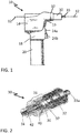
FIG. 1 depicts a cannulated surgical drill according to an embodiment. -
FIG. 2 depicts a perspective view of a cannulated hammer drill attachment according to an embodiment. -
FIG. 3 depicts an exploded perspective view of the cannulated hammer drill attachment ofFIG. 2 according to an embodiment. -
FIG. 4 illustrates the engagement between transmission plates of a cannulated hammer drill according to an embodiment. -
FIG. 5 depicts a Kirschner wire having a bent tip for producing curved holes in bone according to an embodiment. -
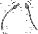
FIG. 6A depicts an exemplary device for fixing a bone according to an embodiment. -
FIG. 6B depicts interior portions of the exemplary device ofFIG. 6A according to an embodiment. - The pelvic bones exhibit many areas of curvature. Fractures of the pelvic bones therefore may often require curved intramedullary anchors to fix the bones. However, to use curved anchors, the holes for receipt of the anchors must also be curved and typical drill arrangements do not allow for the formation of curved holes. Curved holes may be created by using a bent and sharpened tip on the end of a piece of flexible wire, and advancing the wire into the bone by a hammering action. The hammering action may be provided by a cannulated hammer drill system as described with reference to
FIGS. 1-3 , and the wire may have a configuration as depicted inFIG. 5 . - Flexible drill wires, such as the
wire 50 depicted inFIG. 5 , which may be used to produce curved holes, may be formed from materials such as nitinol (nickel titanium) or spring tempered stainless steel, for example. Depending on the diameter desired for the hole, thewire 50 may have a diameter from about 0.5 mm to about 5 mm. In embodiments, thewire 50 may have a diameter of about 0.5 mm, about 0.75 mm, about 1.0 mm, about 1.25 mm, about 1.5 mm, about 1.75 mm, about 2.0 mm, about 2.5 mm, about 3.0 mm, about 3.5 mm, about 4.0 mm, about 5.0 mm, or any diameter between any two of the listed values. To enable thewire 50 to be advanced in a non-linear direction with respect to the longitudinal axis of the wire, thetip 52 of the wire may be bent at an angle from the longitudinal axis. Theangled tip 52 may have a length of about 5 mm to about 12 mm extending from the end. In embodiments, theangled tip 52 may have a length of about 5 mm, about 6 mm, about 7 mm, about 8 mm, about 9 mm, about 10 mm, about 11 mm, about 12 mm, or any length between any of the listed values. Theangled tip 52 may be bent from the longitudinal axis at an angle A of about 25º to about 35º. In embodiments, theangled tip 52 may be disposed at an angle A of about 25º, about 26º, about 27º, about 28º, about 29º, about 30º, about 31º, about 32º, about 33º, about 34º, about 35º, or any angle between any of the listed values. As an example, adrill wire 50 may be on the order of about 1.5 mm in diameter, and may include abent tip 52 of about 10 mm in length at an angle A of about 30°. - A
drill wire 50 may be advanced within the soft cancellous bone inside the pelvis by means of a hammering action. Thebent tip 52 will cause thewire 50 to turn, or be directed off axis in the direction of the angled tip as the wire is advanced. If thewire 50 is able to be rotated to turn thetip 52 in any arbitrary orientation, the overall direction of the wire can be made to bend in the direction which is required. Straight paths may be approximated by alternately turning thetip 52 at 180º offsets and producing several short curved paths in opposing directions. A fluoroscope may be used to continuously monitor the position of the drill in the bone, and allow adjustments to be made as the hole is being formed. The process of producing curved holes within the pelvis is aided by the outer structure of hard cortical bone which can partially guide the wire within the softer cancellous bone of the pelvis. - To produce the hammering action needed to drive the
wire drill 50 into bone, ahammer drill attachment 30 may be attached to a standard bi-directionalsurgical drill 10 as shown inFIG. 1 . - With reference to
FIG. 1 , there is illustrated asurgical drill 10 which may be a cannulated drill configured for accepting a Kirschner wire 12 (also referred to as a "K-wire" or "K-pin") through the cannula thereof. Thedrill 10 may be a bi-directional drill, while use of a unidirectional drill may also be contemplated. Some examples of surgical drills are the MPower® and PowerPro® devices manufactured by ConMed Linvatec of Largo Florida. - With the inclusion of a cannulated hammer-
drill attachment 30, discussed in more detail with reference toFIGS. 2 and3 , asurgical drill 10 may be adapted to drive theKirschner pin 12 into the bone. If thepins 12 are configured as discussed with reference to wire 50 ofFIG. 5 , curved hole paths may be formed in the bone. Hammer-drill attachment 30 may be attached to the drill body by means of anattachment device 32. Thedrill 10 may also be used with other types of attachments, and some examples of additional attachments which may be used include, but are not limited to, keyless chucks, quick-connect drill attachments, reamers, sagittal saws, and reciprocating saws. - While a cannulated drill may have a variety of configurations, in general, a
drill 10 may include amotor housing 14, agear housing 16 forwardly thereof, a depending pistol-grip handle 18, and aremovable battery pack 20 which may form a part of the pistol-grip handle. Thehandle 18 may be ergonomically designed and include a pair oftriggers trigger 24a may provide a first, or forward direction of rotation, andtrigger 24b may provide a second, or reverse direction of rotation. Thetriggers drill attachment 30 may include a rotary connection member, such as acollet 33, for engaging the K-wire 12 and rotating the K-wire with the rotation of the drill motor. During usage of such a configuration, a surgeon may control the operation of the drill (speed, direction of rotation, insertion or withdrawal) with one hand. - As depicted in
FIG. 1 , surgical drills, including cannulated surgical drills, may have two separate buttons to control direction, unlike conventional drills which generally have one trigger to run the drill and a separate bi-stable switch to control direction. Thehammer drill attachment 30 ofFIGS. 2 and3 includes a clutch 32, which may be a unidirectional bearing, and which exploits the bi-directional design. Thisclutch bearing 32 allows the attachment to provide free rotation in a first direction of rotation, while inhibiting rotation in the opposite, second direction and allowing the rotation in the second direction to be converted into a hammering motion. Theattachment 30 may have ahousing 40 that retains the attachment parts and provides anattachment portion 42 to engage with and fixedly retain the housing on the drill to prohibit rotation of the housing upon operation of the drill. -
Attachment 30 includes aninput shaft 34 configured to receive rotary motion from an output member (not shown) of a rotary drill in each of the first direction of rotation and the second direction of rotation of the drill.Input shaft 34 rotates freely in both directions.Attachment 30 also includes anoutput shaft 35 configured for outputting rotary motion or pulsed axial percussions, and atransmission arrangement 31 connecting the input shaft with the output shaft. In an embodiment as depicted inFIGS. 2 and3 , theinput shaft 34 andoutput shaft 35 are in axial alignment and are cannulated for receipt of a K-wire therethrough, and may therefore be used with cannulated surgical drills. - The
transmission arrangement 31 is configured to transmit rotary motion from theinput shaft 34 to theoutput shaft 35 during rotation of the input shaft in the first direction of rotation, and is also configured to convert rotary motion of the input shaft to pulsed axial percussions of the output shaft during rotation of the input shaft in the second direction of rotation. In an embodiment, thetransmission arrangement 31 may include afirst transmission member 36 disposed in conjunction with theinput shaft 34 to receive corresponding rotary motion from the input shaft during rotation of the input shaft in each of the first direction of rotation and the second direction of rotation. Thetransmission arrangement 31 may also include asecond transmission member 37 disposed in conjunction with thefirst transmission member 36 and theoutput shaft 35 to transfer the rotary motion of the first transmission member to the output shaft during rotation of the input shaft in the first direction of rotation, and convert the rotary motion of the first transmission member to pulsed axial percussions and transfer the pulsed axial percussions to the output shaft during rotation of the input shaft in the second direction of rotation. - The
input shaft 34 has a first end configured to be connected to an output member of a drill and a second end spaced apart from the first end and disposed within thehousing 40. Theoutput shaft 35 has a first end disposed within thehousing 40 adjacent the second end of the input shaft and a second end spaced apart from the first end. Thefirst transmission member 36 may be fixedly attached on the second end of theinput shaft 34 for rotation of the first transmission member with the input shaft, and thesecond transmission member 37 may be fixedly attached on the first end of theoutput shaft 35 for movement of the output shaft with the second transmission member. In the embodiment as depicted inFIGS. 2 and3 , the first transmission member is configured as a saw-tooth disc 36, and the second transmission member is configured as a saw-tooth disc 37. - In an embodiment, at least one of the first transmission member and the second transmission member (corresponding with either 36 or 37 in the embodiment of
FIG. 3 ) may be a disc-shaped member having a surface disposed towards the other of the first transmission member and the second transmission member. As shown inFIG. 3 , the surface of the disc shapedmember FIG. 4 , the teeth may have a right-triangular cross-section in the annular direction with a face portion disposed at an angle to the surface and a leg portion disposed axially to the surface. - In an embodiment, the other of the first transmission member and the second transmission member (corresponding with the other of either 36 or 37 in the embodiment of
FIG. 3 ) may be configured as an engagement device having at least one projection that is configured to engage with the leg portions of the teeth during rotation of theinput shaft 34 in the first direction of rotation to rotate the second transmission member with the first transmission member, and glidingly move over the face portions of the teeth during rotation of the input shaft in the second direction of rotation to axially displace theoutput shaft 35 by an amount which is substantially the height of the teeth from the surface of the disc (see h inFIG. 4 ). A biasing member, which may be configured as a wave washer, such aswave washer 38 inFIG. 3 , may be disposed to provide biased engagement between the teeth of the one transmission member and the at least one projection of the other transmission member. - In the embodiment as depicted in
FIGS. 2 and3 , both of the first andsecond transmission members FIG. 4 , the teeth on thedisc members disc member 36 in a first direction of rotation as represented by panel A ofFIG. 4 , the leg portions of the teeth of thefirst disc member 36 engage with the leg portions of the teeth of thesecond disc member 37 and rotate the second disc member with the first disc member. However, as represented by panels B-D ofFIG. 4 , upon rotation of thefirst disc member 36 in the opposite direction, sincedisc member 37 is prevented from rotating in the opposite direction by theuni-directional bearing 32, the teeth of the first disc member slide over the face portions of the teeth of the second disc member to axially displace the second disc member by an amount h corresponding to the height of the teeth. After the teeth pass over one another, the discs snap back together (panel D) and an axial hammering movement is created. - This axial displacement results in an axial displacement of the
output shaft 35, and any surgical implement connected with the output shaft via thecollet 33. In some designations, the term 'chuck' may be used interchangeably with the term 'collet.' Acollet 33 may include an engagingmember 33b through which the article to be retained is held, and an internally threadedcap 33a that may be threadable onto the end of theshaft 35 to compress the engaging member around the implement to be retained. - A
unidirectional bearing 32 prohibits rotation of thesecond disc member 37 andshaft 35 in the second direction. Abushing 44 may be provided to allow for axial movement of theshaft 35 within theunidirectional bearing 32.Additional bearings shafts rings 48 may be used to hold the various components in place within the housing and on the shafts. A spacer ring 49 may also be included to provide a bearing surface for thewave washer 38. - A
hammer drill attachment 30 may be packaged and sold individually as an accessory for rotary drills, or alternatively may be included in a pre-packaged kit. A kit may include a drill, such asdrill 10 ofFIG. 1 , as well as assorted attachment devices, such as thehammer drill attachment 30 or any of the previously mentioned attachments including keyless chucks, quick-connect drill attachments, reamers, sagittal saws, and reciprocating saws. - A
hammer drill attachment 30 as shown inFIG. 2 and constructed as shown in the exploded view ofFIG. 3 has ahousing 40 that has anattachment portion 42 which is configured to be attached to a drill, such asdrill 10 ofFIG. 1 . Theattachment portion 42 may be configured as needed to enable theattachment 30 to be used for various models ofdrills 10. Theattachment 30 has aninput shaft 34 that engages with the drive of the drill and anoutput shaft 35 coaxial with the input shaft. Acollet 33 is provided on theoutput shaft 35 to connect the output shaft with a drill wire. The shafts are cannulated for passage of a surgical drill wire therethrough to enable the attachment to be used with cannulated surgical drills. Theattachment 30 is configured with a transmission arrangement that allows theoutput shaft 35 to rotate only in one direction upon rotation of theinput shaft 34 in a first direction. Upon rotation of theinput shaft 34 in the opposite direction, the transmission converts the rotation into a hammering action to produce a hammering action at theoutput shaft 35. - A surgical drill kit may include a cannulated surgical drill such as
drill 10 ofFIG. 1 . A cannulatedhammer drill attachment 30 may be included as part of the kit, and various other optional attachment devices may also be included, such as keyless chucks, quick-connect drill attachments, reamers, sagittal saws, and reciprocating saws. In addition to any attachment devices, device accessories may also be included such as rechargeable batteries, saw blades, and drill bits, and may include drill wires, such as various gauges ofKirschner wires 12 ofFIG. 1 and/or adrill wire 50 ofFIG. 5 . Kits may be sold as pre-packaged assortments of contents, or may be custom ordered to create a kit that meets the needs of a particular surgeon. - An incision of approximately 3 cm will be made in a patient at a location from which the surgeon wishes to approach the broken bone. Upon exposing the bone, the surgeon will drill a first hole through the outer cortical bone using a surgical drill (such as
drill 10 ofFIG. 1 ) equipped with a standard drill chuck and an appropriate drill bit. The hole will be drilled using the forward drill rotation button to drill into the bone. The standard drill chuck will be removed and a cannulatedhammer drill attachment 30 will be affixed to the drill via theattachment portion 42 of thehousing 40. A K-wire (50 ofFIG. 5 ) having a diameter of about 1.5 mm and a sharpened tip of about 10 mm disposed at an angle A of about 30° from the axis of the wire will then be inserted through the cannula of the drill and hammer drill attachment. - A fluoroscope will be used to track progress of the wire through the bone. The bent and sharpened tip will be inserted into the drilled hole and directed in a first direction in which it is desired to form a curved hole. The surgeon will press the reverse rotation button and produce a hammering output to drive the tip and wire into the cancellous bone to divert the hole in the first direction. Upon reaching a satisfactory extent of curvature of the hole in the desired first direction and wishing to then proceed in a straight path, the surgeon will rotate the tip 180º from the first direction and hammer drive the wire into the bone approximately another 0.5 cm to 1 cm. The tip will again be rotated 180º back to its original direction and advance by hammering another approximately 0.5 cm to 1 cm. This back and forth reversal of direction will be repeated until an approximately straight hole of a desired length is achieved. Further curvature, and/or straight path segments will be made as needed in the manner as discussed above to produce a bore within the bone in a desired position for receipt of a fixation anchor therein.
- The K-wire will be left in place, and the curved bore established by the K-wire will be enlarged to about 10 mm diameter by placing a cannulated reamer having a flexible cannulated drive shaft on the K-wire. With visualization provided by the fluoroscope, the reamer will be advanced along the K-wire to approximately the bent tip of the wire. The reamer and wire will be withdrawn leaving an open 10 mm diameter bore through the bone. A fixation device, such as the
device 200 as illustrated inFIGS. 6A and 6B , having a corresponding diameter will be inserted into the bore. Thedevice 200 may include aflexible tube 205, a stiffening mechanism 210, anactuator 215, and a threadedscrew anchor portion 235. - The
anchor portion 235 will be threaded into the bone at the end of the bore to anchor thedevice 200 in place. Theflexible tube 205 may have adistal end 205a and aproximal end 205b. Theflexible tube 205 may include a plurality of slits, such as 206, in an outer housing configured to allow the flexible tube to flex. In an embodiment, theflexible tube 205 may comprise stainless steel and/or nitinol. The stiffening mechanism 210 may be located within theflexible tube 205 and may be configured to cause the flexible tube to become rigid. In an embodiment, the stiffening mechanism 210 may include a plurality ofexpansion sleeves 240 abutting one another at joints 225. Thesleeves 240 will be actuated by rotation of theactuator 215 to expand the sleeves to abut an interior surface of theflexible tube 205 thereby causing the tube to become rigid. A lockingassembly 230 will then be engaged with thecap 220 to retain the system in a rigid locked configuration to hold the bone fragments in place. - This disclosure is not limited to the particular devices described, as these may vary. The terminology used in the description is for the purpose of describing the particular versions or embodiments only, and is not intended to limit the scope.
- In the above detailed description, reference is made to the accompanying drawings, which form a part hereof. In the drawings, similar symbols typically identify similar components, unless context dictates otherwise. The illustrative embodiments described in the detailed description and drawings are not meant to be limiting. Other embodiments may be used, and other changes may be made, without departing from the scope of the subject matter presented herein. It will be readily understood that the aspects of the present disclosure, as generally described herein, and illustrated in the Figures, can be arranged, substituted, combined, separated, and designed in a wide variety of different configurations, all of which are explicitly contemplated herein.
- The present disclosure is not to be limited in terms of the particular embodiments described in this application, which are intended as illustrations of various aspects. Many modifications and variations can be made without departing from its scope, as will be apparent to those skilled in the art. Functionally equivalent methods and apparatuses within the scope of the disclosure, in addition to those enumerated herein, will be apparent to those skilled in the art from the foregoing descriptions. The present disclosure is to be limited only by the terms of the appended claims.
- It is also to be understood that the terminology used herein is for the purpose of describing particular embodiments only, and is not intended to be limiting.
- Unless defined otherwise, all technical and scientific terms used herein have the same meanings as commonly understood by one of ordinary skill in the art. As used in this document, the term "comprising" means "including, but not limited to."
- While various devices are described in terms of "comprising" various components (interpreted as meaning "including, but not limited to"), devices can also "consist essentially of" or "consist of" the various components and such terminology should be interpreted as defining essentially closed-member groups.
- It will be understood by those within the art that, in general, terms used herein, and especially in the appended claims are generally intended as "open" terms (e.g., the term "including" should be interpreted as "including but not limited to," the term "having" should be interpreted as "having at least," the term "includes" should be interpreted as "includes but is not limited to," etc.). It will be further understood by those within the art that if a specific number of an introduced claim recitation is intended, such an intent will be explicitly recited in the claim, and in the absence of such recitation no such intent is present. For example, as an aid to understanding, the following appended claims may contain usage of the introductory phrases "at least one" and "one or more" to introduce claim recitations. However, the use of such phrases should not be construed to imply that the introduction of a claim recitation by the indefinite articles "a" or "an" limits any particular claim containing such introduced claim recitation to embodiments containing only one such recitation, even when the same claim includes the introductory phrases "one or more" or "at least one.
Claims (16)
- A hammer drill attachment (30) for a rotary drill, the rotary drill comprising an axially cannulated output member rotatable in a first direction and in a second direction opposite the first direction, wherein the hammer drill attachment (30) comprises:an input shaft (34) configured to receive rotary motion from the output member of the rotary drill;an output shaft (35) configured to output rotary motion or pulsed axial percussions; anda transmission (31) connecting the input shaft (34) with the output shaft (35) and configured to transmit rotary motion from the input shaft (34) to the output shaft (35) during rotation of the input shaft (34) in the first direction of rotation and to convert rotary motion of the input shaft (34) to pulsed axial percussions of the output shaft (35) during rotation of the input shaft (34) in the second direction of rotation;wherein the input shaft (34) and output shaft (35) are axially aligned and are configured to be axially aligned with the output member of the rotary drill;characterized in that the input shaft (34) and output shaft (35) comprise an axial cannulation extending therethrough and configured to receive at least one elongated surgical implement (12; 50) therethrough, and
the output shaft (35) comprises a device (33; 33a; 33b) configured to fixedly connect the output shaft (35) with the at least one surgical implement (12; 50) to rotate or axially pulse the at least one surgical implement (12; 50) with the output shaft (35). - The hammer drill attachment (30) of claim 1, further comprising a device (32) to prohibit rotary motion of the output shaft (35) in the second direction of rotation during rotation of the input shaft (34) in the second direction of rotation.
- The hammer drill attachment (30) of claim 1, wherein the transmission (31) comprises:a first transmission member (36) disposed in conjunction with the input shaft (34) to receive corresponding rotary motion from the input shaft (34) during rotation of the input shaft (34) in each of the first direction of rotation and the second direction of rotation; anda second transmission member (37) disposed in conjunction with the first transmission member (36) and the output shaft (35), the second transmission member (37) being configured to:during rotation of the input shaft (34) in the first direction of rotation, transfer the rotary motion of the first transmission member (36) to the output shaft (35), andduring rotation of the input shaft (34) in the second direction of rotation, convert the rotary motion of the first transmission member (36) to pulsed axial percussions and transfer the pulsed axial percussions to the output shaft (35).
- The hammer drill attachment (30) of claim 3, wherein:the input shaft (34) has a first end configured to be connected to the output member of the rotary drill and a second end spaced apart from the first end;the output shaft (35) is in axial alignment with the input shaft (34) and has a first end disposed adjacent the second end of the input shaft (34) and a second end spaced apart from the first end;the first transmission member (36) is fixedly attached on the second end of the input shaft (34) to rotate the first transmission member (36) with the input shaft (34); andthe second transmission member (37) is fixedly attached on the first end of the output shaft (35) to move the output shaft (35) with the second transmission member (37).
- The hammer drill attachment (30) of claim 3, wherein:at least one of the first transmission member (36) and the second transmission member (37) comprises a disc-shaped member having a surface disposed towards the other of the first transmission member (36) and the second transmission member (37), the surface comprising a plurality of teeth disposed annularly about an axis defined by the input shaft (34) and the output shaft (35), wherein the teeth have a right-triangular cross-section in the annular direction with a face portion disposed at an angle to the surface and a leg portion disposed axially to the surface;the other of the first transmission member (36) and the second transmission member (37) comprises at least one projection configured to:engage with the leg portions of the teeth during rotation of the input shaft (34) in the first direction of rotation to rotate the second transmission member (37) with the first transmission member (36), andglidingly move over the face portions of the teeth during rotation of the input shaft (34) in the second direction of rotation to axially displace the output shaft (35); andthe attachment further comprises a biasing member (38) to provide biased engagement between the teeth and the at least one projection.
- The hammer drill attachment (30) of claim 4, wherein:the first transmission member (36) comprises a first disc-shaped member (36) disposed on the second end of the input shaft (34), the first disc-shaped member (36) comprising:a surface disposed towards the first end of the output shaft (35) and having a peripheral edge, anda plurality of teeth disposed on the surface adjacent at least the peripheral edge, wherein the teeth have a right-triangular cross-section in the peripheral direction with a face portion disposed at an angle to the surface and a leg portion disposed axially to the surface;the second transmission member (37) comprises a second disc-shaped member (37) disposed on the first end of the output shaft (35), the second disc-shaped member (37) comprising:a surface disposed towards the surface of the first transmission member (36) and having a peripheral edge, anda plurality of teeth disposed on the surface adjacent at least the peripheral edge, wherein the teeth have a right-triangular cross-section in the peripheral direction with a face portion disposed at an angle to the surface and a leg portion disposed axially to the surface; andthe teeth on the surface of the first disc-shaped member (36) are complementary to the teeth on the surface of the second disc-shaped member (37), wherein:the leg portions of the teeth of the first disc-shaped member (36) engage with the leg portions of the teeth of the second disc-shaped member (37) during rotation of the input shaft (34) in the first direction of rotation to rotate the second transmission member (37) with the first transmission member (36), andthe face portions of the teeth of the first disc-shaped member (36) slide over the face portions of the teeth of the second disc-shaped member (37) during rotation of the input shaft (34) in the second direction of rotation to axially displace the second transmission member (37) with respect to the first transmission member (36) to axially displace the output shaft (35).
- The hammer drill attachment (30) of claim 6, further comprising a biasing member (38) to provide biased engagement between the teeth on the surface of the first disc-shaped member (36) and the teeth on the surface of the second disc-shaped member (37).
- The hammer drill attachment (30) of claim 5 or 6, further comprising a device (32) to prohibit rotary motion of the output shaft (35) during rotation of the input shaft (34) in the second direction of rotation.
- The hammer drill attachment (30) of claim 6, further comprising a housing (40), wherein:the input shaft (34) and first transmission member (36) are axially fixed within the housing (40);the output shaft (35) and second transmission member (37) are axially displaceable within the housing (40); andthe housing (40) comprises a portion to engage with a body portion (42) of the rotary drill to prohibit rotation of the attachment with respect to the drill.
- The hammer drill attachment (30) of claim 6, further comprising:a housing (40);at least one first bearing (46) disposed around the input shaft (34) between the input shaft (34) and the housing (40); andat least one second bearing (32) disposed around the output shaft (35) between the output shaft (35) and the housing (40), and configured to permit rotation of the output shaft (35) in the first direction and prohibit rotation of the output shaft (35) in the second direction of rotation.
- The hammer drill attachment (30) of claim 10, wherein the second bearing (32) is fixedly positioned within the housing (40), and the attachment further comprises a wave washer (38) disposed between the second bearing (32) and the second disc-shaped member (37) to bias the second disc-shaped member (37) in a direction away from the second bearing (32) and into engagement with the first disc-shaped member (36).
- The hammer drill attachment (30) of claim 10, wherein the housing (40) comprises a portion to engage with a body portion (42) of the rotary drill to prohibit rotation of the attachment with respect to the drill.
- The hammer drill attachment (30) of claim 1, wherein the attachment is configured for use with a cannulated surgical drill.
- The hammer drill attachment (30) of claim 1, wherein the cannulation is configured to receive at least one of a drill wire (50) and a surgical pin (12) therethrough.
- The hammer drill attachment (30) of claim 1, wherein the output shaft (35) comprises a retaining element or a collet (33) to axially and rotationally retain a surgical implement (12; 50) therein.
- A surgical drill kit comprising:
a rotary cannulated drill having an output member rotatable in a first direction and in a second direction opposite the first direction, the output member having an axial bore therein; and the hammer drill attachment (30) according to one of the above claims, further configured to be fixedly attached to the drill, the attachment further comprising a housing (40) comprising an attachment portion to non-rotationally connect the housing (40) to the drill.
Applications Claiming Priority (1)
| Application Number | Priority Date | Filing Date | Title |
|---|---|---|---|
| PCT/CA2012/050807 WO2014075165A1 (en) | 2012-11-14 | 2012-11-14 | Cannulated hammer drill attachment |
Publications (3)
| Publication Number | Publication Date |
|---|---|
| EP2919689A1 EP2919689A1 (en) | 2015-09-23 |
| EP2919689A4 EP2919689A4 (en) | 2016-11-23 |
| EP2919689B1 true EP2919689B1 (en) | 2018-06-13 |
Family
ID=50730423
Family Applications (2)
| Application Number | Title | Priority Date | Filing Date |
|---|---|---|---|
| EP12888609.0A Not-in-force EP2919689B1 (en) | 2012-11-14 | 2012-11-14 | Cannulated hammer drill attachment |
| EP13854268.3A Withdrawn EP2919690A4 (en) | 2012-11-14 | 2013-11-14 | FOREST ACCESSORY FOR TUBULAR SURGICAL DRILLS |
Family Applications After (1)
| Application Number | Title | Priority Date | Filing Date |
|---|---|---|---|
| EP13854268.3A Withdrawn EP2919690A4 (en) | 2012-11-14 | 2013-11-14 | FOREST ACCESSORY FOR TUBULAR SURGICAL DRILLS |
Country Status (4)
| Country | Link |
|---|---|
| US (4) | US9532789B2 (en) |
| EP (2) | EP2919689B1 (en) |
| CN (2) | CN104837427B (en) |
| WO (2) | WO2014075165A1 (en) |
Cited By (1)
| Publication number | Priority date | Publication date | Assignee | Title |
|---|---|---|---|---|
| CN112296390A (en) * | 2020-11-09 | 2021-02-02 | 武义县亚太电器有限公司 | Electric drill structure convenient for drilling inclined hole |
Families Citing this family (32)
| Publication number | Priority date | Publication date | Assignee | Title |
|---|---|---|---|---|
| US8926529B2 (en) | 2009-02-10 | 2015-01-06 | Vesatek, Llc | Method and apparatus for manipulating a surgical guidewire |
| US9839435B2 (en) | 2011-11-14 | 2017-12-12 | The University Of British Columbia | Intramedullary fixation system for management of pelvic and acetabular fractures |
| EP2919689B1 (en) * | 2012-11-14 | 2018-06-13 | British Columbia Cancer Agency Branch | Cannulated hammer drill attachment |
| WO2015134750A1 (en) | 2014-03-06 | 2015-09-11 | University Of British Columbia | Shape adaptable intramedullary fixation device |
| EP4245233A3 (en) | 2014-10-14 | 2023-12-06 | The University of British Columbia | Systems for intramedullary bone fixation |
| DE102015206634A1 (en) * | 2015-04-14 | 2016-10-20 | Robert Bosch Gmbh | Tool attachment for a hand tool |
| EP3334489B1 (en) * | 2015-08-12 | 2021-05-19 | Vesatek, Llc | System for manipulating an elongate medical device |
| FR3046724B1 (en) * | 2016-01-18 | 2021-03-05 | Clariance | CANNULATED FLEXIBLE Burr |
| AU2017323632B2 (en) | 2016-09-08 | 2021-11-04 | Meduloc, Llc | Implant and method for long bone fixation |
| EP3568083B1 (en) | 2017-03-07 | 2021-04-28 | Piper Access, LLC. | Safety shields for elongated instruments and related systems |
| WO2019094834A1 (en) * | 2017-11-09 | 2019-05-16 | Inceptus Medical LLC | Interlocking loop coupling/decoupling system for deploying vascular implant devices |
| CN107971525B (en) * | 2017-12-06 | 2024-08-27 | 浙江龙游诚创五金有限公司 | Soft multi-angle drilling device |
| US11304709B2 (en) | 2018-01-25 | 2022-04-19 | Medtronic Holdings Company Sarl | Adaptor and drill for use with a driver and a cannula for drilling into bone |
| US10980587B2 (en) | 2018-01-25 | 2021-04-20 | Medtronic Holding Company Sàrl | Adaptor for use with a driver, a drill, and a cannula for drilling into bone |
| ES2953372T3 (en) * | 2018-02-20 | 2023-11-10 | Piper Access Llc | Drilling devices and related methods |
| US11832856B2 (en) | 2018-10-17 | 2023-12-05 | The University Of British Columbia | Bone-fixation device and system |
| EP3866712A1 (en) | 2018-10-17 | 2021-08-25 | Curvafix, Inc. | Intramedullary fixation device |
| RU198419U1 (en) * | 2019-06-10 | 2020-07-06 | Открытое акционерное общество "Медикоинструментальный завод имени В.И. Ленина" | MINIDREL MANUAL UNIVERSAL |
| CN120531451A (en) | 2019-09-27 | 2025-08-26 | 巴德阿克塞斯系统股份有限公司 | Self-advancement feature of intraosseous devices |
| EP4034008B1 (en) | 2019-09-27 | 2025-06-04 | Bard Access Systems, Inc. | Constant-torque intraosseous access devices |
| CN113520512B (en) | 2020-04-21 | 2026-01-02 | 巴德阿克塞斯系统股份有限公司 | Reusable push-activated intraosseous access device |
| US11998237B2 (en) | 2020-06-03 | 2024-06-04 | Bard Access Systems, Inc. | Intraosseous device including a sensing obturator |
| CN111938745B (en) * | 2020-08-20 | 2021-06-01 | 北京华腾创新科技有限公司 | Medical universal drill |
| CN114098918B (en) | 2020-08-25 | 2025-12-12 | 巴德阿克塞斯系统股份有限公司 | Angled intraosseous access system |
| EP4203821B1 (en) | 2020-09-01 | 2025-10-29 | Bard Access Systems, Inc. | Retractable intraosseous access system |
| CN215839325U (en) | 2020-09-09 | 2022-02-18 | 巴德阿克塞斯系统股份有限公司 | Suction device for an intraosseous access system |
| USD1042073S1 (en) * | 2020-09-10 | 2024-09-17 | Robert Bosch Gmbh | Power tool accessory |
| CN114903553A (en) | 2021-02-08 | 2022-08-16 | 巴德阿克塞斯系统股份有限公司 | Intraosseous access system and method for drilling through bone |
| US20250009362A1 (en) * | 2021-11-18 | 2025-01-09 | Phasor Health, Llc | Quick-connect k-wire module |
| CN116236265B (en) * | 2021-12-07 | 2025-10-31 | 苏州微创脊柱创伤医疗科技有限公司 | Fixing clamp |
| US12588930B2 (en) | 2022-02-04 | 2026-03-31 | Curvafix, Inc. | Devices, systems, and methods of use for delivery of materials in combination with intramedullary devices |
| WO2024035819A1 (en) * | 2022-08-09 | 2024-02-15 | Stryker Corporation | Surgical handpiece for driving orthopedic pins and related accessories |
Family Cites Families (68)
| Publication number | Priority date | Publication date | Assignee | Title |
|---|---|---|---|---|
| US2328270A (en) * | 1942-06-01 | 1943-08-31 | Greenberg Harry Daniel | Oscillatory hammer |
| US2724573A (en) | 1954-07-26 | 1955-11-22 | Axel E Lundquist | Percussion attachment for portable drills |
| US3006202A (en) * | 1958-03-17 | 1961-10-31 | Samuel J Forbes | Rotary and percussive tool |
| NL147356B (en) * | 1965-03-05 | 1975-10-15 | Tech Metaalproducten Huygmetaa | HAMMER STARTING HOUSING FOR A DRILL ENGINE HOUSING. |
| US3650336A (en) * | 1970-05-05 | 1972-03-21 | Rockwell Mfg Co | Power driven device |
| DE2136523C3 (en) * | 1971-07-21 | 1983-11-03 | Hilti AG, 9494 Schaan | Electric hammer |
| FR2258585B1 (en) | 1974-01-17 | 1977-06-10 | Legris France Sa | |
| IT1066884B (en) | 1976-08-09 | 1985-03-12 | Star Utensili Elett | DRILL OF THE PERCUSSION TYPE |
| DE2832169A1 (en) * | 1978-07-21 | 1980-01-31 | Hilti Ag | MOTORIZED DRILLING HAMMER |
| US4489792A (en) * | 1981-05-28 | 1984-12-25 | Fahim Atef E F | Hammer drill adapter |
| US4441563A (en) | 1981-11-02 | 1984-04-10 | Black & Decker Inc. | Tool collet and control means |
| US4491443A (en) * | 1982-10-29 | 1985-01-01 | Textron Inc. | Modified quick release adapter |
| US4605348A (en) * | 1982-10-29 | 1986-08-12 | Textron Inc. | Quick release adapter |
| US4468826A (en) * | 1982-06-11 | 1984-09-04 | Black & Decker Inc. | Hammer-drill for masonry fasteners |
| US4450919A (en) * | 1983-01-03 | 1984-05-29 | Cousineau Bernard L | Drill attachment |
| DE3504650C2 (en) * | 1985-02-12 | 1994-01-20 | Bosch Gmbh Robert | Hammer drill with increased actuation force for the coupling of the impact drive |
| US5015247A (en) * | 1988-06-13 | 1991-05-14 | Michelson Gary K | Threaded spinal implant |
| US4998589A (en) * | 1990-02-26 | 1991-03-12 | Wiesendanger John A | Variable speed drill control cam apparatus |
| DE4010239A1 (en) * | 1990-03-30 | 1991-10-02 | Bosch Gmbh Robert | Hammer drill with rapid chuck changing mechanism - has torque transmitted by balls which can be extracted radially by turning outside locking ring |
| WO1993025151A1 (en) * | 1992-06-12 | 1993-12-23 | Larry Steven Nichter | Wire driver and method |
| US5476467A (en) * | 1994-06-14 | 1995-12-19 | Benoist; Louis A. | Surgical hammer for driving K-wires |
| US5494115A (en) * | 1994-10-25 | 1996-02-27 | Hwong; Steven | Electric hammer drill |
| DE19510964A1 (en) * | 1995-03-24 | 1996-09-26 | Hilti Ag | Hand tool for dry machining of brittle and / or ductile components and adapter for a hammer drill |
| EP0733443B1 (en) * | 1995-03-24 | 1997-10-29 | HILTI Aktiengesellschaft | Apparatus for transmitting percussive blows to a continuously rotating tool |
| JP3423497B2 (en) * | 1995-09-06 | 2003-07-07 | 株式会社マキタ | Bit mounting device for portable tools |
| DE19534850A1 (en) * | 1995-09-20 | 1997-03-27 | Hilti Ag | Impact-supported hand drill |
| GB9524180D0 (en) * | 1995-11-27 | 1996-01-31 | Black & Decker Inc | Hammer mechanism |
| JP3582760B2 (en) * | 1997-04-18 | 2004-10-27 | 日立工機株式会社 | Hammer drill |
| WO1998049944A1 (en) * | 1997-05-02 | 1998-11-12 | Pilling Weck Incorporated | Adjustable supporting bracket having plural ball and socket joints |
| GB9718312D0 (en) * | 1997-08-30 | 1997-11-05 | Black & Decker Inc | Power tool |
| US5996454A (en) * | 1998-01-23 | 1999-12-07 | Brinks, Jr.; James Ronald | Zero run-out brake lathe adapter |
| DE19834503A1 (en) * | 1998-07-31 | 2000-02-03 | Hilti Ag | Tool holder for drilling and chiseling tools |
| US5993454A (en) * | 1998-09-29 | 1999-11-30 | Stryker Corporation | Drill attachment for a surgical drill |
| US6209886B1 (en) * | 1999-04-30 | 2001-04-03 | Medtronic, Inc. | Resecting tool with independent variable axial extension for tool implements and guide sleeves |
| DE10034359A1 (en) * | 2000-07-14 | 2002-01-24 | Hilti Ag | Hitting electric hand tool device |
| CA2423295C (en) * | 2000-09-22 | 2009-05-12 | Ingersoll-Rand Company | Quick release drill bit for down-hole drills |
| JP4281273B2 (en) * | 2000-10-20 | 2009-06-17 | 日立工機株式会社 | Hammer drill |
| JP2002239835A (en) * | 2001-02-16 | 2002-08-28 | Makita Corp | Reciprocating tool |
| DE10205030A1 (en) * | 2002-02-07 | 2003-08-21 | Hilti Ag | Operating mode switching unit of a hand machine tool |
| US6780189B2 (en) | 2002-06-07 | 2004-08-24 | Medtronic, Inc. | Surgical instrument with a collet locking and indexing system |
| CA2390826C (en) * | 2002-06-17 | 2009-10-13 | Bob B. Ha | Hammer drill |
| US20050199407A1 (en) * | 2002-09-04 | 2005-09-15 | Aesculap Ag & Co. Kg | Surgical instrument |
| US7096972B2 (en) * | 2002-09-17 | 2006-08-29 | Orozco Jr Efrem | Hammer drill attachment |
| JP4270887B2 (en) * | 2003-01-10 | 2009-06-03 | 株式会社マキタ | Electric reciprocating tool |
| JP2005034913A (en) * | 2003-07-15 | 2005-02-10 | Hitachi Koki Co Ltd | Impact tool |
| US7237987B2 (en) * | 2003-08-08 | 2007-07-03 | Alltrade Tools Llc | Reversible drill and drive tool |
| CN2662839Y (en) * | 2003-12-10 | 2004-12-15 | 上海光电技术有限公司 | Medical hollow operation electric drill |
| JP4405900B2 (en) * | 2004-03-10 | 2010-01-27 | 株式会社マキタ | Impact driver |
| USD537940S1 (en) * | 2004-08-11 | 2007-03-06 | Synthes (Usa) | Head for surgical hammer |
| CN100358675C (en) * | 2004-10-14 | 2008-01-02 | 陈月辉 | Quick safety connecting mechanism |
| EP1690640B1 (en) * | 2005-02-10 | 2013-03-06 | Black & Decker Inc. | Hand-held hammer machine |
| US7314097B2 (en) * | 2005-02-24 | 2008-01-01 | Black & Decker Inc. | Hammer drill with a mode changeover mechanism |
| DE102005010265A1 (en) * | 2005-03-07 | 2006-09-14 | Robert Bosch Gmbh | Tool holder and hand tool |
| US20060237205A1 (en) * | 2005-04-21 | 2006-10-26 | Eastway Fair Company Limited | Mode selector mechanism for an impact driver |
| CN100420531C (en) * | 2005-05-26 | 2008-09-24 | 松下电工株式会社 | hammer drill |
| US7410007B2 (en) * | 2005-09-13 | 2008-08-12 | Eastway Fair Company Limited | Impact rotary tool with drill mode |
| JP5041575B2 (en) * | 2006-03-07 | 2012-10-03 | 日立工機株式会社 | Impact tool |
| US8460297B2 (en) * | 2007-01-05 | 2013-06-11 | Biomet 3I, Llc | Drill bit assembly for bone tissue including depth limiting feature |
| US20080181740A1 (en) * | 2007-01-29 | 2008-07-31 | Waitszies Roland G | Drill bit extension |
| CN101422823B (en) * | 2007-11-01 | 2012-07-18 | 苏州宝时得电动工具有限公司 | Power tool |
| US8926529B2 (en) * | 2009-02-10 | 2015-01-06 | Vesatek, Llc | Method and apparatus for manipulating a surgical guidewire |
| US8157021B2 (en) * | 2009-11-29 | 2012-04-17 | Chen Bo-Shen | Chisel adapter |
| CN102554300A (en) * | 2010-12-28 | 2012-07-11 | 苏州宝时得电动工具有限公司 | Chuck |
| US9839435B2 (en) * | 2011-11-14 | 2017-12-12 | The University Of British Columbia | Intramedullary fixation system for management of pelvic and acetabular fractures |
| DE102011089914A1 (en) * | 2011-12-27 | 2013-06-27 | Robert Bosch Gmbh | Hand tool device |
| DE102011089919A1 (en) * | 2011-12-27 | 2013-06-27 | Robert Bosch Gmbh | Hand tool device |
| DE102011089913A1 (en) * | 2011-12-27 | 2013-06-27 | Robert Bosch Gmbh | Hand tool device |
| EP2919689B1 (en) * | 2012-11-14 | 2018-06-13 | British Columbia Cancer Agency Branch | Cannulated hammer drill attachment |
-
2012
- 2012-11-14 EP EP12888609.0A patent/EP2919689B1/en not_active Not-in-force
- 2012-11-14 WO PCT/CA2012/050807 patent/WO2014075165A1/en not_active Ceased
- 2012-11-14 US US14/241,998 patent/US9532789B2/en active Active
- 2012-11-14 CN CN201280077563.XA patent/CN104837427B/en not_active Expired - Fee Related
-
2013
- 2013-11-14 EP EP13854268.3A patent/EP2919690A4/en not_active Withdrawn
- 2013-11-14 WO PCT/CA2013/050870 patent/WO2014075184A1/en not_active Ceased
- 2013-11-14 CN CN201380070362.1A patent/CN104918570B/en not_active Expired - Fee Related
- 2013-11-14 US US14/440,839 patent/US9615835B2/en active Active
-
2016
- 2016-10-26 US US15/335,218 patent/US20170049460A1/en not_active Abandoned
-
2017
- 2017-02-23 US US15/441,226 patent/US20170164953A1/en not_active Abandoned
Non-Patent Citations (1)
| Title |
|---|
| None * |
Cited By (1)
| Publication number | Priority date | Publication date | Assignee | Title |
|---|---|---|---|---|
| CN112296390A (en) * | 2020-11-09 | 2021-02-02 | 武义县亚太电器有限公司 | Electric drill structure convenient for drilling inclined hole |
Also Published As
| Publication number | Publication date |
|---|---|
| WO2014075165A1 (en) | 2014-05-22 |
| US9615835B2 (en) | 2017-04-11 |
| EP2919690A4 (en) | 2016-09-07 |
| US9532789B2 (en) | 2017-01-03 |
| US20150297245A1 (en) | 2015-10-22 |
| CN104837427A (en) | 2015-08-12 |
| EP2919689A1 (en) | 2015-09-23 |
| EP2919689A4 (en) | 2016-11-23 |
| EP2919690A1 (en) | 2015-09-23 |
| WO2014075184A1 (en) | 2014-05-22 |
| CN104837427B (en) | 2017-09-22 |
| CN104918570B (en) | 2017-07-28 |
| US20170164953A1 (en) | 2017-06-15 |
| CN104918570A (en) | 2015-09-16 |
| US20150038970A1 (en) | 2015-02-05 |
| US20170049460A1 (en) | 2017-02-23 |
Similar Documents
| Publication | Publication Date | Title |
|---|---|---|
| US9532789B2 (en) | Cannulated hammer drill attachment | |
| US11564699B2 (en) | Handheld surgical instrument | |
| US8845668B2 (en) | Arthroscopic shaver handpiece with modular attachments | |
| JP5883786B2 (en) | Surgical instrument for cutting a cavity in an intramedullary canal | |
| JP5921544B2 (en) | Protection sleeve retention mechanism | |
| US20090254094A1 (en) | Ratcheting mechanical driver for cannulated surgical systems | |
| US8535316B2 (en) | Hollow reamer for medical applications | |
| US20180103963A1 (en) | Medical device handpiece with interchangeable rotary head and drill bit | |
| US20100191195A1 (en) | Cannulated apparatus and method relating to microfracture and revascularization methodologies | |
| AU2017268657B2 (en) | Methods and devices for cutting and removing tissue from a body | |
| KR200487712Y1 (en) | Shaver For Surgery | |
| WO2015006876A1 (en) | Coupling device for medical instrument or medical power-tool chuck | |
| WO2008031245A2 (en) | Surgical drilling device | |
| JP6474906B2 (en) | Bone drilling reamer | |
| US20070118050A1 (en) | Bone graft harvest device | |
| US7992878B2 (en) | Helical lead for a drive shaft collet | |
| US12539126B2 (en) | Handheld surgical instrument | |
| Pink | Orthopaedic instrumentation | |
| AU2012201575A1 (en) | Hollow reamer for medical applications |
Legal Events
| Date | Code | Title | Description |
|---|---|---|---|
| PUAI | Public reference made under article 153(3) epc to a published international application that has entered the european phase |
Free format text: ORIGINAL CODE: 0009012 |
|
| 17P | Request for examination filed |
Effective date: 20150612 |
|
| AK | Designated contracting states |
Kind code of ref document: A1 Designated state(s): AL AT BE BG CH CY CZ DE DK EE ES FI FR GB GR HR HU IE IS IT LI LT LU LV MC MK MT NL NO PL PT RO RS SE SI SK SM TR |
|
| AX | Request for extension of the european patent |
Extension state: BA ME |
|
| DAX | Request for extension of the european patent (deleted) | ||
| RA4 | Supplementary search report drawn up and despatched (corrected) |
Effective date: 20161026 |
|
| RIC1 | Information provided on ipc code assigned before grant |
Ipc: A61B 17/88 20060101AFI20161020BHEP Ipc: A61B 17/92 20060101ALI20161020BHEP Ipc: A61B 17/17 20060101ALI20161020BHEP Ipc: B23B 41/00 20060101ALI20161020BHEP Ipc: B23B 45/16 20060101ALI20161020BHEP Ipc: A61B 17/72 20060101ALI20161020BHEP Ipc: A61B 17/16 20060101ALI20161020BHEP |
|
| RIC1 | Information provided on ipc code assigned before grant |
Ipc: B23B 41/00 20060101ALI20171128BHEP Ipc: A61B 17/72 20060101ALI20171128BHEP Ipc: B23B 45/16 20060101ALI20171128BHEP Ipc: A61B 17/16 20060101ALI20171128BHEP Ipc: A61B 17/17 20060101ALI20171128BHEP Ipc: A61B 17/92 20060101ALI20171128BHEP Ipc: A61B 17/88 20060101AFI20171128BHEP |
|
| GRAP | Despatch of communication of intention to grant a patent |
Free format text: ORIGINAL CODE: EPIDOSNIGR1 |
|
| INTG | Intention to grant announced |
Effective date: 20180108 |
|
| GRAS | Grant fee paid |
Free format text: ORIGINAL CODE: EPIDOSNIGR3 |
|
| GRAA | (expected) grant |
Free format text: ORIGINAL CODE: 0009210 |
|
| AK | Designated contracting states |
Kind code of ref document: B1 Designated state(s): AL AT BE BG CH CY CZ DE DK EE ES FI FR GB GR HR HU IE IS IT LI LT LU LV MC MK MT NL NO PL PT RO RS SE SI SK SM TR |
|
| REG | Reference to a national code |
Ref country code: GB Ref legal event code: FG4D |
|
| REG | Reference to a national code |
Ref country code: CH Ref legal event code: EP Ref country code: AT Ref legal event code: REF Ref document number: 1007668 Country of ref document: AT Kind code of ref document: T Effective date: 20180615 |
|
| REG | Reference to a national code |
Ref country code: IE Ref legal event code: FG4D |
|
| REG | Reference to a national code |
Ref country code: DE Ref legal event code: R096 Ref document number: 602012047558 Country of ref document: DE |
|
| REG | Reference to a national code |
Ref country code: NL Ref legal event code: MP Effective date: 20180613 |
|
| REG | Reference to a national code |
Ref country code: LT Ref legal event code: MG4D |
|
| PG25 | Lapsed in a contracting state [announced via postgrant information from national office to epo] |
Ref country code: ES Free format text: LAPSE BECAUSE OF FAILURE TO SUBMIT A TRANSLATION OF THE DESCRIPTION OR TO PAY THE FEE WITHIN THE PRESCRIBED TIME-LIMIT Effective date: 20180613 Ref country code: BG Free format text: LAPSE BECAUSE OF FAILURE TO SUBMIT A TRANSLATION OF THE DESCRIPTION OR TO PAY THE FEE WITHIN THE PRESCRIBED TIME-LIMIT Effective date: 20180913 Ref country code: NO Free format text: LAPSE BECAUSE OF FAILURE TO SUBMIT A TRANSLATION OF THE DESCRIPTION OR TO PAY THE FEE WITHIN THE PRESCRIBED TIME-LIMIT Effective date: 20180913 Ref country code: CY Free format text: LAPSE BECAUSE OF FAILURE TO SUBMIT A TRANSLATION OF THE DESCRIPTION OR TO PAY THE FEE WITHIN THE PRESCRIBED TIME-LIMIT Effective date: 20180613 Ref country code: LT Free format text: LAPSE BECAUSE OF FAILURE TO SUBMIT A TRANSLATION OF THE DESCRIPTION OR TO PAY THE FEE WITHIN THE PRESCRIBED TIME-LIMIT Effective date: 20180613 Ref country code: FI Free format text: LAPSE BECAUSE OF FAILURE TO SUBMIT A TRANSLATION OF THE DESCRIPTION OR TO PAY THE FEE WITHIN THE PRESCRIBED TIME-LIMIT Effective date: 20180613 Ref country code: SE Free format text: LAPSE BECAUSE OF FAILURE TO SUBMIT A TRANSLATION OF THE DESCRIPTION OR TO PAY THE FEE WITHIN THE PRESCRIBED TIME-LIMIT Effective date: 20180613 |
|
| PG25 | Lapsed in a contracting state [announced via postgrant information from national office to epo] |
Ref country code: GR Free format text: LAPSE BECAUSE OF FAILURE TO SUBMIT A TRANSLATION OF THE DESCRIPTION OR TO PAY THE FEE WITHIN THE PRESCRIBED TIME-LIMIT Effective date: 20180914 Ref country code: LV Free format text: LAPSE BECAUSE OF FAILURE TO SUBMIT A TRANSLATION OF THE DESCRIPTION OR TO PAY THE FEE WITHIN THE PRESCRIBED TIME-LIMIT Effective date: 20180613 Ref country code: HR Free format text: LAPSE BECAUSE OF FAILURE TO SUBMIT A TRANSLATION OF THE DESCRIPTION OR TO PAY THE FEE WITHIN THE PRESCRIBED TIME-LIMIT Effective date: 20180613 Ref country code: RS Free format text: LAPSE BECAUSE OF FAILURE TO SUBMIT A TRANSLATION OF THE DESCRIPTION OR TO PAY THE FEE WITHIN THE PRESCRIBED TIME-LIMIT Effective date: 20180613 |
|
| REG | Reference to a national code |
Ref country code: AT Ref legal event code: MK05 Ref document number: 1007668 Country of ref document: AT Kind code of ref document: T Effective date: 20180613 |
|
| PG25 | Lapsed in a contracting state [announced via postgrant information from national office to epo] |
Ref country code: NL Free format text: LAPSE BECAUSE OF FAILURE TO SUBMIT A TRANSLATION OF THE DESCRIPTION OR TO PAY THE FEE WITHIN THE PRESCRIBED TIME-LIMIT Effective date: 20180613 |
|
| PG25 | Lapsed in a contracting state [announced via postgrant information from national office to epo] |
Ref country code: CZ Free format text: LAPSE BECAUSE OF FAILURE TO SUBMIT A TRANSLATION OF THE DESCRIPTION OR TO PAY THE FEE WITHIN THE PRESCRIBED TIME-LIMIT Effective date: 20180613 Ref country code: RO Free format text: LAPSE BECAUSE OF FAILURE TO SUBMIT A TRANSLATION OF THE DESCRIPTION OR TO PAY THE FEE WITHIN THE PRESCRIBED TIME-LIMIT Effective date: 20180613 Ref country code: SK Free format text: LAPSE BECAUSE OF FAILURE TO SUBMIT A TRANSLATION OF THE DESCRIPTION OR TO PAY THE FEE WITHIN THE PRESCRIBED TIME-LIMIT Effective date: 20180613 Ref country code: AT Free format text: LAPSE BECAUSE OF FAILURE TO SUBMIT A TRANSLATION OF THE DESCRIPTION OR TO PAY THE FEE WITHIN THE PRESCRIBED TIME-LIMIT Effective date: 20180613 Ref country code: IS Free format text: LAPSE BECAUSE OF FAILURE TO SUBMIT A TRANSLATION OF THE DESCRIPTION OR TO PAY THE FEE WITHIN THE PRESCRIBED TIME-LIMIT Effective date: 20181013 Ref country code: PL Free format text: LAPSE BECAUSE OF FAILURE TO SUBMIT A TRANSLATION OF THE DESCRIPTION OR TO PAY THE FEE WITHIN THE PRESCRIBED TIME-LIMIT Effective date: 20180613 Ref country code: EE Free format text: LAPSE BECAUSE OF FAILURE TO SUBMIT A TRANSLATION OF THE DESCRIPTION OR TO PAY THE FEE WITHIN THE PRESCRIBED TIME-LIMIT Effective date: 20180613 |
|
| PG25 | Lapsed in a contracting state [announced via postgrant information from national office to epo] |
Ref country code: IT Free format text: LAPSE BECAUSE OF FAILURE TO SUBMIT A TRANSLATION OF THE DESCRIPTION OR TO PAY THE FEE WITHIN THE PRESCRIBED TIME-LIMIT Effective date: 20180613 Ref country code: SM Free format text: LAPSE BECAUSE OF FAILURE TO SUBMIT A TRANSLATION OF THE DESCRIPTION OR TO PAY THE FEE WITHIN THE PRESCRIBED TIME-LIMIT Effective date: 20180613 |
|
| REG | Reference to a national code |
Ref country code: DE Ref legal event code: R097 Ref document number: 602012047558 Country of ref document: DE |
|
| PLBE | No opposition filed within time limit |
Free format text: ORIGINAL CODE: 0009261 |
|
| STAA | Information on the status of an ep patent application or granted ep patent |
Free format text: STATUS: NO OPPOSITION FILED WITHIN TIME LIMIT |
|
| 26N | No opposition filed |
Effective date: 20190314 |
|
| PG25 | Lapsed in a contracting state [announced via postgrant information from national office to epo] |
Ref country code: SI Free format text: LAPSE BECAUSE OF FAILURE TO SUBMIT A TRANSLATION OF THE DESCRIPTION OR TO PAY THE FEE WITHIN THE PRESCRIBED TIME-LIMIT Effective date: 20180613 Ref country code: DK Free format text: LAPSE BECAUSE OF FAILURE TO SUBMIT A TRANSLATION OF THE DESCRIPTION OR TO PAY THE FEE WITHIN THE PRESCRIBED TIME-LIMIT Effective date: 20180613 |
|
| REG | Reference to a national code |
Ref country code: DE Ref legal event code: R119 Ref document number: 602012047558 Country of ref document: DE |
|
| REG | Reference to a national code |
Ref country code: CH Ref legal event code: PL |
|
| GBPC | Gb: european patent ceased through non-payment of renewal fee |
Effective date: 20181114 |
|
| PG25 | Lapsed in a contracting state [announced via postgrant information from national office to epo] |
Ref country code: MC Free format text: LAPSE BECAUSE OF FAILURE TO SUBMIT A TRANSLATION OF THE DESCRIPTION OR TO PAY THE FEE WITHIN THE PRESCRIBED TIME-LIMIT Effective date: 20180613 Ref country code: LU Free format text: LAPSE BECAUSE OF NON-PAYMENT OF DUE FEES Effective date: 20181114 |
|
| REG | Reference to a national code |
Ref country code: BE Ref legal event code: MM Effective date: 20181130 |
|
| REG | Reference to a national code |
Ref country code: IE Ref legal event code: MM4A |
|
| PG25 | Lapsed in a contracting state [announced via postgrant information from national office to epo] |
Ref country code: LI Free format text: LAPSE BECAUSE OF NON-PAYMENT OF DUE FEES Effective date: 20181130 Ref country code: CH Free format text: LAPSE BECAUSE OF NON-PAYMENT OF DUE FEES Effective date: 20181130 |
|
| PG25 | Lapsed in a contracting state [announced via postgrant information from national office to epo] |
Ref country code: FR Free format text: LAPSE BECAUSE OF NON-PAYMENT OF DUE FEES Effective date: 20181130 Ref country code: IE Free format text: LAPSE BECAUSE OF NON-PAYMENT OF DUE FEES Effective date: 20181114 Ref country code: DE Free format text: LAPSE BECAUSE OF NON-PAYMENT OF DUE FEES Effective date: 20190601 |
|
| PG25 | Lapsed in a contracting state [announced via postgrant information from national office to epo] |
Ref country code: AL Free format text: LAPSE BECAUSE OF FAILURE TO SUBMIT A TRANSLATION OF THE DESCRIPTION OR TO PAY THE FEE WITHIN THE PRESCRIBED TIME-LIMIT Effective date: 20180613 Ref country code: BE Free format text: LAPSE BECAUSE OF NON-PAYMENT OF DUE FEES Effective date: 20181130 |
|
| PG25 | Lapsed in a contracting state [announced via postgrant information from national office to epo] |
Ref country code: GB Free format text: LAPSE BECAUSE OF NON-PAYMENT OF DUE FEES Effective date: 20181114 |
|
| PG25 | Lapsed in a contracting state [announced via postgrant information from national office to epo] |
Ref country code: MT Free format text: LAPSE BECAUSE OF NON-PAYMENT OF DUE FEES Effective date: 20181114 |
|
| PG25 | Lapsed in a contracting state [announced via postgrant information from national office to epo] |
Ref country code: TR Free format text: LAPSE BECAUSE OF FAILURE TO SUBMIT A TRANSLATION OF THE DESCRIPTION OR TO PAY THE FEE WITHIN THE PRESCRIBED TIME-LIMIT Effective date: 20180613 |
|
| PG25 | Lapsed in a contracting state [announced via postgrant information from national office to epo] |
Ref country code: PT Free format text: LAPSE BECAUSE OF FAILURE TO SUBMIT A TRANSLATION OF THE DESCRIPTION OR TO PAY THE FEE WITHIN THE PRESCRIBED TIME-LIMIT Effective date: 20180613 |
|
| PG25 | Lapsed in a contracting state [announced via postgrant information from national office to epo] |
Ref country code: MK Free format text: LAPSE BECAUSE OF NON-PAYMENT OF DUE FEES Effective date: 20180613 Ref country code: HU Free format text: LAPSE BECAUSE OF FAILURE TO SUBMIT A TRANSLATION OF THE DESCRIPTION OR TO PAY THE FEE WITHIN THE PRESCRIBED TIME-LIMIT; INVALID AB INITIO Effective date: 20121114 |