EP2919345A1 - Thermal protection circuit - Google Patents
Thermal protection circuit Download PDFInfo
- Publication number
- EP2919345A1 EP2919345A1 EP14782412.2A EP14782412A EP2919345A1 EP 2919345 A1 EP2919345 A1 EP 2919345A1 EP 14782412 A EP14782412 A EP 14782412A EP 2919345 A1 EP2919345 A1 EP 2919345A1
- Authority
- EP
- European Patent Office
- Prior art keywords
- circuit
- temperature
- power supply
- effect transistor
- field effect
- Prior art date
- Legal status (The legal status is an assumption and is not a legal conclusion. Google has not performed a legal analysis and makes no representation as to the accuracy of the status listed.)
- Granted
Links
Images

Classifications
-
- H—ELECTRICITY
- H02—GENERATION; CONVERSION OR DISTRIBUTION OF ELECTRIC POWER
- H02H—EMERGENCY PROTECTIVE CIRCUIT ARRANGEMENTS
- H02H5/00—Emergency protective circuit arrangements for automatic disconnection directly responsive to an undesired change from normal non-electric working conditions with or without subsequent reconnection
- H02H5/04—Emergency protective circuit arrangements for automatic disconnection directly responsive to an undesired change from normal non-electric working conditions with or without subsequent reconnection responsive to abnormal temperature
- H02H5/042—Emergency protective circuit arrangements for automatic disconnection directly responsive to an undesired change from normal non-electric working conditions with or without subsequent reconnection responsive to abnormal temperature using temperature dependent resistors
Abstract
Description
- This application claims priority to Chinese Patent Application No.
201310119670.0 - The present invention relates to the field of electronic technologies, and in particular, to a thermal protection circuit.
- In a majority of terminals, lithium batteries are generally used to supply power to systems. Lithium is chemically active, and may lead to a fire or an explosion in a case of high temperature, an impact, or the like. Therefore, there are multiple protections for a lithium battery in a terminal.
- In the prior art, an ADC (Analog To Digital Converter, analog to digital converter) detection circuit may be used to detect temperature of a system, during which an ADC is controlled by a CPU (Central Processing Unit, central processing unit). After the CPU detects that the temperature of the system exceeds a standard, the CPU controls the system to take protection measures such as a shutdown and power-off. However, in cases in which the system crashes and so on, an effective protection cannot be implemented, thereby resulting in low reliability. Alternatively, when a chip of the system encounters a fault, similar to a latch fault, even if the CPU detects that the temperature exceeds the standard, power supply to the system cannot be cut off; and alternatively, when the CPU itself is faulty, the power supply to the system cannot be cut off either, which leads to a protection failure.
- Embodiments of the present invention provide a thermal protection circuit which can detect temperature of multiple locations simultaneously, and adjust a preset temperature threshold flexibly, thereby improving system reliability.
- To achieve the foregoing objective, the embodiments of the present invention uses the following technical solutions:
- According to a first aspect, a thermal protection circuit is provided, and the circuit includes:
- at least one temperature sensor, configured to convert a temperature signal into an electrical signal, and send the electrical signal to a detection circuit;
- the detection circuit, configured to: detect, according to the electrical signal received from the temperature sensor, whether temperature reaches a preset threshold, and send a turn-off signal to an execution circuit if the temperature reaches the preset threshold;
- the execution circuit, configured to cut off power supply to a system after receiving the turn-off signal from the detection circuit; and
- a self-locking and triggering circuit, configured to maintain, after the power supply to the system is cut off, a power-off state of the system until a power switch is triggered.
- With reference to the first aspect, in a first possible implementation manner, the temperature sensor is disposed outside a protected component, and a distance between the temperature sensor and the protected component is within a specified range, so that the protected component is within a monitoring range of the temperature sensor.
- With reference to the first aspect or the first possible implementation manner of the first aspect, in a second possible implementation manner, the self-locking and triggering circuit includes: a first diode, a second diode, a field effect transistor, a first resistor, and the power switch;
a first end of the field effect transistor is connected to the temperature sensor, a second end of the field effect transistor is connected to the power supply circuit, a third end and a forth end of the field effect transistor are grounded, and the first resistor is connected to a connection point between the field effect transistor and the power supply circuit; and
a cathode of the first diode is oppositely connected to a cathode of the second diode, an anode of the first diode is connected to a connection point between the temperature sensor and the field effect transistor, an anode of the second diode is connected to the power supply circuit, and the power switch is connected to a connection point between the cathode of the first diode and the cathode of the second diode. - With reference to the first aspect, the first possible implementation manner or the second possible implementation manner of the first aspect, in a third possible implementation manner, the detection circuit includes: a comparing component, and the comparing component is an operational amplifier, a comparator, or a microcontroller; and
a first input end of the comparing component is connected to a protective temperature regulation circuit, a second input end of the comparing component is connected to the temperature sensor, and an output end of the comparing component is connected to the execution circuit. - With reference to the first aspect or the first to third possible implementation manners of the first aspect, in a forth possible implementation manner, the execution circuit includes: a field effect transistor or a load-switch; and
an end of the execution circuit is connected to the comparing component, a second end of the execution circuit is connected to the power supply circuit in which the protected component in the system is located, and a third end of the execution circuit is connected to a power source. - With reference to the first aspect or the first to forth possible implementation manners of the first aspect, in a fifth possible implementation manner, the thermal protection circuit further includes: the protective temperature regulation circuit, so that the preset threshold is adjustable.
- The embodiments of the present invention provide a thermal protection circuit which includes: at least one temperature sensor that is configured to convert a temperature signal into an electrical signal, and send the electrical signal to a detection circuit; the detection circuit that is configured to detect, according to the electrical signal received from the temperature sensor, whether temperature reaches a preset threshold, and send a turn-off signal to an execution circuit if the temperature reaches the preset threshold; the execution circuit that is configured to cut off power supply to a system after receiving the turn-off signal from the detection circuit; a self-locking and triggering circuit that is configured to maintain, after the power supply to the system is cut off, a power-off state of the system until a power switch is triggered; and a protective temperature regulation circuit, so that the preset threshold is adjustable. In this way, temperature of multiple locations can be detected simultaneously, and the preset temperature threshold can be adjusted flexibly, thereby improving system reliability.
- To describe the technical solutions in the embodiments of the present invention or in the prior art more clearly, the following briefly introduces the accompanying drawings required for describing the embodiments or the prior art. Apparently, the accompanying drawings in the following description show merely some embodiments of the present invention, and a person of ordinary skill in the art may still derive other drawings from these accompanying drawings without creative efforts.
-
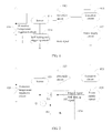
FIG.1 is a schematic structural diagram of a thermal protection circuit according to an embodiment of the present invention; -
FIG.2 is a schematic structural diagram of a thermal protection circuit according to another embodiment of the present invention; and -
FIG. 3 is a schematic distribution diagram of another sensor according to still another embodiment of the present invention. - The following clearly and completely describes the technical solutions in the embodiments of the present invention with reference to the accompanying drawings in the embodiments of the present invention. Apparently, the described embodiments are merely a part rather than all of the embodiments of the present invention. All other embodiments obtained by a person of ordinary skill in the art based on the embodiments of the present invention without creative efforts shall fall within the protection scope of the present invention.
- An embodiment of the present invention provides a thermal protection circuit 01, and as shown in
FIG. 1 , the thermal protection circuit 01 includes at least onetemperature sensor 011, adetection circuit 012, anexecution circuit 013, a self-locking and triggeringcircuit 014, and apower supply circuit 015. - There may be at least one
temperature sensor 011 which is configured to convert a temperature signal into an electrical signal and send the electrical signal to thedetection circuit 012. - The
detection circuit 012 is configured to: detect, according to the electrical signal received from thetemperature sensor 011, whether temperature reaches a preset threshold, and send a turn-off signal to the execution circuit if the temperature reaches the preset threshold; - The
execution circuit 013 is configured to cut off power supply to a system after receiving the turn-off signal from thedetection circuit 012. - The self-locking and triggering
circuit 014 is configured to maintain, after the power supply to the system is cut off, a power-off state of the system until a power switch is triggered. - The
power supply circuit 015 is a load circuit borne on the thermal protection circuit 01. - In addition, the thermal protection circuit may further include a protective
temperature regulation circuit 016 that is configured to adjust a preset temperature threshold, where thetemperature regulation circuit 016 may be a component such as a variable resistor, and the preset temperature threshold may be adjusted flexibly by changing a resistance of the variable resistor. - This embodiment of the present invention provides a thermal protection circuit 01 that cuts off power supply to a system automatically when temperature of the system is too high, and a method of the thermal protection circuit 01 is that: at least one
temperature sensor 011 converts a temperature signal into an electrical signal and sends the electrical signal to adetection circuit 012; thedetection circuit 012 detects, according to the electrical signal, whether the temperature reaches a preset temperature threshold and sends a turn-off signal to anexecution circuit 013 if the temperature reaches the preset temperature threshold; theexecution circuit 013 cuts off power supply to the system; and a self-locking and triggeringcircuit 014 maintains, after the power supply to the system is cut off, a power-off state of the system until a power switch is triggered. The thermal protection circuit 01 may further include a protectivetemperature regulation circuit 016 that adjusts the preset temperature threshold flexibly. Temperature of multiple locations can be detected simultaneously, and the preset temperature threshold can be adjusted flexibly, thereby improving system reliability. - Another embodiment of the present invention provides a thermal protection circuit 02, and as shown in
FIG. 2 , the thermal protection circuit 02 includes: at least onetemperature sensor 021, adetection circuit 022, anexecution circuit 023, a self-locking and triggeringcircuit 024, and apower supply circuit 025, and may further includes a protectivetemperature regulation circuit 026. - The
temperature sensor 021 is disposed outside a protected component, and a distance between thetemperature sensor 021 and the protected component is within a specified range, so that the protected component is within a detection range of thetemperature sensor 021. - The self-locking and triggering
circuit 024 may include: a first diode D1, a second diode D2, a field effect transistor Q, a first resistor R1 and a power switch K. - A first end of the field effect transistor Q is connected to the
sensor 021, a second end of the field effect transistor Q is connected to the power supply circuit, a third end and a forth end of the field effect transistor Q are grounded, and the first resistor R1 is connected to a connection point between the field effect transistor and thepower supply circuit 025. - A cathode of the first diode D1 is oppositely connected to a cathode of the second diode D2, an anode of the first diode D1 is connected to a connection point between the
sensor 021 and the field effect transistor Q, an anode of the second diode D2 is connected to thepower supply circuit 025, and the power switch K is connected to a connection point between the cathode of the first diode D1 and the cathode of the second diode D2. - Exemplarily, when the field effect transistor Q is an N-channel field effect transistor, a gate (G electrode) of the N-channel field effect transistor is connected to a processor in the
power supply circuit 025 or a power source, a drain (D electrode) of the N-channel field effect transistor is connected to themultiple sensors 021, and a source (S electrode) and a shielding electrode of the N-channel field effect transistor are grounded. - The
detection circuit 022 may include a comparing component, and the comparing component may be an operational amplifier, a comparator, a microcontroller, or the like. - A first input end of the comparing component is connected to the protective
temperature regulation circuit 026, a second input end of the comparing component is connected to thetemperature sensor 021, and an output end of the comparing component is connected to theexecution circuit 023. - The
execution circuit 023 may include: a field effect transistor or a load-switch. - A first end of the
execution circuit 023 is connected to thedetection circuit 022, a second end of theexecution circuit 023 is connected to thepower supply circuit 025 in which the protected component in the system is located, and a third end of theexecution circuit 023 is connected to the power source. - The
execution circuit 023 is connected to thedetection circuit 022 to form a loop, and after theexecution circuit 023 processes a signal detected by thedetection circuit 022, theexecution circuit 023 may be controlled to start or cut off power supply to thepower supply circuit 025. - The protective
temperature regulation circuit 026 may be a component such as a variable resistor, so that a preset temperature threshold can be adjusted flexibly by changing a resistance value of the variable resistor. - An operating principle of the thermal protection circuit 02 is that: at least one temperature sensor converts a temperature signal into an electrical signal, where the electrical signal is a signal used to indicate voltage, and sends the electrical signal to the
detection circuit 022; the detection circuit detects, according to the electrical signal sent by the temperature sensor, whether temperature reaches a preset threshold; when the temperature is within a range of the preset threshold, thedetection circuit 022 takes no action, and the system works normally; when the temperature reaches the preset threshold, thedetection circuit 022 sends a turn-off signal to theexecution circuit 023, theexecution circuit 023 cuts off power supply to the system after receiving the turn-off signal from thedetection circuit 022, and the self-locking and triggeringcircuit 024 is configured to maintain, after the power supply to the system is cut off, a power-off state of the system until the power switch is triggered to start power supply to the system. In this way, the hardware-based thermal protection circuit 02 can detect temperature of multiple locations simultaneously, and cut off power supply automatically when the temperature is too high, thereby improving system reliability. - Exemplarily, the
temperature sensor 021 may be formed by multiple sensors, and the multiple sensors are distributed at key positions (key chips) of a PCB (Printed Circuit Board, printed circuit board), as shown inFIG. 3 . The multiple sensors are connected in parallel, and when temperature of one of the sensors exceeds the preset temperature threshold or when temperature of N sensors reaches the preset temperature threshold simultaneously, the system may start a protection action, which is beneficial for providing protection for the entire system. For example, the preset temperature threshold is set to 95 degrees, and when one sensor detects that temperature of a chip in the power supply circuit exceeds 95 degrees, the thermal protection circuit starts a protection action; or when three of the sensors detect simultaneously that temperature of a chip reaches 95 degrees, the thermal protection circuit starts a protection action. Generally, N may be 3, or may be another value, and no limitation is imposed herein. The temperature sensor may be an NTC (Negative Temperature Coefficient, negative temperature coefficient) thermistor, a PTC (Positive Temperature Coefficient, positive temperature coefficient) thermistor, a semiconductor sensor, or the like. The number of sensors may be one or more, and in this way, temperature of the multiple locations on the PCB (Printed Circuit Board, printed circuit board) may be detected simultaneously. The larger number of sensors indicates a larger protection scope and more detailed temperature detection. - The
detection circuit 022 may be implemented by using hardware, for example, an applied comparing component may be a differential amplifier, a microcontroller, or the like, so that a protection failure caused by a software crash is avoided. - The
execution circuit 023 is generally formed by a MOS-FET (Metal-Oxide-Semiconductor -Field-Effect transistor, metal-oxide-semiconductor field-effect transistor) or a Load-Switch (load-switch). When the system works normally, the MOS-FET or the Load-Switch is on to normally provide power supply for the system; and when the temperature of the system reaches the preset threshold, the MOS-FET or the Load-Switch is shut down automatically under the control of the detection circuit, so as to cut off power supply to the chip of the system. - After the power supply to the system is cut off, the self-locking and triggering
circuit 024 may maintain the power-off state to avoid that: power supply to the system is restarted because of a decrease of the temperature, and the temperature is caused to rise again, thereby resulting in a cycle. Specifically, after temperature detected by at least one sensor of the temperature sensors reaches the preset temperature threshold and the power supply to the system is therefore cut off, the self-locking and triggeringcircuit 024 withdraws a self-locking signal from thepower supply circuit 025 to maintain the system is in the power-off state. That the system is restarted to enter a cyclic state because of a decrease of the temperature is avoided, unless a user retriggers the power switch. - Secondly, the self-locking and triggering
circuit 024 may further ensure that the system is powered on to work normally. The field effect transistor Q may implement a self-locking function of a self-locking circuit, so that the thermal protection circuit is in an on state. The first diode D1 and the second diode D2 play a role of connection, and may further prevent improper flowing of a circuit between the self-locking circuit and thepower supply circuit 025. Specifically, after thepower supply circuit 025 is powered on to work, a hold signal is output to the field effect transistor Q, so that the field effect transistor Q may implement the self-locking function of the self-locking circuit. The hold signal herein may be sent to the field effect transistor by the processor in thepower supply circuit 025 or IO (input output) of another similar element. - When the system needs to be powered on again, the field effect transistor Q in the self-locking and triggering
circuit 024 is turned on when the power switch K is pressed, to implement the self-locking function, and outputs a reference level to thedetection circuit 022. When the power supply to the system is cut off and thepower supply circuit 025 detects that a user is about to shut down the system, an IO state of the processor in the power supply circuit changes the field effect transistor Q from an on state to an off state, that is, the power supply circuit withdraws the self-locking signal, the field effect transistor Q is released, and the power supply circuit is powered off to enter a standby state, and waits to be triggered and powered on again. The first diode D1 and the second diode D2 further play a role of preventing a current from flowing backwards. - It can be learned that a trigger circuit is configured to trigger a process from a shutdown of the system to starting of the system, and the self-locking circuit is in charge of maintaining the system running and implementing a process from the starting of the system to the shutdown of the system.
- According to the foregoing descriptions, the thermal protection circuit of the present invention may include three working states: a shutdown state, an in-operation state, and a protection state. The shutdown state may be that: after the system is shut down, the self-locking and triggering
circuit 024 controls thedetection circuit 022 to adjust automatically a state of the detection circuit, so that thedetection circuit 022 turns off the MOS-FET or the Load-Switch in theexecution circuit 023. In this case, thepower supply circuit 025 is powered off. In the shutdown state, only the hardware-based thermal protection circuit 02 works, and thepower supply circuit 025 is powered off. In this way, a leakage current may be reduced, which is particularly important to a battery device and can effectively increase a storage time during a shutdown. When the power supply circuit, namely a protected circuit, is powered off, a possible short circuit risk can be avoided, so that the system can be more secure. - Exemplarily, when triggering turning off of the power switch, the user presses the power switch K. When detecting that the user is about to perform a shutdown, the
power supply circuit 025 first saves a setting such as data storage, and then changes strength of a control signal of the self-locking and triggeringcircuit 024 from high to low, where the power supply circuit may control a self-locking signal by using IO of the processor, so that the field effect transistor Q is changed from the on state to the off state. The self-locking and triggeringcircuit 024 outputs a turn-off signal to thedetection circuit 022, so that a state of thedetection circuit 022 is changed accordingly. Thedetection circuit 022 outputs the turn-off signal to theexecution circuit 023, and theexecution circuit 023 cuts off the power supply to the power supply circuit. In this case, the entire protection circuit returns to a state that is before the system is started. When the system is in the shutdown state, only the thermal protection circuit works, and the power supply circuit is powered off; or neither of the thermal protection circuit and the power supply circuit works. - The in-operation state is that: after the power switch K in the self-locking and triggering
circuit 025 is triggered to be closed, thepower supply circuit 025 may be powered on and work. Before the switch K that triggers the system to be powered on is released, the first diode D1 and the second diode D2 that are in the self-locking and triggering circuit are on, and a trigger signal is sent to the power supply circuit, an IO port of the processor or of another processor-like element in the power supply circuit outputs a hold signal to the field effect transistor Q in the self-locking and triggering circuit to maintain a system-is-on state, where the system-is-on state may be maintained by providing a specific reference level to the comparing component in thedetection circuit 022 by means of on or off of the field effect transistor Q, or may be maintained in another manner, and no limitation is imposed herein. After thepower supply circuit 025 outputs the hold signal, the switch K that triggers the system to be powered on may be released, and the system completes a power-on process and works normally. - When the field effect transistor Q is an NMOS (enhanced N-channel field effect transistor), the field effect transistor Q is on when a G electrode (gate) of the field effect transistor Q is at a high level, so that the hold signal herein may be at a high level. When the field effect transistor Q is a PMOS (enhanced P-channel field effect transistor), the hold signal may also be at a low level, and no limitation is imposed herein. There are four ends of connection points in the
power supply circuit 022. A first end is grounded. A second end is connected to the diode in the self-locking and triggering circuit, and is configured to output the hold signal to the self-locking and triggering circuit. A third end is a to-be-triggered system starting end, is connected to the field effect transistor in the self-locking and triggering circuit, and is configured to be triggered, by the field effect transistor, to be powered on. The forth end is a power supply end and connected to theexecution circuit 023, where theexecution circuit 023 controls power-on and power-off of thepower supply circuit 022. - The protection state may be that: the
temperature sensor 021 converts a temperature signal into a voltage signal, and sends the voltage signal to thedetection circuit 022. If thedetection circuit 022 detects, according to the voltage signal received from the temperature sensor, the temperature reaches the preset threshold, thedetection circuit 022 is triggered and send a turn-off signal to the MOS-FET or the Load-Switch in the execution circuit, so that the MOS-FET or Load-Switch is turned off, and the system enters the shutdown state. Therefore, a system-is-off state is maintained. Unless the user closes the switch K again to trigger power-on of the system, the system is not automatically powered on again even if the temperature of the system decreases below the preset threshold. In this way, a cycle of overtemperature - off - cooling - starting - overtemperature - off ... can be avoided. - This embodiment of the present invention provides a thermal protection circuit, and the thermal protection circuit includes: at least one temperature sensor that is configured to detect temperature of multiple locations simultaneously, convert a temperature signal into an electrical signal, and send the electrical signal to a detection circuit; the detection circuit detects, according to the electrical signal, whether the temperature reaches a preset threshold, and sends a turn-off signal to an execution circuit if the temperature reaches the preset threshold; and the execution circuit cuts off power supply to a system. A self-locking and triggering circuit can ensure normal power-on and power-off of the system, and maintain, after the system is powered off due to overtemperature, a power-off state of the system until a power switch is triggered. The thermal protection circuit may further include a protective temperature regulation circuit, so that a preset temperature threshold may be adjusted flexibly by changing a variable resistor. In this way, the thermal protection circuit can avoid low reliability of software-based protection in a hardware-based protection manner, can detect temperature of multiple locations simultaneously, and can adjust the preset temperature threshold flexibly, thereby improving system reliability.
- In the several embodiments provided in the present application, it should be understood that the disclosed circuit may be implemented in other manners. For example, the described device embodiment is merely exemplary. For example, unit division is merely logical function division and may be other division in actual implementation. For example, a plurality of units or components may be combined or integrated into another system, or some features may be ignored or not performed. In addition, the displayed or discussed mutual couplings or direct couplings or communication connections may be implemented through some interfaces. The indirect couplings or communication connections between the apparatuses or units may be implemented in electronic, mechanical, or other forms.
- In addition, function units in the embodiments of the present invention may be integrated into one processing unit, or each of the units may exist alone physically, or two or more units are integrated into one unit. The foregoing units may be implemented in a form of hardware, or may be implemented in a form of hardware in addition to a software function unit.
- The foregoing descriptions are merely specific implementation manners of the present invention, but are not intended to limit the protection scope of the present invention. Any variation or replacement readily figured out by a person skilled in the art within the technical scope disclosed in the present invention shall fall within the protection scope of the present invention. Therefore, the protection scope of the present invention shall be subject to the protection scope of the claims.
Claims (6)
- A thermal protection circuit, wherein the circuit comprises:at least one temperature sensor, configured to convert a temperature signal into an electrical signal, and send the electrical signal to a detection circuit;the detection circuit, configured to: detect, according to the electrical signal received from the temperature sensor, whether temperature reaches a preset threshold, and send a turn-off signal to an execution circuit if the temperature reaches the preset threshold;the execution circuit, configured to cut off power supply to a system after receiving the turn-off signal from the detection circuit; anda self-locking and triggering circuit, configured to maintain, after the power supply to the system is cut off, a power-off state of the system until a power switch is triggered.
- The thermal protection circuit according to claim 1, wherein the temperature sensor is disposed outside a protected component, and a distance between the temperature sensor and the protected component is within a specified range, so that the protected component is within a monitoring range of the temperature sensor.
- The thermal protection circuit according to claim 1 or 2, wherein the self-locking and triggering circuit comprises: a first diode, a second diode, a field effect transistor, a first resistor, and the power switch;
a first end of the field effect transistor is connected to the temperature sensor, a second end of the field effect transistor is connected to the power supply circuit, a third end and a forth end of the field effect transistor are grounded, and the first resistor is connected to a connection point between the field effect transistor and the power supply circuit; and
a cathode of the first diode is oppositely connected to a cathode of the second diode, an anode of the first diode is connected to a connection point between the temperature sensor and the field effect transistor, an anode of the second diode is connected to the power supply circuit, and the power switch is connected to a connection point between the cathode of the first diode and the cathode of the second diode. - The thermal protection circuit according to any one of claims 1 to 3, wherein the detection circuit comprises: a comparing component, and the comparing component is an operational amplifier, a comparator, or a microcontroller; and
a first input end of the comparing component is connected to a protective temperature regulation circuit, a second input end of the comparing component is connected to the temperature sensor, and an output end of the comparing component is connected to the execution circuit. - The thermal protection circuit according to any one of claims 1 to 4, wherein the execution circuit comprises: a field effect transistor or a load-switch; and
a first end of the execution circuit is connected to the detection circuit, a second end of the execution circuit is connected to the power supply circuit in which the protected component in the system is located, and a third end of the execution circuit is connected to a power source. - The thermal protection circuit according to any one of claims 1 to 5, further comprising: the protective temperature regulation circuit, so that the preset threshold is adjustable.
Applications Claiming Priority (2)
| Application Number | Priority Date | Filing Date | Title |
|---|---|---|---|
| CN201310119670.0A CN104104064B (en) | 2013-04-08 | 2013-04-08 | A kind of thermal protection circuit |
| PCT/CN2014/073418 WO2014166325A1 (en) | 2013-04-08 | 2014-03-14 | Thermal protection circuit |
Publications (3)
| Publication Number | Publication Date |
|---|---|
| EP2919345A1 true EP2919345A1 (en) | 2015-09-16 |
| EP2919345A4 EP2919345A4 (en) | 2016-01-20 |
| EP2919345B1 EP2919345B1 (en) | 2018-02-21 |
Family
ID=51671981
Family Applications (1)
| Application Number | Title | Priority Date | Filing Date |
|---|---|---|---|
| EP14782412.2A Active EP2919345B1 (en) | 2013-04-08 | 2014-03-14 | Thermal protection circuit |
Country Status (5)
| Country | Link |
|---|---|
| US (1) | US9819172B2 (en) |
| EP (1) | EP2919345B1 (en) |
| JP (1) | JP6055558B2 (en) |
| CN (1) | CN104104064B (en) |
| WO (1) | WO2014166325A1 (en) |
Families Citing this family (21)
| Publication number | Priority date | Publication date | Assignee | Title |
|---|---|---|---|---|
| JP5992958B2 (en) * | 2014-06-14 | 2016-09-14 | レノボ・シンガポール・プライベート・リミテッド | Method, power supply system, and computer for improving safety of voltage regulator |
| CN104300510A (en) * | 2014-11-05 | 2015-01-21 | 四川鑫远志空间信息科技有限公司 | Lithium battery protection board circuit based on zero-ohm resistance element |
| CN106371476B (en) * | 2015-07-23 | 2020-01-17 | 西安中兴新软件有限责任公司 | Terminal and method for controlling temperature of terminal |
| CN105204954B (en) * | 2015-09-17 | 2019-02-22 | Oppo广东移动通信有限公司 | A kind of method and terminal handling crash state |
| CN105226608B (en) * | 2015-10-30 | 2018-05-11 | 深圳市共进电子股份有限公司 | A kind of overheating protection circuit and set-top box |
| CN105610125B (en) * | 2015-12-24 | 2019-05-10 | 深圳市共进电子股份有限公司 | Network equipment overheating protection circuit |
| CN105610126B (en) * | 2015-12-24 | 2019-04-26 | 深圳市共进电子股份有限公司 | Network equipment overheating protection circuit |
| CN105552836A (en) * | 2016-01-22 | 2016-05-04 | 重庆大唐国际武隆水电开发有限公司 | Bearing bush temperature protection system of hydraulic power plant and protection method |
| CN106453105A (en) * | 2016-10-13 | 2017-02-22 | 成都格瑞思文化传播有限公司 | Wireless router based on wireless power supply |
| CN106830228A (en) * | 2017-03-23 | 2017-06-13 | 东莞市特纯膜环保科技有限公司 | A kind of EDI membrane stacks for preventing dry combustion method and error-polarity connection |
| DE102017214205A1 (en) | 2017-08-15 | 2019-02-21 | Robert Bosch Gmbh | Control unit with circuit and method for short-circuit protection of ground lines and sensors |
| TWI677155B (en) * | 2018-10-02 | 2019-11-11 | 新唐科技股份有限公司 | Power driving chip and method |
| CN111059038A (en) * | 2018-10-16 | 2020-04-24 | 安徽美芝制冷设备有限公司 | Temperature protection device and method for compressor, compressor system and refrigeration equipment |
| CN110320952A (en) * | 2019-07-22 | 2019-10-11 | 苏州欧普照明有限公司 | A kind of thermal-shutdown circuit and system |
| CN110303920A (en) * | 2019-07-31 | 2019-10-08 | 南京康尼新能源汽车零部件有限公司 | AC charging attachment device and temperature protecting method |
| CN110367937A (en) * | 2019-08-12 | 2019-10-25 | 苏州佳世达光电有限公司 | Oral cavity scanning machine |
| CN112329077A (en) * | 2020-11-05 | 2021-02-05 | 广州朗国电子科技有限公司 | Conference education all-in-one machine, high-temperature protection method and device and storage medium |
| CN112650128A (en) * | 2020-12-29 | 2021-04-13 | 无锡众星微系统技术有限公司 | Automatic protection method and device for chip overheating |
| CN113204466B (en) * | 2021-04-29 | 2022-11-18 | 山东英信计算机技术有限公司 | Over-temperature protection method and electronic equipment |
| US20230367376A1 (en) * | 2022-05-10 | 2023-11-16 | Apple Inc. | Systems and methods for thermal management using a mixed topology switching regulator |
| CN115588965B (en) * | 2022-11-11 | 2023-03-17 | 上海芯龙半导体技术股份有限公司南京分公司 | Over-temperature protection circuit and over-temperature protection chip |
Family Cites Families (10)
| Publication number | Priority date | Publication date | Assignee | Title |
|---|---|---|---|---|
| JP3056837B2 (en) * | 1991-07-25 | 2000-06-26 | 株式会社リコー | Fixing temperature control device |
| JPH0588142U (en) * | 1992-04-21 | 1993-11-26 | 株式会社富士通ゼネラル | Electronic device protection circuit |
| US5798667A (en) * | 1994-05-16 | 1998-08-25 | At&T Global Information Solutions Company | Method and apparatus for regulation of power dissipation |
| US5600575A (en) * | 1994-10-05 | 1997-02-04 | Anticole; Robert B. | Drive protection monitor for motor and amplifier |
| JP3241279B2 (en) | 1996-11-14 | 2001-12-25 | 株式会社日立製作所 | Switch circuit with protection function |
| US6555796B1 (en) * | 2001-11-13 | 2003-04-29 | Sherwood-Templeton Coal Company, Inc. | Heater having over temperature control |
| ITAN20030039A1 (en) | 2003-08-04 | 2005-02-05 | Merloni Termosanitari Spa | ELECTRONIC THERMOPROTECTOR FOR ELECTRIC WATER HEATERS. |
| CN2924879Y (en) * | 2005-12-16 | 2007-07-18 | 代建华 | Long-distance temperature measuring control protection device with prewarning function |
| JP5122750B2 (en) * | 2006-02-23 | 2013-01-16 | パナソニック株式会社 | Electric tool |
| CN201146378Y (en) * | 2007-12-21 | 2008-11-05 | 比亚迪股份有限公司 | Protective circuit for charging battery |
-
2013
- 2013-04-08 CN CN201310119670.0A patent/CN104104064B/en active Active
-
2014
- 2014-03-14 WO PCT/CN2014/073418 patent/WO2014166325A1/en active Application Filing
- 2014-03-14 JP JP2015551120A patent/JP6055558B2/en not_active Expired - Fee Related
- 2014-03-14 EP EP14782412.2A patent/EP2919345B1/en active Active
-
2015
- 2015-06-29 US US14/753,245 patent/US9819172B2/en active Active
Also Published As
| Publication number | Publication date |
|---|---|
| CN104104064B (en) | 2017-12-29 |
| EP2919345B1 (en) | 2018-02-21 |
| CN104104064A (en) | 2014-10-15 |
| WO2014166325A1 (en) | 2014-10-16 |
| US9819172B2 (en) | 2017-11-14 |
| JP2016511454A (en) | 2016-04-14 |
| US20150303679A1 (en) | 2015-10-22 |
| JP6055558B2 (en) | 2016-12-27 |
| EP2919345A4 (en) | 2016-01-20 |
Similar Documents
| Publication | Publication Date | Title |
|---|---|---|
| US9819172B2 (en) | Thermal protection circuit | |
| EP2966743B1 (en) | Protection device and method for preventing power source voltage of microcontroller from dropping in electronic cigarette | |
| KR101515849B1 (en) | Automatic detection of a cmos device in a latch-up and cycling of a power thereto | |
| US9307145B2 (en) | Video camera with temperature sensor | |
| US20150362982A1 (en) | Server system and cluster system using the same | |
| US9684362B2 (en) | Battery powered device | |
| US9985447B2 (en) | Battery device | |
| EP2400368B1 (en) | Power cut-off based on current | |
| EP2782202B1 (en) | Protection method of electronic device and electronic device | |
| US9420657B2 (en) | Flat panel electronic device and current control system thereof | |
| KR102103594B1 (en) | Power supply apparatus with soft―start and protection | |
| KR20140078540A (en) | Charging and discharging control circuit and battery device | |
| KR101282137B1 (en) | Portable device and method of controlling thereof | |
| TWI502853B (en) | Short circuit control for high current pulse power supply | |
| US9525296B2 (en) | Battery state monitoring circuit and battery device | |
| US10923943B2 (en) | Battery powered device with pre-powered circuit | |
| US10804717B1 (en) | Resettable battery disconnect device | |
| JP2010220277A (en) | Abnormal voltage protection circuit | |
| TWI545863B (en) | Battery protection system and battery protection method | |
| JP2012095438A (en) | Charge/discharge control circuit and battery device | |
| CN110646744A (en) | Detection circuit and power supply device | |
| RU109882U1 (en) | VOLTAGE PROTECTION DEVICE | |
| JP2017505427A (en) | Sensor element with overvoltage protection | |
| US10069059B2 (en) | Method and apparatus for shake awake smart battery pack | |
| CN220798085U (en) | Over-temperature protection circuit |
Legal Events
| Date | Code | Title | Description |
|---|---|---|---|
| PUAI | Public reference made under article 153(3) epc to a published international application that has entered the european phase |
Free format text: ORIGINAL CODE: 0009012 |
|
| 17P | Request for examination filed |
Effective date: 20150602 |
|
| AK | Designated contracting states |
Kind code of ref document: A1 Designated state(s): AL AT BE BG CH CY CZ DE DK EE ES FI FR GB GR HR HU IE IS IT LI LT LU LV MC MK MT NL NO PL PT RO RS SE SI SK SM TR |
|
| AX | Request for extension of the european patent |
Extension state: BA ME |
|
| RA4 | Supplementary search report drawn up and despatched (corrected) |
Effective date: 20151217 |
|
| RIC1 | Information provided on ipc code assigned before grant |
Ipc: H02H 7/18 20060101AFI20151211BHEP Ipc: H02H 5/04 20060101ALI20151211BHEP |
|
| DAX | Request for extension of the european patent (deleted) | ||
| GRAP | Despatch of communication of intention to grant a patent |
Free format text: ORIGINAL CODE: EPIDOSNIGR1 |
|
| RIC1 | Information provided on ipc code assigned before grant |
Ipc: H02H 7/18 20060101AFI20170802BHEP Ipc: H02H 5/04 20060101ALI20170802BHEP |
|
| INTG | Intention to grant announced |
Effective date: 20170831 |
|
| RAP1 | Party data changed (applicant data changed or rights of an application transferred) |
Owner name: HUAWEI DEVICE (DONGGUAN) CO., LTD. |
|
| GRAS | Grant fee paid |
Free format text: ORIGINAL CODE: EPIDOSNIGR3 |
|
| GRAA | (expected) grant |
Free format text: ORIGINAL CODE: 0009210 |
|
| AK | Designated contracting states |
Kind code of ref document: B1 Designated state(s): AL AT BE BG CH CY CZ DE DK EE ES FI FR GB GR HR HU IE IS IT LI LT LU LV MC MK MT NL NO PL PT RO RS SE SI SK SM TR |
|
| REG | Reference to a national code |
Ref country code: GB Ref legal event code: FG4D |
|
| REG | Reference to a national code |
Ref country code: FR Ref legal event code: PLFP Year of fee payment: 5 |
|
| REG | Reference to a national code |
Ref country code: CH Ref legal event code: EP |
|
| REG | Reference to a national code |
Ref country code: AT Ref legal event code: REF Ref document number: 972708 Country of ref document: AT Kind code of ref document: T Effective date: 20180315 |
|
| REG | Reference to a national code |
Ref country code: IE Ref legal event code: FG4D |
|
| REG | Reference to a national code |
Ref country code: DE Ref legal event code: R096 Ref document number: 602014021314 Country of ref document: DE |
|
| REG | Reference to a national code |
Ref country code: NL Ref legal event code: MP Effective date: 20180221 |
|
| REG | Reference to a national code |
Ref country code: LT Ref legal event code: MG4D |
|
| REG | Reference to a national code |
Ref country code: AT Ref legal event code: MK05 Ref document number: 972708 Country of ref document: AT Kind code of ref document: T Effective date: 20180221 |
|
| PG25 | Lapsed in a contracting state [announced via postgrant information from national office to epo] |
Ref country code: HR Free format text: LAPSE BECAUSE OF FAILURE TO SUBMIT A TRANSLATION OF THE DESCRIPTION OR TO PAY THE FEE WITHIN THE PRESCRIBED TIME-LIMIT Effective date: 20180221 Ref country code: FI Free format text: LAPSE BECAUSE OF FAILURE TO SUBMIT A TRANSLATION OF THE DESCRIPTION OR TO PAY THE FEE WITHIN THE PRESCRIBED TIME-LIMIT Effective date: 20180221 Ref country code: NO Free format text: LAPSE BECAUSE OF FAILURE TO SUBMIT A TRANSLATION OF THE DESCRIPTION OR TO PAY THE FEE WITHIN THE PRESCRIBED TIME-LIMIT Effective date: 20180521 Ref country code: CY Free format text: LAPSE BECAUSE OF FAILURE TO SUBMIT A TRANSLATION OF THE DESCRIPTION OR TO PAY THE FEE WITHIN THE PRESCRIBED TIME-LIMIT Effective date: 20180221 Ref country code: ES Free format text: LAPSE BECAUSE OF FAILURE TO SUBMIT A TRANSLATION OF THE DESCRIPTION OR TO PAY THE FEE WITHIN THE PRESCRIBED TIME-LIMIT Effective date: 20180221 Ref country code: LT Free format text: LAPSE BECAUSE OF FAILURE TO SUBMIT A TRANSLATION OF THE DESCRIPTION OR TO PAY THE FEE WITHIN THE PRESCRIBED TIME-LIMIT Effective date: 20180221 Ref country code: NL Free format text: LAPSE BECAUSE OF FAILURE TO SUBMIT A TRANSLATION OF THE DESCRIPTION OR TO PAY THE FEE WITHIN THE PRESCRIBED TIME-LIMIT Effective date: 20180221 |
|
| PG25 | Lapsed in a contracting state [announced via postgrant information from national office to epo] |
Ref country code: AT Free format text: LAPSE BECAUSE OF FAILURE TO SUBMIT A TRANSLATION OF THE DESCRIPTION OR TO PAY THE FEE WITHIN THE PRESCRIBED TIME-LIMIT Effective date: 20180221 Ref country code: RS Free format text: LAPSE BECAUSE OF FAILURE TO SUBMIT A TRANSLATION OF THE DESCRIPTION OR TO PAY THE FEE WITHIN THE PRESCRIBED TIME-LIMIT Effective date: 20180221 Ref country code: SE Free format text: LAPSE BECAUSE OF FAILURE TO SUBMIT A TRANSLATION OF THE DESCRIPTION OR TO PAY THE FEE WITHIN THE PRESCRIBED TIME-LIMIT Effective date: 20180221 Ref country code: LV Free format text: LAPSE BECAUSE OF FAILURE TO SUBMIT A TRANSLATION OF THE DESCRIPTION OR TO PAY THE FEE WITHIN THE PRESCRIBED TIME-LIMIT Effective date: 20180221 Ref country code: BG Free format text: LAPSE BECAUSE OF FAILURE TO SUBMIT A TRANSLATION OF THE DESCRIPTION OR TO PAY THE FEE WITHIN THE PRESCRIBED TIME-LIMIT Effective date: 20180521 Ref country code: GR Free format text: LAPSE BECAUSE OF FAILURE TO SUBMIT A TRANSLATION OF THE DESCRIPTION OR TO PAY THE FEE WITHIN THE PRESCRIBED TIME-LIMIT Effective date: 20180522 |
|
| PG25 | Lapsed in a contracting state [announced via postgrant information from national office to epo] |
Ref country code: RO Free format text: LAPSE BECAUSE OF FAILURE TO SUBMIT A TRANSLATION OF THE DESCRIPTION OR TO PAY THE FEE WITHIN THE PRESCRIBED TIME-LIMIT Effective date: 20180221 Ref country code: AL Free format text: LAPSE BECAUSE OF FAILURE TO SUBMIT A TRANSLATION OF THE DESCRIPTION OR TO PAY THE FEE WITHIN THE PRESCRIBED TIME-LIMIT Effective date: 20180221 Ref country code: IT Free format text: LAPSE BECAUSE OF FAILURE TO SUBMIT A TRANSLATION OF THE DESCRIPTION OR TO PAY THE FEE WITHIN THE PRESCRIBED TIME-LIMIT Effective date: 20180221 Ref country code: EE Free format text: LAPSE BECAUSE OF FAILURE TO SUBMIT A TRANSLATION OF THE DESCRIPTION OR TO PAY THE FEE WITHIN THE PRESCRIBED TIME-LIMIT Effective date: 20180221 Ref country code: PL Free format text: LAPSE BECAUSE OF FAILURE TO SUBMIT A TRANSLATION OF THE DESCRIPTION OR TO PAY THE FEE WITHIN THE PRESCRIBED TIME-LIMIT Effective date: 20180221 |
|
| REG | Reference to a national code |
Ref country code: CH Ref legal event code: PL |
|
| REG | Reference to a national code |
Ref country code: DE Ref legal event code: R097 Ref document number: 602014021314 Country of ref document: DE |
|
| PG25 | Lapsed in a contracting state [announced via postgrant information from national office to epo] |
Ref country code: SM Free format text: LAPSE BECAUSE OF FAILURE TO SUBMIT A TRANSLATION OF THE DESCRIPTION OR TO PAY THE FEE WITHIN THE PRESCRIBED TIME-LIMIT Effective date: 20180221 Ref country code: SK Free format text: LAPSE BECAUSE OF FAILURE TO SUBMIT A TRANSLATION OF THE DESCRIPTION OR TO PAY THE FEE WITHIN THE PRESCRIBED TIME-LIMIT Effective date: 20180221 Ref country code: MC Free format text: LAPSE BECAUSE OF FAILURE TO SUBMIT A TRANSLATION OF THE DESCRIPTION OR TO PAY THE FEE WITHIN THE PRESCRIBED TIME-LIMIT Effective date: 20180221 Ref country code: CZ Free format text: LAPSE BECAUSE OF FAILURE TO SUBMIT A TRANSLATION OF THE DESCRIPTION OR TO PAY THE FEE WITHIN THE PRESCRIBED TIME-LIMIT Effective date: 20180221 Ref country code: DK Free format text: LAPSE BECAUSE OF FAILURE TO SUBMIT A TRANSLATION OF THE DESCRIPTION OR TO PAY THE FEE WITHIN THE PRESCRIBED TIME-LIMIT Effective date: 20180221 |
|
| REG | Reference to a national code |
Ref country code: BE Ref legal event code: MM Effective date: 20180331 |
|
| REG | Reference to a national code |
Ref country code: IE Ref legal event code: MM4A |
|
| PLBE | No opposition filed within time limit |
Free format text: ORIGINAL CODE: 0009261 |
|
| STAA | Information on the status of an ep patent application or granted ep patent |
Free format text: STATUS: NO OPPOSITION FILED WITHIN TIME LIMIT |
|
| PG25 | Lapsed in a contracting state [announced via postgrant information from national office to epo] |
Ref country code: LU Free format text: LAPSE BECAUSE OF NON-PAYMENT OF DUE FEES Effective date: 20180314 |
|
| 26N | No opposition filed |
Effective date: 20181122 |
|
| PG25 | Lapsed in a contracting state [announced via postgrant information from national office to epo] |
Ref country code: IE Free format text: LAPSE BECAUSE OF NON-PAYMENT OF DUE FEES Effective date: 20180314 |
|
| PG25 | Lapsed in a contracting state [announced via postgrant information from national office to epo] |
Ref country code: BE Free format text: LAPSE BECAUSE OF NON-PAYMENT OF DUE FEES Effective date: 20180331 Ref country code: SI Free format text: LAPSE BECAUSE OF FAILURE TO SUBMIT A TRANSLATION OF THE DESCRIPTION OR TO PAY THE FEE WITHIN THE PRESCRIBED TIME-LIMIT Effective date: 20180221 Ref country code: LI Free format text: LAPSE BECAUSE OF NON-PAYMENT OF DUE FEES Effective date: 20180331 Ref country code: CH Free format text: LAPSE BECAUSE OF NON-PAYMENT OF DUE FEES Effective date: 20180331 |
|
| REG | Reference to a national code |
Ref country code: DE Ref legal event code: R081 Ref document number: 602014021314 Country of ref document: DE Owner name: HUAWEI DEVICE CO., LTD., DONGGUAN, CN Free format text: FORMER OWNER: HUAWEI DEVICE (DONGGUAN) CO., LTD., DONGGUAN, GUANGDONG, CN |
|
| PG25 | Lapsed in a contracting state [announced via postgrant information from national office to epo] |
Ref country code: MT Free format text: LAPSE BECAUSE OF NON-PAYMENT OF DUE FEES Effective date: 20180314 |
|
| PG25 | Lapsed in a contracting state [announced via postgrant information from national office to epo] |
Ref country code: TR Free format text: LAPSE BECAUSE OF FAILURE TO SUBMIT A TRANSLATION OF THE DESCRIPTION OR TO PAY THE FEE WITHIN THE PRESCRIBED TIME-LIMIT Effective date: 20180221 |
|
| PG25 | Lapsed in a contracting state [announced via postgrant information from national office to epo] |
Ref country code: PT Free format text: LAPSE BECAUSE OF FAILURE TO SUBMIT A TRANSLATION OF THE DESCRIPTION OR TO PAY THE FEE WITHIN THE PRESCRIBED TIME-LIMIT Effective date: 20180221 |
|
| PG25 | Lapsed in a contracting state [announced via postgrant information from national office to epo] |
Ref country code: MK Free format text: LAPSE BECAUSE OF NON-PAYMENT OF DUE FEES Effective date: 20180221 Ref country code: HU Free format text: LAPSE BECAUSE OF FAILURE TO SUBMIT A TRANSLATION OF THE DESCRIPTION OR TO PAY THE FEE WITHIN THE PRESCRIBED TIME-LIMIT; INVALID AB INITIO Effective date: 20140314 |
|
| PG25 | Lapsed in a contracting state [announced via postgrant information from national office to epo] |
Ref country code: IS Free format text: LAPSE BECAUSE OF FAILURE TO SUBMIT A TRANSLATION OF THE DESCRIPTION OR TO PAY THE FEE WITHIN THE PRESCRIBED TIME-LIMIT Effective date: 20180621 |
|
| PGFP | Annual fee paid to national office [announced via postgrant information from national office to epo] |
Ref country code: FR Payment date: 20230208 Year of fee payment: 10 |
|
| PGFP | Annual fee paid to national office [announced via postgrant information from national office to epo] |
Ref country code: GB Payment date: 20230202 Year of fee payment: 10 Ref country code: DE Payment date: 20230131 Year of fee payment: 10 |