EP2919318B1 - Base station antenna feed network - Google Patents
Base station antenna feed network Download PDFInfo
- Publication number
- EP2919318B1 EP2919318B1 EP13898577.5A EP13898577A EP2919318B1 EP 2919318 B1 EP2919318 B1 EP 2919318B1 EP 13898577 A EP13898577 A EP 13898577A EP 2919318 B1 EP2919318 B1 EP 2919318B1
- Authority
- EP
- European Patent Office
- Prior art keywords
- phase shifter
- feeding network
- phase
- feeding
- transmission line
- Prior art date
- Legal status (The legal status is an assumption and is not a legal conclusion. Google has not performed a legal analysis and makes no representation as to the accuracy of the status listed.)
- Active
Links
Images


Classifications
-
- H—ELECTRICITY
- H01—ELECTRIC ELEMENTS
- H01Q—ANTENNAS, i.e. RADIO AERIALS
- H01Q21/00—Antenna arrays or systems
- H01Q21/0006—Particular feeding systems
- H01Q21/0075—Stripline fed arrays
-
- H—ELECTRICITY
- H01—ELECTRIC ELEMENTS
- H01P—WAVEGUIDES; RESONATORS, LINES, OR OTHER DEVICES OF THE WAVEGUIDE TYPE
- H01P1/00—Auxiliary devices
- H01P1/18—Phase-shifters
- H01P1/182—Waveguide phase-shifters
-
- H—ELECTRICITY
- H01—ELECTRIC ELEMENTS
- H01P—WAVEGUIDES; RESONATORS, LINES, OR OTHER DEVICES OF THE WAVEGUIDE TYPE
- H01P1/00—Auxiliary devices
- H01P1/18—Phase-shifters
- H01P1/183—Coaxial phase-shifters
-
- H—ELECTRICITY
- H01—ELECTRIC ELEMENTS
- H01P—WAVEGUIDES; RESONATORS, LINES, OR OTHER DEVICES OF THE WAVEGUIDE TYPE
- H01P1/00—Auxiliary devices
- H01P1/18—Phase-shifters
- H01P1/184—Strip line phase-shifters
-
- H—ELECTRICITY
- H01—ELECTRIC ELEMENTS
- H01P—WAVEGUIDES; RESONATORS, LINES, OR OTHER DEVICES OF THE WAVEGUIDE TYPE
- H01P3/00—Waveguides; Transmission lines of the waveguide type
- H01P3/02—Waveguides; Transmission lines of the waveguide type with two longitudinal conductors
- H01P3/08—Microstrips; Strip lines
- H01P3/081—Microstriplines
- H01P3/084—Suspended microstriplines
-
- H—ELECTRICITY
- H01—ELECTRIC ELEMENTS
- H01P—WAVEGUIDES; RESONATORS, LINES, OR OTHER DEVICES OF THE WAVEGUIDE TYPE
- H01P5/00—Coupling devices of the waveguide type
- H01P5/12—Coupling devices having more than two ports
-
- H—ELECTRICITY
- H01—ELECTRIC ELEMENTS
- H01Q—ANTENNAS, i.e. RADIO AERIALS
- H01Q3/00—Arrangements for changing or varying the orientation or the shape of the directional pattern of the waves radiated from an antenna or antenna system
- H01Q3/26—Arrangements for changing or varying the orientation or the shape of the directional pattern of the waves radiated from an antenna or antenna system varying the relative phase or relative amplitude of energisation between two or more active radiating elements; varying the distribution of energy across a radiating aperture
- H01Q3/30—Arrangements for changing or varying the orientation or the shape of the directional pattern of the waves radiated from an antenna or antenna system varying the relative phase or relative amplitude of energisation between two or more active radiating elements; varying the distribution of energy across a radiating aperture varying the relative phase between the radiating elements of an array
- H01Q3/32—Arrangements for changing or varying the orientation or the shape of the directional pattern of the waves radiated from an antenna or antenna system varying the relative phase or relative amplitude of energisation between two or more active radiating elements; varying the distribution of energy across a radiating aperture varying the relative phase between the radiating elements of an array by mechanical means
Definitions
- This disclosure generally relates to mobile communication technologies and, more particularly, to a feeding network used for electrically adjustable base station antenna.
- phase shifting device for a phase shifting device in the traditional technology, the back-and-forth movement of a metal conductor rod in a metal conductor tube is used to change the actual length of a transmission path to achieve the purpose of phase change.
- power dividers must be added for power division.
- the volume of the phase shifter normally needs to be increased, resulting in a complicated structure of the feeding network and poor electrical performance and consistence of the product.
- micro-strip type power dividers and phase shifters are used for an equal-phase difference multi-path compound phase shifter in existing technologies. Deficiencies such as high loss and unstable performance are present, especially for the length regulation mechanism of the phase shifter. So they have limited usage in mass production.
- CN 102157767 relates to a coaxial medium phase shifter.
- the phase shifter comprises an inner conductor and an outer conductor, wherein the inner conductor defines at least two parallel conduction arms and the outer conductor provides coaxial cavities for the conduction arms. Medium elements move along the axial direction of the coaxial cavities to change the phase of signals.
- CN 102157767 also describes an antenna array with five radiating elements, four separate coaxial medium phase shifters, a 3-way power splitter and two 2-way power splitters.
- CN 101707271 relates to an equiphase differential multiplexed phase shifter comprising a plurality of phase shifter subunits, a plurality of power divider subunits, a metallic reflector plate, a sliding device and a positioning device for limiting the sliding stroke.
- the phase shifter subunits are serially connected with a main circuit of the power divider subunits, and consist of fixed transmission lines and slidable transmission lines.
- This invention intends to provide with a feeding network for base station antenna with compact structure, flexible design of power division ratio, and stable performance.
- This invention cascades the various power dividers and phase shifters in a distributed way, achieving flexible design of power division ratio, stable performance, and relatively low power loss. It further optimizes the phase shifters and power dividers as well as the general structure of the feeding network, achieving compact structure of the feeding network, relatively small dimensions, ease for processing, and reduced cost.
- the wide band can be achieved easily, and the general performance and consistency are more stable. They can also be combined flexibly to increase the number of output terminals, resolving the demand for wide-band feeding network for electrically adjustable base station antenna.
- the phase shifters are based on the nest coupling principle of metal tube and can achieve excellent consistency, flexible design of power division ratio, stable performance, and relatively low power loss.
- the various functional components are assembled in a narrow and long metal cavity that is integrally formed.
- the various feeding ports are distributed along its long side.
- the functional assemblies are also set inside the cavity, overcoming the deficiencies such as complicated structure, too many welding spots, and high power loss in existing technologies. It can achieve a compact structure of the feeding network, relatively small dimensions, ease for processing, and reduced cost.
- the wide band can be achieved easily, and the general performance and consistency are more stable. Compared with other structures, it can avoid signal leakage effectively and avoid resonance points.
- the section of this metal cavity structure can be a single rectangle, a one-side-opened single rectangle, an up-down dual rectangle, an up-down one-side-opened dual rectangle, a left-right dual rectangle, a left-right one-side-opened dual rectangle, or a multi-cavity structure formed by combing two or more of the above. They can also be combined flexibly to increase the number of output terminals, resolving the demand for wide-band feeding network for electrically adjustable base station antenna.
- the power divider is composed of an air strip line in a branch form.
- the strip line is of flat, round, square or other shape, or a combination thereof.
- the single-row feeding structure is combined through a tiling and/or laminating form and can constitute a phase-shifting feeding network with more output terminals.
- the various phase shifters are identical and can achieve equidifferent phase change.
- This invention provides with a feeding network for base station antenna, which is characterized by compact structure, stable performance, flexible combination, and extremely low loss.
- This invention cascades various power dividers and phase shifters in a distributed way.
- the phase shifters are based on the nest coupling principle of metal tube, achieving excellent consistency, flexible design of power division ratio, stable performance, and relatively low power loss. It further optimizes the phase shifters and power dividers as well as the general structure of the feeding network.
- the various functional components are assembled in a narrow and long metal cavity, which is integrally formed. A plurality of feeding ports are distributed along its long side.
- the functional assemblies are also set inside the cavity, overcoming the deficiencies such as complicated structure, too many welding spots, and high power loss in existing technologies. It can achieve compact structure of the feeding network, relatively small dimensions, ease for processing, and reduced cost. Wide band can be achieved easily, and the general performance and consistency are more stable. Compared with other structures, it can avoid signal leakage effectively and avoid resonance points.
- the structures can also be combined flexibly to increase the number of output terminals, resolving the demand for wide-band feeding network for electrically adjustable base station antenna.
- the feeding network for base station antenna of this invention includes a 3-way power divider.
- the power of the feeding port input is divided equally into 3 routes through this 3-way power divider. Among them, one route is used to feed the central unit of an array, and the other two output terminals are connected with the phase shifters on the left and right sides.
- the adjacent phase shifters are cascaded through a 2-way power divider and feed the units on the left and right sides of the array, respectively.
- N phase shifters and N-1 2-way power dividers as well as N' phase shifters and N'-1 2-way power dividers are provided, respectively.
- the output terminal of the previous phase shifter is connected with the input terminal of the power divider.
- One output terminal of the power divider is used as an output terminal of the whole feeding network, and the other output terminal is connected with the input terminal of the next phase shifter.
- the power division ratio can also be set as required.
- the various phase shifters are identical except that the phase shifts of the corresponding output ports on the left and right sides are in opposite directions when the sliding rod moves along the line to form a stepped phase distribution and to control the declination of the direction diagram in the vertical plane.
- the various phase shifters are identical to achieve equidifferent phase change.
- the phase shifters and the power dividers are both placed in an integrally formed metal cavity structure.
- the various feeding points are distributed evenly along the long side of the structure.
- the various functional components are assembled in a narrow and long metal cavity, which is integrally formed.
- the various feeding ports are distributed along its long side.
- the functional assemblies are also set inside the cavity, overcoming the deficiencies such as complicated structure, too many welding spots, and high power loss in existing technologies. It can achieve compact structure of the feeding network, relatively small dimensions, ease for processing, and reduced cost. The wide band can be achieved easily, and the general performance and consistency are more stable.
- the section of this metal cavity structure is a single rectangle (as shown in Figure 2d ), one-side-opened single rectangle (as shown in Figure 2e ), up-down dual rectangle (as shown in Figure 2a ), up-down one-side-opened dual rectangle, left-right dual rectangle, left-right one-side-opened dual rectangle, or multi-cavity structure formed by combing two or more of the above.
- the power divider is an air strip line type composed in a branch form. This strip line is of flat, round, square, or other shape, or a combination of them.
- Figures 3a ⁇ 3b are structural diagrams of the central conduction bands of the power divider of the air strip line type. In Figures 3a and 3b , a is an input terminal, and b, c, & d are output terminals.
- Figure 3a is a 3-way power divider and Figure 3b is a 2-way power divider.
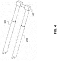
- Figure 4 is a structural diagram of the phase shifter of a deformed strip line type.
- 200 and 300 are hollow round metal tubes of fixed transmission lines.
- the moveable U-shaped metal rod 100 which is coated with an insulation medium layer on the surface, is a sliding transmission line. It is inserted into the hollow metal tubes 2 and 3, and changes the actual length of the transmission line through the moveable U-shaped metal rod 100 to adjust the phase.
- the single-row feeding structure is combined through a tiling and/or laminating form to constitute a phase-shifting feeding network with more output terminals.
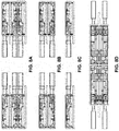
- FIG. 5 is a laminated 2-in-8-out feeding network of Embodiment 1 of this invention.
- Each layer includes 7 power dividers and 8 phase shifters, constituting 1-in-9-out feeding electronic system.
- 2-1 is an input power divider and power divider 2-2 connects phase shifters 3-1 and 3-2. They are both assembled in a metal cavity 1.
- coaxial cables are used to input the signal from terminal 4-a to the input terminal 2-1-a of power divider 2-1. It is divided into three routes, i.e., 2-1-b, 2-1-c, and 2-1-d.
- the 2-1-b route connects coaxial cable 4-c and is used as an output terminal.
- 2-1-c is connected to the input terminal 3-2-a of phase shifter 3-2. After phase shifting, it is connected through its output 3-2-b to the input terminal 2-2-a of power divider 2-2. It is divided into two routes. Its output 2-2-b route connects to coaxial cable 4-e as an output of the feeding network. The 2-2-c route is connected to the input terminal 3-1-a of phase shifter 3-1. After phase shifting, it is connected through its output terminal 3-1-b to the coaxial cable 4-g as an output.
- the principle is similar to the above description. In this way, when the phase shifting device moves, the various output terminals of the upper or lower layer can obtain a phase distribution with equidifferent phase change.
- FIG. 6 is a two-layer 2-in-10-out feeding network of Embodiment 2 of this invention.
- Each layer includes 3 power dividers and 4 phase shifters, constituting 1-input-5-output feeding electronic system.
- 2-1 is an input 3-way power divider and 2-2 is a 2-way power divider.
- This 2-way power divider 2-2 connects to phase shifter 3-1 and 3-2.
- the signal is input from a coaxial input terminal 4-f.
- power divider 2-1 it is divided into 3 routes, i.e., 2-1-b, 2-1-c, and 2-1-d.
- the 2-1-b route connects to the conductor inside the coaxial wire, forming an output terminal 4-h.
- the 2-1-c route is connected to the input terminal 3-1-a of the other phase shifter. After phase shifting, output terminal 3-1-b is connected to an input terminal 2-2-a of power divider 2-2. It is divided into 2 routes.
- the 2-2-b route connects to the conductor inside the coaxial wire, forming output terminal 4-j.
- the 2-2-c route is connected to the input terminal 3-2-a of the other phase shifter. After phase shifting, its output 3-2-b is connected to the conductor inside the coaxial wire, forming output terminal 4-1.
- the feeding electronic network structure and principle are similar to the above description.
- Figure 7 is a tiling 2-in-10-out feeding network of Embodiment 3 of this invention. Its working principle is the same as the layered structure of the embodiment shown in Figure 5 except that the arrangement of the two groups of sub-networks is different.
- Figure 8a ⁇ 8d are diagrams of the single-layer, dual-layer, tri-layer, and multi-layer combinations of the feeding network. They provide examples of feeding networks in which a row of feeding electronic networks are laminated to constitute more ports. In addition, the number of ports of the feeding network can be further increased by tiling more networks.
- Figure 9 is a diagram of the connection between the feeding network and an antenna unit.
Description
- This disclosure generally relates to mobile communication technologies and, more particularly, to a feeding network used for electrically adjustable base station antenna.
- With the development of mobile communication technologies, the requirements for electrical and mechanical performance of a base station antenna become higher and higher. High performance and miniaturization, e.g., larger electrical declination, higher efficiency, wider band, and smaller volume, become a trend in the development of base station antenna. The requirements for the performance of the feeding network for base station antenna also become higher.
- For a phase shifting device in the traditional technology, the back-and-forth movement of a metal conductor rod in a metal conductor tube is used to change the actual length of a transmission path to achieve the purpose of phase change. However, in practice, power dividers must be added for power division. Moreover, to obtain a larger phase shifting quantity, the volume of the phase shifter normally needs to be increased, resulting in a complicated structure of the feeding network and poor electrical performance and consistence of the product. In addition, for an equal-phase difference multi-path compound phase shifter in existing technologies, micro-strip type power dividers and phase shifters are used. Deficiencies such as high loss and unstable performance are present, especially for the length regulation mechanism of the phase shifter. So they have limited usage in mass production.
- Therefore, for a feeding network in existing technology, there exist deficiencies and problems such as complicated structure assembly, too many welding spots, high power loss, poor consistency, large volume, and high manufacture cost.
- Therefore, it is desirable to provide a feeding network for base station antenna with flexible design of power division ratio, compact structure, stable performance, wide working band, good consistency, low power loss, simple structure, small volume, reduced cost, and convenience for mass production.
-
CN 102157767 relates to a coaxial medium phase shifter. The phase shifter comprises an inner conductor and an outer conductor, wherein the inner conductor defines at least two parallel conduction arms and the outer conductor provides coaxial cavities for the conduction arms. Medium elements move along the axial direction of the coaxial cavities to change the phase of signals.CN 102157767 also describes an antenna array with five radiating elements, four separate coaxial medium phase shifters, a 3-way power splitter and two 2-way power splitters. -
CN 101707271 relates to an equiphase differential multiplexed phase shifter comprising a plurality of phase shifter subunits, a plurality of power divider subunits, a metallic reflector plate, a sliding device and a positioning device for limiting the sliding stroke. The phase shifter subunits are serially connected with a main circuit of the power divider subunits, and consist of fixed transmission lines and slidable transmission lines. - Document
US 2502359 discloses a phase shifter with U-shaped loops to minimize the physical size of the shifter. - In accordance with the invention, there is provided a feeding network for a base station as recited by
claim 1. - This invention intends to provide with a feeding network for base station antenna with compact structure, flexible design of power division ratio, and stable performance.
- This invention cascades the various power dividers and phase shifters in a distributed way, achieving flexible design of power division ratio, stable performance, and relatively low power loss. It further optimizes the phase shifters and power dividers as well as the general structure of the feeding network, achieving compact structure of the feeding network, relatively small dimensions, ease for processing, and reduced cost. The wide band can be achieved easily, and the general performance and consistency are more stable. They can also be combined flexibly to increase the number of output terminals, resolving the demand for wide-band feeding network for electrically adjustable base station antenna. The phase shifters are based on the nest coupling principle of metal tube and can achieve excellent consistency, flexible design of power division ratio, stable performance, and relatively low power loss.
- In this invention, the various functional components are assembled in a narrow and long metal cavity that is integrally formed. The various feeding ports are distributed along its long side. The functional assemblies are also set inside the cavity, overcoming the deficiencies such as complicated structure, too many welding spots, and high power loss in existing technologies. It can achieve a compact structure of the feeding network, relatively small dimensions, ease for processing, and reduced cost. The wide band can be achieved easily, and the general performance and consistency are more stable. Compared with other structures, it can avoid signal leakage effectively and avoid resonance points.
- Optimally, the section of this metal cavity structure can be a single rectangle, a one-side-opened single rectangle, an up-down dual rectangle, an up-down one-side-opened dual rectangle, a left-right dual rectangle, a left-right one-side-opened dual rectangle, or a multi-cavity structure formed by combing two or more of the above. They can also be combined flexibly to increase the number of output terminals, resolving the demand for wide-band feeding network for electrically adjustable base station antenna.
- Optimally, the power divider is composed of an air strip line in a branch form.
- Optimally, the strip line is of flat, round, square or other shape, or a combination thereof.
- Optimally, the single-row feeding structure is combined through a tiling and/or laminating form and can constitute a phase-shifting feeding network with more output terminals.
- Optimally, the various phase shifters are identical and can achieve equidifferent phase change.
- Compared with existing technologies, this invention has the following advantages:
This invention provides with a feeding network for base station antenna, which is characterized by compact structure, stable performance, flexible combination, and extremely low loss. This invention cascades various power dividers and phase shifters in a distributed way. The phase shifters are based on the nest coupling principle of metal tube, achieving excellent consistency, flexible design of power division ratio, stable performance, and relatively low power loss. It further optimizes the phase shifters and power dividers as well as the general structure of the feeding network. The various functional components are assembled in a narrow and long metal cavity, which is integrally formed. A plurality of feeding ports are distributed along its long side. The functional assemblies are also set inside the cavity, overcoming the deficiencies such as complicated structure, too many welding spots, and high power loss in existing technologies. It can achieve compact structure of the feeding network, relatively small dimensions, ease for processing, and reduced cost. Wide band can be achieved easily, and the general performance and consistency are more stable. Compared with other structures, it can avoid signal leakage effectively and avoid resonance points. The structures can also be combined flexibly to increase the number of output terminals, resolving the demand for wide-band feeding network for electrically adjustable base station antenna. -
-
Figure 1 is a schematic diagram of the feeding network of this invention. -
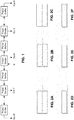
Figures 2a∼2f are sectional shape diagrams of the embodiments of the integrally formed metal cavity of this invention. -
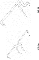
Figure 3a∼3b are structural diagrams of the power dividers used for the feeding network of this invention. -
Figure 4 is the structural diagram of the phase shifter used for the feeding network of this invention. -
Figure 5 is the structural diagram of the feeding network ofEmbodiment 1 of this invention. -
Figure 6 is the structural diagram of the feeding network of Embodiment 2 of this invention. -
Figure 7 is the structural diagram of the feeding network of Embodiment 3 of this invention. -
Figure 8a∼8d are diagrams of the single-layer, dual-layer, tri-layer, and multi-layer combination modes for the feeding network of this invention. -
Figure 9 is the diagram of the connection between the feeding network and antenna unit of this invention. - Referring to
Figure 1 , the feeding network for base station antenna of this invention includes a 3-way power divider. The power of the feeding port input is divided equally into 3 routes through this 3-way power divider. Among them, one route is used to feed the central unit of an array, and the other two output terminals are connected with the phase shifters on the left and right sides. The adjacent phase shifters are cascaded through a 2-way power divider and feed the units on the left and right sides of the array, respectively. On the two sides of the 3-way power divider inFigure 1 , N phase shifters and N-1 2-way power dividers as well as N' phase shifters and N'-1 2-way power dividers are provided, respectively. The output terminal of the previous phase shifter is connected with the input terminal of the power divider. One output terminal of the power divider is used as an output terminal of the whole feeding network, and the other output terminal is connected with the input terminal of the next phase shifter. The power division ratio can also be set as required. The various phase shifters are identical except that the phase shifts of the corresponding output ports on the left and right sides are in opposite directions when the sliding rod moves along the line to form a stepped phase distribution and to control the declination of the direction diagram in the vertical plane. In this embodiment, the various phase shifters are identical to achieve equidifferent phase change. - The phase shifters and the power dividers are both placed in an integrally formed metal cavity structure. The various feeding points are distributed evenly along the long side of the structure. The various functional components are assembled in a narrow and long metal cavity, which is integrally formed. The various feeding ports are distributed along its long side. The functional assemblies are also set inside the cavity, overcoming the deficiencies such as complicated structure, too many welding spots, and high power loss in existing technologies. It can achieve compact structure of the feeding network, relatively small dimensions, ease for processing, and reduced cost. The wide band can be achieved easily, and the general performance and consistency are more stable.
- Referring to
Figures 2a∼2f , the section of this metal cavity structure is a single rectangle (as shown inFigure 2d ), one-side-opened single rectangle (as shown inFigure 2e ), up-down dual rectangle (as shown inFigure 2a ), up-down one-side-opened dual rectangle, left-right dual rectangle, left-right one-side-opened dual rectangle, or multi-cavity structure formed by combing two or more of the above. - Referring to
Figures 3a∼3b , the power divider is an air strip line type composed in a branch form. This strip line is of flat, round, square, or other shape, or a combination of them.Figures 3a∼3b are structural diagrams of the central conduction bands of the power divider of the air strip line type. InFigures 3a and 3b , a is an input terminal, and b, c, & d are output terminals.Figure 3a is a 3-way power divider andFigure 3b is a 2-way power divider. -
Figure 4 is a structural diagram of the phase shifter of a deformed strip line type. InFigure 4 , 200 and 300 are hollow round metal tubes of fixed transmission lines. The moveableU-shaped metal rod 100, which is coated with an insulation medium layer on the surface, is a sliding transmission line. It is inserted into the hollow metal tubes 2 and 3, and changes the actual length of the transmission line through the moveableU-shaped metal rod 100 to adjust the phase. - The single-row feeding structure is combined through a tiling and/or laminating form to constitute a phase-shifting feeding network with more output terminals.
-
Figure 5 is a laminated 2-in-8-out feeding network ofEmbodiment 1 of this invention. Each layer includes 7 power dividers and 8 phase shifters, constituting 1-in-9-out feeding electronic system. (Only part of it is shown and described here.) Among them, 2-1 is an input power divider and power divider 2-2 connects phase shifters 3-1 and 3-2. They are both assembled in ametal cavity 1. In the upper layer, coaxial cables are used to input the signal from terminal 4-a to the input terminal 2-1-a of power divider 2-1. It is divided into three routes, i.e., 2-1-b, 2-1-c, and 2-1-d. The 2-1-b route connects coaxial cable 4-c and is used as an output terminal. 2-1-c is connected to the input terminal 3-2-a of phase shifter 3-2. After phase shifting, it is connected through its output 3-2-b to the input terminal 2-2-a of power divider 2-2. It is divided into two routes. Its output 2-2-b route connects to coaxial cable 4-e as an output of the feeding network. The 2-2-c route is connected to the input terminal 3-1-a of phase shifter 3-1. After phase shifting, it is connected through its output terminal 3-1-b to the coaxial cable 4-g as an output. On the other side of the lower layer, the principle is similar to the above description. In this way, when the phase shifting device moves, the various output terminals of the upper or lower layer can obtain a phase distribution with equidifferent phase change. -
Figure 6 is a two-layer 2-in-10-out feeding network of Embodiment 2 of this invention. Each layer includes 3 power dividers and 4 phase shifters, constituting 1-input-5-output feeding electronic system. Among them, 2-1 is an input 3-way power divider and 2-2 is a 2-way power divider. This 2-way power divider 2-2 connects to phase shifter 3-1 and 3-2. In the upper-layer left-side feeding electronic network, the signal is input from a coaxial input terminal 4-f. Through power divider 2-1, it is divided into 3 routes, i.e., 2-1-b, 2-1-c, and 2-1-d. The 2-1-b route connects to the conductor inside the coaxial wire, forming an output terminal 4-h. The 2-1-c route is connected to the input terminal 3-1-a of the other phase shifter. After phase shifting, output terminal 3-1-b is connected to an input terminal 2-2-a of power divider 2-2. It is divided into 2 routes. The 2-2-b route connects to the conductor inside the coaxial wire, forming output terminal 4-j. The 2-2-c route is connected to the input terminal 3-2-a of the other phase shifter. After phase shifting, its output 3-2-b is connected to the conductor inside the coaxial wire, forming output terminal 4-1. On the right side of the upper layer and the lower layer, the feeding electronic network structure and principle are similar to the above description. -
Figure 7 is a tiling 2-in-10-out feeding network of Embodiment 3 of this invention. Its working principle is the same as the layered structure of the embodiment shown inFigure 5 except that the arrangement of the two groups of sub-networks is different. -
Figure 8a∼8d are diagrams of the single-layer, dual-layer, tri-layer, and multi-layer combinations of the feeding network. They provide examples of feeding networks in which a row of feeding electronic networks are laminated to constitute more ports. In addition, the number of ports of the feeding network can be further increased by tiling more networks. -
Figure 9 is a diagram of the connection between the feeding network and an antenna unit.
Claims (6)
- A feeding network for a base station antenna, including:a first phase shifter, a second phase shifter, a third phase shifter, and a fourth phase shifter;a 3-way power divider comprising an input terminal for connecting to a feeding port input, a first output terminal for feeding a central unit of the base station antenna, and second and third output terminals connected with the first and second phase shifters respectively;a first 2-way power divider comprising an input terminal connected with the output terminal of the first phase shifter, a first output terminal for feeding the base station antenna, and a second output terminal for connecting with an input terminal of the third phase shifter; anda second 2-way power divider comprising an input terminal connected with the output terminal of the second phase shifter, a first output terminal for feeding the base station antenna, and a second output terminal for connecting with an input terminal of the fourth phase shifter;wherein:the phase shifters each include a fixed transmission line and a sliding transmission line, wherein movement of the sliding transmission line changes the length of a transmission line formed by the fixed transmission line and the sliding transmission line, wherein each fixed transmission line comprises two hollow round metal tubes (200, 300) and each sliding transmission line is a U-shaped metal rod (100) coated with an insulation layer on the surface and is inserted into the hollow round metal tubes (200, 300); andthe feeding network further comprises an integrally formed metal cavity structure (1) having a long side, wherein the phase shifters and the power dividers are placed in the integrally formed metal cavity structure (1), and the first output terminals of the power dividers are distributed evenly along the long side of the metal cavity structure (1).
- The feeding network according to Claim 1, wherein the section of the metal cavity structure (1) is a single rectangle, one-side-opened single rectangle, up-down dual rectangle, up-down one-side-opened dual rectangle, left-right dual rectangle, left-right one-side-opened dual rectangle, or a multi-cavity structure formed by combing two or more of the above.
- The feeding network according to Claim 1 or 2, wherein any of the power dividers is of an air stripline type in branch form.
- The feeding network according to Claim 3, wherein the stripline is of flat, round or square shape.
- The feeding network according to Claim 1 or 2, wherein the various phase shifters are identical to achieve equidifferent phase change.
- The feeding network according to Claim 1 or 2, wherein the feeding network comprises a plurality of rows combined through tiling and/or laminating to constitute a phase-shifting feeding network with additional output terminals, wherein each row comprises a first phase shifter, a second phase shifter, a third phase shifter, a fourth phase shifter, a 3-way power divider, a first 2-way power divider and a second 2-way power divider connected in the manner recited by claim 1.
Applications Claiming Priority (1)
| Application Number | Priority Date | Filing Date | Title |
|---|---|---|---|
| PCT/CN2013/088354 WO2015081476A1 (en) | 2013-12-02 | 2013-12-02 | Base station antenna feed network |
Publications (3)
| Publication Number | Publication Date |
|---|---|
| EP2919318A1 EP2919318A1 (en) | 2015-09-16 |
| EP2919318A4 EP2919318A4 (en) | 2016-03-09 |
| EP2919318B1 true EP2919318B1 (en) | 2018-09-12 |
Family
ID=51243479
Family Applications (1)
| Application Number | Title | Priority Date | Filing Date |
|---|---|---|---|
| EP13898577.5A Active EP2919318B1 (en) | 2013-12-02 | 2013-12-02 | Base station antenna feed network |
Country Status (4)
| Country | Link |
|---|---|
| US (1) | US9559429B2 (en) |
| EP (1) | EP2919318B1 (en) |
| CN (1) | CN103975485B (en) |
| WO (1) | WO2015081476A1 (en) |
Families Citing this family (15)
| Publication number | Priority date | Publication date | Assignee | Title |
|---|---|---|---|---|
| CN203521615U (en) * | 2013-10-28 | 2014-04-02 | 华为技术有限公司 | Base station antenna |
| CN104362438B (en) * | 2014-10-30 | 2017-04-26 | 西安欣创电子技术有限公司 | Integral-type large-scanning-angle beam forming phase shifter |
| WO2017113147A1 (en) * | 2015-12-30 | 2017-07-06 | 华为技术有限公司 | Array antenna system |
| CN105811109B (en) * | 2016-03-14 | 2019-01-18 | 武汉虹信通信技术有限责任公司 | A kind of big angle of declination electrical tilt antenna of high-gain |
| CN105762535B (en) * | 2016-04-15 | 2018-06-29 | 武汉虹信通信技术有限责任公司 | A kind of dual system independence angle of declination adjusts electric tuning antenna of base station |
| CN109314291B (en) * | 2016-06-17 | 2020-11-27 | 康普技术有限责任公司 | Phased array antenna with multi-stage phase shifters |
| CN107181062A (en) * | 2017-04-28 | 2017-09-19 | 广州司南天线设计研究所有限公司 | A kind of space multistory phase shifter and phase shifter package for antenna for base station |
| CN109904597B (en) | 2017-12-11 | 2020-12-08 | 华为技术有限公司 | Feed equipment, antenna and electronic equipment |
| CN107968239A (en) * | 2017-12-29 | 2018-04-27 | 京信通信系统(中国)有限公司 | Phase-shift structure and antenna |
| CN108232379A (en) * | 2017-12-29 | 2018-06-29 | 京信通信系统(中国)有限公司 | Phase-shift structure and antenna |
| CN110931921A (en) * | 2019-12-23 | 2020-03-27 | 南京阜太通信技术有限公司 | Phase shifter structure applied to 5G large-scale antenna array |
| CN111668605B (en) * | 2020-07-02 | 2021-07-09 | 中信科移动通信技术股份有限公司 | Electrically-controlled antenna used along high-speed rail |
| CN112366445B (en) * | 2020-10-27 | 2021-07-27 | 东莞市振亮精密科技有限公司 | Power distribution network, 5G antenna module and assembly method of 5G antenna module |
| CN116111343A (en) * | 2021-11-11 | 2023-05-12 | 华为技术有限公司 | Feed network, antenna device and communication equipment |
| CN116435759B (en) * | 2023-06-14 | 2023-10-27 | 广东盛路通信科技股份有限公司 | Base station antenna and index adjusting method thereof |
Family Cites Families (11)
| Publication number | Priority date | Publication date | Assignee | Title |
|---|---|---|---|---|
| BE469215A (en) * | 1944-01-28 | |||
| US3493898A (en) * | 1968-04-01 | 1970-02-03 | Raytheon Co | Wideband phase shifter |
| JPH03166803A (en) * | 1989-11-27 | 1991-07-18 | Kokusai Denshin Denwa Co Ltd <Kdd> | Microstrip antenna for separately feeding two-frequency circular polarized wave |
| US5905462A (en) * | 1998-03-18 | 1999-05-18 | Lucent Technologies, Inc. | Steerable phased-array antenna with series feed network |
| US7324060B2 (en) * | 2005-09-01 | 2008-01-29 | Raytheon Company | Power divider having unequal power division and antenna array feed network using such unequal power dividers |
| CN101707271B (en) * | 2008-12-24 | 2012-01-25 | 广东通宇通讯股份有限公司 | Equiphase differential multiplexed phase shifter |
| CN101694897A (en) * | 2009-10-30 | 2010-04-14 | 网拓(上海)通信技术有限公司 | Phase shifter |
| US8872719B2 (en) * | 2009-11-09 | 2014-10-28 | Linear Signal, Inc. | Apparatus, system, and method for integrated modular phased array tile configuration |
| CN102157767B (en) * | 2011-03-28 | 2014-06-11 | 京信通信系统(中国)有限公司 | Coaxial medium phase shifting system, phase shifter and phase shifting drive device |
| CN102354775A (en) * | 2011-08-22 | 2012-02-15 | 广东通宇通讯股份有限公司 | Phase shifting device |
| CN103280621B (en) * | 2013-05-03 | 2015-12-23 | 安徽四创电子股份有限公司 | Five decile power splitters |
-
2013
- 2013-12-02 WO PCT/CN2013/088354 patent/WO2015081476A1/en active Application Filing
- 2013-12-02 EP EP13898577.5A patent/EP2919318B1/en active Active
- 2013-12-02 CN CN201380004165.XA patent/CN103975485B/en active Active
-
2014
- 2014-10-01 US US14/503,900 patent/US9559429B2/en active Active
Non-Patent Citations (1)
| Title |
|---|
| None * |
Also Published As
| Publication number | Publication date |
|---|---|
| WO2015081476A1 (en) | 2015-06-11 |
| US9559429B2 (en) | 2017-01-31 |
| EP2919318A4 (en) | 2016-03-09 |
| CN103975485A (en) | 2014-08-06 |
| US20150155609A1 (en) | 2015-06-04 |
| CN103975485B (en) | 2015-11-25 |
| EP2919318A1 (en) | 2015-09-16 |
Similar Documents
| Publication | Publication Date | Title |
|---|---|---|
| EP2919318B1 (en) | Base station antenna feed network | |
| US11165166B2 (en) | Antenna feeding network | |
| JP5940570B2 (en) | Array antenna optimized for base station communication system | |
| CN106486721B (en) | Phase shifter assembly | |
| US20130141186A1 (en) | Recombinant waveguide power combiner / divider | |
| US9456514B2 (en) | Phase shifting device | |
| CN104103875A (en) | Phase shifter, phase shifting component and phase shifting feed network with the phase shifter | |
| CN104681896A (en) | Integrated multipath dielectric phase shifter | |
| WO2018040837A1 (en) | Phase shifter and antenna | |
| US9577301B2 (en) | Dielectric phase-shift module and phase-shift unit thereof, feeding network and antenna | |
| US9941587B2 (en) | 3×3 Butler matrix and 5×6 Butler matrix | |
| CN204614906U (en) | A kind of multipath integrated dielectric phase shifter | |
| CN204011610U (en) | Phase shifter and the phase component that comprises phase shifter, phase shift feeding network | |
| CN212542636U (en) | High-performance cavity phase shifter applied to 5G system | |
| CN206364159U (en) | Dielectric phase shifter | |
| CN106558764B (en) | Feed structure and dual-frequency common-caliber antenna | |
| WO2017091944A1 (en) | Microstrip switch type phase shifter and phase shift module adopting same | |
| CN109509939B (en) | FA/D phase shifter | |
| CN109713406B (en) | Phase shift unit, phase shifter and base station antenna | |
| US20140285282A1 (en) | Power dividing phase shifter | |
| CN109888509A (en) | Large scale array antenna | |
| CN210272692U (en) | Distributed multi-path phase shifter with amplitude distribution function | |
| CN111384480A (en) | Multiport phase shifter and base station antenna thereof | |
| CN211320340U (en) | Main line phase matching type feed network and large-scale array antenna | |
| CN214849055U (en) | Phase balancer and base station antenna |
Legal Events
| Date | Code | Title | Description |
|---|---|---|---|
| PUAI | Public reference made under article 153(3) epc to a published international application that has entered the european phase |
Free format text: ORIGINAL CODE: 0009012 |
|
| 17P | Request for examination filed |
Effective date: 20150612 |
|
| AK | Designated contracting states |
Kind code of ref document: A1 Designated state(s): AL AT BE BG CH CY CZ DE DK EE ES FI FR GB GR HR HU IE IS IT LI LT LU LV MC MK MT NL NO PL PT RO RS SE SI SK SM TR |
|
| AX | Request for extension of the european patent |
Extension state: BA ME |
|
| RA4 | Supplementary search report drawn up and despatched (corrected) |
Effective date: 20160208 |
|
| RIC1 | Information provided on ipc code assigned before grant |
Ipc: H01P 1/18 20060101ALI20160202BHEP Ipc: H01Q 21/00 20060101ALI20160202BHEP Ipc: H01Q 3/32 20060101ALI20160202BHEP Ipc: H01Q 1/18 20060101AFI20160202BHEP |
|
| STAA | Information on the status of an ep patent application or granted ep patent |
Free format text: STATUS: EXAMINATION IS IN PROGRESS |
|
| 17Q | First examination report despatched |
Effective date: 20161214 |
|
| DAX | Request for extension of the european patent (deleted) | ||
| GRAP | Despatch of communication of intention to grant a patent |
Free format text: ORIGINAL CODE: EPIDOSNIGR1 |
|
| STAA | Information on the status of an ep patent application or granted ep patent |
Free format text: STATUS: GRANT OF PATENT IS INTENDED |
|
| INTG | Intention to grant announced |
Effective date: 20180702 |
|
| GRAS | Grant fee paid |
Free format text: ORIGINAL CODE: EPIDOSNIGR3 |
|
| GRAA | (expected) grant |
Free format text: ORIGINAL CODE: 0009210 |
|
| STAA | Information on the status of an ep patent application or granted ep patent |
Free format text: STATUS: THE PATENT HAS BEEN GRANTED |
|
| AK | Designated contracting states |
Kind code of ref document: B1 Designated state(s): AL AT BE BG CH CY CZ DE DK EE ES FI FR GB GR HR HU IE IS IT LI LT LU LV MC MK MT NL NO PL PT RO RS SE SI SK SM TR |
|
| REG | Reference to a national code |
Ref country code: GB Ref legal event code: FG4D |
|
| REG | Reference to a national code |
Ref country code: CH Ref legal event code: EP |
|
| REG | Reference to a national code |
Ref country code: IE Ref legal event code: FG4D |
|
| REG | Reference to a national code |
Ref country code: DE Ref legal event code: R096 Ref document number: 602013043735 Country of ref document: DE |
|
| REG | Reference to a national code |
Ref country code: AT Ref legal event code: REF Ref document number: 1041668 Country of ref document: AT Kind code of ref document: T Effective date: 20181015 |
|
| REG | Reference to a national code |
Ref country code: NL Ref legal event code: MP Effective date: 20180912 |
|
| REG | Reference to a national code |
Ref country code: LT Ref legal event code: MG4D |
|
| PG25 | Lapsed in a contracting state [announced via postgrant information from national office to epo] |
Ref country code: GR Free format text: LAPSE BECAUSE OF FAILURE TO SUBMIT A TRANSLATION OF THE DESCRIPTION OR TO PAY THE FEE WITHIN THE PRESCRIBED TIME-LIMIT Effective date: 20181213 Ref country code: SE Free format text: LAPSE BECAUSE OF FAILURE TO SUBMIT A TRANSLATION OF THE DESCRIPTION OR TO PAY THE FEE WITHIN THE PRESCRIBED TIME-LIMIT Effective date: 20180912 Ref country code: RS Free format text: LAPSE BECAUSE OF FAILURE TO SUBMIT A TRANSLATION OF THE DESCRIPTION OR TO PAY THE FEE WITHIN THE PRESCRIBED TIME-LIMIT Effective date: 20180912 Ref country code: LT Free format text: LAPSE BECAUSE OF FAILURE TO SUBMIT A TRANSLATION OF THE DESCRIPTION OR TO PAY THE FEE WITHIN THE PRESCRIBED TIME-LIMIT Effective date: 20180912 Ref country code: NO Free format text: LAPSE BECAUSE OF FAILURE TO SUBMIT A TRANSLATION OF THE DESCRIPTION OR TO PAY THE FEE WITHIN THE PRESCRIBED TIME-LIMIT Effective date: 20181212 Ref country code: BG Free format text: LAPSE BECAUSE OF FAILURE TO SUBMIT A TRANSLATION OF THE DESCRIPTION OR TO PAY THE FEE WITHIN THE PRESCRIBED TIME-LIMIT Effective date: 20181212 |
|
| PG25 | Lapsed in a contracting state [announced via postgrant information from national office to epo] |
Ref country code: AL Free format text: LAPSE BECAUSE OF FAILURE TO SUBMIT A TRANSLATION OF THE DESCRIPTION OR TO PAY THE FEE WITHIN THE PRESCRIBED TIME-LIMIT Effective date: 20180912 Ref country code: HR Free format text: LAPSE BECAUSE OF FAILURE TO SUBMIT A TRANSLATION OF THE DESCRIPTION OR TO PAY THE FEE WITHIN THE PRESCRIBED TIME-LIMIT Effective date: 20180912 Ref country code: LV Free format text: LAPSE BECAUSE OF FAILURE TO SUBMIT A TRANSLATION OF THE DESCRIPTION OR TO PAY THE FEE WITHIN THE PRESCRIBED TIME-LIMIT Effective date: 20180912 |
|
| REG | Reference to a national code |
Ref country code: AT Ref legal event code: MK05 Ref document number: 1041668 Country of ref document: AT Kind code of ref document: T Effective date: 20180912 |
|
| PG25 | Lapsed in a contracting state [announced via postgrant information from national office to epo] |
Ref country code: IS Free format text: LAPSE BECAUSE OF FAILURE TO SUBMIT A TRANSLATION OF THE DESCRIPTION OR TO PAY THE FEE WITHIN THE PRESCRIBED TIME-LIMIT Effective date: 20190112 Ref country code: AT Free format text: LAPSE BECAUSE OF FAILURE TO SUBMIT A TRANSLATION OF THE DESCRIPTION OR TO PAY THE FEE WITHIN THE PRESCRIBED TIME-LIMIT Effective date: 20180912 Ref country code: EE Free format text: LAPSE BECAUSE OF FAILURE TO SUBMIT A TRANSLATION OF THE DESCRIPTION OR TO PAY THE FEE WITHIN THE PRESCRIBED TIME-LIMIT Effective date: 20180912 Ref country code: PL Free format text: LAPSE BECAUSE OF FAILURE TO SUBMIT A TRANSLATION OF THE DESCRIPTION OR TO PAY THE FEE WITHIN THE PRESCRIBED TIME-LIMIT Effective date: 20180912 Ref country code: CZ Free format text: LAPSE BECAUSE OF FAILURE TO SUBMIT A TRANSLATION OF THE DESCRIPTION OR TO PAY THE FEE WITHIN THE PRESCRIBED TIME-LIMIT Effective date: 20180912 Ref country code: ES Free format text: LAPSE BECAUSE OF FAILURE TO SUBMIT A TRANSLATION OF THE DESCRIPTION OR TO PAY THE FEE WITHIN THE PRESCRIBED TIME-LIMIT Effective date: 20180912 Ref country code: NL Free format text: LAPSE BECAUSE OF FAILURE TO SUBMIT A TRANSLATION OF THE DESCRIPTION OR TO PAY THE FEE WITHIN THE PRESCRIBED TIME-LIMIT Effective date: 20180912 Ref country code: RO Free format text: LAPSE BECAUSE OF FAILURE TO SUBMIT A TRANSLATION OF THE DESCRIPTION OR TO PAY THE FEE WITHIN THE PRESCRIBED TIME-LIMIT Effective date: 20180912 Ref country code: IT Free format text: LAPSE BECAUSE OF FAILURE TO SUBMIT A TRANSLATION OF THE DESCRIPTION OR TO PAY THE FEE WITHIN THE PRESCRIBED TIME-LIMIT Effective date: 20180912 |
|
| PG25 | Lapsed in a contracting state [announced via postgrant information from national office to epo] |
Ref country code: SM Free format text: LAPSE BECAUSE OF FAILURE TO SUBMIT A TRANSLATION OF THE DESCRIPTION OR TO PAY THE FEE WITHIN THE PRESCRIBED TIME-LIMIT Effective date: 20180912 Ref country code: PT Free format text: LAPSE BECAUSE OF FAILURE TO SUBMIT A TRANSLATION OF THE DESCRIPTION OR TO PAY THE FEE WITHIN THE PRESCRIBED TIME-LIMIT Effective date: 20190112 Ref country code: SK Free format text: LAPSE BECAUSE OF FAILURE TO SUBMIT A TRANSLATION OF THE DESCRIPTION OR TO PAY THE FEE WITHIN THE PRESCRIBED TIME-LIMIT Effective date: 20180912 |
|
| REG | Reference to a national code |
Ref country code: DE Ref legal event code: R097 Ref document number: 602013043735 Country of ref document: DE |
|
| REG | Reference to a national code |
Ref country code: DE Ref legal event code: R119 Ref document number: 602013043735 Country of ref document: DE |
|
| PLBE | No opposition filed within time limit |
Free format text: ORIGINAL CODE: 0009261 |
|
| STAA | Information on the status of an ep patent application or granted ep patent |
Free format text: STATUS: NO OPPOSITION FILED WITHIN TIME LIMIT |
|
| PG25 | Lapsed in a contracting state [announced via postgrant information from national office to epo] |
Ref country code: DK Free format text: LAPSE BECAUSE OF FAILURE TO SUBMIT A TRANSLATION OF THE DESCRIPTION OR TO PAY THE FEE WITHIN THE PRESCRIBED TIME-LIMIT Effective date: 20180912 |
|
| REG | Reference to a national code |
Ref country code: CH Ref legal event code: PL |
|
| 26N | No opposition filed |
Effective date: 20190613 |
|
| GBPC | Gb: european patent ceased through non-payment of renewal fee |
Effective date: 20181212 |
|
| PG25 | Lapsed in a contracting state [announced via postgrant information from national office to epo] |
Ref country code: LU Free format text: LAPSE BECAUSE OF NON-PAYMENT OF DUE FEES Effective date: 20181202 Ref country code: SI Free format text: LAPSE BECAUSE OF FAILURE TO SUBMIT A TRANSLATION OF THE DESCRIPTION OR TO PAY THE FEE WITHIN THE PRESCRIBED TIME-LIMIT Effective date: 20180912 Ref country code: MC Free format text: LAPSE BECAUSE OF FAILURE TO SUBMIT A TRANSLATION OF THE DESCRIPTION OR TO PAY THE FEE WITHIN THE PRESCRIBED TIME-LIMIT Effective date: 20180912 |
|
| REG | Reference to a national code |
Ref country code: IE Ref legal event code: MM4A |
|
| REG | Reference to a national code |
Ref country code: BE Ref legal event code: MM Effective date: 20181231 |
|
| PG25 | Lapsed in a contracting state [announced via postgrant information from national office to epo] |
Ref country code: FR Free format text: LAPSE BECAUSE OF NON-PAYMENT OF DUE FEES Effective date: 20181231 Ref country code: DE Free format text: LAPSE BECAUSE OF NON-PAYMENT OF DUE FEES Effective date: 20190702 Ref country code: IE Free format text: LAPSE BECAUSE OF NON-PAYMENT OF DUE FEES Effective date: 20181202 |
|
| PG25 | Lapsed in a contracting state [announced via postgrant information from national office to epo] |
Ref country code: BE Free format text: LAPSE BECAUSE OF NON-PAYMENT OF DUE FEES Effective date: 20181231 |
|
| PG25 | Lapsed in a contracting state [announced via postgrant information from national office to epo] |
Ref country code: GB Free format text: LAPSE BECAUSE OF NON-PAYMENT OF DUE FEES Effective date: 20181212 Ref country code: LI Free format text: LAPSE BECAUSE OF NON-PAYMENT OF DUE FEES Effective date: 20181231 Ref country code: CH Free format text: LAPSE BECAUSE OF NON-PAYMENT OF DUE FEES Effective date: 20181231 |
|
| PG25 | Lapsed in a contracting state [announced via postgrant information from national office to epo] |
Ref country code: MT Free format text: LAPSE BECAUSE OF NON-PAYMENT OF DUE FEES Effective date: 20181202 |
|
| PG25 | Lapsed in a contracting state [announced via postgrant information from national office to epo] |
Ref country code: TR Free format text: LAPSE BECAUSE OF FAILURE TO SUBMIT A TRANSLATION OF THE DESCRIPTION OR TO PAY THE FEE WITHIN THE PRESCRIBED TIME-LIMIT Effective date: 20180912 |
|
| PG25 | Lapsed in a contracting state [announced via postgrant information from national office to epo] |
Ref country code: CY Free format text: LAPSE BECAUSE OF FAILURE TO SUBMIT A TRANSLATION OF THE DESCRIPTION OR TO PAY THE FEE WITHIN THE PRESCRIBED TIME-LIMIT Effective date: 20180912 Ref country code: HU Free format text: LAPSE BECAUSE OF FAILURE TO SUBMIT A TRANSLATION OF THE DESCRIPTION OR TO PAY THE FEE WITHIN THE PRESCRIBED TIME-LIMIT; INVALID AB INITIO Effective date: 20131202 Ref country code: MK Free format text: LAPSE BECAUSE OF NON-PAYMENT OF DUE FEES Effective date: 20180912 |
|
| PGFP | Annual fee paid to national office [announced via postgrant information from national office to epo] |
Ref country code: FI Payment date: 20230120 Year of fee payment: 10 |