EP2919251A1 - Coil terminal and electromagnetic relay - Google Patents
Coil terminal and electromagnetic relay Download PDFInfo
- Publication number
- EP2919251A1 EP2919251A1 EP14200535.4A EP14200535A EP2919251A1 EP 2919251 A1 EP2919251 A1 EP 2919251A1 EP 14200535 A EP14200535 A EP 14200535A EP 2919251 A1 EP2919251 A1 EP 2919251A1
- Authority
- EP
- European Patent Office
- Prior art keywords
- coil terminal
- winding section
- wire
- proximal
- engagement portions
- Prior art date
- Legal status (The legal status is an assumption and is not a legal conclusion. Google has not performed a legal analysis and makes no representation as to the accuracy of the status listed.)
- Granted
Links
- 238000004804 winding Methods 0.000 claims abstract description 50
- 238000005452 bending Methods 0.000 description 15
- 229910000679 solder Inorganic materials 0.000 description 4
- 238000000034 method Methods 0.000 description 2
- 238000005476 soldering Methods 0.000 description 2
Images



Classifications
-
- H—ELECTRICITY
- H01—ELECTRIC ELEMENTS
- H01F—MAGNETS; INDUCTANCES; TRANSFORMERS; SELECTION OF MATERIALS FOR THEIR MAGNETIC PROPERTIES
- H01F5/00—Coils
- H01F5/04—Arrangements of electric connections to coils, e.g. leads
-
- H—ELECTRICITY
- H01—ELECTRIC ELEMENTS
- H01H—ELECTRIC SWITCHES; RELAYS; SELECTORS; EMERGENCY PROTECTIVE DEVICES
- H01H49/00—Apparatus or processes specially adapted to the manufacture of relays or parts thereof
-
- H—ELECTRICITY
- H01—ELECTRIC ELEMENTS
- H01H—ELECTRIC SWITCHES; RELAYS; SELECTORS; EMERGENCY PROTECTIVE DEVICES
- H01H50/00—Details of electromagnetic relays
- H01H50/44—Magnetic coils or windings
- H01H50/443—Connections to coils
Definitions
- the invention relates to a coil terminal and an electromagnetic relay including the coil terminal.
- JP 2000-260284(A ) which comprises a spool 2, a coil of wire 2a wound around the spool 2, and coil terminals 12 and 13 around which opposite ends of the coil are wound or tangled.
- the tangled ends of the coil 2c are soldered to respective wire connecting portions 32a and 33a of the terminals 12 and 13 which are then bent upward by typically forcing the solder portions using a dedicated jig or tool, without damaging extended portions of the wire.
- the present invention is to provide a coil terminal which prevents the breaking likelihood of the extended portions of the wire at the bending of the coil terminals by the bending jig and to provide an electromagnetic relay incorporating the coil terminals.
- a coil terminal comprises a winding section around which is configured so that an end of coiled wire is wound around the winding section and then the winding section is bent relative to a remaining section of the coil terminal; the winding section having a pair of, proximal and distal wire engagement portions spaced away from each other in a longitudinal direction of the winding section, the wire end being extended in a region ranging from the proximal wire engagement portion to the distal wire engagement portions without being wound around the region.
- the coil terminal at the winding of the wire end around the winding section, it is extended between the proximal and distal wire engagement portions without being wound around the region ranging between the proximal and distal wire engagement portions. This allows that the bending jig to force and bend the region without making contact with the extended wire in the region, which prevents the wire from being damaged or broken in the region.
- a part of the wire end is wound around a distal end region positioned on and then soldered to a distal side of the distal wire engagement portion.
- the wire wound around the distal end region is covered by the solder, preventing the bending jig from making contact with the wire wound around the region, which in turn prevents the wire in that region from being damaged or broken by the bending jig even for a small coil terminal.
- each of the proximal and distal wire engagement portions may be a convex configuration.
- one of the proximal and distal wire engagement portions may be a convex configuration and the other of the proximal and distal wire engagement portions may be a concave configuration.
- each of the proximal and distal wire engagement portions may be a concave configuration.
- the proximal and distal wire engagement portions are angularly offset from each other about a longitudinal axis of the winding section.
- the proximal and distal wire engagement portions are positioned on opposite sides of a longitudinal axis of the winding section.
- an electromagnetic relay comprises any one of the coil terminals.
- the electromagnetic relay is provided which is capable of preventing the wire from being damaged or broken at the bending of the winding section by means of the bending jig or tool.
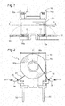
- a coil unit As shown in Figs. 1 to 3 , a coil unit, generally indicated by reference numeral 1, in which the coil terminals according to the first embodiment of the invention are incorporated, has a spool 10 made of a cylindrical portion 10b and a pair of flanges 10a integrally mounted on opposite ends of the cylindrical portion 10b, and a coil 20 formed by winding a wire 20a around the cylindrical portion 10b of the spool 10.
- the coil unit 1 further has a pair of coil terminals 30 mounted on opposite sides of one flange 10a.
- the spool 10 has a through-hole 11 formed at substantially a center thereof and inside the cylindrical portion 10b.
- One of the flanges 10a of the spool 10 has a pair of grooves 13 in each of which a coil terminal 30 is press-fitted.
- the opposite ends 21 of the wire 20a of the coil 20, wound around the spool 10, are extended out of the coil 20 and tangled and wound around respective coil terminals 30.
- the extended ends 21 of the wire 20a are omitted from Figs. 1 and 3 .
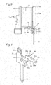
- the coil terminal 30 has a primary section 31, a terminal section 32, and a winding section 33 formed integrally therewith.
- the primary section 31 is L-shaped and has a press-fitting projection 34 for preventing the coil terminal 30 press-fitted in the groove 13 of the spool 10 from dropping therefrom.
- the terminal section 32 which has a rectangular cross-section and is extended downward and linearly from the primary section 31, is press-fitted in the terminal groove not shown defined in the electromagnetic relay at the assembling of the coil unit into the electromagnetic relay.
- the winding section 33 which has a rectangular cross-section and is extended laterally from the primary section 31, has a double-angled, proximal section 33a made of a pair of vertically shifted horizontal portions and a vertical portion connecting between the horizontal portions, and a straight portion 33b extending from the proximal section 33a.
- the proximal section 33a has a thinned portion 37, provided adjacent the primary section 31, where it is bent relative to the primary portion as shown in Fig. 1 .
- the straight portion 33b has upper and lower projections 35 and 36 defined on opposite sides with respect to the longitudinal axis of the winding section 33, i.e., integrally on the upper and lower surfaces thereof, respectively.
- the upper and lower projections 35 and 36 are laterally shifted from each other so that they constitute a pair of spaced wire engagement portions.
- the coil terminals 30 are each press-fitted in the grooves 13 of the spool 10 so that they oppose to each other. Then, the ends of the wire 20a extended from the coil 20 are wound and tangled around the winding sections of the coil terminals 30.
- each extended end 21 of the wire 20a is wound and tangled around a region of the proximal section 33a, positioned on the proximal side of the upper projection 35.
- the wire end 21 is extended distally along the side surface of the winding section 33 from the proximal end engaging surface 35a of the upper projection 35 to the distal end engaging surface 36a of the lower projection 36 and then wound and tangled around a distal region of the winding section 33, positioned adjacent and on the distal side of the lower projection 36.
- the portion of the wire 20a wound around the distal region of the winding section 33 is soldered to the coil terminal 30.
- the soldering 40 covers a region ranging from the distal end engaging surface 36a of the lower projection 36 to the distal tip end of the winding section 33.
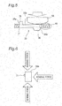
- the winding section 33 is bent by a bending jig 50 from a position illustrated in solid lines to a position illustrated in dashed lines (illustrated in solid lines in Fig. 3 ).
- the wire end 21 is extended from the proximal end engaging surface 35a of the upper projection 35 to the distal end engaging surface 36a of the lower projection 36, without being wound therearound. This prevents the wire portion extending between the projections 35 and 36 from being forced by the jig 50 and, as a result, from breaking during the bending of the winding section 33.
- soldering covers the portion of the wire 20a wound around the region ranging from the distal end engaging surface 36a of the lower projection 36 to the distal end of the winding section 33, which allows the jig to force and bend the winding section 33 without making any contact with the wire.
- a breaking of the wire 20a is reliably prevented because the jig 50 forces the winding section 33 without making any contact with the wire 20a.
- the paired wire engagement portions are constituted by the upper and lower projections 35 and 36 in the first embodiment, they may be formed in different manner.
- the wire engagement portions are provided by forming a concave portion 105 and a convex projection 106 on the opposite, respective surfaces of the straight portion 103.
- the wire engagement portions are provided by forming a convex portion 115 and a concave portion 116 on the opposite respective surfaces of the straight portion 113.
- the wire engagement portions are provided by forming convex portions 125 and 126 on the opposite respective surfaces of the straight portion 123.
- the engagement portions may be convex portions or concave portions, or they may be convex and concave portions.
- the engagement portions i.e., the projections 35 and 36
- the engagement portions are formed on opposite sides of the longitudinal axis of the winding section 33, i.e, upper and lower surfaces of the winding section 33, they may be provided in different manner.
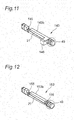
- the engagement portions are provided by forming projections 135 and 136 on the neighborhood surfaces of the straight portion 133b of the winding section 133 so that they extend in respective, orthogonal directions relative to each other.
- the wire engagement portions are provided by forming a concave portion 145 and a convex portion 146 on the neighboring respective surfaces of the straight portion 143b of the winding section 143.
- the wire engagement portions are provided by forming concave portions 155 and 156 on the neighboring respective surfaces of the straight portion 153b of the winding section 153.
- the engagement portions may be provided on the angularly shifted positions around the longitudinal axis of the winding section.
- the engagement portions are provided by forming projections 165 and 166, on the straight portion 163b of the winding section 163, each having substantially triangle cross sections aligned on the longitudinal axis of winding section 153.
- the engagement portions are provided by forming substantially triangle cross-section projections 175 and 176 so that they are oriented in different, orthogonal directions.
- the paired engagement portions may take any configuration and position provided that the wire ends 21 can be engaged thereon and extended therebetween.
- the distance between the paired engagement portions can be determined in accordance with the design requirements of the electromagnetic relay including the coil terminals provided that a space is secured for the winding portion to be forced without making any contact between the bending jig and the wire.
- the present invention may be applied to any coil terminal with a winding section and a pair of wire engagement portions formed thereon. Also, the coil terminal may be modified or redesigned in accordance with the design requirements of the electromagnetic relay including the coil terminal.
- the coil terminals described in the first to ninth embodiments are not limited to a terminal for making an electrical connection with another element such as a relay terminal for making an electrical connection with a component provided in the same device.
- Each of the structural components of the coil terminals in the first to ninth embodiment may be replaced with another, similar component in a different embodiment or may be added to a different embodiment.
- Each of the coil terminals in the first to ninth embodiments may be incorporated in any electromagnetic relay.
- the coil terminal according to the invention may be incorporated not only in the above-described coil unit but also in another coil unit. Also, the coil terminal according to the invention may be incorporated in any electromagnetic relay.
Landscapes
- Engineering & Computer Science (AREA)
- Manufacturing & Machinery (AREA)
- Physics & Mathematics (AREA)
- Electromagnetism (AREA)
- Power Engineering (AREA)
- Coils Of Transformers For General Uses (AREA)
- Electromagnets (AREA)
Abstract
Description
- The invention relates to a coil terminal and an electromagnetic relay including the coil terminal.
- Conventionally, there has been disclosed an electromagnetic relay in, for example,
JP 2000-260284(A coil terminals 12 and 13 around which opposite ends of the coil are wound or tangled. - In this electromagnetic relay, the tangled ends of the coil 2c are soldered to respective
wire connecting portions 32a and 33a of theterminals 12 and 13 which are then bent upward by typically forcing the solder portions using a dedicated jig or tool, without damaging extended portions of the wire. - With the recent trend of miniaturization of the electromagnetic relay devices, it becomes difficult for the bending tool to force only small soldered portions of the terminals and there is an increased likelihood that the bending jig will force and damage and, as a result, break the extended portions of the wire at the bending of the
coil terminals 12 and 13. - Accordingly, the present invention is to provide a coil terminal which prevents the breaking likelihood of the extended portions of the wire at the bending of the coil terminals by the bending jig and to provide an electromagnetic relay incorporating the coil terminals.
- A coil terminal according to one aspect of the invention comprises
a winding section around which is configured so that an end of coiled wire is wound around the winding section and then the winding section is bent relative to a remaining section of the coil terminal;
the winding section having a pair of, proximal and distal wire engagement portions spaced away from each other in a longitudinal direction of the winding section,
the wire end being extended in a region ranging from the proximal wire engagement portion to the distal wire engagement portions without being wound around the region. - With this arrangement of the coil terminal, at the winding of the wire end around the winding section, it is extended between the proximal and distal wire engagement portions without being wound around the region ranging between the proximal and distal wire engagement portions. This allows that the bending jig to force and bend the region without making contact with the extended wire in the region, which prevents the wire from being damaged or broken in the region.
- In another aspect of the invention, a part of the wire end is wound around a distal end region positioned on and then soldered to a distal side of the distal wire engagement portion.
- According to this aspect of the invention, the wire wound around the distal end region is covered by the solder, preventing the bending jig from making contact with the wire wound around the region, which in turn prevents the wire in that region from being damaged or broken by the bending jig even for a small coil terminal.
- In another aspect of the invention, each of the proximal and distal wire engagement portions may be a convex configuration.
- According to this aspect of the invention, a greater freedom is provided for the designing of the coil terminal.
- In another aspect of the invention, one of the proximal and distal wire engagement portions may be a convex configuration and the other of the proximal and distal wire engagement portions may be a concave configuration.
- According to those aspects of the invention, a greater freedom is provided for the designing of the coil terminal.
- In another aspect of the invention, each of the proximal and distal wire engagement portions may be a concave configuration.
- According to this aspect of the invention, a greater freedom is provided for the designing of the coil terminal.
- In another aspect of the invention, the proximal and distal wire engagement portions are angularly offset from each other about a longitudinal axis of the winding section.
- According to this aspect of the invention, a greater freedom is provided for the designing of the coil terminal.
- In another aspect of the invention, the proximal and distal wire engagement portions are positioned on opposite sides of a longitudinal axis of the winding section.
- According to this aspect of the invention, a greater freedom is provided for the designing of the coil terminal.
- In another aspect of the invention, an electromagnetic relay comprises any one of the coil terminals.
- According to this aspect of the invention, the electromagnetic relay is provided which is capable of preventing the wire from being damaged or broken at the bending of the winding section by means of the bending jig or tool.
-
-
Fig. 1 is a top plan view of a coil unit in which coil terminals of the first embodiment of the invention are assembled, showing the coil terminals before they are bent; -
Fig. 2 is a cross sectional view of the coil unit taken along lines II-II inFig. 1 ; -
Fig. 3 is a side elevational view of the coil unit, showing coil terminals before they are bent; -
Fig. 4 is a perspective view showing the coil terminal assembled in the electromagnetic relay inFig. 1 ; -
Fig. 5 is a schematic view showing that the coil terminal is being forced and bent by a bending jig or tool; -
Fig. 6 is a schematic view showing forces applied to the coil terminal; -
Fig. 7 is a schematic view showing a coil terminal according to the second embodiment of the invention; -
Fig. 8 is a schematic view showing a coil terminal according to the third embodiment of the invention; -
Fig. 9 is a schematic view showing a coil terminal according to the fourth embodiment of the invention; -
Fig. 10 is a schematic view showing a coil terminal according to the fifth embodiment of the invention; -
Fig. 11 is a schematic view showing a coil terminal according to the sixth embodiment of the invention; -
Fig. 12 is a schematic view showing a coil terminal according to the seventh embodiment of the invention; -
Fig. 13 is a schematic view showing a coil terminal according to the eighth embodiment of the invention; and -
Fig. 14 is a schematic view showing a coil terminal according to the ninth embodiment of the invention. - With reference to the accompanying drawings, a coil unit incorporating a coil terminal according to an embodiment of the invention will be described below.
- In the following descriptions, directional terminology such as "upper", "lower", etc., is used with reference to the orientation of the drawing(s) being described, it is used for purposes of better understanding of the invention and is in no way limiting the technical scope of the invention.
- As shown in
Figs. 1 to 3 , a coil unit, generally indicated byreference numeral 1, in which the coil terminals according to the first embodiment of the invention are incorporated, has aspool 10 made of acylindrical portion 10b and a pair offlanges 10a integrally mounted on opposite ends of thecylindrical portion 10b, and acoil 20 formed by winding awire 20a around thecylindrical portion 10b of thespool 10. Thecoil unit 1 further has a pair ofcoil terminals 30 mounted on opposite sides of oneflange 10a. - As shown in
Fig. 2 , thespool 10 has a through-hole 11 formed at substantially a center thereof and inside thecylindrical portion 10b. One of theflanges 10a of thespool 10 has a pair ofgrooves 13 in each of which acoil terminal 30 is press-fitted. - The
opposite ends 21 of thewire 20a of thecoil 20, wound around thespool 10, are extended out of thecoil 20 and tangled and wound aroundrespective coil terminals 30. For convenience, theextended ends 21 of thewire 20a are omitted fromFigs. 1 and3 . - As shown in
Fig. 4 , thecoil terminal 30 has aprimary section 31, aterminal section 32, and awinding section 33 formed integrally therewith. - The
primary section 31 is L-shaped and has a press-fitting projection 34 for preventing thecoil terminal 30 press-fitted in thegroove 13 of thespool 10 from dropping therefrom. - The
terminal section 32, which has a rectangular cross-section and is extended downward and linearly from theprimary section 31, is press-fitted in the terminal groove not shown defined in the electromagnetic relay at the assembling of the coil unit into the electromagnetic relay. - The
winding section 33, which has a rectangular cross-section and is extended laterally from theprimary section 31, has a double-angled,proximal section 33a made of a pair of vertically shifted horizontal portions and a vertical portion connecting between the horizontal portions, and astraight portion 33b extending from theproximal section 33a. Theproximal section 33a has athinned portion 37, provided adjacent theprimary section 31, where it is bent relative to the primary portion as shown inFig. 1 . Also, thestraight portion 33b has upper andlower projections winding section 33, i.e., integrally on the upper and lower surfaces thereof, respectively. The upper andlower projections - Next, discussions will be made to an assembling of the coil unit.
- The
coil terminals 30 are each press-fitted in thegrooves 13 of thespool 10 so that they oppose to each other. Then, the ends of thewire 20a extended from thecoil 20 are wound and tangled around the winding sections of thecoil terminals 30. - In this process, as shown in
Fig. 5 , each extendedend 21 of thewire 20a is wound and tangled around a region of theproximal section 33a, positioned on the proximal side of theupper projection 35. Next, thewire end 21 is extended distally along the side surface of thewinding section 33 from the proximal endengaging surface 35a of theupper projection 35 to the distal endengaging surface 36a of thelower projection 36 and then wound and tangled around a distal region of thewinding section 33, positioned adjacent and on the distal side of thelower projection 36. - Subsequently, the portion of the
wire 20a wound around the distal region of the windingsection 33 is soldered to thecoil terminal 30. For example, thesoldering 40 covers a region ranging from the distalend engaging surface 36a of thelower projection 36 to the distal tip end of the windingsection 33. - Next, as shown in
Fig. 1 , the windingsection 33 is bent by a bendingjig 50 from a position illustrated in solid lines to a position illustrated in dashed lines (illustrated in solid lines inFig. 3 ). - Specifically, as shown in
Fig. 5 , in this bending the windingsection 33 is forced by thejig 50 at the region between the upper andlower projections solder 40. - As such, in the process of winding the
wire end 21 around the windingsection 33, thewire end 21 is extended from the proximalend engaging surface 35a of theupper projection 35 to the distalend engaging surface 36a of thelower projection 36, without being wound therearound. This prevents the wire portion extending between theprojections jig 50 and, as a result, from breaking during the bending of the windingsection 33. - Also, the soldering covers the portion of the
wire 20a wound around the region ranging from the distalend engaging surface 36a of thelower projection 36 to the distal end of the windingsection 33, which allows the jig to force and bend the windingsection 33 without making any contact with the wire. - As described above, according to the embodiment a breaking of the
wire 20a is reliably prevented because thejig 50 forces the windingsection 33 without making any contact with thewire 20a. - Although the paired wire engagement portions are constituted by the upper and
lower projections Fig. 7 the wire engagement portions are provided by forming aconcave portion 105 and aconvex projection 106 on the opposite, respective surfaces of thestraight portion 103. Alternately, in the third embodiment shown inFig. 8 the wire engagement portions are provided by forming aconvex portion 115 and aconcave portion 116 on the opposite respective surfaces of thestraight portion 113. Alternatively, in the fourth embodiment shown inFig. 9 the wire engagement portions are provided by formingconvex portions straight portion 123. As described above, the engagement portions may be convex portions or concave portions, or they may be convex and concave portions. - Although in the first embodiment the engagement portions, i.e., the
projections section 33, i.e, upper and lower surfaces of the windingsection 33, they may be provided in different manner. For example, in the fifth embodiment shown in inFig. 10 the engagement portions are provided by formingprojections straight portion 133b of the windingsection 133 so that they extend in respective, orthogonal directions relative to each other. Alternatively, in the sixth embodiment shown inFig. 11 the wire engagement portions are provided by forming aconcave portion 145 and aconvex portion 146 on the neighboring respective surfaces of thestraight portion 143b of the windingsection 143. Alternatively, in the seventh embodiment shown inFig. 12 the wire engagement portions are provided by formingconcave portions straight portion 153b of the windingsection 153. As described above, the engagement portions may be provided on the angularly shifted positions around the longitudinal axis of the winding section. - Also, in the eighth embodiment shown in
Fig. 13 the engagement portions are provided by formingprojections straight portion 163b of the windingsection 163, each having substantially triangle cross sections aligned on the longitudinal axis of windingsection 153. Alternatively, in the ninth embodiment shown inFig. 14 the engagement portions are provided by forming substantiallytriangle cross-section projections - As described above, the paired engagement portions may take any configuration and position provided that the wire ends 21 can be engaged thereon and extended therebetween.
- The distance between the paired engagement portions can be determined in accordance with the design requirements of the electromagnetic relay including the coil terminals provided that a space is secured for the winding portion to be forced without making any contact between the bending jig and the wire.
- The present invention may be applied to any coil terminal with a winding section and a pair of wire engagement portions formed thereon. Also, the coil terminal may be modified or redesigned in accordance with the design requirements of the electromagnetic relay including the coil terminal.
- The coil terminals described in the first to ninth embodiments are not limited to a terminal for making an electrical connection with another element such as a relay terminal for making an electrical connection with a component provided in the same device.
- Each of the structural components of the coil terminals in the first to ninth embodiment may be replaced with another, similar component in a different embodiment or may be added to a different embodiment.
- Each of the coil terminals in the first to ninth embodiments may be incorporated in any electromagnetic relay.
- The coil terminal according to the invention may be incorporated not only in the above-described coil unit but also in another coil unit. Also, the coil terminal according to the invention may be incorporated in any electromagnetic relay.
-
- 10: spool
- 10a: flange
- 11: through-hole
- 20: coil
- 21: wire end
- 30: coil terminal
- 32: terminal section
- 33, 103, 113, 123, 133, 143, 153, 163, 173: winding section
- 33a: proximal section
- 33b, 103b, 113b, 123b, 133b, 143b, 153b, 163b, 173b: straight portion
- 34: press-fitting projection
- 35, 115, 135, 136, 146, 165, 166, 175, 176: projection
- 35a: end surface
- 36, 106: projection
- 36a: end surface
- 37: thinned portion
- 40: solder
- 50: jig
- 105, 116, 125, 126, 145, 155, 156: concave portion
Claims (8)
- A coil terminal, comprising:a winding section which is configured so that an end of coiled wire is wound around the winding section and then the winding section is bent relative to a remaining section of the coil terminal;the winding section having a pair of, proximal and distal wire engagement portions spaced away from each other in a longitudinal direction of the winding section,the wire end being extended in a region ranging from the proximal wire engagement portion to the distal wire engagement portions without being wound around the region.
- The coil terminal of claim 1, wherein a part of the wire end is wound around and then soldered to a distal region of the distal wire engagement portion.
- The coil terminal of claim 1 or 2, wherein each of the proximal and distal wire engagement portions is a convex configuration.
- The coil terminal of claim 1 or 2, wherein one of the proximal and distal wire engagement portions is a convex configuration and the other of the proximal and distal wire engagement portions is a concave configuration.
- The coil terminal of claim 1 or 2, wherein each of the proximal and distal wire engagement portions is a concave configuration.
- The coil terminal in any of claims 1-5, wherein the proximal and distal wire engagement portions are angularly offset from each other about a longitudinal axis of the winding section.
- The coil terminal in any of claims 1-5, wherein the proximal and distal wire engagement portions are positioned on opposite sides of a longitudinal axis of the winding section.
- An electromagnetic relay comprising a coil terminal claimed in any of claims 1-7.
Applications Claiming Priority (1)
| Application Number | Priority Date | Filing Date | Title |
|---|---|---|---|
| JP2014052381A JP2015176757A (en) | 2014-03-14 | 2014-03-14 | Coil terminal and electromagnetic relay |
Publications (2)
| Publication Number | Publication Date |
|---|---|
| EP2919251A1 true EP2919251A1 (en) | 2015-09-16 |
| EP2919251B1 EP2919251B1 (en) | 2017-04-12 |
Family
ID=52232032
Family Applications (1)
| Application Number | Title | Priority Date | Filing Date |
|---|---|---|---|
| EP14200535.4A Not-in-force EP2919251B1 (en) | 2014-03-14 | 2014-12-30 | Coil terminal and electromagnetic relay |
Country Status (4)
| Country | Link |
|---|---|
| US (1) | US9401238B2 (en) |
| EP (1) | EP2919251B1 (en) |
| JP (1) | JP2015176757A (en) |
| CN (1) | CN104916497A (en) |
Families Citing this family (6)
| Publication number | Priority date | Publication date | Assignee | Title |
|---|---|---|---|---|
| JP6344282B2 (en) * | 2015-03-26 | 2018-06-20 | オムロン株式会社 | Coil terminal and electromagnetic relay having the same |
| JP6332480B1 (en) * | 2017-01-11 | 2018-05-30 | 富士電機機器制御株式会社 | Magnetic contactor |
| JP7120275B2 (en) * | 2020-07-07 | 2022-08-17 | 株式会社デンソーエレクトロニクス | electromagnetic relay |
| CN112786371A (en) * | 2021-02-07 | 2021-05-11 | 三友联众集团股份有限公司 | Coil terminal improved electromagnetic relay |
| JP7484787B2 (en) | 2021-03-29 | 2024-05-16 | 株式会社デンソーエレクトロニクス | Electromagnetic Relay |
| JP2025040302A (en) * | 2023-09-11 | 2025-03-24 | オムロン株式会社 | Electromagnetic Relay |
Citations (4)
| Publication number | Priority date | Publication date | Assignee | Title |
|---|---|---|---|---|
| JPS5571005A (en) * | 1978-11-22 | 1980-05-28 | Omron Tateisi Electronics Co | Connecting method of coil |
| JPH0554948A (en) * | 1991-08-27 | 1993-03-05 | Matsushita Electric Works Ltd | Electric cable connection terminal treating method |
| JP2000260284A (en) | 1999-03-08 | 2000-09-22 | Omron Corp | Electromagnetic relay and assembly method thereof |
| WO2014038499A1 (en) * | 2012-09-05 | 2014-03-13 | Idec株式会社 | Electromagnet device, and electromagnetic relay |
Family Cites Families (9)
| Publication number | Priority date | Publication date | Assignee | Title |
|---|---|---|---|---|
| US1805638A (en) * | 1929-10-30 | 1931-05-19 | Sparks Withington Co | Radio coupling coil |
| US4166265A (en) * | 1978-02-03 | 1979-08-28 | Amp Incorporated | Coil bobbins and termination of coil windings |
| US4258973A (en) * | 1979-06-07 | 1981-03-31 | Amp Incorporated | Connecting means having kinematic conductor-contacting portions |
| IT220750Z2 (en) * | 1990-12-11 | 1993-11-08 | Veglia Borletti Srl | ELECTRIC COIL AND RELATED METHOD OF MANUFACTURE |
| JPH07335291A (en) * | 1994-06-03 | 1995-12-22 | Sumitomo Electric Ind Ltd | Rotation sensor wire binding terminal |
| JP3651651B2 (en) * | 1998-04-19 | 2005-05-25 | オムロン株式会社 | Electric wire welding terminal and welding torch suitable for electric wire welding to the terminal |
| WO2000054296A1 (en) | 1999-03-05 | 2000-09-14 | Omron Corporation | Electromagnetic relay |
| JP2006156917A (en) * | 2003-12-24 | 2006-06-15 | Denso Corp | Ignition coil and method of joining secondary coil assembly |
| CN101079345B (en) * | 2006-05-26 | 2011-02-16 | 浙江三花制冷集团有限公司 | Coil framework and electromagnetic coil |
-
2014
- 2014-03-14 JP JP2014052381A patent/JP2015176757A/en active Pending
- 2014-12-15 CN CN201410779457.7A patent/CN104916497A/en active Pending
- 2014-12-30 EP EP14200535.4A patent/EP2919251B1/en not_active Not-in-force
-
2015
- 2015-01-05 US US14/589,549 patent/US9401238B2/en not_active Expired - Fee Related
Patent Citations (4)
| Publication number | Priority date | Publication date | Assignee | Title |
|---|---|---|---|---|
| JPS5571005A (en) * | 1978-11-22 | 1980-05-28 | Omron Tateisi Electronics Co | Connecting method of coil |
| JPH0554948A (en) * | 1991-08-27 | 1993-03-05 | Matsushita Electric Works Ltd | Electric cable connection terminal treating method |
| JP2000260284A (en) | 1999-03-08 | 2000-09-22 | Omron Corp | Electromagnetic relay and assembly method thereof |
| WO2014038499A1 (en) * | 2012-09-05 | 2014-03-13 | Idec株式会社 | Electromagnet device, and electromagnetic relay |
Also Published As
| Publication number | Publication date |
|---|---|
| CN104916497A (en) | 2015-09-16 |
| US20150262743A1 (en) | 2015-09-17 |
| EP2919251B1 (en) | 2017-04-12 |
| JP2015176757A (en) | 2015-10-05 |
| US9401238B2 (en) | 2016-07-26 |
Similar Documents
| Publication | Publication Date | Title |
|---|---|---|
| KR101849493B1 (en) | Pressure contact type connector and manufacturing method of the same | |
| US9401238B2 (en) | Coil terminal and electromagnetic relay | |
| JP6413096B2 (en) | Coil parts | |
| JP6445396B2 (en) | Common mode filter | |
| JP5020155B2 (en) | contact | |
| JP6631591B2 (en) | Press-fit terminal and method of manufacturing the same | |
| JP6278024B2 (en) | connector | |
| JP2014110214A (en) | Female terminal | |
| JP2014132630A (en) | Coil component | |
| US20160120024A1 (en) | Linear Conductor Connection Terminal | |
| JP2012074376A (en) | Level bridge | |
| US9673548B2 (en) | Contact connection structure | |
| JP2016058471A (en) | Wound coil and method of manufacturing the same | |
| KR102137880B1 (en) | Terminal | |
| TWI616032B (en) | Crimp connector | |
| JP2015055587A (en) | Resolver stator harness structure | |
| JP2015185243A (en) | Tuning-fork terminal | |
| JP5093893B2 (en) | choke coil | |
| JP2011070949A (en) | Wire connection structure | |
| JP5169649B2 (en) | Inductance component manufacturing method | |
| JP2015103484A (en) | Connection terminal for insertion and manufacturing method thereof | |
| KR200480015Y1 (en) | Multi joint terminal | |
| JP5058745B2 (en) | Coil device | |
| CN109216949B (en) | electrical connector | |
| JP2013122941A (en) | Pin terminal of lead wire and method of fixing lead wire |
Legal Events
| Date | Code | Title | Description |
|---|---|---|---|
| PUAI | Public reference made under article 153(3) epc to a published international application that has entered the european phase |
Free format text: ORIGINAL CODE: 0009012 |
|
| 17P | Request for examination filed |
Effective date: 20150130 |
|
| AK | Designated contracting states |
Kind code of ref document: A1 Designated state(s): AL AT BE BG CH CY CZ DE DK EE ES FI FR GB GR HR HU IE IS IT LI LT LU LV MC MK MT NL NO PL PT RO RS SE SI SK SM TR |
|
| AX | Request for extension of the european patent |
Extension state: BA ME |
|
| RIN1 | Information on inventor provided before grant (corrected) |
Inventor name: TSURUSAKI, AKIRA Inventor name: WADA, SHINTARO Inventor name: YAMAUCHI, HIDETO Inventor name: MIMURA, YOSHIAKI Inventor name: SANADA, HIRONORI |
|
| GRAP | Despatch of communication of intention to grant a patent |
Free format text: ORIGINAL CODE: EPIDOSNIGR1 |
|
| STAA | Information on the status of an ep patent application or granted ep patent |
Free format text: STATUS: GRANT OF PATENT IS INTENDED |
|
| RIC1 | Information provided on ipc code assigned before grant |
Ipc: H01H 49/00 20060101AFI20161125BHEP Ipc: H01H 50/44 20060101ALI20161125BHEP |
|
| INTG | Intention to grant announced |
Effective date: 20161213 |
|
| GRAS | Grant fee paid |
Free format text: ORIGINAL CODE: EPIDOSNIGR3 |
|
| GRAA | (expected) grant |
Free format text: ORIGINAL CODE: 0009210 |
|
| STAA | Information on the status of an ep patent application or granted ep patent |
Free format text: STATUS: THE PATENT HAS BEEN GRANTED |
|
| AK | Designated contracting states |
Kind code of ref document: B1 Designated state(s): AL AT BE BG CH CY CZ DE DK EE ES FI FR GB GR HR HU IE IS IT LI LT LU LV MC MK MT NL NO PL PT RO RS SE SI SK SM TR |
|
| REG | Reference to a national code |
Ref country code: GB Ref legal event code: FG4D |
|
| REG | Reference to a national code |
Ref country code: CH Ref legal event code: EP |
|
| REG | Reference to a national code |
Ref country code: IE Ref legal event code: FG4D |
|
| REG | Reference to a national code |
Ref country code: AT Ref legal event code: REF Ref document number: 884650 Country of ref document: AT Kind code of ref document: T Effective date: 20170515 |
|
| REG | Reference to a national code |
Ref country code: DE Ref legal event code: R096 Ref document number: 602014008499 Country of ref document: DE |
|
| REG | Reference to a national code |
Ref country code: NL Ref legal event code: MP Effective date: 20170412 |
|
| REG | Reference to a national code |
Ref country code: LT Ref legal event code: MG4D |
|
| REG | Reference to a national code |
Ref country code: AT Ref legal event code: MK05 Ref document number: 884650 Country of ref document: AT Kind code of ref document: T Effective date: 20170412 |
|
| PG25 | Lapsed in a contracting state [announced via postgrant information from national office to epo] |
Ref country code: NL Free format text: LAPSE BECAUSE OF FAILURE TO SUBMIT A TRANSLATION OF THE DESCRIPTION OR TO PAY THE FEE WITHIN THE PRESCRIBED TIME-LIMIT Effective date: 20170412 |
|
| PG25 | Lapsed in a contracting state [announced via postgrant information from national office to epo] |
Ref country code: ES Free format text: LAPSE BECAUSE OF FAILURE TO SUBMIT A TRANSLATION OF THE DESCRIPTION OR TO PAY THE FEE WITHIN THE PRESCRIBED TIME-LIMIT Effective date: 20170412 Ref country code: HR Free format text: LAPSE BECAUSE OF FAILURE TO SUBMIT A TRANSLATION OF THE DESCRIPTION OR TO PAY THE FEE WITHIN THE PRESCRIBED TIME-LIMIT Effective date: 20170412 Ref country code: NO Free format text: LAPSE BECAUSE OF FAILURE TO SUBMIT A TRANSLATION OF THE DESCRIPTION OR TO PAY THE FEE WITHIN THE PRESCRIBED TIME-LIMIT Effective date: 20170712 Ref country code: AT Free format text: LAPSE BECAUSE OF FAILURE TO SUBMIT A TRANSLATION OF THE DESCRIPTION OR TO PAY THE FEE WITHIN THE PRESCRIBED TIME-LIMIT Effective date: 20170412 Ref country code: GR Free format text: LAPSE BECAUSE OF FAILURE TO SUBMIT A TRANSLATION OF THE DESCRIPTION OR TO PAY THE FEE WITHIN THE PRESCRIBED TIME-LIMIT Effective date: 20170713 Ref country code: LT Free format text: LAPSE BECAUSE OF FAILURE TO SUBMIT A TRANSLATION OF THE DESCRIPTION OR TO PAY THE FEE WITHIN THE PRESCRIBED TIME-LIMIT Effective date: 20170412 Ref country code: FI Free format text: LAPSE BECAUSE OF FAILURE TO SUBMIT A TRANSLATION OF THE DESCRIPTION OR TO PAY THE FEE WITHIN THE PRESCRIBED TIME-LIMIT Effective date: 20170412 |
|
| PG25 | Lapsed in a contracting state [announced via postgrant information from national office to epo] |
Ref country code: RS Free format text: LAPSE BECAUSE OF FAILURE TO SUBMIT A TRANSLATION OF THE DESCRIPTION OR TO PAY THE FEE WITHIN THE PRESCRIBED TIME-LIMIT Effective date: 20170412 Ref country code: PL Free format text: LAPSE BECAUSE OF FAILURE TO SUBMIT A TRANSLATION OF THE DESCRIPTION OR TO PAY THE FEE WITHIN THE PRESCRIBED TIME-LIMIT Effective date: 20170412 Ref country code: BG Free format text: LAPSE BECAUSE OF FAILURE TO SUBMIT A TRANSLATION OF THE DESCRIPTION OR TO PAY THE FEE WITHIN THE PRESCRIBED TIME-LIMIT Effective date: 20170712 Ref country code: LV Free format text: LAPSE BECAUSE OF FAILURE TO SUBMIT A TRANSLATION OF THE DESCRIPTION OR TO PAY THE FEE WITHIN THE PRESCRIBED TIME-LIMIT Effective date: 20170412 Ref country code: IS Free format text: LAPSE BECAUSE OF FAILURE TO SUBMIT A TRANSLATION OF THE DESCRIPTION OR TO PAY THE FEE WITHIN THE PRESCRIBED TIME-LIMIT Effective date: 20170812 Ref country code: SE Free format text: LAPSE BECAUSE OF FAILURE TO SUBMIT A TRANSLATION OF THE DESCRIPTION OR TO PAY THE FEE WITHIN THE PRESCRIBED TIME-LIMIT Effective date: 20170412 |
|
| REG | Reference to a national code |
Ref country code: DE Ref legal event code: R097 Ref document number: 602014008499 Country of ref document: DE |
|
| PG25 | Lapsed in a contracting state [announced via postgrant information from national office to epo] |
Ref country code: CZ Free format text: LAPSE BECAUSE OF FAILURE TO SUBMIT A TRANSLATION OF THE DESCRIPTION OR TO PAY THE FEE WITHIN THE PRESCRIBED TIME-LIMIT Effective date: 20170412 Ref country code: DK Free format text: LAPSE BECAUSE OF FAILURE TO SUBMIT A TRANSLATION OF THE DESCRIPTION OR TO PAY THE FEE WITHIN THE PRESCRIBED TIME-LIMIT Effective date: 20170412 Ref country code: SK Free format text: LAPSE BECAUSE OF FAILURE TO SUBMIT A TRANSLATION OF THE DESCRIPTION OR TO PAY THE FEE WITHIN THE PRESCRIBED TIME-LIMIT Effective date: 20170412 Ref country code: EE Free format text: LAPSE BECAUSE OF FAILURE TO SUBMIT A TRANSLATION OF THE DESCRIPTION OR TO PAY THE FEE WITHIN THE PRESCRIBED TIME-LIMIT Effective date: 20170412 Ref country code: RO Free format text: LAPSE BECAUSE OF FAILURE TO SUBMIT A TRANSLATION OF THE DESCRIPTION OR TO PAY THE FEE WITHIN THE PRESCRIBED TIME-LIMIT Effective date: 20170412 |
|
| PLBE | No opposition filed within time limit |
Free format text: ORIGINAL CODE: 0009261 |
|
| STAA | Information on the status of an ep patent application or granted ep patent |
Free format text: STATUS: NO OPPOSITION FILED WITHIN TIME LIMIT |
|
| PG25 | Lapsed in a contracting state [announced via postgrant information from national office to epo] |
Ref country code: SM Free format text: LAPSE BECAUSE OF FAILURE TO SUBMIT A TRANSLATION OF THE DESCRIPTION OR TO PAY THE FEE WITHIN THE PRESCRIBED TIME-LIMIT Effective date: 20170412 Ref country code: IT Free format text: LAPSE BECAUSE OF FAILURE TO SUBMIT A TRANSLATION OF THE DESCRIPTION OR TO PAY THE FEE WITHIN THE PRESCRIBED TIME-LIMIT Effective date: 20170412 |
|
| 26N | No opposition filed |
Effective date: 20180115 |
|
| PG25 | Lapsed in a contracting state [announced via postgrant information from national office to epo] |
Ref country code: SI Free format text: LAPSE BECAUSE OF FAILURE TO SUBMIT A TRANSLATION OF THE DESCRIPTION OR TO PAY THE FEE WITHIN THE PRESCRIBED TIME-LIMIT Effective date: 20170412 |
|
| REG | Reference to a national code |
Ref country code: DE Ref legal event code: R119 Ref document number: 602014008499 Country of ref document: DE |
|
| REG | Reference to a national code |
Ref country code: CH Ref legal event code: PL |
|
| PG25 | Lapsed in a contracting state [announced via postgrant information from national office to epo] |
Ref country code: MT Free format text: LAPSE BECAUSE OF NON-PAYMENT OF DUE FEES Effective date: 20171230 Ref country code: LU Free format text: LAPSE BECAUSE OF NON-PAYMENT OF DUE FEES Effective date: 20171230 |
|
| REG | Reference to a national code |
Ref country code: FR Ref legal event code: ST Effective date: 20180831 |
|
| REG | Reference to a national code |
Ref country code: IE Ref legal event code: MM4A |
|
| REG | Reference to a national code |
Ref country code: BE Ref legal event code: MM Effective date: 20171231 |
|
| PG25 | Lapsed in a contracting state [announced via postgrant information from national office to epo] |
Ref country code: DE Free format text: LAPSE BECAUSE OF NON-PAYMENT OF DUE FEES Effective date: 20180703 Ref country code: FR Free format text: LAPSE BECAUSE OF NON-PAYMENT OF DUE FEES Effective date: 20180102 Ref country code: IE Free format text: LAPSE BECAUSE OF NON-PAYMENT OF DUE FEES Effective date: 20171230 |
|
| PG25 | Lapsed in a contracting state [announced via postgrant information from national office to epo] |
Ref country code: BE Free format text: LAPSE BECAUSE OF NON-PAYMENT OF DUE FEES Effective date: 20171231 Ref country code: CH Free format text: LAPSE BECAUSE OF NON-PAYMENT OF DUE FEES Effective date: 20171231 Ref country code: LI Free format text: LAPSE BECAUSE OF NON-PAYMENT OF DUE FEES Effective date: 20171231 |
|
| PG25 | Lapsed in a contracting state [announced via postgrant information from national office to epo] |
Ref country code: MC Free format text: LAPSE BECAUSE OF FAILURE TO SUBMIT A TRANSLATION OF THE DESCRIPTION OR TO PAY THE FEE WITHIN THE PRESCRIBED TIME-LIMIT Effective date: 20170412 Ref country code: HU Free format text: LAPSE BECAUSE OF FAILURE TO SUBMIT A TRANSLATION OF THE DESCRIPTION OR TO PAY THE FEE WITHIN THE PRESCRIBED TIME-LIMIT; INVALID AB INITIO Effective date: 20141230 |
|
| GBPC | Gb: european patent ceased through non-payment of renewal fee |
Effective date: 20181230 |
|
| PG25 | Lapsed in a contracting state [announced via postgrant information from national office to epo] |
Ref country code: CY Free format text: LAPSE BECAUSE OF FAILURE TO SUBMIT A TRANSLATION OF THE DESCRIPTION OR TO PAY THE FEE WITHIN THE PRESCRIBED TIME-LIMIT Effective date: 20170412 |
|
| PG25 | Lapsed in a contracting state [announced via postgrant information from national office to epo] |
Ref country code: MK Free format text: LAPSE BECAUSE OF FAILURE TO SUBMIT A TRANSLATION OF THE DESCRIPTION OR TO PAY THE FEE WITHIN THE PRESCRIBED TIME-LIMIT Effective date: 20170412 |
|
| PG25 | Lapsed in a contracting state [announced via postgrant information from national office to epo] |
Ref country code: GB Free format text: LAPSE BECAUSE OF NON-PAYMENT OF DUE FEES Effective date: 20181230 |
|
| PG25 | Lapsed in a contracting state [announced via postgrant information from national office to epo] |
Ref country code: TR Free format text: LAPSE BECAUSE OF FAILURE TO SUBMIT A TRANSLATION OF THE DESCRIPTION OR TO PAY THE FEE WITHIN THE PRESCRIBED TIME-LIMIT Effective date: 20170412 |
|
| PG25 | Lapsed in a contracting state [announced via postgrant information from national office to epo] |
Ref country code: PT Free format text: LAPSE BECAUSE OF FAILURE TO SUBMIT A TRANSLATION OF THE DESCRIPTION OR TO PAY THE FEE WITHIN THE PRESCRIBED TIME-LIMIT Effective date: 20170412 |
|
| PG25 | Lapsed in a contracting state [announced via postgrant information from national office to epo] |
Ref country code: AL Free format text: LAPSE BECAUSE OF FAILURE TO SUBMIT A TRANSLATION OF THE DESCRIPTION OR TO PAY THE FEE WITHIN THE PRESCRIBED TIME-LIMIT Effective date: 20170412 |