EP2919039A1 - Method for collecting, in a collecting device distinct from a central unit, data coming from a plurality of seismic acquisition units - Google Patents
Method for collecting, in a collecting device distinct from a central unit, data coming from a plurality of seismic acquisition units Download PDFInfo
- Publication number
- EP2919039A1 EP2919039A1 EP15156337.6A EP15156337A EP2919039A1 EP 2919039 A1 EP2919039 A1 EP 2919039A1 EP 15156337 A EP15156337 A EP 15156337A EP 2919039 A1 EP2919039 A1 EP 2919039A1
- Authority
- EP
- European Patent Office
- Prior art keywords
- data
- seismic
- sink unit
- unit
- sink
- Prior art date
- Legal status (The legal status is an assumption and is not a legal conclusion. Google has not performed a legal analysis and makes no representation as to the accuracy of the status listed.)
- Granted
Links
Images

Classifications
-
- G—PHYSICS
- G01—MEASURING; TESTING
- G01V—GEOPHYSICS; GRAVITATIONAL MEASUREMENTS; DETECTING MASSES OR OBJECTS; TAGS
- G01V1/00—Seismology; Seismic or acoustic prospecting or detecting
- G01V1/22—Transmitting seismic signals to recording or processing apparatus
- G01V1/223—Radioseismic systems
-
- G—PHYSICS
- G01—MEASURING; TESTING
- G01V—GEOPHYSICS; GRAVITATIONAL MEASUREMENTS; DETECTING MASSES OR OBJECTS; TAGS
- G01V1/00—Seismology; Seismic or acoustic prospecting or detecting
- G01V1/22—Transmitting seismic signals to recording or processing apparatus
Definitions
- the field of the invention is that of seismic data acquisition systems.
- the principle of operation of these systems is as follows: for a given seismic survey, one or several seismic sources (explosives, falling weights, vibrators, air guns, etc.) are activated to propagate omnidirectional seismic wave trains; the wave trains reflected by the layers of the subsurface are detected by seismic sensors, which generate a signal characterizing the reflection of the waves on the geological interfaces of the subsurface.
- seismic sources explosive, falling weights, vibrators, air guns, etc.
- the invention relates to a method for collecting, in a collecting device (e.g. a harvester equipment) distinct from a central unit, data coming from a plurality of seismic acquisition units.
- a collecting device e.g. a harvester equipment
- the invention can be applied notably to the oil prospecting industry using seismic method, but can be of interest for any other field implementing a seismic data acquisition system.
- a seismic data acquisition system comprises a network connected to a central unit.
- the central unit collects the seismic data and processes them to generate a specific file (SEGD) analysed by the seismic community.
- SEGD specific file
- the network comprises a plurality of wired acquisition lines.
- Each wired acquisition line comprises nodes (also referred to as “seismic acquisition units”) and concentrators, thus all data can be received in the central unit in a real-time manner.
- the nodes are assembled in series along a telemetry cable and are each associated with at least one seismic sensor (in general, strings of seismic sensors). These nodes process signals transmitted by the seismic sensor(s) and generate data.
- the data include seismic data and non-seismic data.
- the non-seismic data are for example QC data (for "Quality Control data”), i.e.
- the concentrators are assembled in series along the telemetry cable and are each associated with at least one of the nodes. Each concentrator receives the data generated by the node(s) with which it is associated.
- the sensors are either analog sensors or digital sensors. When analog sensors (also referred to as “geophones”) are used, they are generally interconnected by cables to form clusters referred to as "strings of geophones". One or several of these strings of geophones (in series or in parallel) are connected to each node and this latter performs an analog to digital conversion of the signal from the groups of geophones and send these data to the central unit (via the network of concentrators).
- digital sensors e.g. micro-machined accelerometers, also referred to as "MEMS-based digital accelerometer”
- MEMS-based digital accelerometer are integrated in the nodes, thus eliminating the geophone strings.
- Each node integrates one or several digital sensors.
- the network comprises wireless seismic acquisition units.
- Each wireless seismic acquisition unit also called “node” is independent and associated with (i.e. is connected to or integrates one or several functions of) one or several of aforesaid nodes and generates data (including seismic data and non-seismic data).
- the paths from the nodes to the central unit are the same for the seismic data and the non-seismic data (e.g. QC data). That means that the non-seismic data are collected by the central unit which also collects and processes the seismic data. In other words, all the information is centralized in the central unit.
- the field team shall always communicate with the lab team that manages the central unit in order to obtain information (e.g. non-seismic data, but possibly also seismic data) concerning the seismic acquisition units deployed on the field.
- a field operator (of the field team) is not able to retrieve and process the non-seismic data coming from the seismic acquisition units, without any communication with the lab team.
- the field operator is not autonomous to manage the seismic acquisition units on the field.
- a drawback is that only wireless seismic acquisition units located in the coverage area of the central unit can access the wireless point-to-multipoint network and send their data to the central unit.
- the field team has to communicate with the lab team (that manages the central unit) in order to obtain information (e.g. non-seismic data, but possibly also seismic data) concerning the wireless seismic acquisition units deployed on the field. Therefore, as for the wired implementation, the field operator is not able to retrieve and process the non-seismic data coming from the seismic acquisition units, without any communication with the lab team.
- the field team can directly collect seismic data and non-seismic data on the field.
- the wireless seismic acquisition units shall be configured (e.g. IP address or WIFI parameters or any network configuration parameters) in order to communicate with the harvester equipment; only wireless seismic acquisition units located in the coverage area of the harvester equipment can access the wireless point-to-multipoint network and send their data to the harvester equipment; the number of wireless seismic acquisition units that the harvester equipment can manage on the field is limited (e.g. one dozen); and the wireless seismic acquisition units located in harsh environment (forest, dense vegetation, etc.) are not accessible by the harvester equipment (i.e. all of them cannot be reached by the harvester equipment).
- a main drawback is that a heavy infrastructure must be deployed on tens of km 2 areas to harvest all the data in real time.
- the field team has to communicate with the lab team (that manages the central unit) in order to obtain information (e.g. non-seismic data, but possibly also seismic data) concerning the wireless seismic acquisition units deployed on the field. Therefore, as for the wired implementation, the field operator is not able to retrieve and process the non-seismic data coming from the seismic acquisition units, without any communication with the lab team.
- a particular embodiment of the invention proposes a method for collecting, in a collecting device distinct from a central unit, data coming from a plurality of seismic acquisition units.
- the method comprises a step of assigning at least one device as a sink unit.
- the method comprises the following steps for data specific to at least one seismic acquisition unit not assigned as a sink unit:
- a field operator who uses the collecting device can retrieve and process data coming from the seismic acquisition units, without any communication with the lab team (that manages the central unit).
- the field operator is more autonomous to manage the seismic acquisition units on the field.
- radio multi-hop network provides several advantages, and notably:
- said at least one device assigned as a sink unit is a seismic acquisition unit of said plurality.
- All seismic acquisition units can play the role of sink unit.
- All the nodes of the radio multi-hop network i.e. all the seismic acquisition units) are identical, so there is no need for specific equipment.
- said specific data are non-seismic data.
- this collecting device e.g. harvester equipment
- this collecting device can be an equipment that doesn't collect and process seismic data. This allows two distinct networks of data to coexist, one for seismic data and the other for non-seismic data.
- the radio multi-hop network is used only for the non-seismic data (e.g. QC data) allows the collecting device to manage a higher number (improvement from dozens to hundreds) of seismic acquisition units, compared with the known solution of the harvester equipment acting as a central point of a wireless point-to-multipoint network (above case a-ii). Indeed, contrary to the seismic data, the non-seismic data is of small size, does not need to be transferred immediately, nor dated accurately, and does not need to be secured.
- said specific data are both non-seismic data and seismic data, implying that both the radio multi-hop network and the link between the sink unit and the collecting device have a sufficient bandwidth.
- said non-seismic data are Quality Control data. This list is not exhaustive.
- said link between said given sink unit and said collecting device belongs to the group comprising wired links and wireless links.
- said given sink unit is a wireless seismic acquisition unit, and in that said link between said given sink unit and said collecting device is a wireless link comprised in a point-to-multipoint wireless network deployed between said collecting device, acting as a central point, and at least said given sink unit which is located in a coverage area of said collecting device.
- the radio multi-hop network (between wireless seismic acquisition units and the sink unit) is combined in an ingenious way with a point-to-multipoint wireless network (between the sink unit and the collecting device).
- the step of selecting one of said sink units by each seismic acquisition unit not assigned as a sink unit said step of selecting being carried out according to at least one selection criterion belonging to the group comprising:
- each seismic acquisition units sends its aforesaid specific data to only one sink unit.
- the step of selecting can be carried out several times allowing a change of selected sink unit for a given seismic acquisition unit. For example, due to an attenuation of the signal path between the given seismic acquisition unit and a currently selected sink unit, another sink unit is selected (if any) and the given seismic acquisition unit switches to the newly selected sink unit.
- At least one seismic acquisition unit is configured to transmit specific data to said at least one sink unit, via a radio path established in a radio multi-hop network.
- Said at least one sink unit is configured to transmit said specific data to said collecting device via said link.
- FIG. 3 is a partial view of a seismic data acquisition system in which is implemented a harvesting technique (i.e. a method for collecting) according to a first particular embodiment of the invention.
- a harvesting technique i.e. a method for collecting
- the seismic data acquisition system comprises notably:
- the seismic acquisition units 2 are of the wireless type and the specific data collected by the harvester equipment CD are non-seismic data, and more particularly QC data (referenced QC).
- the seismic acquisition units can be of the wired type, and/or the specific data collected can be seismic data, or a combination of non-seismic data (e.g. QC data and/or any other non-seismic data) and seismic data.
- non-seismic data e.g. QC data and/or any other non-seismic data
- a radio multi-hop network is built, having as nodes the plurality of seismic acquisition units 2.
- the radio multi-hop network also comprises at least one special node, assigned as a sink unit referenced S.
- the central unit CU and the harvester equipment CD are not part of the wireless multi-hop network.
- each sink unit S can communicate with the harvester equipment CD, via a wired link 31 (e.g. an Ethernet link).
- a wired link 31 e.g. an Ethernet link
- each of them is one of the seismic acquisition units 2.
- the present invention is not limited to this example, and in one or more alternative embodiments one sink unit or more than two sink units can be used, and/or a sink unit can be a device (node of the radio multi-hop network) which is not one of the seismic acquisition units.
- each seismic acquisition unit 2 not assigned as a sink unit transmits its QC data to one of the sink unit S, via a radio path established in the radio multi-hop network; then this sink unit S transmits these QC data to the harvester equipment (CD), via the link 31.
- CD harvester equipment
- the QC data of the seismic acquisition unit referenced N1 are sent to the seismic acquisition unit referenced N3, assigned as a sink unit S, via a radio path comprising a sequence of seismic acquisition units referenced N1, N2 and N3.
- the QC data of the seismic acquisition unit referenced N4 are sent to the seismic acquisition unit referenced N7, assigned as a sink unit S, via a radio path comprising a sequence of seismic acquisition units referenced N4, N5, N6 and N7.
- the QC data of the seismic acquisition unit referenced N8 are sent to the seismic acquisition unit referenced N7, assigned as a sink unit S, via a radio path comprising a sequence of seismic acquisition units referenced N8, N5, N6 and N7.
- the proposed technique can be implemented with several harvester equipments (CD) operating simultaneously, each connected to one or several sink units S.
- CD harvester equipments
- the proposed solution is one or several first networks specific to the QC data, and each comprising a harvester equipment CD and several seismic acquisition units 2 (one of which being assigned as a sink unit so as to communicate through a wired link 31 with the harvester equipment CD).
- This or these first networks coexist with a second network allowing the central unit CU or a harvester equipment DH according to the prior art to collect the seismic data DATA (and possibly also the non-seismic data QC).
- This second network can be of any known type.
- the second network is a wireless point-to-multipoint network (WIFI for example) as shown in figure 1 , and in this case, in addition to the components enabling them to act as nodes of the radio multi-hop network, each seismic acquisition unit 2 (or some of them) comprises components enabling it to transmit data (e.g. seismic data (DATA) and QC data) in a wireless point-to-multipoint network (WIFI for example) as in the known technique of figure 1 :
- WIFI wireless point-to-multipoint network
- FIG. 4 is a partial view of a seismic data acquisition system in which is implemented a harvesting technique (i.e. a method for collecting) according to a second particular embodiment of the invention.
- a harvesting technique i.e. a method for collecting
- This second embodiment differs from the first one in that the link between each sink unit S and the harvester equipment CD is a wireless link 41 (e.g. a radio link (e.g. WIFI), an optical link, etc.).
- a wireless link 41 e.g. a radio link (e.g. WIFI), an optical link, etc.
- the wireless link 41 is comprised in a point-to-multipoint wireless network deployed between the harvester equipment CD, acting as a central point, and one or several sink units S located in a coverage area 42 of the harvester equipment CD.
- each sink unit S comprises components enabling it to transmit data towards the harvester equipment CD acting as a central point of a wireless point-to-multipoint network (WIFI for example).
- WIFI wireless point-to-multipoint network
- the proposed solution is one or several first networks specific to the QC data, and each comprising a harvester equipment CD and several seismic acquisition units 2 (one of which being assigned as a sink unit so as to communicate through a wireless link 41 with the harvester equipment CD).
- This or these first networks coexist with a second network allowing the central unit CU or a harvester equipment DH according to the prior art to collect the seismic data DATA (and possibly also the non-seismic data QC).
- This second network can be of any known type.
- the second network is a wireless point-to-multipoint network (WIFI for example) as shown in figure 1 , and in this case, the components enabling each sink unit S to transmit data towards the harvester equipment CD can also be used to enable this sink unit S (which is a wireless seismic acquisition unit 2) to transmit data (e.g. seismic data (DATA) and QC data) :
- WIFI wireless point-to-multipoint network
- the harvester equipment is a combination of:
- any kind of wired link (Ethernet, optical fiber, ...) or wireless link (WIFI, Bluetooth, 3G, ...) can be used for the link between the collecting device and the sink unit.
- FIGS 5a to 5d illustrate successive steps of a harvesting technique (method for collecting) according to the aforesaid first or second particular embodiment of the invention (i.e. implemented in the seismic data acquisition system of figure 3 or 4 ).
- the method for self-configuration and self-organization of the radio multi-hop network consists in several steps detailed below.
- the nodes wait for synchronization with an external synchronized source 50 (this source could be a GPS receiver). As soon as a node is synchronized, it sends a "Hello message" periodically to find a route to the sink and discover his neighbours.
- an external synchronized source 50 this source could be a GPS receiver.
- a node is assigned as a sink node (Node 5 in this example).
- a node declares itself as a sink node on the basis of a predetermined criterion (e.g. the closest node from the harvester equipment CD which will collect the non-seismic QC data, or the node having the best radio signal strength).
- a node becomes automatically a sink unit as soon as it is wirelessly connected or cabled to the harvester equipment CD.
- a link 31 (see figure 3 ) or 41 (see figure 4 ) between the sink node and the harvester equipment CD is established. This link can be a wired link (e.g. an Ethernet link) or a wireless link (e.g. a radio link or any other media).
- a node As soon as a node is assigned as a sink node, it sends a "SINK message" periodically. Each other node, when receiving this "SINK message", directly from the sink node or relayed from neighbour nodes, is able to know at how many hops it is located from the sink node.
- the nodes not assigned as a sink node search the best route to reach the sink node, using the received "Hello messages" and "SINK message". For that, each node which is not located in the coverage area of the sink node: discovers its radio neighbours, selects the best radio neighbours (e.g. the ones having the best radio signal strength) and search the best path (e.g. the shortest one) to the sink node via one of the selected best radio neighbours. For example, let consider data to be transmitted from a node A to a sink unit, and two neighbour nodes B and C of node A.
- Node A knows the status of nodes B and C (each node B and C knows the number of hop to reach the sink unit, the shortest path, the battery levels of nodes on the path, etc.). One or several of fields defining the status of nodes B and C is (are) used as selection criteria by node A to select the best route to reach the sink node. In a particular embodiment, node A can also use as supplemental selection criteria the quality radio path between node A and each of the neighbour nodes B and C.
- a fourth step (routing) shown in figure 5d the best radio path from each node to the sink node is established.
- a node only knows the route to his closest neighbours.
- the non-seismic data are sent periodically and propagate along the aforesaid radio paths, from neighbours to neighbours, until the sink node. Then the non-seismic data are collected by the harvester equipment CD, via the link 31/41.
- harvester equipment CD can be used on the field, each with one or several sink nodes. So in particular embodiments, multiple sink nodes can be available on the field.
- Nodes (other than sink nodes) cannot send their non-seismic data to several sink nodes.
- a node can select a sink node according to one or several parameters, e.g.:
- the selected sink unit can change over time. For example, due to a loss of signal quality on the path between the node and the currently selected sink unit, the node selects another sink unit (if any).
- An exemplary embodiment of the present disclosure provides a technique for collecting, in a collecting device (e.g. a harvester equipment) distinct from a central unit, data coming from a plurality of seismic acquisition units.
- a collecting device e.g. a harvester equipment
- An exemplary embodiment of the disclosure provides a technique of this kind allowing a field operator to retrieve and process data coming from seismic acquisition units, without any communication with the lab team (that manages the central unit).
- An exemplary embodiment of the disclosure provides a technique of this kind enabling the collecting device to manage a higher number of seismic acquisition units, compared with the known solution of the harvester equipment acting as a central point of a wireless point-to-multipoint network (above case a-ii).
- An exemplary embodiment of the disclosure provides a technique of this kind enabling the collecting device to manage seismic acquisition units even though they are located in harsh environment.
- An exemplary embodiment of the disclosure provides a technique of this kind that allows two networks of data (one for seismic data and the other for non-seismic data) to coexist.
- the various systems, units, devices, etc. described herein may be implemented on any form of computer or computers, and their components may be implemented as dedicated applications or in client-server architectures, including a web-based architecture, and can include functional programs, codes, and code segments.
- Any of the computers may comprise one or more of a processor, a memory for storing program data and executing it, a permanent storage such as a disk drive, a communications port for handling communications with external devices, and user interface devices, including a display, keyboard, mouse, etc.
- these software modules may be stored as program instructions or computer readable codes executable on the processor on a non-transitory computer-readable media such as read-only memory (ROM), random-access memory (RAM), CD-ROMs, magnetic tapes, floppy disks, and optical data storage devices.
- ROM read-only memory
- RAM random-access memory
- CD-ROMs compact disc-read only memory
- magnetic tapes magnetic tapes
- floppy disks and optical data storage devices.
- optical data storage devices optical data storage devices.
- the computer readable recording medium can also be distributed over network coupled computer systems so that the computer readable code is stored and executed in a distributed fashion.
- This media is readable by the computer, stored in the memory, and executed by the processor.
- one or more parts of the system may be implemented by a computer processor with associated memory.
- functions are implemented by hardware only, such as logic gates of an integrated circuit.
Landscapes
- Engineering & Computer Science (AREA)
- Remote Sensing (AREA)
- Physics & Mathematics (AREA)
- Life Sciences & Earth Sciences (AREA)
- Geology (AREA)
- Environmental & Geological Engineering (AREA)
- Acoustics & Sound (AREA)
- General Life Sciences & Earth Sciences (AREA)
- General Physics & Mathematics (AREA)
- Geophysics (AREA)
- Arrangements For Transmission Of Measured Signals (AREA)
- Selective Calling Equipment (AREA)
- Mobile Radio Communication Systems (AREA)
- Geophysics And Detection Of Objects (AREA)
Abstract
Description
- The field of the invention is that of seismic data acquisition systems. To collect geophysical data, the principle of operation of these systems is as follows: for a given seismic survey, one or several seismic sources (explosives, falling weights, vibrators, air guns, etc.) are activated to propagate omnidirectional seismic wave trains; the wave trains reflected by the layers of the subsurface are detected by seismic sensors, which generate a signal characterizing the reflection of the waves on the geological interfaces of the subsurface.
- More specifically, the invention relates to a method for collecting, in a collecting device (e.g. a harvester equipment) distinct from a central unit, data coming from a plurality of seismic acquisition units.
- The invention can be applied notably to the oil prospecting industry using seismic method, but can be of interest for any other field implementing a seismic data acquisition system.
- Typically, a seismic data acquisition system comprises a network connected to a central unit. The central unit collects the seismic data and processes them to generate a specific file (SEGD) analysed by the seismic community.
- In a first known implementation (also referred to below as "wired implementation"), the network comprises a plurality of wired acquisition lines. Each wired acquisition line comprises nodes (also referred to as "seismic acquisition units") and concentrators, thus all data can be received in the central unit in a real-time manner. The nodes are assembled in series along a telemetry cable and are each associated with at least one seismic sensor (in general, strings of seismic sensors). These nodes process signals transmitted by the seismic sensor(s) and generate data. The data include seismic data and non-seismic data. The non-seismic data are for example QC data (for "Quality Control data"), i.e. information concerning the health of the node (such as battery level, synchronisation availability, sensor status, memory status, etc.). The concentrators are assembled in series along the telemetry cable and are each associated with at least one of the nodes. Each concentrator receives the data generated by the node(s) with which it is associated. The sensors are either analog sensors or digital sensors. When analog sensors (also referred to as "geophones") are used, they are generally interconnected by cables to form clusters referred to as "strings of geophones". One or several of these strings of geophones (in series or in parallel) are connected to each node and this latter performs an analog to digital conversion of the signal from the groups of geophones and send these data to the central unit (via the network of concentrators). When digital sensors are used (e.g. micro-machined accelerometers, also referred to as "MEMS-based digital accelerometer"), they are integrated in the nodes, thus eliminating the geophone strings. Each node integrates one or several digital sensors.
- In a second known implementation (also referred to below as "wireless implementation"), the network comprises wireless seismic acquisition units. Each wireless seismic acquisition unit (also called "node") is independent and associated with (i.e. is connected to or integrates one or several functions of) one or several of aforesaid nodes and generates data (including seismic data and non-seismic data).
- In the wireless implementation, different kinds of networks have been proposed to collect (i.e. harvest) the data from the wireless seismic acquisition units to the central unit:
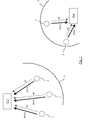
- a) wireless point-to-multipoint network (WIFI for example), as shown in the example of
figure 1 :- i. the central unit CU acts as a central point of a first wireless point-to-multipoint network and receives data (seismic data (noted "DATA") and non-seismic data (noted "QC")) from wireless
seismic acquisition units 2 located in acoverage area 3 of the central unit; - ii. if a "on the ground" data harvesting is implemented, each data harvester equipment DH (carried by an operator of a field team, also referred to as "harvester") acts as a central point of a second wireless point-to-multipoint network and receives data (seismic data (noted "DATA") and non-seismic data (noted "QC")) from wireless
seismic acquisition units 2 located in acoverage area 5 of the harvester equipment;
- i. the central unit CU acts as a central point of a first wireless point-to-multipoint network and receives data (seismic data (noted "DATA") and non-seismic data (noted "QC")) from wireless
- b) wireless cellular network: the wireless seismic acquisition units behave as mobile stations of the wireless cellular network, and can send data (seismic data and non-seismic data) to the central unit, via the infrastructure of the wireless cellular network; and
- c) wireless multi-hop network, as disclosed in
US8,238,197B2 and shown in the example offigure 2 : wirelessseismic acquisition units 2 andbase stations 7 are nodes of a wireless multi-hop network (i.e. they are configured to communicate with surrounding nodes through wireless links). Seismic data (noted "DATA") are forwarded by the wirelessseismic acquisition units 2 until they reach one of thebase stations 7. In other words, each wirelessseismic acquisition unit 2 send its seismic data to abase station 7 via a multi-hop path comprising a sequence of wireless seismic acquisition units. Eachbase station 7 is capable of transferring the received seismic data to a central unit CU (also referred to as "central control and recording system") by any suitable method (e.g. Ethernet, USB, fiber-optic link, wireless interface such as IEEE 802.11, etc.).US8,238,197B2 is silent about the transmission of the non-seismic data (e.g. QC data). - The wired implementation and the wireless implementation (whatever the kind of network used) have drawbacks discussed below.
- Currently, in the wired implementation, the paths from the nodes to the central unit (i.e. seismic acquisition unit) are the same for the seismic data and the non-seismic data (e.g. QC data). That means that the non-seismic data are collected by the central unit which also collects and processes the seismic data. In other words, all the information is centralized in the central unit. A drawback is that the field team shall always communicate with the lab team that manages the central unit in order to obtain information (e.g. non-seismic data, but possibly also seismic data) concerning the seismic acquisition units deployed on the field. In other words, a field operator (of the field team) is not able to retrieve and process the non-seismic data coming from the seismic acquisition units, without any communication with the lab team. Thus, the field operator is not autonomous to manage the seismic acquisition units on the field.
- Currently, when a wireless point-to-multipoint network is used in the wireless implementation, with the central unit (CU) acting as a central point (above case a-i and left side of
figure 1 ), a drawback is that only wireless seismic acquisition units located in the coverage area of the central unit can access the wireless point-to-multipoint network and send their data to the central unit. Another drawback is that the field team has to communicate with the lab team (that manages the central unit) in order to obtain information (e.g. non-seismic data, but possibly also seismic data) concerning the wireless seismic acquisition units deployed on the field. Therefore, as for the wired implementation, the field operator is not able to retrieve and process the non-seismic data coming from the seismic acquisition units, without any communication with the lab team. - Currently, when a wireless point-to-multipoint network is used in the wireless implementation, with the harvester equipment (DH) acting as a central point (above case a-ii and right side of
figure 1 ), the field team can directly collect seismic data and non-seismic data on the field. This case makes the field team more autonomous. However, it has other drawbacks: the wireless seismic acquisition units shall be configured (e.g. IP address or WIFI parameters or any network configuration parameters) in order to communicate with the harvester equipment; only wireless seismic acquisition units located in the coverage area of the harvester equipment can access the wireless point-to-multipoint network and send their data to the harvester equipment; the number of wireless seismic acquisition units that the harvester equipment can manage on the field is limited (e.g. one dozen); and the wireless seismic acquisition units located in harsh environment (forest, dense vegetation, etc.) are not accessible by the harvester equipment (i.e. all of them cannot be reached by the harvester equipment). - Currently, when a wireless cellular network is used in the wireless implementation (above case b), a main drawback is that a heavy infrastructure must be deployed on tens of km2 areas to harvest all the data in real time. Moreover, the field team has to communicate with the lab team (that manages the central unit) in order to obtain information (e.g. non-seismic data, but possibly also seismic data) concerning the wireless seismic acquisition units deployed on the field. Therefore, as for the wired implementation, the field operator is not able to retrieve and process the non-seismic data coming from the seismic acquisition units, without any communication with the lab team.
- Currently, when a wireless multi-hop network is used in the wireless implementation (above case c), as disclosed in
US8,238,197B2 , a real time harvesting of the seismic data (DATA), by the central unit, is possible only for a limited number of wireless seismic acquisition units because of the limited bandwidth of such networks and wireless seismic acquisition units suffer from high power consumption. The number of wireless seismic acquisition units deployed on the field is thus limited. Moreover, as this is a centralized configuration, the field team has to communicate with the lab team (that manages the central unit) in order to obtain information concerning the wireless seismic acquisition units deployed on the field. Therefore, even if we assume that the technique ofUS8,238,197B2 is used to transmit the non-seismic data (e.g. QC data) together with the seismic data (DATA), the field operator is not able to retrieve and process these non-seismic data coming from the seismic acquisition units, without any communication with the lab team. - A particular embodiment of the invention proposes a method for collecting, in a collecting device distinct from a central unit, data coming from a plurality of seismic acquisition units. The method comprises a step of assigning at least one device as a sink unit. For a given sink unit, the method comprises the following steps for data specific to at least one seismic acquisition unit not assigned as a sink unit:
- transmitting said specific data from said at least one seismic acquisition unit to said given sink unit, via a radio path established in a radio multi-hop network built at least with said given sink unit and said plurality of seismic acquisition units; and
- transmitting said specific data from said given sink unit to said collecting device, via a link.
- Thus, this particular embodiment relies on a wholly novel and inventive approach combining:
- a radio multi-hop network (seismic acquisition units being nodes of this network), used to send data (specific to these seismic acquisition units) towards a sink unit; and
- a link between the sink unit and the collecting device, this link being used to send to the collecting device the data collected by the sink unit (thanks to the radio multi-hop network).
- Thus, a field operator who uses the collecting device (e.g. a harvester equipment) can retrieve and process data coming from the seismic acquisition units, without any communication with the lab team (that manages the central unit). The field operator is more autonomous to manage the seismic acquisition units on the field.
- Moreover, the use of a radio multi-hop network provides several advantages, and notably:
- the collecting device can manage seismic acquisition units even though they are located in harsh environment. Indeed, each seismic acquisition unit can be connected to the radio multi-hop network even in harsh environment;
- it does not require configuring the seismic acquisition units in order to enable them to communicate with the sink unit. Indeed, a radio multi-hop network is able to self-configure, self-organize and self-health (no need to configure a seismic acquisition unit to enter it in the radio multi-hop network);
- creation of the best network with respect to radio path, adapted to the environment.
- According to a particular feature, said at least one device assigned as a sink unit is a seismic acquisition unit of said plurality.
- Thus all seismic acquisition units can play the role of sink unit. All the nodes of the radio multi-hop network (i.e. all the seismic acquisition units) are identical, so there is no need for specific equipment.
- According to a particular feature, said specific data are non-seismic data.
- Thus there is a gain in autonomy for the field operators who can repair or change the seismic acquisition units of the spread thanks to the non-seismic data collected, on the field, by the collecting device.
- Moreover, this collecting device (e.g. harvester equipment) can be an equipment that doesn't collect and process seismic data. This allows two distinct networks of data to coexist, one for seismic data and the other for non-seismic data.
- The fact that the radio multi-hop network is used only for the non-seismic data (e.g. QC data) allows the collecting device to manage a higher number (improvement from dozens to hundreds) of seismic acquisition units, compared with the known solution of the harvester equipment acting as a central point of a wireless point-to-multipoint network (above case a-ii). Indeed, contrary to the seismic data, the non-seismic data is of small size, does not need to be transferred immediately, nor dated accurately, and does not need to be secured.
- In an alternative embodiment, said specific data are both non-seismic data and seismic data, implying that both the radio multi-hop network and the link between the sink unit and the collecting device have a sufficient bandwidth.
- According to a particular feature, said non-seismic data are Quality Control data. This list is not exhaustive.
- According to a particular feature, said link between said given sink unit and said collecting device belongs to the group comprising wired links and wireless links.
- Thus any kind of link can be used.
- According to a particular feature, said given sink unit is a wireless seismic acquisition unit, and in that said link between said given sink unit and said collecting device is a wireless link comprised in a point-to-multipoint wireless network deployed between said collecting device, acting as a central point, and at least said given sink unit which is located in a coverage area of said collecting device.
- In this particular implementation, the radio multi-hop network (between wireless seismic acquisition units and the sink unit) is combined in an ingenious way with a point-to-multipoint wireless network (between the sink unit and the collecting device).
- According to a particular feature, when at least two devices are each assigned as a sink unit, it comprises a step of selecting one of said sink units by each seismic acquisition unit not assigned as a sink unit, said step of selecting being carried out according to at least one selection criterion belonging to the group comprising:
- selection criteria based on sink unit priorities, each sink unit being affected a different priority level; and
- selection criteria based on quality of radio paths to each sink unit.
- Thus each seismic acquisition units sends its aforesaid specific data to only one sink unit. The step of selecting can be carried out several times allowing a change of selected sink unit for a given seismic acquisition unit. For example, due to an attenuation of the signal path between the given seismic acquisition unit and a currently selected sink unit, another sink unit is selected (if any) and the given seismic acquisition unit switches to the newly selected sink unit.
- Another particular embodiment of the invention proposes a seismic data acquisition system comprising:
- a collecting device, distinct from a central unit, for collecting data coming from a plurality of seismic acquisition units;
- at least one sink unit connected to the collecting device via a link; and
- a radio multi-hop network built at least with said at least one sink unit and said plurality of seismic acquisition units.
- At least one seismic acquisition unit, not assigned as a sink unit, is configured to transmit specific data to said at least one sink unit, via a radio path established in a radio multi-hop network. Said at least one sink unit is configured to transmit said specific data to said collecting device via said link.
- Other features and advantages of embodiments of the invention shall appear from the following description, given by way of indicative and non-exhaustive examples and from the appended drawings, of which:
-
Figure 1 , already described with reference to the prior art, presents an example of known wireless implementation using wireless point-to-multipoint networks (one with the central unit acting as a central point, and the other with the harvester equipment acting as a central point); -
Figure 2 , already described with reference to the prior art, presents an example of known wireless implementation using a wireless multi-hop network; -
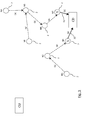
Figure 3 is a partial view of a seismic data acquisition system in which is implemented a harvesting technique (i.e. a method for collecting) according to a first particular embodiment of the invention; -
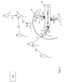
Figure 4 is a partial view of a seismic data acquisition system in which is implemented a harvesting technique (i.e. a method for collecting) according to a second particular embodiment of the invention; -
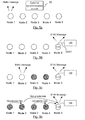
Figures 5a to 5d illustrate successive steps of a harvesting technique (method for collecting) according to the aforesaid first or second particular embodiment of the invention. - In all of the figures of the present document, identical elements and steps are designated by the same numerical reference sign.
-
Figure 3 is a partial view of a seismic data acquisition system in which is implemented a harvesting technique (i.e. a method for collecting) according to a first particular embodiment of the invention. - The seismic data acquisition system comprises notably:
- a central unit referenced CU;
- a (or at least one) harvester equipment, acting as a collecting device and referenced CD; and
- seismic acquisition units referenced 2.
- In this first embodiment, we assume the
seismic acquisition units 2 are of the wireless type and the specific data collected by the harvester equipment CD are non-seismic data, and more particularly QC data (referenced QC). - The present invention is not limited to these examples, and in alternative embodiments, for example, the seismic acquisition units can be of the wired type, and/or the specific data collected can be seismic data, or a combination of non-seismic data (e.g. QC data and/or any other non-seismic data) and seismic data.
- According to the proposed technique, a radio multi-hop network is built, having as nodes the plurality of
seismic acquisition units 2. The radio multi-hop network also comprises at least one special node, assigned as a sink unit referenced S. The central unit CU and the harvester equipment CD are not part of the wireless multi-hop network. - In the first embodiment illustrated in
figure 3 , each sink unit S can communicate with the harvester equipment CD, via a wired link 31 (e.g. an Ethernet link). - In the first embodiment illustrated in
figure 3 , there are two sink units S, and each of them is one of theseismic acquisition units 2. The present invention is not limited to this example, and in one or more alternative embodiments one sink unit or more than two sink units can be used, and/or a sink unit can be a device (node of the radio multi-hop network) which is not one of the seismic acquisition units. - The operation of the system is as follows: each
seismic acquisition unit 2 not assigned as a sink unit transmits its QC data to one of the sink unit S, via a radio path established in the radio multi-hop network; then this sink unit S transmits these QC data to the harvester equipment (CD), via thelink 31. - In the example of
figure 3 , the QC data of the seismic acquisition unit referenced N1 are sent to the seismic acquisition unit referenced N3, assigned as a sink unit S, via a radio path comprising a sequence of seismic acquisition units referenced N1, N2 and N3. The QC data of the seismic acquisition unit referenced N4 are sent to the seismic acquisition unit referenced N7, assigned as a sink unit S, via a radio path comprising a sequence of seismic acquisition units referenced N4, N5, N6 and N7. The QC data of the seismic acquisition unit referenced N8 are sent to the seismic acquisition unit referenced N7, assigned as a sink unit S, via a radio path comprising a sequence of seismic acquisition units referenced N8, N5, N6 and N7. - The proposed technique can be implemented with several harvester equipments (CD) operating simultaneously, each connected to one or several sink units S.
- In the first embodiment described above and illustrated in
figure 3 , the proposed solution is one or several first networks specific to the QC data, and each comprising a harvester equipment CD and several seismic acquisition units 2 (one of which being assigned as a sink unit so as to communicate through awired link 31 with the harvester equipment CD). This or these first networks coexist with a second network allowing the central unit CU or a harvester equipment DH according to the prior art to collect the seismic data DATA (and possibly also the non-seismic data QC). This second network can be of any known type. - For example, the second network is a wireless point-to-multipoint network (WIFI for example) as shown in
figure 1 , and in this case, in addition to the components enabling them to act as nodes of the radio multi-hop network, each seismic acquisition unit 2 (or some of them) comprises components enabling it to transmit data (e.g. seismic data (DATA) and QC data) in a wireless point-to-multipoint network (WIFI for example) as in the known technique offigure 1 : - towards the central unit CU acting as a central point of a first wireless point-to-multipoint network, if the wireless
seismic acquisition unit 2 is located in a coverage area of the central unit; - towards a harvester equipment DH according to the prior art, acting as a central point of a second wireless point-to-multipoint network, if the wireless
seismic acquisition unit 2 is located in a coverage area of the harvester equipment. -
Figure 4 is a partial view of a seismic data acquisition system in which is implemented a harvesting technique (i.e. a method for collecting) according to a second particular embodiment of the invention. - This second embodiment differs from the first one in that the link between each sink unit S and the harvester equipment CD is a wireless link 41 (e.g. a radio link (e.g. WIFI), an optical link, etc.).
- In a particular implementation of the second embodiment, the
wireless link 41 is comprised in a point-to-multipoint wireless network deployed between the harvester equipment CD, acting as a central point, and one or several sink units S located in acoverage area 42 of the harvester equipment CD. In other words, in addition to the components enabling each sink unit S to act as a node of the radio multi-hop network, each sink unit S comprises components enabling it to transmit data towards the harvester equipment CD acting as a central point of a wireless point-to-multipoint network (WIFI for example). - In the second embodiment described above and illustrated in
figure 4 , the proposed solution is one or several first networks specific to the QC data, and each comprising a harvester equipment CD and several seismic acquisition units 2 (one of which being assigned as a sink unit so as to communicate through awireless link 41 with the harvester equipment CD). This or these first networks coexist with a second network allowing the central unit CU or a harvester equipment DH according to the prior art to collect the seismic data DATA (and possibly also the non-seismic data QC). This second network can be of any known type. - For example, the second network is a wireless point-to-multipoint network (WIFI for example) as shown in
figure 1 , and in this case, the components enabling each sink unit S to transmit data towards the harvester equipment CD can also be used to enable this sink unit S (which is a wireless seismic acquisition unit 2) to transmit data (e.g. seismic data (DATA) and QC data) : - towards the central unit CU acting as a central point of a first wireless point-to-multipoint network, if the sink unit S is located in a coverage area of the central unit;
- towards a harvester equipment DH according to the prior art, acting as a central point of a second wireless point-to-multipoint network, if the sink unit S is located in a coverage area of the harvester equipment.
- In the particular case shown in
figure 4 , the harvester equipment is a combination of: - a harvester equipment CD according to the proposed solution, used to collect the non-seismic data QC of some wireless seismic acquisition units. Each of the sink units in the coverage area of the harvester equipment CD (N3 and N7 in this example) collects QC data on a distinct multi-hop network and transmit them to the harvester equipment CD, e.g. using WIFI; and
- a harvester equipment DH according to the prior art, used to collect the seismic data DATA (and possibly also the non-seismic data QC) of the wireless seismic acquisition unit located in its coverage area (N3, N7 and N9 in this example).
- More generally, any kind of wired link (Ethernet, optical fiber, ...) or wireless link (WIFI, Bluetooth, 3G, ...) can be used for the link between the collecting device and the sink unit.
-
Figures 5a to 5d illustrate successive steps of a harvesting technique (method for collecting) according to the aforesaid first or second particular embodiment of the invention (i.e. implemented in the seismic data acquisition system offigure 3 or4 ). - As an illustrative and simplified example, we consider a radio multi-hop network comprising five seismic acquisition units, also referred to as nodes in the following description, and referenced "
Node 1" to "Node 5". - The method for self-configuration and self-organization of the radio multi-hop network consists in several steps detailed below.
- In a first step shown in
figure 5a , the nodes wait for synchronization with an external synchronized source 50 (this source could be a GPS receiver). As soon as a node is synchronized, it sends a "Hello message" periodically to find a route to the sink and discover his neighbours. - In a second step shown in
figure 5b , a node is assigned as a sink node (Node 5 in this example). For example, a node declares itself as a sink node on the basis of a predetermined criterion (e.g. the closest node from the harvester equipment CD which will collect the non-seismic QC data, or the node having the best radio signal strength). In an alternative embodiment, a node becomes automatically a sink unit as soon as it is wirelessly connected or cabled to the harvester equipment CD. A link 31 (seefigure 3 ) or 41 (seefigure 4 ) between the sink node and the harvester equipment CD is established. This link can be a wired link (e.g. an Ethernet link) or a wireless link (e.g. a radio link or any other media). - As soon as a node is assigned as a sink node, it sends a "SINK message" periodically. Each other node, when receiving this "SINK message", directly from the sink node or relayed from neighbour nodes, is able to know at how many hops it is located from the sink node.
- In a third step shown in
figure 5c , the nodes not assigned as a sink node (i.e.Node 1 toNode 4 in the shown example) search the best route to reach the sink node, using the received "Hello messages" and "SINK message". For that, each node which is not located in the coverage area of the sink node: discovers its radio neighbours, selects the best radio neighbours (e.g. the ones having the best radio signal strength) and search the best path (e.g. the shortest one) to the sink node via one of the selected best radio neighbours. For example, let consider data to be transmitted from a node A to a sink unit, and two neighbour nodes B and C of node A. Node A knows the status of nodes B and C (each node B and C knows the number of hop to reach the sink unit, the shortest path, the battery levels of nodes on the path, etc.). One or several of fields defining the status of nodes B and C is (are) used as selection criteria by node A to select the best route to reach the sink node. In a particular embodiment, node A can also use as supplemental selection criteria the quality radio path between node A and each of the neighbour nodes B and C. - In the example shown in
figure 5c , two nodes (Node 3 and Node 4) indicated in grey colour have found a route to the sink node and have started building the network. - In a fourth step (routing) shown in
figure 5d , the best radio path from each node to the sink node is established. A node only knows the route to his closest neighbours. - Then, the non-seismic data are sent periodically and propagate along the aforesaid radio paths, from neighbours to neighbours, until the sink node. Then the non-seismic data are collected by the harvester equipment CD, via the
link 31/41. - Several harvester equipment CD can be used on the field, each with one or several sink nodes. So in particular embodiments, multiple sink nodes can be available on the field.
- Nodes (other than sink nodes) cannot send their non-seismic data to several sink nodes. A node can select a sink node according to one or several parameters, e.g.:
- priority of the sink node : each sink node can be affected a distinct priority level such that non-seismic data are sent to the sink node having the highest priority;
- quality of route to the sink node : non-seismic data are sent to the sink node that offers the best route to it. Quality of the route can be based on one or several of the following parameters: number of hops to reach the sink node, RF path loss of the hops, battery level of relay nodes, ...;
- etc.
- For a given node, the selected sink unit can change over time. For example, due to a loss of signal quality on the path between the node and the currently selected sink unit, the node selects another sink unit (if any).
- An exemplary embodiment of the present disclosure provides a technique for collecting, in a collecting device (e.g. a harvester equipment) distinct from a central unit, data coming from a plurality of seismic acquisition units.
- An exemplary embodiment of the disclosure provides a technique of this kind allowing a field operator to retrieve and process data coming from seismic acquisition units, without any communication with the lab team (that manages the central unit).
- An exemplary embodiment of the disclosure provides a technique of this kind enabling the collecting device to manage a higher number of seismic acquisition units, compared with the known solution of the harvester equipment acting as a central point of a wireless point-to-multipoint network (above case a-ii).
- An exemplary embodiment of the disclosure provides a technique of this kind enabling the collecting device to manage seismic acquisition units even though they are located in harsh environment.
- An exemplary embodiment of the disclosure provides a technique of this kind that allows two networks of data (one for seismic data and the other for non-seismic data) to coexist.
- The various systems, units, devices, etc. described herein may be implemented on any form of computer or computers, and their components may be implemented as dedicated applications or in client-server architectures, including a web-based architecture, and can include functional programs, codes, and code segments. Any of the computers may comprise one or more of a processor, a memory for storing program data and executing it, a permanent storage such as a disk drive, a communications port for handling communications with external devices, and user interface devices, including a display, keyboard, mouse, etc. When software modules are involved, these software modules may be stored as program instructions or computer readable codes executable on the processor on a non-transitory computer-readable media such as read-only memory (ROM), random-access memory (RAM), CD-ROMs, magnetic tapes, floppy disks, and optical data storage devices. The computer readable recording medium can also be distributed over network coupled computer systems so that the computer readable code is stored and executed in a distributed fashion. This media is readable by the computer, stored in the memory, and executed by the processor. For example one or more parts of the system may be implemented by a computer processor with associated memory. In other exemplary embodiments, functions are implemented by hardware only, such as logic gates of an integrated circuit.
- Although the present disclosure has been described with reference to one or more examples, workers skilled in the art will recognize that changes may be made in form and detail without departing from the scope of the disclosure and/or the appended claims.
Claims (11)
- A method for collecting, in a collecting device (CD) distinct from a central unit (CU), data coming from a plurality of seismic acquisition units, characterized in that the method comprises a step of assigning at least one device as a sink unit (S), and in that, for a given sink unit, the method comprises the following steps for data specific to at least one seismic acquisition unit not assigned as a sink unit:- transmitting said specific data from said at least one seismic acquisition unit to said given sink unit, via a radio path established in a radio multi-hop network built at least with said given sink unit and said plurality of seismic acquisition units; and- transmitting said specific data from said given sink unit to said collecting device, via a link (31; 41).
- The method according to claim 1, characterized in that said at least one device assigned as a sink unit is a seismic acquisition unit of said plurality.
- The method according to any one of the claims 1 to 2, characterized in that said specific data are non-seismic data.
- The method according to claim 3, characterized in that said non-seismic data are Quality Control data.
- The method according to any one of the claims 1 to 4, characterized in that said link between said given sink unit and said collecting device belongs to the group comprising wired links and wireless links.
- The method according to claim 2, characterized in that said given sink unit is a wireless seismic acquisition unit, and in that said link between said given sink unit and said collecting device is a wireless link comprised in a point-to-multipoint wireless network deployed between said collecting device, acting as a central point, and at least said given sink unit which is located in a coverage area of said collecting device.
- The method according to any one of the claims 1 to 6, characterized in that, when at least two devices are each assigned as a sink unit, the method comprises a step of selecting one of said at least two sink units by each seismic acquisition unit not assigned as a sink unit, said step of selecting being carried out according to at least one selection criterion belonging to the group comprising:- selection criteria based on sink unit priorities, each sink unit being affected a different priority level; and- selection criteria based on quality of radio paths to each sink unit.
- A seismic data acquisition system comprising:- a collecting device, distinct from a central unit, configured to collect data coming from a plurality of seismic acquisition units;- at least one sink unit connected to the collecting device via a link; and- a radio multi-hop network built at least with said at least one sink unit and said plurality of seismic acquisition units;wherein at least one of the seismic acquisition units, not assigned as a sink unit, is configured to transmit specific data to said at least one sink unit, via a radio path established in a radio multi-hop network,
and wherein said at least one sink unit is configured to transmit said specific data to said collecting device via said link. - The seismic data acquisition system according to claim 8, characterized in that said at least one sink unit is a seismic acquisition unit of said plurality.
- The seismic data acquisition system according to any one of the claims 8 to 9, characterized in that said specific data are non-seismic data.
- The seismic data acquisition system according to claim 10, characterized in that said non-seismic data are Quality Control data.
Priority Applications (1)
| Application Number | Priority Date | Filing Date | Title |
|---|---|---|---|
| PL15156337T PL2919039T3 (en) | 2014-03-12 | 2015-02-24 | Method for collecting, in a collecting device distinct from a central unit, data coming from a plurality of seismic acquisition units |
Applications Claiming Priority (2)
| Application Number | Priority Date | Filing Date | Title |
|---|---|---|---|
| US201461951900P | 2014-03-12 | 2014-03-12 | |
| US14/530,176 US9599733B2 (en) | 2014-03-12 | 2014-10-31 | Method for collecting, in a harvester equipment distinct from a central unit, data coming from a plurality of seismic acquisition units |
Publications (2)
| Publication Number | Publication Date |
|---|---|
| EP2919039A1 true EP2919039A1 (en) | 2015-09-16 |
| EP2919039B1 EP2919039B1 (en) | 2022-01-05 |
Family
ID=52577700
Family Applications (1)
| Application Number | Title | Priority Date | Filing Date |
|---|---|---|---|
| EP15156337.6A Active EP2919039B1 (en) | 2014-03-12 | 2015-02-24 | Method for collecting, in a collecting device distinct from a central unit, data coming from a plurality of seismic acquisition units |
Country Status (6)
| Country | Link |
|---|---|
| US (1) | US9599733B2 (en) |
| EP (1) | EP2919039B1 (en) |
| CN (1) | CN104914461B (en) |
| CA (1) | CA2883071C (en) |
| PL (1) | PL2919039T3 (en) |
| RU (1) | RU2669513C2 (en) |
Families Citing this family (2)
| Publication number | Priority date | Publication date | Assignee | Title |
|---|---|---|---|---|
| CN110716229A (en) * | 2019-11-06 | 2020-01-21 | 吉林大学 | Seismic data transmission system based on UWB multi-hop network architecture |
| CN115128664B (en) | 2022-09-01 | 2022-11-08 | 中国科学院地质与地球物理研究所 | Seismic Acquisition System Based on Frequency Domain Widening MEMS Sensor |
Citations (4)
| Publication number | Priority date | Publication date | Assignee | Title |
|---|---|---|---|---|
| WO2007044459A2 (en) * | 2005-10-07 | 2007-04-19 | Wireless Seismic | Wireless exploration seismic system |
| US7224642B1 (en) * | 2006-01-26 | 2007-05-29 | Tran Bao Q | Wireless sensor data processing systems |
| US20080080312A1 (en) * | 2006-09-29 | 2008-04-03 | Ion Geophysical Corporation | Seismic Data Acquisition Using Time-Division Multiplexing |
| US20080219094A1 (en) * | 2007-03-08 | 2008-09-11 | Simon Barakat | Systems and Methods for Seismic Data Acquisition Employing Asynchronous, Decoupled Data Sampling and Transmission |
Family Cites Families (31)
| Publication number | Priority date | Publication date | Assignee | Title |
|---|---|---|---|---|
| US3062315A (en) | 1959-01-05 | 1962-11-06 | Texaco Inc | Radio-link system of seismic exploration |
| GB2055467A (en) | 1979-07-16 | 1981-03-04 | Fairfield Ind Inc | Geophysical exploration utilizing telemetered seismic data and airborne receivers |
| US4236234A (en) | 1979-07-25 | 1980-11-25 | Fairfield Industries, Inc. | Radio frequency seismic gathering system employing an airborne blimp |
| CA1231429A (en) | 1984-11-23 | 1988-01-12 | Ben B. Thigpen | Rf telemetric system |
| FR2671197A1 (en) | 1990-12-28 | 1992-07-03 | Inst Francais Du Petrole | METHOD AND DEVICE FOR SIMPLIFYING THE LOCATION OF AN UNDERGROUND AREA IN THE CONTEXT OF A SEISMIC EXPLORATION. |
| FR2689647B1 (en) | 1992-04-01 | 1997-09-05 | Inst Francais Du Petrole | SYSTEM FOR ACQUIRING AND CENTRALIZING DATA OBTAINED BY A PERMANENT INSTALLATION FOR EXPLORING A GEOLOGICAL TRAINING. |
| FR2692384A1 (en) * | 1992-06-11 | 1993-12-17 | Inst Francais Du Petrole | Data acquisition system provided with decentralized processing means. |
| FR2696839B1 (en) | 1992-10-12 | 1994-12-09 | Inst Francais Du Petrole | Method and system of seismic transmission using concentration units. |
| FR2720518B1 (en) | 1994-05-26 | 1996-07-12 | Inst Francais Du Petrole | Seismic acquisition and transmission system with decentralization of functions. |
| US5724241A (en) | 1996-01-11 | 1998-03-03 | Western Atlas International, Inc. | Distributed seismic data-gathering system |
| US6002640A (en) | 1997-05-15 | 1999-12-14 | Geo-X Systems, Inc. | Seismic data acquisition system |
| FR2781944B1 (en) | 1998-07-29 | 2001-10-05 | Inst Francais Du Petrole | METHOD FOR ACHIEVING A COMPRESSION WITHOUT LOSS OF SIGNALS WITH A LARGE DYNAMIC FOR THEIR TRANSMISSION |
| US20040105533A1 (en) | 1998-08-07 | 2004-06-03 | Input/Output, Inc. | Single station wireless seismic data acquisition method and apparatus |
| CA2374949A1 (en) * | 1999-05-24 | 2000-12-21 | Input/Output, Inc. | Remote control system for seismic acquisition |
| US7813221B2 (en) | 2002-11-22 | 2010-10-12 | Westerngeco L.L.C. | Sensor and recorder communication |
| US7417924B2 (en) * | 2005-04-26 | 2008-08-26 | Westerngeco L.L.C. | Apparatus, systems and methods for determining position of marine seismic acoustic receivers |
| US20060247505A1 (en) | 2005-04-28 | 2006-11-02 | Siddiqui Waqaas A | Wireless sensor system |
| FR2889385B1 (en) * | 2005-07-28 | 2008-09-26 | Sercel Sa | WIRELESS DATA ACQUISITION NETWORK |
| US20080021658A1 (en) | 2006-06-10 | 2008-01-24 | Input/Output, Inc. | Apparatus and Method for Integrating Survey Parameters Into a Header |
| EP2059835A2 (en) | 2006-09-14 | 2009-05-20 | Geco Technology B.V. | Wireless systems and methods for seismic data acquisition |
| US8605546B2 (en) | 2006-09-29 | 2013-12-10 | Inova Ltd. | Seismic data acquisition systems and method utilizing a wireline repeater unit |
| CA2664689A1 (en) | 2006-09-29 | 2008-04-10 | Ion Geophysical Corporation | For in-field control module for managing wireless seismic data acquisition systems and related methods |
| US7715887B2 (en) | 2006-11-14 | 2010-05-11 | Harris Corporation | Low power distribution system for an unattended ground sensor system |
| US20080285385A1 (en) | 2007-05-18 | 2008-11-20 | Cherry J Theodore | Methods and systems for seismic event detection |
| GB0725276D0 (en) | 2007-12-28 | 2008-02-06 | Vibration Technology Ltd | Seismic data recording |
| US8296067B2 (en) | 2008-03-17 | 2012-10-23 | Bp Corporation North America Inc. | Satellite communications with cableless seismographs |
| RU2400777C1 (en) * | 2009-01-21 | 2010-09-27 | Учреждение Российской академии наук Институт динамики геосфер РАН (ИДГ РАН) | Autonomous seismograph with digital registration of seismic data |
| GB2472428A (en) | 2009-08-06 | 2011-02-09 | Wireless Fibre Systems Ltd | Wireless communication via seabed for underwater seismic detection network |
| US20110305114A1 (en) * | 2010-06-11 | 2011-12-15 | Daniel Golparian | Seismic survey communication systems and methods |
| US9400338B2 (en) | 2012-09-18 | 2016-07-26 | Westerngeco L.L.C. | Seismic acquisition system-based unmanned airborne vehicle |
| US8605544B1 (en) | 2012-10-05 | 2013-12-10 | Esg Solutions Inc. | Hybrid seismic sensor network |
-
2014
- 2014-10-31 US US14/530,176 patent/US9599733B2/en active Active
-
2015
- 2015-02-24 EP EP15156337.6A patent/EP2919039B1/en active Active
- 2015-02-24 PL PL15156337T patent/PL2919039T3/en unknown
- 2015-02-25 CA CA2883071A patent/CA2883071C/en active Active
- 2015-03-11 CN CN201510106559.7A patent/CN104914461B/en active Active
- 2015-03-11 RU RU2015108421A patent/RU2669513C2/en active
Patent Citations (5)
| Publication number | Priority date | Publication date | Assignee | Title |
|---|---|---|---|---|
| WO2007044459A2 (en) * | 2005-10-07 | 2007-04-19 | Wireless Seismic | Wireless exploration seismic system |
| US8238197B2 (en) | 2005-10-07 | 2012-08-07 | Wireless Seismic, Inc. | Wireless exploration seismic system |
| US7224642B1 (en) * | 2006-01-26 | 2007-05-29 | Tran Bao Q | Wireless sensor data processing systems |
| US20080080312A1 (en) * | 2006-09-29 | 2008-04-03 | Ion Geophysical Corporation | Seismic Data Acquisition Using Time-Division Multiplexing |
| US20080219094A1 (en) * | 2007-03-08 | 2008-09-11 | Simon Barakat | Systems and Methods for Seismic Data Acquisition Employing Asynchronous, Decoupled Data Sampling and Transmission |
Also Published As
| Publication number | Publication date |
|---|---|
| CN104914461A (en) | 2015-09-16 |
| PL2919039T3 (en) | 2022-04-25 |
| US9599733B2 (en) | 2017-03-21 |
| RU2669513C2 (en) | 2018-10-11 |
| RU2015108421A (en) | 2016-09-27 |
| US20150260865A1 (en) | 2015-09-17 |
| RU2015108421A3 (en) | 2018-09-17 |
| CA2883071A1 (en) | 2015-09-12 |
| CN104914461B (en) | 2019-04-19 |
| CA2883071C (en) | 2022-08-02 |
| EP2919039B1 (en) | 2022-01-05 |
Similar Documents
| Publication | Publication Date | Title |
|---|---|---|
| Razmi et al. | On-board federated learning for dense LEO constellations | |
| Koucheryavy et al. | State of the art and research challenges for public flying ubiquitous sensor networks | |
| KR102896645B1 (en) | Controll device and method for a plurality of robots | |
| CA2783145A1 (en) | Wireless mesh network and method for remote seismic recording | |
| KR102808023B1 (en) | System and method for optimization of mission planning of multi-uav network for data collection and communication relay | |
| CN110716229A (en) | Seismic data transmission system based on UWB multi-hop network architecture | |
| Ferranti et al. | Hiro-net: Self-organized robotic mesh networking for internet sharing in disaster scenarios | |
| US10608875B2 (en) | Method for dynamically configuring a network comprising a plurality of subnets | |
| Savazzi et al. | Wireless geophone networks for high-density land acquisition: Technologies and future potential | |
| Sujit et al. | Joint route planning for UAV and sensor network for data retrieval | |
| US20090265140A1 (en) | Wireless data acquisition network and operating methods | |
| CN109314908A (en) | Communication systems and wireless network engineering aids | |
| EP2919039B1 (en) | Method for collecting, in a collecting device distinct from a central unit, data coming from a plurality of seismic acquisition units | |
| EP2034336A1 (en) | Data transmission system | |
| Kuntze et al. | Situation responsive networking of mobile robots for disaster management | |
| JP5104144B2 (en) | Wireless network communication system, communication method and program | |
| EP2887100B1 (en) | Method for downloading data to a central unit in a seismic data acquisition system | |
| JP2022055720A (en) | Information processing system and information processing method | |
| Nguyen et al. | UAV-aided sensory data aggregation: incremental clustering and scheduling approach | |
| Hematian et al. | A clustering-based device-to-device communication to support diverse applications | |
| JP6852864B2 (en) | Robot monitoring and control system | |
| KR101657006B1 (en) | Mobile node, Method of managing movement of mobile nodes and system thereof | |
| US20170134259A1 (en) | Method for Managing a Network, and Node for Implementing Said Method | |
| KR102120435B1 (en) | Method for scheduling of wireless sensor network and controller of wireless sensor network | |
| JP2013232758A (en) | Data collection system |
Legal Events
| Date | Code | Title | Description |
|---|---|---|---|
| PUAI | Public reference made under article 153(3) epc to a published international application that has entered the european phase |
Free format text: ORIGINAL CODE: 0009012 |
|
| AK | Designated contracting states |
Kind code of ref document: A1 Designated state(s): AL AT BE BG CH CY CZ DE DK EE ES FI FR GB GR HR HU IE IS IT LI LT LU LV MC MK MT NL NO PL PT RO RS SE SI SK SM TR |
|
| AX | Request for extension of the european patent |
Extension state: BA ME |
|
| 17P | Request for examination filed |
Effective date: 20160315 |
|
| RBV | Designated contracting states (corrected) |
Designated state(s): AL AT BE BG CH CY CZ DE DK EE ES FI FR GB GR HR HU IE IS IT LI LT LU LV MC MK MT NL NO PL PT RO RS SE SI SK SM TR |
|
| STAA | Information on the status of an ep patent application or granted ep patent |
Free format text: STATUS: EXAMINATION IS IN PROGRESS |
|
| 17Q | First examination report despatched |
Effective date: 20180911 |
|
| GRAP | Despatch of communication of intention to grant a patent |
Free format text: ORIGINAL CODE: EPIDOSNIGR1 |
|
| STAA | Information on the status of an ep patent application or granted ep patent |
Free format text: STATUS: GRANT OF PATENT IS INTENDED |
|
| INTG | Intention to grant announced |
Effective date: 20211018 |
|
| RIN1 | Information on inventor provided before grant (corrected) |
Inventor name: LE MOINE, FABIEN Inventor name: LOSTANLEN-NOUY, SOPHIE |
|
| GRAS | Grant fee paid |
Free format text: ORIGINAL CODE: EPIDOSNIGR3 |
|
| GRAA | (expected) grant |
Free format text: ORIGINAL CODE: 0009210 |
|
| STAA | Information on the status of an ep patent application or granted ep patent |
Free format text: STATUS: THE PATENT HAS BEEN GRANTED |
|
| AK | Designated contracting states |
Kind code of ref document: B1 Designated state(s): AL AT BE BG CH CY CZ DE DK EE ES FI FR GB GR HR HU IE IS IT LI LT LU LV MC MK MT NL NO PL PT RO RS SE SI SK SM TR |
|
| REG | Reference to a national code |
Ref country code: GB Ref legal event code: FG4D |
|
| REG | Reference to a national code |
Ref country code: CH Ref legal event code: EP |
|
| REG | Reference to a national code |
Ref country code: AT Ref legal event code: REF Ref document number: 1461081 Country of ref document: AT Kind code of ref document: T Effective date: 20220115 |
|
| REG | Reference to a national code |
Ref country code: DE Ref legal event code: R096 Ref document number: 602015076183 Country of ref document: DE |
|
| REG | Reference to a national code |
Ref country code: IE Ref legal event code: FG4D |
|
| REG | Reference to a national code |
Ref country code: LT Ref legal event code: MG9D |
|
| REG | Reference to a national code |
Ref country code: NL Ref legal event code: MP Effective date: 20220105 |
|
| REG | Reference to a national code |
Ref country code: AT Ref legal event code: MK05 Ref document number: 1461081 Country of ref document: AT Kind code of ref document: T Effective date: 20220105 |
|
| PG25 | Lapsed in a contracting state [announced via postgrant information from national office to epo] |
Ref country code: NL Free format text: LAPSE BECAUSE OF FAILURE TO SUBMIT A TRANSLATION OF THE DESCRIPTION OR TO PAY THE FEE WITHIN THE PRESCRIBED TIME-LIMIT Effective date: 20220105 |
|
| PG25 | Lapsed in a contracting state [announced via postgrant information from national office to epo] |
Ref country code: SE Free format text: LAPSE BECAUSE OF FAILURE TO SUBMIT A TRANSLATION OF THE DESCRIPTION OR TO PAY THE FEE WITHIN THE PRESCRIBED TIME-LIMIT Effective date: 20220105 Ref country code: RS Free format text: LAPSE BECAUSE OF FAILURE TO SUBMIT A TRANSLATION OF THE DESCRIPTION OR TO PAY THE FEE WITHIN THE PRESCRIBED TIME-LIMIT Effective date: 20220105 Ref country code: PT Free format text: LAPSE BECAUSE OF FAILURE TO SUBMIT A TRANSLATION OF THE DESCRIPTION OR TO PAY THE FEE WITHIN THE PRESCRIBED TIME-LIMIT Effective date: 20220505 Ref country code: NO Free format text: LAPSE BECAUSE OF FAILURE TO SUBMIT A TRANSLATION OF THE DESCRIPTION OR TO PAY THE FEE WITHIN THE PRESCRIBED TIME-LIMIT Effective date: 20220405 Ref country code: LT Free format text: LAPSE BECAUSE OF FAILURE TO SUBMIT A TRANSLATION OF THE DESCRIPTION OR TO PAY THE FEE WITHIN THE PRESCRIBED TIME-LIMIT Effective date: 20220105 Ref country code: HR Free format text: LAPSE BECAUSE OF FAILURE TO SUBMIT A TRANSLATION OF THE DESCRIPTION OR TO PAY THE FEE WITHIN THE PRESCRIBED TIME-LIMIT Effective date: 20220105 Ref country code: ES Free format text: LAPSE BECAUSE OF FAILURE TO SUBMIT A TRANSLATION OF THE DESCRIPTION OR TO PAY THE FEE WITHIN THE PRESCRIBED TIME-LIMIT Effective date: 20220105 Ref country code: BG Free format text: LAPSE BECAUSE OF FAILURE TO SUBMIT A TRANSLATION OF THE DESCRIPTION OR TO PAY THE FEE WITHIN THE PRESCRIBED TIME-LIMIT Effective date: 20220405 |
|
| PG25 | Lapsed in a contracting state [announced via postgrant information from national office to epo] |
Ref country code: LV Free format text: LAPSE BECAUSE OF FAILURE TO SUBMIT A TRANSLATION OF THE DESCRIPTION OR TO PAY THE FEE WITHIN THE PRESCRIBED TIME-LIMIT Effective date: 20220105 Ref country code: GR Free format text: LAPSE BECAUSE OF FAILURE TO SUBMIT A TRANSLATION OF THE DESCRIPTION OR TO PAY THE FEE WITHIN THE PRESCRIBED TIME-LIMIT Effective date: 20220406 Ref country code: FI Free format text: LAPSE BECAUSE OF FAILURE TO SUBMIT A TRANSLATION OF THE DESCRIPTION OR TO PAY THE FEE WITHIN THE PRESCRIBED TIME-LIMIT Effective date: 20220105 Ref country code: AT Free format text: LAPSE BECAUSE OF FAILURE TO SUBMIT A TRANSLATION OF THE DESCRIPTION OR TO PAY THE FEE WITHIN THE PRESCRIBED TIME-LIMIT Effective date: 20220105 |
|
| PG25 | Lapsed in a contracting state [announced via postgrant information from national office to epo] |
Ref country code: IS Free format text: LAPSE BECAUSE OF FAILURE TO SUBMIT A TRANSLATION OF THE DESCRIPTION OR TO PAY THE FEE WITHIN THE PRESCRIBED TIME-LIMIT Effective date: 20220505 |
|
| REG | Reference to a national code |
Ref country code: DE Ref legal event code: R097 Ref document number: 602015076183 Country of ref document: DE |
|
| REG | Reference to a national code |
Ref country code: BE Ref legal event code: MM Effective date: 20220228 |
|
| PG25 | Lapsed in a contracting state [announced via postgrant information from national office to epo] |
Ref country code: SM Free format text: LAPSE BECAUSE OF FAILURE TO SUBMIT A TRANSLATION OF THE DESCRIPTION OR TO PAY THE FEE WITHIN THE PRESCRIBED TIME-LIMIT Effective date: 20220105 Ref country code: SK Free format text: LAPSE BECAUSE OF FAILURE TO SUBMIT A TRANSLATION OF THE DESCRIPTION OR TO PAY THE FEE WITHIN THE PRESCRIBED TIME-LIMIT Effective date: 20220105 Ref country code: RO Free format text: LAPSE BECAUSE OF FAILURE TO SUBMIT A TRANSLATION OF THE DESCRIPTION OR TO PAY THE FEE WITHIN THE PRESCRIBED TIME-LIMIT Effective date: 20220105 Ref country code: MC Free format text: LAPSE BECAUSE OF FAILURE TO SUBMIT A TRANSLATION OF THE DESCRIPTION OR TO PAY THE FEE WITHIN THE PRESCRIBED TIME-LIMIT Effective date: 20220105 Ref country code: LU Free format text: LAPSE BECAUSE OF NON-PAYMENT OF DUE FEES Effective date: 20220224 Ref country code: EE Free format text: LAPSE BECAUSE OF FAILURE TO SUBMIT A TRANSLATION OF THE DESCRIPTION OR TO PAY THE FEE WITHIN THE PRESCRIBED TIME-LIMIT Effective date: 20220105 Ref country code: DK Free format text: LAPSE BECAUSE OF FAILURE TO SUBMIT A TRANSLATION OF THE DESCRIPTION OR TO PAY THE FEE WITHIN THE PRESCRIBED TIME-LIMIT Effective date: 20220105 Ref country code: CZ Free format text: LAPSE BECAUSE OF FAILURE TO SUBMIT A TRANSLATION OF THE DESCRIPTION OR TO PAY THE FEE WITHIN THE PRESCRIBED TIME-LIMIT Effective date: 20220105 |
|
| PLBE | No opposition filed within time limit |
Free format text: ORIGINAL CODE: 0009261 |
|
| STAA | Information on the status of an ep patent application or granted ep patent |
Free format text: STATUS: NO OPPOSITION FILED WITHIN TIME LIMIT |
|
| PG25 | Lapsed in a contracting state [announced via postgrant information from national office to epo] |
Ref country code: AL Free format text: LAPSE BECAUSE OF FAILURE TO SUBMIT A TRANSLATION OF THE DESCRIPTION OR TO PAY THE FEE WITHIN THE PRESCRIBED TIME-LIMIT Effective date: 20220105 |
|
| 26N | No opposition filed |
Effective date: 20221006 |
|
| PG25 | Lapsed in a contracting state [announced via postgrant information from national office to epo] |
Ref country code: IE Free format text: LAPSE BECAUSE OF NON-PAYMENT OF DUE FEES Effective date: 20220224 |
|
| PG25 | Lapsed in a contracting state [announced via postgrant information from national office to epo] |
Ref country code: SI Free format text: LAPSE BECAUSE OF FAILURE TO SUBMIT A TRANSLATION OF THE DESCRIPTION OR TO PAY THE FEE WITHIN THE PRESCRIBED TIME-LIMIT Effective date: 20220105 Ref country code: BE Free format text: LAPSE BECAUSE OF NON-PAYMENT OF DUE FEES Effective date: 20220228 |
|
| PG25 | Lapsed in a contracting state [announced via postgrant information from national office to epo] |
Ref country code: IT Free format text: LAPSE BECAUSE OF FAILURE TO SUBMIT A TRANSLATION OF THE DESCRIPTION OR TO PAY THE FEE WITHIN THE PRESCRIBED TIME-LIMIT Effective date: 20220105 |
|
| PG25 | Lapsed in a contracting state [announced via postgrant information from national office to epo] |
Ref country code: HU Free format text: LAPSE BECAUSE OF FAILURE TO SUBMIT A TRANSLATION OF THE DESCRIPTION OR TO PAY THE FEE WITHIN THE PRESCRIBED TIME-LIMIT; INVALID AB INITIO Effective date: 20150224 |
|
| PG25 | Lapsed in a contracting state [announced via postgrant information from national office to epo] |
Ref country code: MK Free format text: LAPSE BECAUSE OF FAILURE TO SUBMIT A TRANSLATION OF THE DESCRIPTION OR TO PAY THE FEE WITHIN THE PRESCRIBED TIME-LIMIT Effective date: 20220105 Ref country code: CY Free format text: LAPSE BECAUSE OF FAILURE TO SUBMIT A TRANSLATION OF THE DESCRIPTION OR TO PAY THE FEE WITHIN THE PRESCRIBED TIME-LIMIT Effective date: 20220105 |
|
| PG25 | Lapsed in a contracting state [announced via postgrant information from national office to epo] |
Ref country code: MT Free format text: LAPSE BECAUSE OF FAILURE TO SUBMIT A TRANSLATION OF THE DESCRIPTION OR TO PAY THE FEE WITHIN THE PRESCRIBED TIME-LIMIT Effective date: 20220105 |
|
| PG25 | Lapsed in a contracting state [announced via postgrant information from national office to epo] |
Ref country code: TR Free format text: LAPSE BECAUSE OF FAILURE TO SUBMIT A TRANSLATION OF THE DESCRIPTION OR TO PAY THE FEE WITHIN THE PRESCRIBED TIME-LIMIT Effective date: 20220105 |
|
| REG | Reference to a national code |
Ref country code: CH Ref legal event code: U11 Free format text: ST27 STATUS EVENT CODE: U-0-0-U10-U11 (AS PROVIDED BY THE NATIONAL OFFICE) Effective date: 20260301 |
|
| PGFP | Annual fee paid to national office [announced via postgrant information from national office to epo] |
Ref country code: GB Payment date: 20260219 Year of fee payment: 12 |
|
| PGFP | Annual fee paid to national office [announced via postgrant information from national office to epo] |
Ref country code: DE Payment date: 20260218 Year of fee payment: 12 |
|
| PGFP | Annual fee paid to national office [announced via postgrant information from national office to epo] |
Ref country code: FR Payment date: 20260218 Year of fee payment: 12 |
|
| PGFP | Annual fee paid to national office [announced via postgrant information from national office to epo] |
Ref country code: CH Payment date: 20260301 Year of fee payment: 12 |
|
| PGFP | Annual fee paid to national office [announced via postgrant information from national office to epo] |
Ref country code: PL Payment date: 20260213 Year of fee payment: 12 |