EP2919033A1 - Method and apparatus for displaying plurality of different images of object - Google Patents
Method and apparatus for displaying plurality of different images of object Download PDFInfo
- Publication number
- EP2919033A1 EP2919033A1 EP14182595.0A EP14182595A EP2919033A1 EP 2919033 A1 EP2919033 A1 EP 2919033A1 EP 14182595 A EP14182595 A EP 14182595A EP 2919033 A1 EP2919033 A1 EP 2919033A1
- Authority
- EP
- European Patent Office
- Prior art keywords
- image
- interest
- region
- displayed
- displaying
- Prior art date
- Legal status (The legal status is an assumption and is not a legal conclusion. Google has not performed a legal analysis and makes no representation as to the accuracy of the status listed.)
- Granted
Links
Images



Classifications
-
- A—HUMAN NECESSITIES
- A61—MEDICAL OR VETERINARY SCIENCE; HYGIENE
- A61B—DIAGNOSIS; SURGERY; IDENTIFICATION
- A61B8/00—Diagnosis using ultrasonic, sonic or infrasonic waves
- A61B8/46—Ultrasonic, sonic or infrasonic diagnostic devices with special arrangements for interfacing with the operator or the patient
- A61B8/461—Displaying means of special interest
- A61B8/463—Displaying means of special interest characterised by displaying multiple images or images and diagnostic data on one display
-
- A—HUMAN NECESSITIES
- A61—MEDICAL OR VETERINARY SCIENCE; HYGIENE
- A61B—DIAGNOSIS; SURGERY; IDENTIFICATION
- A61B8/00—Diagnosis using ultrasonic, sonic or infrasonic waves
- A61B8/46—Ultrasonic, sonic or infrasonic diagnostic devices with special arrangements for interfacing with the operator or the patient
- A61B8/467—Ultrasonic, sonic or infrasonic diagnostic devices with special arrangements for interfacing with the operator or the patient characterised by special input means
-
- A—HUMAN NECESSITIES
- A61—MEDICAL OR VETERINARY SCIENCE; HYGIENE
- A61B—DIAGNOSIS; SURGERY; IDENTIFICATION
- A61B8/00—Diagnosis using ultrasonic, sonic or infrasonic waves
- A61B8/46—Ultrasonic, sonic or infrasonic diagnostic devices with special arrangements for interfacing with the operator or the patient
- A61B8/467—Ultrasonic, sonic or infrasonic diagnostic devices with special arrangements for interfacing with the operator or the patient characterised by special input means
- A61B8/469—Ultrasonic, sonic or infrasonic diagnostic devices with special arrangements for interfacing with the operator or the patient characterised by special input means for selection of a region of interest
-
- G—PHYSICS
- G01—MEASURING; TESTING
- G01S—RADIO DIRECTION-FINDING; RADIO NAVIGATION; DETERMINING DISTANCE OR VELOCITY BY USE OF RADIO WAVES; LOCATING OR PRESENCE-DETECTING BY USE OF THE REFLECTION OR RERADIATION OF RADIO WAVES; ANALOGOUS ARRANGEMENTS USING OTHER WAVES
- G01S7/00—Details of systems according to groups G01S13/00, G01S15/00, G01S17/00
- G01S7/52—Details of systems according to groups G01S13/00, G01S15/00, G01S17/00 of systems according to group G01S15/00
- G01S7/52017—Details of systems according to groups G01S13/00, G01S15/00, G01S17/00 of systems according to group G01S15/00 particularly adapted to short-range imaging
- G01S7/52053—Display arrangements
- G01S7/52057—Cathode ray tube displays
- G01S7/5206—Two-dimensional coordinated display of distance and direction; B-scan display
- G01S7/52063—Sector scan display
-
- G—PHYSICS
- G01—MEASURING; TESTING
- G01S—RADIO DIRECTION-FINDING; RADIO NAVIGATION; DETERMINING DISTANCE OR VELOCITY BY USE OF RADIO WAVES; LOCATING OR PRESENCE-DETECTING BY USE OF THE REFLECTION OR RERADIATION OF RADIO WAVES; ANALOGOUS ARRANGEMENTS USING OTHER WAVES
- G01S7/00—Details of systems according to groups G01S13/00, G01S15/00, G01S17/00
- G01S7/52—Details of systems according to groups G01S13/00, G01S15/00, G01S17/00 of systems according to group G01S15/00
- G01S7/52017—Details of systems according to groups G01S13/00, G01S15/00, G01S17/00 of systems according to group G01S15/00 particularly adapted to short-range imaging
- G01S7/52053—Display arrangements
- G01S7/52057—Cathode ray tube displays
- G01S7/52074—Composite displays, e.g. split-screen displays; Combination of multiple images or of images and alphanumeric tabular information
-
- G—PHYSICS
- G06—COMPUTING OR CALCULATING; COUNTING
- G06T—IMAGE DATA PROCESSING OR GENERATION, IN GENERAL
- G06T11/00—Two-dimensional [2D] image generation
- G06T11/60—Creating or editing images; Combining images with text
-
- G—PHYSICS
- G06—COMPUTING OR CALCULATING; COUNTING
- G06V—IMAGE OR VIDEO RECOGNITION OR UNDERSTANDING
- G06V10/00—Arrangements for image or video recognition or understanding
- G06V10/20—Image preprocessing
- G06V10/25—Determination of region of interest [ROI] or a volume of interest [VOI]
-
- G—PHYSICS
- G09—EDUCATION; CRYPTOGRAPHY; DISPLAY; ADVERTISING; SEALS
- G09G—ARRANGEMENTS OR CIRCUITS FOR CONTROL OF INDICATING DEVICES USING STATIC MEANS TO PRESENT VARIABLE INFORMATION
- G09G5/00—Control arrangements or circuits for visual indicators common to cathode-ray tube indicators and other visual indicators
- G09G5/14—Display of multiple viewports
-
- G—PHYSICS
- G06—COMPUTING OR CALCULATING; COUNTING
- G06T—IMAGE DATA PROCESSING OR GENERATION, IN GENERAL
- G06T2210/00—Indexing scheme for image generation or computer graphics
- G06T2210/41—Medical
Definitions
- One or more embodiments of the present invention relate to a method and apparatus for displaying a plurality of different images of an object, and more particularly to a method and apparatus for displaying different images by producing at least one type of image that is related to a selected region of interest of a first image of the object.
- An ultrasound diagnostic apparatus transmits an ultrasound signal to a predetermined portion of a body, uses reflected ultrasound signal from tissues of the body to obtain images related to layers of soft tissues and blood flow.
- the ultrasound diagnostic apparatus irradiates ultrasound signals generated from a transducer to an object and receives echo signals reflected from the object to obtain images related to internal areas of the object.
- the ultrasound diagnostic apparatus is advantageous in that information about the object may be displayed in real time.
- the ultrasound diagnostic apparatus is considered to be safe because there is no X-ray exposure or the like and thus, the ultrasound diagnostic apparatus is widely used with another image diagnostic apparatus such as an X-ray diagnostic device, a computerized tomography scanner, a magnetic resonance image (MRI) apparatus, and a nuclear medicine diagnostic apparatus.
- MRI magnetic resonance image
- One or more embodiments of the present invention include a method of displaying a plurality of different images of an object.
- a method of displaying a plurality of different images of an object including: displaying a first image produced with respect to the object;
- the first image may include a B mode image, and the at least one second image comprises a functional image or a parametric image of the object.
- a type of the at least one second image may be preset or determined in real-time based on a frequency of use of each image, reliability of each image during a diagnosis of a lesion , or an external input.
- a sequence of displaying the at least one second image with the first image may be preset or determined in real-time based on a frequency of use of each image, reliability of each image during the diagnosis of a lesion, or an external input.
- the displaying the first image and the at least one second image may further include overlaying the at least one second image on the region of interest according to an external input to display the same or dispose the second image near the first image to be displayed in parallel.
- the method may further include:
- a type of a second image produced with respect to the first ROI and a type of a second image produced with respect to the second ROI may be the same or different
- An apparatus for displaying a plurality of different images of an object including:
- the first image and the at least two different types of second images are displayed by the display unit.
- the first image may include a B mode image and the second image may include a functional image or a parametric image of the object.
- a type of the second image may be preset or determined in real-time based on a frequency of use of each image, reliability of each image in diagnosis of a lesion, or an external input.
- a sequence of display of at least one second image to be displayed with the first image may be preset or determined in real-time based on a frequency of use of each image, reliability of each image in diagnosis of a lesion, or an external input.
- the display unit may overlay the second image on the region of interest according to an external input to display the same or dispose the second image near the first image in parallel.
- the apparatus may further include a diagnosis value extraction unit extracting a predetermined diagnosis value from a selected sub-region of interest when at least one sub-region of interest is selected in a displayed second image by a region of interest selection unit, wherein
- a type of a second image produced for the first region of interest and a type of a second image produced for the second region of interest may be the same or different.
- a computer-readable recording medium wherein a program for processing any of the program is recorded.
- ultrasound image refers to an image of an object obtained by using ultrasound.
- the term "object” may refer to a portion of a body.
- the object may include an organ such as a liver, a heart, a uterus, a brain, a breast, and an abdomen, or a fetus.
- the object may include a phantom, wherein the phantom may refer to a material that mimics density and acoustic characteristics of human or animal tissues, such as sound velocity and attenuation.
- the term "user” may be a medical professional such as a doctor, a nurse, a medical technologist, a medical imaging specialist, or the like, or a technologist for repairing medical apparatuses, but the medical professional is not limited thereto.
- all functional images and parametric images may be generated and then displayed, which may be obtained through one scanning of a region of interest of an object without changing the location of a probe.
- a diagnosis value of the region of interest may be extracted and displayed to increase a diagnostic efficiency of an ultrasound apparatus for the user.
- a plurality of different types of images with respect to the region of interest of an object may be displayed and thus, the user may use the displayed plurality of different types of displayed images to perform an overall diagnosis of the region of interest in a fast and precise manner.
- a parameter that may be obtained in different modes of the same area of the object may be provided to enable an overall comparison and analysis of the ROI of the object.
- a B mode image is obtained with priority and then images in various other modes may be obtained based on the ROI selected from the B mode image to simultaneously obtain and display various types of images used for diagnosis.
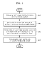
- FIG. 1 is a flowchart of a method of displaying a plurality of different images of an object according to an embodiment.
- a method of displaying a plurality of different images may include: displaying a first image produced with respect to an object S100; selecting at least one ROI from the displayed first image obtained therefrom S200; producing at least one second image of different type with respect to the selected at least one ROI S300; and displaying the first image and at least one second image S400.
- displaying a first image produced with respect to an object S100 selecting at least one ROI from the displayed first image obtained therefrom S200; producing at least one second image of different type with respect to the selected at least one ROI S300; and displaying the first image and at least one second image S400.
- the first image according to an embodiment of the present invention may include a B mode image and the second image may include a functional image or a parametric image of the object.
- the functional image or the parametric image according to an embodiment of the present invention may include a color flow image, a shear modulus image, an attenuation image, an effective scatterer size map image, and a sound velocity map image.
- the color flow image according to an embodiment of the present invention may include an image in which a frequency shift of a radio frequency (RF) echo reflected from a pulse of ultrasound irradiated to the object is used to calculate a velocity of a moving object, and calculation results obtained therefrom are expressed in predetermined colors.
- RF radio frequency
- the shear modulus image may include an image expressed by using acoustic force that is relatively and strongly focused to generate a shear wave in tissue of the object and calculating a velocity of movements of the shear wave generated therefrom in the object to calculate a shear modulus of the object.
- the attenuation image may include an image generated based on the attenuation coefficients calculated using variations of RF echoes over a depth , knowing backscattering properties in the ROI of the object beforehand or assuming that the same does not change in the ROI.
- the variations in the RF echo signal may be determined by analyzing changes in a frequency or a magnitude of the RF echo signal.
- the effective scatterer size map image when the attenuation of the RF echo signal is compensated for, an inherent backscattering (a signal at an angle of 180° received from an object) function of the ROI may be obtained, and the effective scatterer size map image may include an image that displays sizes of effective scatterer obtained using a form factor that determines a shape of a scatterer.
- the size of the scatterer obtained therefrom may not an actual physical size and thus, it may be referred to as the effective scatterer size.
- the sound velocity map image may include an image showing sound velocity obtained on the basis of the fact that an image is well-focused and looks clear when the sound velocity used in the beamformer of the ultrasound apparatus matches that of the object.
- the second image may include a functional image or a parametric image produced beforehand and stored in a storage unit (not shown), of the object.
- the second image may include the functional image or the parametric image produced beforehand and stored in the storage unit (not shown), of the object, and a functional image or a parametric image produced during current diagnosis.
- the type of the second image may be preset or determined in real-time based on a frequency of use of each image, reliability of each image during diagnosis of a lesion , or external input.
- an image showing at least one of attenuation, sound velocity, shear wave velocity, and power doppler may be used in addition to the B mode image to aid in diagnosing a lesion within the breast in a fast and precise manner.
- comparing and analyzing plurality of the attenuation image, the sound velocity image, the shear wave velocity image, and the power doppler image by simultaneously displaying the same may help to determine the malignancy of the mass within the breast in a fast and precise manner.
- the second image may have a varying frequency of use for each type of image depending on the type of examination (for example, cardiac function diagnosis, abdominal diagnosis, and fetal diagnosis) and thus, an image having high frequency of use may be produced with a high priority.
- the shear wave velocity image may have high frequency of use.
- the apparatus may be preset to generate a shear wave velocity image.
- the user may enter the type of the second image that will be generated by using an external input, such that the second image may be modified in real-time through addition or deletion, depending on the type of image to be used.
- the type of the second image to be produced may be determined based on the reliability of that image in diagnosis of a lesion. For example, in case of a breast mass, at least one image of an attenuation image, a sound velocity image, a shear wave velocity image, and a power doppler image, which are believed to have useful diagnostic values, may be set to be produced beforehand or in real-time.
- a sequence of displaying at least one second image to be displayed with the first image may be preset or determined in real-time based on a frequency of use of each image, reliability during the diagnosis of a lesion, or an external input.
- the shear wave velocity image may be utilized frequently thus, the shear wave velocity image may not only be generated during the diagnosis of a tumor in the breast, but also the generated shear wave velocity image may be displayed before another type of the second image (for example, a power doppler image or the like).
- a display sequence of the second image may be determined based on the reliability during the diagnosis of a lesion, and for example, for a breast examination, the second image may be displayed in a sequence of the shear wave velocity image, the power doppler image, the attenuation image, and the sound velocity image.
- sequence for displaying the second image may be changed according to the external input entered by the user.
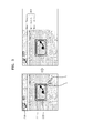
- FIGS. 2A and 2B show a display of a plurality of different images of an object according to an embodiment.
- a first image 210 generated with respect to the object may be displayed S100.
- the first image 210 may be a B mode image.
- At least one ROI 220 may be selected in the displayed first image 210 S200.
- the ROI 220 may be a predetermined region selected according to an external input or selected to have a predetermined area by the user.
- the ROI 220 may be automatically generated according to a predetermined area including a boundary at which brightness changes abruptly in the first image 210 (for example, lesion or the like).
- a second image set 230 including at least one type of second image may be generated S300.
- the second image set 230 may be a set in which at least one of the produced second image is either simplified or reduced, or an identifier (includes letters, numbers, and icons) is set representing the second image.
- an icon representing a power doppler image (PDI) may be generated as the second image set 230.
- the second image may be a functional image or a parametric image.
- the second image may include the attenuation image, the sound velocity image, the shear wave velocity image, and the PDI.
- the first image 210 and the second image set 230 may be displayed S400.
- displaying the first image and at least one second image of the second image set 230 S400 may further include overlaying a second image selected according to an external input for selecting a second image from the second image set on the ROI to display.
- at least one image 231 may be selected from the produced second image set 230, such that the selected image 231 may be overlaid on the ROI 220 for a display 221.
- displaying the first image 210 and at least one second image S400 may further include displaying the second image next to the first image 210 in parallel.
- the second image selected according to the external input for selecting the second image 231 from the second image set 230 may be displayed 240 in parallel next to the first image 210.
- the expression, "displayed in parallel” may refer to a display in a predetermined direction.
- the expression, "predetermined direction” may include at least one of up, down, left, right, and diagonal directions.
- the second image selected according to the external input for selecting a second image 235 from the second image set 230 may be displayed 250 next to the first image 210 to be displayed in parallel 250.
- Each of the selected second images 231 or 235 may be displayed 240 and 250 in a predetermined direction.
- the predetermined direction may include at least one of up, down, left, right, and diagonal directions.
- the second image may be displayed according to a sequence of display that is determined as described above.
- the sequence of the shear wave velocity image, the PDI, the attenuation image, and the sound velocity image which is in the order of high degree of association to the breast examination, may be, for example, sequentially displayed from the top (or left) to the bottom (or down) of a display unit.
- FIG. 3 shows a display of diagnosis values of the object according to an embodiment.
- the method may further include selecting at least one ROI from the displayed second image, extracting a predetermined diagnosis value from a selected sub-ROI, and displaying an extracted diagnosis value obtained therefrom.
- At least one sub-ROI 222 may be selected from the second image that is displayed 221 to overlap the ROI 220.
- the sub-ROI 222 may have the same area in the same location as the ROI 220 of the first image or may be selected to have a smaller area than that of the ROI 220.
- a predetermined diagnosis value may be extracted from data showing an image included in the selected sub-ROI 222.
- the diagnosis value may include an average value, a median value, a standard deviation value, a minimum value, or a maximum value of a sound velocity, shear modulus, attenuation coefficient, and the like of movement of tissue or blood flow.
- the extracted diagnosis value may be displayed through a display unit.
- the average value, the minimum value, and the maximum value of velocities of the movements of tissues or blood flow may be displayed as a diagnosis value 260. Accordingly, the user may determine the presence/absence of abnormalities in the object or the seriousness of a disease based on the diagnosis value provided.
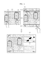
- FIG. 4 shows a display of at least one type of image (with respect to a plurality of selected ROIs according to an embodiment of the present invention.
- a type of a second image produced with respect to the first ROI and a type of a second image produced with respect to the second ROI may be the same or different.
- the type of the second image included in second image sets 410 and 420 produced for each ROI 401 or 402 may be the same or different.
- a PDI a shear wave velocity image
- an attenuation image a sound velocity image
- a PDI, a shear wave velocity image, and an attenuation image may be included in the second image set 410 produced in correspondence to the first ROI 401, but only a PDI, an attenuation image, and a sound velocity image may be included in the second image set 420 produced in correspondence to the second ROI 402.
- a second image 411 selected in the second image set 410 produced in correspondence to the first ROI 401 may be disposed next to the first image 210 to be displayed 430 in parallel. Also, as shown in FIG. 2A , the image selected in the second image set 410 produced in correspondence to the first ROI 401 may overlap the first ROI 401 for a display. Likewise, a second image 425 selected in the second image set 420 produced in correspondence to the second ROI 402 may be disposed next to the first image 210 in parallel for a display 440. Also, as shown in FIG. 2A , the second image 425 selected in the second image set 420 produced in correspondence to the second ROI 402 may overlap the second ROI 402 for a display.
- FIG. 5 is a block diagram of an apparatus 500 for displaying a plurality of different images of an object, according to an embodiment.
- the apparatus 500 for displaying a plurality of different images of an object, the apparatus 500 including: an image producing unit 510 producing a first image of the object, a display unit 520 displaying the first image produced therefrom, and a ROI selection unit 530 selecting at least one ROI selected from at least one first image displayed therefrom.
- the apparatus 500 may include an external input receiving unit 540 for receiving an external input. At least one of different types of the second image with respect to the selected ROI may be produced by the image producing unit 510. The first image and at least one second image may be displayed by the display unit 520.
- the first image includes a B mode image and the second image may include a functional image or parametric image of the object.
- a type of the second image may be preset or determined in real-time based on a frequency of use of each image, the reliability of each image in diagnosis of a lesion, or an external input.
- a sequence of display of at least one second image to be displayed with the first image may be preset or determined in real-time based on a frequency of use of each image, the reliability in diagnosis of a lesion of each image, or an external input.
- the display unit 52 may overlay the second image on the ROI according to an external input received through the external input receiving unit 540 to display the same or dispose the second image near the first image in parallel.
- FIG. 6 is a block diagram of an apparatus 500 for displaying a plurality of different images of an object further including a diagnosis value extraction unit 550, according to an embodiment.
- the apparatus 500 may further include the diagnosis value extraction unit 550 extracting a predetermined diagnosis value from a sub-ROI selected when at least one sub-ROI is selected in a displayed second image by a ROI selection unit 530.
- the extracted diagnosis value may be displayed by the display unit 520.
- a type of the second image produced for the first ROI and a type of the second ROI produced for the second ROI may be the same or different.
- embodiments of the present invention can also be implemented through computer-readable code/instructions in/on a medium, e.g., a computer-readable medium, to control at least one processing element to implement any above-described embodiment.
- a medium e.g., a computer-readable medium
- the medium can correspond to any medium/media permitting the storage and/or transmission of the computer-readable code.
- the computer-readable code can be recorded/transferred on a medium in a variety of ways, with examples of the medium including recording media, such as magnetic storage media (e.g., ROM, floppy disks, hard disks, etc.) and optical recording media (e.g., CD-ROMs, DVDs, etc.), and transmission media such as Internet transmission media.
- the medium may be such a defined and measurable structure including or carrying a signal or information, such as a device carrying a bitstream according to one or more embodiments of the present invention.
- the media may also be a distributed network, so that the computer-readable code is stored/transferred and executed in a distributed fashion.
- the processing element could include a processor or a computer processor, and processing elements may be distributed and/or included in a single device.
Landscapes
- Engineering & Computer Science (AREA)
- Health & Medical Sciences (AREA)
- Life Sciences & Earth Sciences (AREA)
- Physics & Mathematics (AREA)
- General Physics & Mathematics (AREA)
- Radiology & Medical Imaging (AREA)
- General Health & Medical Sciences (AREA)
- Nuclear Medicine, Radiotherapy & Molecular Imaging (AREA)
- Biomedical Technology (AREA)
- Heart & Thoracic Surgery (AREA)
- Medical Informatics (AREA)
- Molecular Biology (AREA)
- Surgery (AREA)
- Animal Behavior & Ethology (AREA)
- Pathology (AREA)
- Public Health (AREA)
- Veterinary Medicine (AREA)
- Biophysics (AREA)
- Theoretical Computer Science (AREA)
- Computer Networks & Wireless Communication (AREA)
- Radar, Positioning & Navigation (AREA)
- Remote Sensing (AREA)
- Computer Hardware Design (AREA)
- Multimedia (AREA)
- Ultra Sonic Daignosis Equipment (AREA)
Abstract
Description
- This application claims the benefit of Korean Patent Application No.
10-2014-0029269 filed on March 12, 2014 - One or more embodiments of the present invention relate to a method and apparatus for displaying a plurality of different images of an object, and more particularly to a method and apparatus for displaying different images by producing at least one type of image that is related to a selected region of interest of a first image of the object.
- An ultrasound diagnostic apparatus transmits an ultrasound signal to a predetermined portion of a body, uses reflected ultrasound signal from tissues of the body to obtain images related to layers of soft tissues and blood flow.
- In other words, the ultrasound diagnostic apparatus irradiates ultrasound signals generated from a transducer to an object and receives echo signals reflected from the object to obtain images related to internal areas of the object. The ultrasound diagnostic apparatus is advantageous in that information about the object may be displayed in real time. Also, the ultrasound diagnostic apparatus is considered to be safe because there is no X-ray exposure or the like and thus, the ultrasound diagnostic apparatus is widely used with another image diagnostic apparatus such as an X-ray diagnostic device, a computerized tomography scanner, a magnetic resonance image (MRI) apparatus, and a nuclear medicine diagnostic apparatus.
- One or more embodiments of the present invention include a method of displaying a plurality of different images of an object.
- Additional aspects will be set forth in part in the description which follows and, in part, will be apparent from the description, or may be learned by practice of the presented embodiments.
- According to one or more embodiments of the present invention, provided is a method of displaying a plurality of different images of an object, the method including: displaying a first image produced with respect to the object;
- selecting at least one region of interest from the displayed first image obtained therefrom;
- producing at least one second image of a type different from a type of the first image, with respect to a selected region of interest; and
- displaying the first image and the produced at least one second image.
- The first image may include a B mode image, and the at least one second image comprises a functional image or a parametric image of the object.
- A type of the at least one second image may be preset or determined in real-time based on a frequency of use of each image, reliability of each image during a diagnosis of a lesion , or an external input.
- A sequence of displaying the at least one second image with the first image may be preset or determined in real-time based on a frequency of use of each image, reliability of each image during the diagnosis of a lesion, or an external input.
- The displaying the first image and the at least one second image may further include overlaying the at least one second image on the region of interest according to an external input to display the same or dispose the second image near the first image to be displayed in parallel.
- The method may further include:
- selecting at least one sub-region of interest from the displayed at least one second image,
- extracting a predetermined diagnosis value from a selected sub-region of interest obtained therefrom, and
- displaying an extracted value obtained therefrom.
- When a plurality of regions of interest comprising a first region of interest and a second region of interest in the first image are selected, a type of a second image produced with respect to the first ROI and a type of a second image produced with respect to the second ROI may be the same or different
- An apparatus for displaying a plurality of different images of an object, the apparatus including:
- an image producing unit producing a first image of the object,
- a display unit displaying the first image produced therefrom, and
- a region of interest selection unit selecting at least one region of interest selected from at least one first image displayed therefrom, wherein
- at least one second image of a type different from a type of the first image, with respect to the selected region of interest is produced by the image producing unit, and
- the first image and the at least two different types of second images are displayed by the display unit.
- The first image may include a B mode image and the second image may include a functional image or a parametric image of the object.
- A type of the second image may be preset or determined in real-time based on a frequency of use of each image, reliability of each image in diagnosis of a lesion, or an external input.
- A sequence of display of at least one second image to be displayed with the first image may be preset or determined in real-time based on a frequency of use of each image, reliability of each image in diagnosis of a lesion, or an external input.
- The display unit may overlay the second image on the region of interest according to an external input to display the same or dispose the second image near the first image in parallel.
- The apparatus may further include a diagnosis value extraction unit extracting a predetermined diagnosis value from a selected sub-region of interest when at least one sub-region of interest is selected in a displayed second image by a region of interest selection unit, wherein
- the diagnosis value extracted by the display unit is displayed.
- When a plurality of regions of interest including the first region of interest and the second region of interest are selected in the first image, a type of a second image produced for the first region of interest and a type of a second image produced for the second region of interest may be the same or different.
- Meanwhile, as an embodiment of the present invention, provided is a computer-readable recording medium, wherein a program for processing any of the program is recorded.
- These and/or other aspects will become apparent and more readily appreciated from the following description of the embodiments, taken in conjunction with the accompanying drawings in which:
-
FIG. 1 is a flowchart of a method of displaying a plurality of different images of an object, according to an embodiment of the present invention; -
FIG. 2A and2B show a display of a plurality of different images of an object according to an embodiment of the present invention; -
FIG. 3 shows a display of diagnosis values of an object according to an embodiment; -
FIG. 4 shows a display of at least one type of image with respect to a plurality of selected regions of interest according to an embodiment of the present invention; -
FIG. 5 is a block diagram of an apparatus displaying a plurality of different images of an object according to an embodiment of the present invention; and -
FIG. 6 is a block diagram of an apparatus displaying a plurality of different images of an object further including a diagnosis value extraction unit according to an embodiment of the present invention. - Reference will now be made in detail to embodiments, examples of which are illustrated in the accompanying drawings, wherein like reference numerals refer to like elements throughout. In this regard, the present embodiments may have different forms and should not be construed as being limited to the descriptions set forth herein. Accordingly, the embodiments are merely described below, by referring to the figures, to explain aspects of the present description. Expressions such as "at least one of," when preceding a list of elements, modify the entire list of elements and do not modify the individual elements of the list.
- Terms as used herein will be briefly described and the present invention will be described in greater detail.
- The terms as used herein are general terms that are currently being used widely in consideration of functions of the present invention, but the terms may vary depending on the intention of a person in the art or precedents, and the appearance of new technology. Also, in certain cases, an applicant may have randomly selected the terms, in which case, the definitions thereof will be described in detail in the detailed description of the invention. Accordingly, the terms used herein should be defined based on the definitions of the terms and the entirety of the present invention, instead of simple names of the terms.
- Throughout the specification, when a portion "includes" a component, another element may be further included, rather than excluding the existence of the other element, unless otherwise described. Also, throughout the specification, terms such as "...portion" or "module" refers to a unit for processing at least one function or operation, which may be achieved through hardware, software, or a combination of hardware and software.
- Throughout the specification, the expression "ultrasound image" refers to an image of an object obtained by using ultrasound.
- The term "object" may refer to a portion of a body. For example, the object may include an organ such as a liver, a heart, a uterus, a brain, a breast, and an abdomen, or a fetus. Also, the object may include a phantom, wherein the phantom may refer to a material that mimics density and acoustic characteristics of human or animal tissues, such as sound velocity and attenuation.
- Also, throughout the specification, the term "user" may be a medical professional such as a doctor, a nurse, a medical technologist, a medical imaging specialist, or the like, or a technologist for repairing medical apparatuses, but the medical professional is not limited thereto.
- According to conventional technology, different types of images, such as attenuation, sound velocity, shear wave velocity, shear modulus, power doppler, and 3D volume images, are processed and generated through different modes to obtain the images and thus, a mutual comparison thereof is not easy.
- In contrast, according to an embodiment of the present invention, all functional images and parametric images may be generated and then displayed, which may be obtained through one scanning of a region of interest of an object without changing the location of a probe. Also, according to an embodiment of the present invention, a diagnosis value of the region of interest may be extracted and displayed to increase a diagnostic efficiency of an ultrasound apparatus for the user. In other words, according to an embodiment of the present invention, a plurality of different types of images with respect to the region of interest of an object may be displayed and thus, the user may use the displayed plurality of different types of displayed images to perform an overall diagnosis of the region of interest in a fast and precise manner.
- According to an embodiment of the present invention, a parameter that may be obtained in different modes of the same area of the object (for example, the region of interest (ROI)) may be provided to enable an overall comparison and analysis of the ROI of the object. Also, a B mode image is obtained with priority and then images in various other modes may be obtained based on the ROI selected from the B mode image to simultaneously obtain and display various types of images used for diagnosis.
-
FIG. 1 is a flowchart of a method of displaying a plurality of different images of an object according to an embodiment. - According to an embodiment of the present invention, a method of displaying a plurality of different images (of the object may include: displaying a first image produced with respect to an object S100; selecting at least one ROI from the displayed first image obtained therefrom S200; producing at least one second image of different type with respect to the selected at least one ROI S300; and displaying the first image and at least one second image S400. Each process will be described with reference to
FIGS 2A and2B . - The first image according to an embodiment of the present invention may include a B mode image and the second image may include a functional image or a parametric image of the object. The functional image or the parametric image according to an embodiment of the present invention may include a color flow image, a shear modulus image, an attenuation image, an effective scatterer size map image, and a sound velocity map image.
- The color flow image according to an embodiment of the present invention may include an image in which a frequency shift of a radio frequency (RF) echo reflected from a pulse of ultrasound irradiated to the object is used to calculate a velocity of a moving object, and calculation results obtained therefrom are expressed in predetermined colors.
- Also, the shear modulus image may include an image expressed by using acoustic force that is relatively and strongly focused to generate a shear wave in tissue of the object and calculating a velocity of movements of the shear wave generated therefrom in the object to calculate a shear modulus of the object.
- Also, the attenuation image may include an image generated based on the attenuation coefficients calculated using variations of RF echoes over a depth , knowing backscattering properties in the ROI of the object beforehand or assuming that the same does not change in the ROI. The variations in the RF echo signal may be determined by analyzing changes in a frequency or a magnitude of the RF echo signal.
- Also, regarding the effective scatterer size map image, when the attenuation of the RF echo signal is compensated for, an inherent backscattering (a signal at an angle of 180° received from an object) function of the ROI may be obtained, and the effective scatterer size map image may include an image that displays sizes of effective scatterer obtained using a form factor that determines a shape of a scatterer. The size of the scatterer obtained therefrom may not an actual physical size and thus, it may be referred to as the effective scatterer size.
- Also, the sound velocity map image may include an image showing sound velocity obtained on the basis of the fact that an image is well-focused and looks clear when the sound velocity used in the beamformer of the ultrasound apparatus matches that of the object.
- Also, according to another embodiment of the present invention, the second image may include a functional image or a parametric image produced beforehand and stored in a storage unit (not shown), of the object. For example, when pre-acquired images are compared for tracing expression results of a lesion, the second image may include the functional image or the parametric image produced beforehand and stored in the storage unit (not shown), of the object, and a functional image or a parametric image produced during current diagnosis.
- According to an embodiment of the present invention, the type of the second image may be preset or determined in real-time based on a frequency of use of each image, reliability of each image during diagnosis of a lesion , or external input. For example, when the object is breast, an image showing at least one of attenuation, sound velocity, shear wave velocity, and power doppler may be used in addition to the B mode image to aid in diagnosing a lesion within the breast in a fast and precise manner. In other words, comparing and analyzing plurality of the attenuation image, the sound velocity image, the shear wave velocity image, and the power doppler image by simultaneously displaying the same may help to determine the malignancy of the mass within the breast in a fast and precise manner.
- The second image may have a varying frequency of use for each type of image depending on the type of examination (for example, cardiac function diagnosis, abdominal diagnosis, and fetal diagnosis) and thus, an image having high frequency of use may be produced with a high priority. For example, to determine the presence or absence of tumor in a breast, the shear wave velocity image may have high frequency of use. Accordingly, when determining the malignancy of a tumor within a breast, the apparatus may be preset to generate a shear wave velocity image. Also, to diagnose a lesion in the object, the user may enter the type of the second image that will be generated by using an external input, such that the second image may be modified in real-time through addition or deletion, depending on the type of image to be used.
- Also, when the object is a breast as described above, the type of the second image to be produced may be determined based on the reliability of that image in diagnosis of a lesion. For example, in case of a breast mass, at least one image of an attenuation image, a sound velocity image, a shear wave velocity image, and a power doppler image, which are believed to have useful diagnostic values, may be set to be produced beforehand or in real-time.
- Also, according to an embodiment of the present invention, a sequence of displaying at least one second image to be displayed with the first image may be preset or determined in real-time based on a frequency of use of each image, reliability during the diagnosis of a lesion, or an external input.
- As described above, to determine the malignancy of a tumor in the breast, the shear wave velocity image may be utilized frequently thus, the shear wave velocity image may not only be generated during the diagnosis of a tumor in the breast, but also the generated shear wave velocity image may be displayed before another type of the second image (for example, a power doppler image or the like).
- Also, a display sequence of the second image may be determined based on the reliability during the diagnosis of a lesion, and for example, for a breast examination, the second image may be displayed in a sequence of the shear wave velocity image, the power doppler image, the attenuation image, and the sound velocity image.
- Also, the sequence for displaying the second image may be changed according to the external input entered by the user.
-
FIGS. 2A and2B show a display of a plurality of different images of an object according to an embodiment. - Referring to
FIG. 1 and according to an embodiment, afirst image 210 generated with respect to the object may be displayed S100. As described above, thefirst image 210 may be a B mode image. - Also, at least one
ROI 220 may be selected in the displayedfirst image 210 S200. TheROI 220 may be a predetermined region selected according to an external input or selected to have a predetermined area by the user. Also, theROI 220 may be automatically generated according to a predetermined area including a boundary at which brightness changes abruptly in the first image 210 (for example, lesion or the like). - According to an embodiment of the present invention, with respect to the
ROI 220, a second image set 230 including at least one type of second image may be generated S300. Also, the second image set 230 may be a set in which at least one of the produced second image is either simplified or reduced, or an identifier (includes letters, numbers, and icons) is set representing the second image. For example, an icon representing a power doppler image (PDI) may be generated as the second image set 230. - As described above, the second image may be a functional image or a parametric image. For example, the second image may include the attenuation image, the sound velocity image, the shear wave velocity image, and the PDI.
- According to an embodiment, the
first image 210 and the second image set 230 may be displayed S400. According to an embodiment, displaying the first image and at least one second image of the second image set 230 S400 may further include overlaying a second image selected according to an external input for selecting a second image from the second image set on the ROI to display. In other words, as shown inFIG. 2A , at least oneimage 231 may be selected from the produced second image set 230, such that the selectedimage 231 may be overlaid on theROI 220 for adisplay 221. - Also, according to an embodiment of the present invention, displaying the
first image 210 and at least one second image S400 may further include displaying the second image next to thefirst image 210 in parallel. As shown inFIG. 2B , the second image selected according to the external input for selecting thesecond image 231 from the second image set 230 may be displayed 240 in parallel next to thefirst image 210. The expression, "displayed in parallel" may refer to a display in a predetermined direction. The expression, "predetermined direction" may include at least one of up, down, left, right, and diagonal directions. - Also, the second image selected according to the external input for selecting a
second image 235 from the second image set 230 may be displayed 250 next to thefirst image 210 to be displayed in parallel 250. Each of the selectedsecond images - Also, according to an embodiment of the present invention, the second image may be displayed according to a sequence of display that is determined as described above. For example, in the description above, the sequence of the shear wave velocity image, the PDI, the attenuation image, and the sound velocity image, which is in the order of high degree of association to the breast examination, may be, for example, sequentially displayed from the top (or left) to the bottom (or down) of a display unit.
-
FIG. 3 shows a display of diagnosis values of the object according to an embodiment. - According to an embodiment of the present invention, the method may further include selecting at least one ROI from the displayed second image, extracting a predetermined diagnosis value from a selected sub-ROI, and displaying an extracted diagnosis value obtained therefrom.
- Referring to
FIGS. 2A and3 , at least one sub-ROI 222 may be selected from the second image that is displayed 221 to overlap theROI 220. The sub-ROI 222 may have the same area in the same location as theROI 220 of the first image or may be selected to have a smaller area than that of theROI 220. - A predetermined diagnosis value may be extracted from data showing an image included in the selected
sub-ROI 222. For example, the diagnosis value may include an average value, a median value, a standard deviation value, a minimum value, or a maximum value of a sound velocity, shear modulus, attenuation coefficient, and the like of movement of tissue or blood flow. - The extracted diagnosis value may be displayed through a display unit. For example, as shown in
FIG. 3 , the average value, the minimum value, and the maximum value of velocities of the movements of tissues or blood flow may be displayed as adiagnosis value 260. Accordingly, the user may determine the presence/absence of abnormalities in the object or the seriousness of a disease based on the diagnosis value provided. -
FIG. 4 shows a display of at least one type of image (with respect to a plurality of selected ROIs according to an embodiment of the present invention. - According to an embodiment of the present invention, when the plurality of ROIs, including a first ROI and a second ROI in a first image, are selected, a type of a second image produced with respect to the first ROI and a type of a second image produced with respect to the second ROI may be the same or different.
- For example, as illustrated in
FIG. 4 , when thefirst ROI 401 and thesecond ROI 402 are selected, the type of the second image included in second image sets 410 and 420 produced for eachROI first ROI 401 and the second image set 420 produced in correspondence to thesecond ROI 402. Also, a PDI, a shear wave velocity image, and an attenuation image may be included in the second image set 410 produced in correspondence to thefirst ROI 401, but only a PDI, an attenuation image, and a sound velocity image may be included in the second image set 420 produced in correspondence to thesecond ROI 402. - Referring to
FIG. 2B andFIG. 4 , asecond image 411 selected in the second image set 410 produced in correspondence to thefirst ROI 401 may be disposed next to thefirst image 210 to be displayed 430 in parallel. Also, as shown inFIG. 2A , the image selected in the second image set 410 produced in correspondence to thefirst ROI 401 may overlap thefirst ROI 401 for a display. Likewise, asecond image 425 selected in the second image set 420 produced in correspondence to thesecond ROI 402 may be disposed next to thefirst image 210 in parallel for adisplay 440. Also, as shown inFIG. 2A , thesecond image 425 selected in the second image set 420 produced in correspondence to thesecond ROI 402 may overlap thesecond ROI 402 for a display. -
FIG. 5 is a block diagram of anapparatus 500 for displaying a plurality of different images of an object, according to an embodiment. - According to an embodiment of the present invention, provided is the
apparatus 500 for displaying a plurality of different images of an object, theapparatus 500 including: animage producing unit 510 producing a first image of the object, adisplay unit 520 displaying the first image produced therefrom, and aROI selection unit 530 selecting at least one ROI selected from at least one first image displayed therefrom. Also, theapparatus 500 according to an embodiment of the present invention may include an externalinput receiving unit 540 for receiving an external input. At least one of different types of the second image with respect to the selected ROI may be produced by theimage producing unit 510. The first image and at least one second image may be displayed by thedisplay unit 520. - The first image includes a B mode image and the second image may include a functional image or parametric image of the object.
- A type of the second image may be preset or determined in real-time based on a frequency of use of each image, the reliability of each image in diagnosis of a lesion, or an external input.
- A sequence of display of at least one second image to be displayed with the first image may be preset or determined in real-time based on a frequency of use of each image, the reliability in diagnosis of a lesion of each image, or an external input.
- The display unit 52 may overlay the second image on the ROI according to an external input received through the external
input receiving unit 540 to display the same or dispose the second image near the first image in parallel. -
FIG. 6 is a block diagram of anapparatus 500 for displaying a plurality of different images of an object further including a diagnosisvalue extraction unit 550, according to an embodiment. - The
apparatus 500 according to an embodiment of the present invention may further include the diagnosisvalue extraction unit 550 extracting a predetermined diagnosis value from a sub-ROI selected when at least one sub-ROI is selected in a displayed second image by aROI selection unit 530. The extracted diagnosis value may be displayed by thedisplay unit 520. - Also, when a plurality of ROIs including the first ROI and the second ROI are selected in the first image, a type of the second image produced for the first ROI and a type of the second ROI produced for the second ROI may be the same or different.
- Descriptions about the method above may apply to the
apparatus 500 and thus are not repeatedly provided - In addition, other embodiments of the present invention can also be implemented through computer-readable code/instructions in/on a medium, e.g., a computer-readable medium, to control at least one processing element to implement any above-described embodiment. The medium can correspond to any medium/media permitting the storage and/or transmission of the computer-readable code.
- The computer-readable code can be recorded/transferred on a medium in a variety of ways, with examples of the medium including recording media, such as magnetic storage media (e.g., ROM, floppy disks, hard disks, etc.) and optical recording media (e.g., CD-ROMs, DVDs, etc.), and transmission media such as Internet transmission media. Thus, the medium may be such a defined and measurable structure including or carrying a signal or information, such as a device carrying a bitstream according to one or more embodiments of the present invention. The media may also be a distributed network, so that the computer-readable code is stored/transferred and executed in a distributed fashion. Furthermore, the processing element could include a processor or a computer processor, and processing elements may be distributed and/or included in a single device.
- It should be understood that the exemplary embodiments described therein should be considered in a descriptive sense only and not for purposes of limitation. Descriptions of features or aspects within each embodiment should typically be considered as available for other similar features or aspects in other embodiments.
- While one or more embodiments of the present invention have been described with reference to the figures, it will be understood by those of ordinary skill in the art that various changes in form and details may be made therein without departing from the spirit and scope of the present invention as defined by the following claims.
Claims (15)
- A method of displaying a plurality of different images of an object, the method comprising:displaying a first image produced with respect to the object;selecting at least one region of interest from the displayed first image obtained therefrom;producing at least one second image of a type different from a type of the first image, with respect to a selected region of interest; anddisplaying the first image and the produced at least one second image.
- The method of claim 1, wherein
the first image comprises a B mode image, and
the at least one second image comprises a functional image or a parametric image of the object. - The method of claim 1, wherein a type of the at least one second image is preset or determined in real-time based on a frequency of use of each image, reliability during a diagnosis of a lesion for each image, or an external input.
- The method of claim 1, wherein a sequence of displaying the at least one second image to be displayed with the first image is preset or determined in real-time based on a frequency of use of each image, reliability of each image during the diagnosis of a lesion , or an external input.
- The method of claim 1, wherein displaying the first image and the at least one second image further comprises overlaying the at least one second image on the region of interest according to an external input to display the same or dispose the second image near the first image to be displayed in parallel.
- The method of claim 1, wherein the method further comprises:selecting at least one sub-region of interest from the displayed at least one second image,extracting a predetermined diagnosis value from a selected sub-region of interest obtained therefrom, anddisplaying an extracted value obtained therefrom.
- The method of claim 1, wherein when a plurality of regions of interest comprising a first region of interest and a second region of interest in the first image are selected, a type of a second image produced with respect to the first ROI and a type of a second image produced with respect to the second ROI are the same or different.
- An apparatus for displaying a plurality of different images of an object, the apparatus comprising:an image producing unit producing a first image of the object,a display unit displaying the first image produced therefrom, anda region of interest selection unit selecting at least one region of interest selected from at least one first image displayed therefrom, whereinat least one second image of a type different from a type of the first image, with respect to the selected region of interest is produced by the image producing unit, andthe first image and the at least two different types of second images are displayed by the display unit.
- The apparatus of claim 8, wherein the first image comprises a B mode image and the second image comprises a functional image or a parametric image of the object.
- The apparatus of claim 8, wherein a type of the second image is preset or determined in real-time based on a frequency of use of each image, reliability of each image in diagnosis of a lesion, or an external input.
- The apparatus of claim 8, wherein a sequence of display of at least one second image to be displayed with the first image is preset or determined in real-time based on a frequency of use of each image, reliability of each image in diagnosis of a lesion, or an external input.
- The apparatus of claim 8, wherein the display unit overlays the second image on the region of interest according to an external input to display the same or dispose the second image near the first image in parallel.
- The apparatus of claim 8, the apparatus further comprising a diagnosis value extraction unit extracting a predetermined diagnosis value from a selected sub-region of interest when at least one sub-region of interest is selected in a displayed second image by a region of interest selection unit, wherein the diagnosis value extracted is displayed by the display unit.
- The apparatus of claim 8, wherein when a plurality of regions of interest comprising the first region of interest and the second region of interest are selected in the first image, a type of a second image produced for the first region of interest and a type of a second image produced for the second region of interest are the same or different.
- A computer-readable recording medium, wherein a program for processing any one method of claims 1 to 7 is recorded.
Applications Claiming Priority (1)
| Application Number | Priority Date | Filing Date | Title |
|---|---|---|---|
| KR1020140029269A KR102268668B1 (en) | 2014-03-12 | 2014-03-12 | The method and apparatus for displaying a plurality of different images of an object |
Publications (2)
| Publication Number | Publication Date |
|---|---|
| EP2919033A1 true EP2919033A1 (en) | 2015-09-16 |
| EP2919033B1 EP2919033B1 (en) | 2019-08-21 |
Family
ID=51485465
Family Applications (1)
| Application Number | Title | Priority Date | Filing Date |
|---|---|---|---|
| EP14182595.0A Active EP2919033B1 (en) | 2014-03-12 | 2014-08-28 | Method and apparatus for displaying a plurality of different images of an object |
Country Status (4)
| Country | Link |
|---|---|
| US (1) | US9489921B2 (en) |
| EP (1) | EP2919033B1 (en) |
| KR (1) | KR102268668B1 (en) |
| CN (1) | CN104905812B (en) |
Families Citing this family (14)
| Publication number | Priority date | Publication date | Assignee | Title |
|---|---|---|---|---|
| KR20170067444A (en) * | 2015-12-08 | 2017-06-16 | 삼성메디슨 주식회사 | Ultrasound diagnostic apparatus and control method for the same |
| WO2017138459A1 (en) * | 2016-02-08 | 2017-08-17 | 富士フイルム株式会社 | Acoustic wave image generation device and acoustic wave image generation method |
| JP6663027B2 (en) | 2016-09-12 | 2020-03-11 | 富士フイルム株式会社 | Ultrasound diagnostic system and control method of the ultrasound diagnostic system |
| KR102561305B1 (en) * | 2016-11-03 | 2023-07-31 | 한화비전 주식회사 | Apparatus for Providing Image and Method Thereof |
| KR102655299B1 (en) * | 2016-11-15 | 2024-04-08 | 삼성메디슨 주식회사 | Ultrasound probe and manufacturing method for the same |
| KR102589628B1 (en) | 2016-12-13 | 2023-10-13 | 로비 가이드스, 인크. | System and method for minimizing occlusion of media assets by overlays by predicting the movement path of objects of interest in media assets and avoiding placing overlays on the movement path |
| US10799219B2 (en) | 2017-04-28 | 2020-10-13 | General Electric Company | Ultrasound imaging system and method for displaying an acquisition quality level |
| CN107728892B (en) * | 2017-09-20 | 2020-09-25 | 平安科技(深圳)有限公司 | Picture display method, device, terminal and storage medium |
| KR101898580B1 (en) * | 2018-01-22 | 2018-09-13 | 주식회사 뷰노 | Method for facilitating image view and apparatus using the same |
| CN109286824B (en) * | 2018-09-28 | 2021-01-01 | 武汉斗鱼网络科技有限公司 | Live broadcast user side control method, device, equipment and medium |
| CN110604598B (en) * | 2018-12-04 | 2021-01-15 | 深圳迈瑞生物医疗电子股份有限公司 | Ultrasonic imaging method and ultrasonic imaging system |
| US11850099B2 (en) * | 2019-02-26 | 2023-12-26 | Canon Medical Systems Corporation | Ultrasonic diagnostic apparatus |
| CN112438751B (en) * | 2019-09-04 | 2024-11-08 | 通用电气精准医疗有限责任公司 | Method and system for shear wave elastography and medium storing corresponding program |
| JP7242623B2 (en) * | 2020-11-27 | 2023-03-20 | ジーイー・プレシジョン・ヘルスケア・エルエルシー | Ultrasound image display system and its control program |
Citations (5)
| Publication number | Priority date | Publication date | Assignee | Title |
|---|---|---|---|---|
| EP1529491A1 (en) * | 2003-04-03 | 2005-05-11 | Matsushita Electric Industrial Co., Ltd. | Ultrasonograph and method for controlling ultrasonograph |
| US20100106017A1 (en) * | 2008-10-29 | 2010-04-29 | Medison Co., Ltd. | Ultrasound System Capable Of Displaying Plurality Of Divided Screens |
| EP2221633A1 (en) * | 2002-09-19 | 2010-08-25 | Wisconsin Alumni Research Foundation | Apparatus for cardiac elastography |
| US20110098563A1 (en) * | 2008-06-16 | 2011-04-28 | Takashi Osaka | Ultrasonic diagnostic apparatus, ultrasonic image display method and ultrasonic diagnostic program |
| WO2012176837A1 (en) * | 2011-06-23 | 2012-12-27 | 株式会社東芝 | Ultrasonic diagnostic device and method |
Family Cites Families (10)
| Publication number | Priority date | Publication date | Assignee | Title |
|---|---|---|---|---|
| JPS54773B2 (en) * | 1973-04-27 | 1979-01-16 | ||
| US6413217B1 (en) * | 2000-03-30 | 2002-07-02 | Ge Medical Systems Global Technology Company, Llc | Ultrasound enlarged image display techniques |
| US6368277B1 (en) | 2000-04-05 | 2002-04-09 | Siemens Medical Solutions Usa, Inc. | Dynamic measurement of parameters within a sequence of images |
| US6558324B1 (en) | 2000-11-22 | 2003-05-06 | Siemens Medical Solutions, Inc., Usa | System and method for strain image display |
| US20050033123A1 (en) | 2003-07-25 | 2005-02-10 | Siemens Medical Solutions Usa, Inc. | Region of interest methods and systems for ultrasound imaging |
| US8012090B2 (en) * | 2004-06-22 | 2011-09-06 | General Electric Company | Method and apparatus for real time ultrasound multi-plane imaging |
| CN1955907A (en) * | 2005-10-27 | 2007-05-02 | Ge医疗系统环球技术有限公司 | Auxiliary method and equipment for diagnosing image |
| US8471866B2 (en) | 2006-05-05 | 2013-06-25 | General Electric Company | User interface and method for identifying related information displayed in an ultrasound system |
| KR101121245B1 (en) | 2009-08-20 | 2012-03-23 | 삼성메디슨 주식회사 | Ultrasound system and method for providing elastic change information |
| JP2014008147A (en) * | 2012-06-28 | 2014-01-20 | Ge Medical Systems Global Technology Co Llc | Ultrasonic diagnostic apparatus, and control program for the same |
-
2014
- 2014-03-12 KR KR1020140029269A patent/KR102268668B1/en active Active
- 2014-08-28 EP EP14182595.0A patent/EP2919033B1/en active Active
- 2014-10-02 US US14/505,193 patent/US9489921B2/en active Active
- 2014-11-06 CN CN201410637108.1A patent/CN104905812B/en active Active
Patent Citations (6)
| Publication number | Priority date | Publication date | Assignee | Title |
|---|---|---|---|---|
| EP2221633A1 (en) * | 2002-09-19 | 2010-08-25 | Wisconsin Alumni Research Foundation | Apparatus for cardiac elastography |
| EP1529491A1 (en) * | 2003-04-03 | 2005-05-11 | Matsushita Electric Industrial Co., Ltd. | Ultrasonograph and method for controlling ultrasonograph |
| US20110098563A1 (en) * | 2008-06-16 | 2011-04-28 | Takashi Osaka | Ultrasonic diagnostic apparatus, ultrasonic image display method and ultrasonic diagnostic program |
| US20100106017A1 (en) * | 2008-10-29 | 2010-04-29 | Medison Co., Ltd. | Ultrasound System Capable Of Displaying Plurality Of Divided Screens |
| WO2012176837A1 (en) * | 2011-06-23 | 2012-12-27 | 株式会社東芝 | Ultrasonic diagnostic device and method |
| US20140114189A1 (en) * | 2011-06-23 | 2014-04-24 | Toshiba Medical Systems Corporation | Ultrasound diagnostic apparatus and method |
Also Published As
| Publication number | Publication date |
|---|---|
| CN104905812B (en) | 2020-12-22 |
| EP2919033B1 (en) | 2019-08-21 |
| CN104905812A (en) | 2015-09-16 |
| KR102268668B1 (en) | 2021-06-24 |
| US20150262553A1 (en) | 2015-09-17 |
| US9489921B2 (en) | 2016-11-08 |
| KR20150106779A (en) | 2015-09-22 |
Similar Documents
| Publication | Publication Date | Title |
|---|---|---|
| US9489921B2 (en) | Method and apparatus for displaying plurality of different images of object | |
| JP5019205B2 (en) | Ultrasonic diagnostic equipment | |
| US10278674B2 (en) | Ultrasound apparatus and method of displaying ultrasound images | |
| US10231694B2 (en) | Automatic blood vessel identification by name | |
| JP5984243B2 (en) | Ultrasonic diagnostic apparatus, medical image processing apparatus, and program | |
| JP2019118820A (en) | Analysis device and analysis program | |
| JP6382050B2 (en) | Medical image diagnostic apparatus, image processing apparatus, image processing method, and image processing program | |
| EP2892024B1 (en) | Method and medical imaging apparatus for displaying medical images | |
| EP2782068A2 (en) | Apparatus and method for providing elasticity information | |
| CN104602611B (en) | Diagnostic ultrasound equipment, medical image-processing apparatus and image processing method | |
| JP2022545219A (en) | Ultrasonic guidance dynamic mode switching | |
| JP6538280B2 (en) | Apparatus and method for characterizing a subject's tissue | |
| KR20250141108A (en) | Ultrasound diagnostic apparatus, and control method for same | |
| KR20120102447A (en) | Method and apparatus for diagnostic | |
| JP2021079124A (en) | Ultrasonic imaging system with simplified 3d imaging control | |
| KR20210115254A (en) | Ultrasonic diagnostic apparatus and operating method for the same | |
| JP5390149B2 (en) | Ultrasonic diagnostic apparatus, ultrasonic diagnostic support program, and image processing apparatus | |
| EP3229693B1 (en) | Ultrasound diagnostic apparatus | |
| JP2012075794A (en) | Ultrasonic diagnostic apparatus, medical image processor, and medical image processing program | |
| JP2016527043A (en) | Method and system for medical imaging and information display | |
| JP6863774B2 (en) | Ultrasound diagnostic equipment, image processing equipment and image processing programs | |
| CN105451662A (en) | Method and system for medical imaging and information display | |
| JP7488789B2 (en) | Ultrasound diagnostic device and diagnostic support method | |
| US20190008482A1 (en) | Medical image diagnostic apparatus, medical image processing apparatus, and medical image processing method | |
| EP3020337B1 (en) | Ultrasound diagnostic apparatus, operating method thereof, and computer-readable recording medium |
Legal Events
| Date | Code | Title | Description |
|---|---|---|---|
| PUAI | Public reference made under article 153(3) epc to a published international application that has entered the european phase |
Free format text: ORIGINAL CODE: 0009012 |
|
| AK | Designated contracting states |
Kind code of ref document: A1 Designated state(s): AL AT BE BG CH CY CZ DE DK EE ES FI FR GB GR HR HU IE IS IT LI LT LU LV MC MK MT NL NO PL PT RO RS SE SI SK SM TR |
|
| AX | Request for extension of the european patent |
Extension state: BA ME |
|
| 17P | Request for examination filed |
Effective date: 20160315 |
|
| RBV | Designated contracting states (corrected) |
Designated state(s): AL AT BE BG CH CY CZ DE DK EE ES FI FR GB GR HR HU IE IS IT LI LT LU LV MC MK MT NL NO PL PT RO RS SE SI SK SM TR |
|
| STAA | Information on the status of an ep patent application or granted ep patent |
Free format text: STATUS: EXAMINATION IS IN PROGRESS |
|
| 17Q | First examination report despatched |
Effective date: 20170728 |
|
| GRAP | Despatch of communication of intention to grant a patent |
Free format text: ORIGINAL CODE: EPIDOSNIGR1 |
|
| STAA | Information on the status of an ep patent application or granted ep patent |
Free format text: STATUS: GRANT OF PATENT IS INTENDED |
|
| INTG | Intention to grant announced |
Effective date: 20190409 |
|
| GRAS | Grant fee paid |
Free format text: ORIGINAL CODE: EPIDOSNIGR3 |
|
| GRAA | (expected) grant |
Free format text: ORIGINAL CODE: 0009210 |
|
| STAA | Information on the status of an ep patent application or granted ep patent |
Free format text: STATUS: THE PATENT HAS BEEN GRANTED |
|
| AK | Designated contracting states |
Kind code of ref document: B1 Designated state(s): AL AT BE BG CH CY CZ DE DK EE ES FI FR GB GR HR HU IE IS IT LI LT LU LV MC MK MT NL NO PL PT RO RS SE SI SK SM TR |
|
| REG | Reference to a national code |
Ref country code: GB Ref legal event code: FG4D |
|
| REG | Reference to a national code |
Ref country code: CH Ref legal event code: EP |
|
| REG | Reference to a national code |
Ref country code: DE Ref legal event code: R096 Ref document number: 602014052062 Country of ref document: DE |
|
| REG | Reference to a national code |
Ref country code: AT Ref legal event code: REF Ref document number: 1170370 Country of ref document: AT Kind code of ref document: T Effective date: 20190915 |
|
| REG | Reference to a national code |
Ref country code: IE Ref legal event code: FG4D |
|
| REG | Reference to a national code |
Ref country code: LT Ref legal event code: MG4D |
|
| REG | Reference to a national code |
Ref country code: NL Ref legal event code: MP Effective date: 20190821 |
|
| PG25 | Lapsed in a contracting state [announced via postgrant information from national office to epo] |
Ref country code: FI Free format text: LAPSE BECAUSE OF FAILURE TO SUBMIT A TRANSLATION OF THE DESCRIPTION OR TO PAY THE FEE WITHIN THE PRESCRIBED TIME-LIMIT Effective date: 20190821 Ref country code: NO Free format text: LAPSE BECAUSE OF FAILURE TO SUBMIT A TRANSLATION OF THE DESCRIPTION OR TO PAY THE FEE WITHIN THE PRESCRIBED TIME-LIMIT Effective date: 20191121 Ref country code: NL Free format text: LAPSE BECAUSE OF FAILURE TO SUBMIT A TRANSLATION OF THE DESCRIPTION OR TO PAY THE FEE WITHIN THE PRESCRIBED TIME-LIMIT Effective date: 20190821 Ref country code: SE Free format text: LAPSE BECAUSE OF FAILURE TO SUBMIT A TRANSLATION OF THE DESCRIPTION OR TO PAY THE FEE WITHIN THE PRESCRIBED TIME-LIMIT Effective date: 20190821 Ref country code: LT Free format text: LAPSE BECAUSE OF FAILURE TO SUBMIT A TRANSLATION OF THE DESCRIPTION OR TO PAY THE FEE WITHIN THE PRESCRIBED TIME-LIMIT Effective date: 20190821 Ref country code: BG Free format text: LAPSE BECAUSE OF FAILURE TO SUBMIT A TRANSLATION OF THE DESCRIPTION OR TO PAY THE FEE WITHIN THE PRESCRIBED TIME-LIMIT Effective date: 20191121 Ref country code: PT Free format text: LAPSE BECAUSE OF FAILURE TO SUBMIT A TRANSLATION OF THE DESCRIPTION OR TO PAY THE FEE WITHIN THE PRESCRIBED TIME-LIMIT Effective date: 20191223 Ref country code: HR Free format text: LAPSE BECAUSE OF FAILURE TO SUBMIT A TRANSLATION OF THE DESCRIPTION OR TO PAY THE FEE WITHIN THE PRESCRIBED TIME-LIMIT Effective date: 20190821 |
|
| PG25 | Lapsed in a contracting state [announced via postgrant information from national office to epo] |
Ref country code: AL Free format text: LAPSE BECAUSE OF FAILURE TO SUBMIT A TRANSLATION OF THE DESCRIPTION OR TO PAY THE FEE WITHIN THE PRESCRIBED TIME-LIMIT Effective date: 20190821 Ref country code: RS Free format text: LAPSE BECAUSE OF FAILURE TO SUBMIT A TRANSLATION OF THE DESCRIPTION OR TO PAY THE FEE WITHIN THE PRESCRIBED TIME-LIMIT Effective date: 20190821 Ref country code: GR Free format text: LAPSE BECAUSE OF FAILURE TO SUBMIT A TRANSLATION OF THE DESCRIPTION OR TO PAY THE FEE WITHIN THE PRESCRIBED TIME-LIMIT Effective date: 20191122 Ref country code: LV Free format text: LAPSE BECAUSE OF FAILURE TO SUBMIT A TRANSLATION OF THE DESCRIPTION OR TO PAY THE FEE WITHIN THE PRESCRIBED TIME-LIMIT Effective date: 20190821 Ref country code: IS Free format text: LAPSE BECAUSE OF FAILURE TO SUBMIT A TRANSLATION OF THE DESCRIPTION OR TO PAY THE FEE WITHIN THE PRESCRIBED TIME-LIMIT Effective date: 20191221 Ref country code: ES Free format text: LAPSE BECAUSE OF FAILURE TO SUBMIT A TRANSLATION OF THE DESCRIPTION OR TO PAY THE FEE WITHIN THE PRESCRIBED TIME-LIMIT Effective date: 20190821 |
|
| REG | Reference to a national code |
Ref country code: AT Ref legal event code: MK05 Ref document number: 1170370 Country of ref document: AT Kind code of ref document: T Effective date: 20190821 |
|
| PG25 | Lapsed in a contracting state [announced via postgrant information from national office to epo] |
Ref country code: TR Free format text: LAPSE BECAUSE OF FAILURE TO SUBMIT A TRANSLATION OF THE DESCRIPTION OR TO PAY THE FEE WITHIN THE PRESCRIBED TIME-LIMIT Effective date: 20190821 |
|
| PG25 | Lapsed in a contracting state [announced via postgrant information from national office to epo] |
Ref country code: PL Free format text: LAPSE BECAUSE OF FAILURE TO SUBMIT A TRANSLATION OF THE DESCRIPTION OR TO PAY THE FEE WITHIN THE PRESCRIBED TIME-LIMIT Effective date: 20190821 Ref country code: AT Free format text: LAPSE BECAUSE OF FAILURE TO SUBMIT A TRANSLATION OF THE DESCRIPTION OR TO PAY THE FEE WITHIN THE PRESCRIBED TIME-LIMIT Effective date: 20190821 Ref country code: DK Free format text: LAPSE BECAUSE OF FAILURE TO SUBMIT A TRANSLATION OF THE DESCRIPTION OR TO PAY THE FEE WITHIN THE PRESCRIBED TIME-LIMIT Effective date: 20190821 Ref country code: EE Free format text: LAPSE BECAUSE OF FAILURE TO SUBMIT A TRANSLATION OF THE DESCRIPTION OR TO PAY THE FEE WITHIN THE PRESCRIBED TIME-LIMIT Effective date: 20190821 Ref country code: RO Free format text: LAPSE BECAUSE OF FAILURE TO SUBMIT A TRANSLATION OF THE DESCRIPTION OR TO PAY THE FEE WITHIN THE PRESCRIBED TIME-LIMIT Effective date: 20190821 |
|
| PG25 | Lapsed in a contracting state [announced via postgrant information from national office to epo] |
Ref country code: CZ Free format text: LAPSE BECAUSE OF FAILURE TO SUBMIT A TRANSLATION OF THE DESCRIPTION OR TO PAY THE FEE WITHIN THE PRESCRIBED TIME-LIMIT Effective date: 20190821 Ref country code: LU Free format text: LAPSE BECAUSE OF NON-PAYMENT OF DUE FEES Effective date: 20190828 Ref country code: SK Free format text: LAPSE BECAUSE OF FAILURE TO SUBMIT A TRANSLATION OF THE DESCRIPTION OR TO PAY THE FEE WITHIN THE PRESCRIBED TIME-LIMIT Effective date: 20190821 Ref country code: LI Free format text: LAPSE BECAUSE OF NON-PAYMENT OF DUE FEES Effective date: 20190831 Ref country code: CH Free format text: LAPSE BECAUSE OF NON-PAYMENT OF DUE FEES Effective date: 20190831 Ref country code: IS Free format text: LAPSE BECAUSE OF FAILURE TO SUBMIT A TRANSLATION OF THE DESCRIPTION OR TO PAY THE FEE WITHIN THE PRESCRIBED TIME-LIMIT Effective date: 20200224 Ref country code: MC Free format text: LAPSE BECAUSE OF FAILURE TO SUBMIT A TRANSLATION OF THE DESCRIPTION OR TO PAY THE FEE WITHIN THE PRESCRIBED TIME-LIMIT Effective date: 20190821 Ref country code: SM Free format text: LAPSE BECAUSE OF FAILURE TO SUBMIT A TRANSLATION OF THE DESCRIPTION OR TO PAY THE FEE WITHIN THE PRESCRIBED TIME-LIMIT Effective date: 20190821 |
|
| REG | Reference to a national code |
Ref country code: BE Ref legal event code: MM Effective date: 20190831 |
|
| REG | Reference to a national code |
Ref country code: DE Ref legal event code: R097 Ref document number: 602014052062 Country of ref document: DE |
|
| PLBE | No opposition filed within time limit |
Free format text: ORIGINAL CODE: 0009261 |
|
| STAA | Information on the status of an ep patent application or granted ep patent |
Free format text: STATUS: NO OPPOSITION FILED WITHIN TIME LIMIT |
|
| PG2D | Information on lapse in contracting state deleted |
Ref country code: IS |
|
| PG25 | Lapsed in a contracting state [announced via postgrant information from national office to epo] |
Ref country code: IE Free format text: LAPSE BECAUSE OF NON-PAYMENT OF DUE FEES Effective date: 20190828 |
|
| 26N | No opposition filed |
Effective date: 20200603 |
|
| PG25 | Lapsed in a contracting state [announced via postgrant information from national office to epo] |
Ref country code: SI Free format text: LAPSE BECAUSE OF FAILURE TO SUBMIT A TRANSLATION OF THE DESCRIPTION OR TO PAY THE FEE WITHIN THE PRESCRIBED TIME-LIMIT Effective date: 20190821 Ref country code: BE Free format text: LAPSE BECAUSE OF NON-PAYMENT OF DUE FEES Effective date: 20190831 |
|
| GBPC | Gb: european patent ceased through non-payment of renewal fee |
Effective date: 20191121 |
|
| PG25 | Lapsed in a contracting state [announced via postgrant information from national office to epo] |
Ref country code: GB Free format text: LAPSE BECAUSE OF NON-PAYMENT OF DUE FEES Effective date: 20191121 |
|
| PG25 | Lapsed in a contracting state [announced via postgrant information from national office to epo] |
Ref country code: CY Free format text: LAPSE BECAUSE OF FAILURE TO SUBMIT A TRANSLATION OF THE DESCRIPTION OR TO PAY THE FEE WITHIN THE PRESCRIBED TIME-LIMIT Effective date: 20190821 |
|
| PG25 | Lapsed in a contracting state [announced via postgrant information from national office to epo] |
Ref country code: MT Free format text: LAPSE BECAUSE OF FAILURE TO SUBMIT A TRANSLATION OF THE DESCRIPTION OR TO PAY THE FEE WITHIN THE PRESCRIBED TIME-LIMIT Effective date: 20190821 Ref country code: HU Free format text: LAPSE BECAUSE OF FAILURE TO SUBMIT A TRANSLATION OF THE DESCRIPTION OR TO PAY THE FEE WITHIN THE PRESCRIBED TIME-LIMIT; INVALID AB INITIO Effective date: 20140828 |
|
| PG25 | Lapsed in a contracting state [announced via postgrant information from national office to epo] |
Ref country code: MK Free format text: LAPSE BECAUSE OF FAILURE TO SUBMIT A TRANSLATION OF THE DESCRIPTION OR TO PAY THE FEE WITHIN THE PRESCRIBED TIME-LIMIT Effective date: 20190821 |
|
| PGFP | Annual fee paid to national office [announced via postgrant information from national office to epo] |
Ref country code: DE Payment date: 20250707 Year of fee payment: 12 |
|
| PGFP | Annual fee paid to national office [announced via postgrant information from national office to epo] |
Ref country code: IT Payment date: 20250710 Year of fee payment: 12 |
|
| PGFP | Annual fee paid to national office [announced via postgrant information from national office to epo] |
Ref country code: FR Payment date: 20250715 Year of fee payment: 12 |