EP2918959A1 - Refrigeration cycle for air conditioning vehicle, and heat exchanger - Google Patents
Refrigeration cycle for air conditioning vehicle, and heat exchanger Download PDFInfo
- Publication number
- EP2918959A1 EP2918959A1 EP13838134.8A EP13838134A EP2918959A1 EP 2918959 A1 EP2918959 A1 EP 2918959A1 EP 13838134 A EP13838134 A EP 13838134A EP 2918959 A1 EP2918959 A1 EP 2918959A1
- Authority
- EP
- European Patent Office
- Prior art keywords
- header
- coolant
- piping joint
- tubes
- vehicle
- Prior art date
- Legal status (The legal status is an assumption and is not a legal conclusion. Google has not performed a legal analysis and makes no representation as to the accuracy of the status listed.)
- Granted
Links
Images


Classifications
-
- B—PERFORMING OPERATIONS; TRANSPORTING
- B60—VEHICLES IN GENERAL
- B60H—ARRANGEMENTS OF HEATING, COOLING, VENTILATING OR OTHER AIR-TREATING DEVICES SPECIALLY ADAPTED FOR PASSENGER OR GOODS SPACES OF VEHICLES
- B60H1/00—Heating, cooling or ventilating devices
- B60H1/00321—Heat exchangers for air-conditioning devices
- B60H1/00328—Heat exchangers for air-conditioning devices of the liquid-air type
-
- F—MECHANICAL ENGINEERING; LIGHTING; HEATING; WEAPONS; BLASTING
- F25—REFRIGERATION OR COOLING; COMBINED HEATING AND REFRIGERATION SYSTEMS; HEAT PUMP SYSTEMS; MANUFACTURE OR STORAGE OF ICE; LIQUEFACTION SOLIDIFICATION OF GASES
- F25B—REFRIGERATION MACHINES, PLANTS OR SYSTEMS; COMBINED HEATING AND REFRIGERATION SYSTEMS; HEAT PUMP SYSTEMS
- F25B13/00—Compression machines, plants or systems, with reversible cycle
-
- F—MECHANICAL ENGINEERING; LIGHTING; HEATING; WEAPONS; BLASTING
- F25—REFRIGERATION OR COOLING; COMBINED HEATING AND REFRIGERATION SYSTEMS; HEAT PUMP SYSTEMS; MANUFACTURE OR STORAGE OF ICE; LIQUEFACTION SOLIDIFICATION OF GASES
- F25B—REFRIGERATION MACHINES, PLANTS OR SYSTEMS; COMBINED HEATING AND REFRIGERATION SYSTEMS; HEAT PUMP SYSTEMS
- F25B39/00—Evaporators; Condensers
-
- F—MECHANICAL ENGINEERING; LIGHTING; HEATING; WEAPONS; BLASTING
- F28—HEAT EXCHANGE IN GENERAL
- F28D—HEAT-EXCHANGE APPARATUS, NOT PROVIDED FOR IN ANOTHER SUBCLASS, IN WHICH THE HEAT-EXCHANGE MEDIA DO NOT COME INTO DIRECT CONTACT
- F28D1/00—Heat-exchange apparatus having stationary conduit assemblies for one heat-exchange medium only, the media being in contact with different sides of the conduit wall, in which the other heat-exchange medium is a large body of fluid, e.g. domestic or motor car radiators
- F28D1/02—Heat-exchange apparatus having stationary conduit assemblies for one heat-exchange medium only, the media being in contact with different sides of the conduit wall, in which the other heat-exchange medium is a large body of fluid, e.g. domestic or motor car radiators with heat-exchange conduits immersed in the body of fluid
- F28D1/04—Heat-exchange apparatus having stationary conduit assemblies for one heat-exchange medium only, the media being in contact with different sides of the conduit wall, in which the other heat-exchange medium is a large body of fluid, e.g. domestic or motor car radiators with heat-exchange conduits immersed in the body of fluid with tubular conduits
- F28D1/053—Heat-exchange apparatus having stationary conduit assemblies for one heat-exchange medium only, the media being in contact with different sides of the conduit wall, in which the other heat-exchange medium is a large body of fluid, e.g. domestic or motor car radiators with heat-exchange conduits immersed in the body of fluid with tubular conduits the conduits being straight
- F28D1/0535—Heat-exchange apparatus having stationary conduit assemblies for one heat-exchange medium only, the media being in contact with different sides of the conduit wall, in which the other heat-exchange medium is a large body of fluid, e.g. domestic or motor car radiators with heat-exchange conduits immersed in the body of fluid with tubular conduits the conduits being straight the conduits having a non-circular cross-section
- F28D1/05366—Assemblies of conduits connected to common headers, e.g. core type radiators
- F28D1/05375—Assemblies of conduits connected to common headers, e.g. core type radiators with particular pattern of flow, e.g. change of flow direction
-
- F—MECHANICAL ENGINEERING; LIGHTING; HEATING; WEAPONS; BLASTING
- F28—HEAT EXCHANGE IN GENERAL
- F28F—DETAILS OF HEAT-EXCHANGE AND HEAT-TRANSFER APPARATUS, OF GENERAL APPLICATION
- F28F9/00—Casings; Header boxes; Auxiliary supports for elements; Auxiliary members within casings
- F28F9/02—Header boxes; End plates
- F28F9/0202—Header boxes having their inner space divided by partitions
- F28F9/0204—Header boxes having their inner space divided by partitions for elongated header box, e.g. with transversal and longitudinal partitions
- F28F9/0209—Header boxes having their inner space divided by partitions for elongated header box, e.g. with transversal and longitudinal partitions having only transversal partitions
-
- F—MECHANICAL ENGINEERING; LIGHTING; HEATING; WEAPONS; BLASTING
- F28—HEAT EXCHANGE IN GENERAL
- F28D—HEAT-EXCHANGE APPARATUS, NOT PROVIDED FOR IN ANOTHER SUBCLASS, IN WHICH THE HEAT-EXCHANGE MEDIA DO NOT COME INTO DIRECT CONTACT
- F28D21/00—Heat-exchange apparatus not covered by any of the groups F28D1/00 - F28D20/00
- F28D2021/0019—Other heat exchangers for particular applications; Heat exchange systems not otherwise provided for
- F28D2021/008—Other heat exchangers for particular applications; Heat exchange systems not otherwise provided for for vehicles
- F28D2021/0084—Condensers
-
- F—MECHANICAL ENGINEERING; LIGHTING; HEATING; WEAPONS; BLASTING
- F28—HEAT EXCHANGE IN GENERAL
- F28D—HEAT-EXCHANGE APPARATUS, NOT PROVIDED FOR IN ANOTHER SUBCLASS, IN WHICH THE HEAT-EXCHANGE MEDIA DO NOT COME INTO DIRECT CONTACT
- F28D21/00—Heat-exchange apparatus not covered by any of the groups F28D1/00 - F28D20/00
- F28D2021/0019—Other heat exchangers for particular applications; Heat exchange systems not otherwise provided for
- F28D2021/008—Other heat exchangers for particular applications; Heat exchange systems not otherwise provided for for vehicles
- F28D2021/0085—Evaporators
-
- F—MECHANICAL ENGINEERING; LIGHTING; HEATING; WEAPONS; BLASTING
- F28—HEAT EXCHANGE IN GENERAL
- F28F—DETAILS OF HEAT-EXCHANGE AND HEAT-TRANSFER APPARATUS, OF GENERAL APPLICATION
- F28F9/00—Casings; Header boxes; Auxiliary supports for elements; Auxiliary members within casings
- F28F9/02—Header boxes; End plates
- F28F9/0246—Arrangements for connecting header boxes with flow lines
- F28F9/0251—Massive connectors, e.g. blocks; Plate-like connectors
Definitions
- the present invention relates to a vehicle air-conditioning refrigeration cycle configured to perform cooling and warming in a cabin of a vehicle, and improved in cooling and warming performance by specifying suitable conditions of a heat exchanger being used as a radiator of a refrigeration cycle at the time of cooling and as a heat absorber of a heat pump at the time of warming.
- Patent literature 1 discloses an apparatus of a type described above.
- a heat exchanger configured to exchange heat between air outside the cabin of the vehicle and coolant is used as a radiator in the refrigeration cycle at the time of cooling and used as a heat absorber of the heat pump at the time of warming.
- the heat exchanger having the configuration as described above has a problem of lowering of heat exchanging efficiency due to lowering of an amount of air passage caused by frozen dew condensation water when being used as a heat absorber.
- a surface of the heat exchanger which is in contact with air has a dense configuration in view of a performance of heat exchange and mounting space, countermeasures for freezing are important for those mounted on vehicles.
- Patent literature 2 Patent literature 3, and Patent literature 4 disclose heat exchangers having a plurality of tubes arranged in parallel to each other, in which the plurality of tubes are arranged so that one end is oriented upward and the other end is oriented downward with respect to a vertical direction of the vehicle.
- This configuration has an advantage that dew condensation water can easily flow along the tubes downward in comparison with the heat exchangers having a plurality of tubes arranged horizontally.
- the frozen state may be canceled by using the heat exchanger temporarily as a radiator of the refrigeration cycle. This is also referred to as a restoration operation. If the configuration allows melted water to run along the tubes downward easily, time required for the restoration operation is advantageously reduced.
- a heat exchanger configured to exchange heat between air outside a cabin of a vehicle and coolant needs to have a configuration which is capable of achieving a radiating performance for the case of being used as a radiator and a heat absorbing performance for the case of being used as a heat absorber.
- the heat exchanger of this type has a configuration in which both ends of a plurality of tubes are connected respectively to a pair of headers, and a first piping joint and a second piping joint configured to flow out and in of a coolant are provided at predetermined positions of the pair of headers.
- a configuration in which heat exchange is effected uniformly over the entire circulating coolant is recommended.
- the interiors of the respective headers are partitioned by partitioning devices, and the plurality of tubes constitute a plurality of tube sets in accordance with intervals of the interiors of the respective headers partitioned by the partitioning devices.
- the heat exchanger is set to allow the coolant to circulate in the plurality of tube sets and move between the headers by a plurality of times in order to uniformize the heat exchange of the coolant.
- a first aspect of the invention is a vehicle air-conditioning refrigeration cycle (1) including:
- the vehicle air-conditioning refrigeration cycle (1) has a configuration in which the number of the tube sets (A, B, C, and D) is an even number, and both of the first piping joint (160) and the second piping joint (170) are provided on the second header (150).
- the vehicle air-conditioning refrigeration cycle (1) according to the first or second aspect has a configuration in which the number of the tube sets (A, B, C, and D) falls within a range from 4 to 6.
- the vehicle air-conditioning refrigeration cycle (1) according to any of the first to third aspects has a configuration in which a length of the tubes (110,110) is 0.9 m or shorter.
- the vehicle air-conditioning refrigeration cycle (1) has a configuration in which a total cross-sectional area of flow channels of the coolant in the tube sets (A, B, C, and D) falls within a range from 150 to 500 mm 2 .
- a sixth aspect of the invention is a heat exchanger (100) configured to be used in a vehicle air-conditioning refrigeration cycle for cooling and warming a cabin of a vehicle and exchange heat between air outside the cabin of the vehicle and coolant, including:
- the heat exchanger (100) according to the sixth aspect has a configuration in which the number of the tube sets (A, B, C, and D) is an even number, and both of the first piping joint (160) and the second piping joint (170) are provided on the second header (150).
- the heat exchanger (100) according to the sixth or seventh aspect has a configuration in which the number of the tube sets falls within a range from 4 to 6.
- the heat exchanger (100) according to any of the sixth to eighth aspects has a configuration in which a length of the tubes (110,110) is 0.9 m or shorter.
- the heat exchanger (100) according to the ninth aspect has a configuration in which a total cross-sectional area of flow channels of the coolant in the tube sets (A, B, C, and D) falls within a range from 150 to 500 mm 2 .
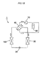
- a vehicle air-conditioning refrigeration cycle 1 illustrated in Fig. 1 includes: a compressor 10 configured to compress coolant; an expansion apparatus 20 configured to expand the compressed the coolant; a first heat exchanger 100 configured to exchange heat between air outside a cabin of a vehicle and the coolant; a second heat exchanger 30 configured to exchange heat between air inside a cabin of the vehicle and the coolant; and a coolant flow channel switching device 40 configured to switch a flow of the coolant between a cooling operation and a warming operation.
- the illustrated coolant flow channel switching device 40 is a so-called four-way valve. Gaseous coolant separated by an accumulator 50 is sent to the compressor 10.
- a flow channel in which the coolant circulates is formed by connecting the compressor 10, the expansion apparatus 20, the first heat exchanger 100, the second heat exchanger 30, the coolant flow channel switching device 40, and the accumulator 50 with pipes.
- the coolant compressed by the compressor 10 is cooled by the first heat exchanger 100, and is expanded by the expansion apparatus 20, whereby air in the cabin of the vehicle is cooled by the second heat exchanger 30 (see Fig. 1A ).
- the coolant compressed by the compressor 10 heats air in the cabin of the vehicle by the second heat exchanger 30, is expanded by the expansion apparatus 20, and is heated by the first heat exchanger 100 (see Fig. 1B ).
- the coolant circulating in the first heat exchanger 100 radiates heat to air outside the cabin during the cooling operation, and absorbs heat from air outside the cabin during the warming operation.
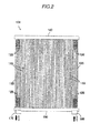
- the first heat exchanger 100 includes a plurality of tubes 110 arranged in parallel to each other, a plurality of corrugate fins 120 provided between the plurality of tubes 110, a first header 140 to which one of ends of each of the plurality of tubes 110 is connected, a second header 150 to which the other end of each of the plurality of tubes 110 is connected, a first piping joint 160 provided on the first header 140 or the second header 150, and a second piping joint 170 provided on the first header 140 or the second header 150.
- Reference numeral 130 in the drawing denotes a side plate, which is a reinforcing member.
- the first header (140) and the second header (150) are partitioned in the interiors thereof by partitioning devices 141 and 151, respectively, at predetermined intervals.
- the plurality of tubes 110 constitute a plurality of tube sets A, B, C, and D in accordance with intervals of the interiors of the first header 140 and the second header 150 partitioned by the partitioning devices 141 and 151. Three or more of tube sets A, B, C, and D are provided.
- the coolant flowed in from one of the first piping joint 160 and the second piping joint 170 passes through the plurality of tube sets A, B, C and D while exchanging heat with air outside the cabin of the vehicle and flows out from the other one of the first piping joint160 and the second piping joint 170.
- the plurality of tubes 110 are arranged so that one end is oriented upward and the other end is oriented downward with respect to a vertical direction of the vehicle.
- the first piping joint 160 or the second piping joint 170 configured to flow out the coolant during the cooling operation is provided on the second header 150.
- the illustrated first heat exchanger 100 is configured to allow the coolant to flow in from the first piping joint 160 and to flow out from the second piping joint 170 during the cooling operation.
- the second piping joint 170 is provided on the second header 150.
- the coolant flows from the four-way valve reversely, and hence the coolant flows in from the second piping joint 170 and flows out from the first piping joint 160.
- the first piping joint 160 or the second piping joint 170 configured to allow the coolant to flow in during the cooling operation is provided on the first header 140 if the number of the tube sets A, B, C, and D is an odd number, and is provided on the second header 150 if the number of the tube sets A, B, C, and D is an even number.
- the illustrated first heat exchanger 100 includes four of the tube sets A, B, C, and D.
- the number of the tube sets is an even number, and both of the first piping joint 160 and the second piping joint 170 are provided on the second header 150. If the first piping joint 160 is provided on the first header 140, a height of the pipe to be connected to the first piping joint 160 and a height of the pipe to be connected to the second piping joint 170 are significantly different. However, according to the example, these heights may be set to be the same or substantially the same. Therefore, a piping structure is simplified, and a pipe connection work is also facilitated.
- the tube sets A and C in which the coolant moves upward during the cooling operation and the tube sets B and D in which the coolant moves downward are arranged alternately.
- upward movement and downward movement of the coolant in the tube sets A, B, C, and D are inverted.
- the number of tubes in the tube sets A, B, C, and D is set to the same so that the total cross-sectional areas of the flow channel become equivalent.
- the illustrated tube sets A, B, C, and D each include the 10 tubes 110.
- the desirable number of the tubes 110 falls within a range from 6 to 15.
- the number of the tubes 110 in the respective tube sets A, B, C, and D is basically the same. However, from the reason of effective usage of the space for mounting the first heat exchanger 100 on the vehicle or the like, one or two differences in the number of the pipes are allowable.
- a length LT of the tubes 110 is set to be 0.9 m or shorter, and is set to fall within a range from 0.15 to 0.90 m.
- the width W occupied by the plurality of tubes 110 and the plurality of corrugate fins 120 is set to fall within a range from 0.40 to 0.80 m.
- the pitch of the tubes 110 is set to fall within a range from 6 to 10 mm.
- the total cross-sectional area of the flow channel of the coolant in the respective tube sets A, B, C, and D is set to fall within a range from 150 to 500 mm 2 .
- An flowing amount of the coolant of the first heat exchanger 100 during the cooling operation falls within a range from 50 to 250 kg/h.
- the flowing amount of the coolant of the first heat exchanger 100 during the warming operation falls within a range from 50 to 150 kg/h.
- the first heat exchanger 100 allows easy running of dew condensation water along the tubes 110 and, in addition, ensures sufficient radiating performance and the heat absorbing performance. Consequently, cooling and warming performance of the vehicle air-conditioning refrigeration cycle is improved.
- the idea will be descried.
- the coolant flowing into the interior of the heat exchanger 100 during the cooling operation is gaseous coolant.
- the coolant is flowed through the plurality of tube sets A, B, C, and D while radiating heat, and the percentage of the liquid-state coolant condensed by heat radiation gradually increases.
- the first piping joint 160 or the second piping joint 170 configured to flow out the coolant during the cooling operation is provided on the second header 150. In this configuration, during the cooling operation the coolant moves downward in the tube set D where the coolant passes at the end, and hence the liquid-state coolant is prevented from staying in the tube set D.
- the tube sets A and C in which the coolant moves upward during the cooling operation are subjected to easy stay of the condensed coolant. From this point, if the number of the tube sets A, B, C, and D is increased, the total cross-sectional area of the flow channels of the coolant in the respective tube sets A, B, C, and D is decreased, so that a flow rate of the coolant is increased. Consequently, the flow of the coolant is smoothened, and the circumstance in which the condensed coolant tends to stay is resolved.
- the inventors of this application conducted test production and verification experiments on the first heat exchanger 100 repeatedly for obtaining superior cooling and warming performances, and achieved the vehicle air-conditioning refrigeration cycle 1 of this example.
- the fact that the configuration of this example is extremely effective is confirmed by comparative experiments with test products produced under different conditions.
- the vehicle air-conditioning refrigeration cycle of this example achieves improvement of the cooling and warming performances by specifying desirable conditions of the first heat exchanger configured to exchange heat between the air outside the cabin of the vehicle and the coolant.
- the configuration of the respective portions of the example may be modified in design as needed within the technical scope described in Claims, and is not limited to those illustrated and described.
- the four-way valves are employed as the coolant flow channel switching device.
- the apparatus disclosed in Patent literature 1 a configuration in which two each of the expansion apparatus and the second heat exchangers are provided, and the expansion apparatus and the second heat exchangers are switched during cooling operation and during warming operation by switching the flow channels by an opening-and-closing valve is also applicable. In this case, the coolant does not flow reversely.
- the invention may be used suitably as a vehicle air-conditioning refrigeration cycle to be mounted on electric vehicles or hybrid cars.
Landscapes
- Engineering & Computer Science (AREA)
- Physics & Mathematics (AREA)
- Mechanical Engineering (AREA)
- Thermal Sciences (AREA)
- General Engineering & Computer Science (AREA)
- Air-Conditioning For Vehicles (AREA)
- Heat-Exchange Devices With Radiators And Conduit Assemblies (AREA)
- Details Of Heat-Exchange And Heat-Transfer (AREA)
Abstract
Description
- The present invention relates to a vehicle air-conditioning refrigeration cycle configured to perform cooling and warming in a cabin of a vehicle, and improved in cooling and warming performance by specifying suitable conditions of a heat exchanger being used as a radiator of a refrigeration cycle at the time of cooling and as a heat absorber of a heat pump at the time of warming.
- In general, warming in a cabin of a vehicle is performed by using heat of an internal combustion engine. In contrast, those having a vehicle drive system having a relatively lower calorific power such as electric vehicles and hybrid cars employ a refrigeration cycle configured to perform cooling of the interior of the cabin which also operates as a heat pump configured to perform warming, so that a configuration in which both cooling and warming are performed in the refrigeration cycle as described above is employed.
Patent literature 1 discloses an apparatus of a type described above. - In the case where cooling and warming are performed in the refrigeration cycle, a heat exchanger configured to exchange heat between air outside the cabin of the vehicle and coolant is used as a radiator in the refrigeration cycle at the time of cooling and used as a heat absorber of the heat pump at the time of warming.
- The heat exchanger having the configuration as described above has a problem of lowering of heat exchanging efficiency due to lowering of an amount of air passage caused by frozen dew condensation water when being used as a heat absorber. In particular, since a surface of the heat exchanger which is in contact with air has a dense configuration in view of a performance of heat exchange and mounting space, countermeasures for freezing are important for those mounted on vehicles.
- For example, Patent literature 2, Patent literature 3, and Patent literature 4 disclose heat exchangers having a plurality of tubes arranged in parallel to each other, in which the plurality of tubes are arranged so that one end is oriented upward and the other end is oriented downward with respect to a vertical direction of the vehicle. This configuration has an advantage that dew condensation water can easily flow along the tubes downward in comparison with the heat exchangers having a plurality of tubes arranged horizontally. When freezing is in progress, the frozen state may be canceled by using the heat exchanger temporarily as a radiator of the refrigeration cycle. This is also referred to as a restoration operation. If the configuration allows melted water to run along the tubes downward easily, time required for the restoration operation is advantageously reduced.
-
- PTL 1 : Japanese Patent No.
3486851 - PTL 2 :
JP-A-9-280754 - PTL 3 :
JP-A-2004-177082 - PTL 4 :
JP-A-2004-271143 - A heat exchanger configured to exchange heat between air outside a cabin of a vehicle and coolant needs to have a configuration which is capable of achieving a radiating performance for the case of being used as a radiator and a heat absorbing performance for the case of being used as a heat absorber.
- The heat exchanger of this type has a configuration in which both ends of a plurality of tubes are connected respectively to a pair of headers, and a first piping joint and a second piping joint configured to flow out and in of a coolant are provided at predetermined positions of the pair of headers. Normally, in order to improve heat exchange efficiency of coolant, a configuration in which heat exchange is effected uniformly over the entire circulating coolant is recommended. Specifically, the interiors of the respective headers are partitioned by partitioning devices, and the plurality of tubes constitute a plurality of tube sets in accordance with intervals of the interiors of the respective headers partitioned by the partitioning devices. In other words, the heat exchanger is set to allow the coolant to circulate in the plurality of tube sets and move between the headers by a plurality of times in order to uniformize the heat exchange of the coolant.
- In the case of arranging the plurality of tubes so that one end is oriented upward and the other end is oriented downward with respect to a vertical direction of the vehicle as described above, tube sets in which the coolant moves upward and the tube sets in which the coolant moves downward are arranged alternately. Therefore, the circulating state of the coolant differs significantly from one tube set to another, so that a further structural contraption is needed while considering such circumstance in order to improve the heat exchange efficiency.
- Inventors of this application have repeated test production and experiment of the vehicle air-conditioning refrigeration cycle for cooling and warming while considering a radiating performance, a heat absorbing performance, and countermeasures for freezing required for the heat exchanger, and achieved specification of a significantly superior configuration as a result of earnest inspection and reached the invention.
- In view of such circumstances, it is an object of the invention to improve cooling and worming performances of the vehicle air-conditioning refrigeration cycle.
- A first aspect of the invention is a vehicle air-conditioning refrigeration cycle (1) including:
- a compressor (10) configured to compress coolant; an expansion apparatus (20) configured to expand the compressed coolant;
- a first heat exchanger (100) configured to exchange heat between air outside a cabin of the vehicle and the coolant;
- a second heat exchanger (30) configured to exchange heat between air in the cabin of the vehicle and the coolant; and
- a coolant flow channel switching device (40) configured to switch a flow of the coolant between a cooling operation and a warming operation,
- the first heat exchanger (100) including: a plurality of tubes (110,110) arranged in parallel to each other; a plurality of corrugate fins (120,120) provided between the plurality of tubes (110); a first header (140) to which one of the ends of each of the plurality of tubes (110,110) is connected; a second header (150) to which the other end of each of the plurality of tubes (110,110) is connected; a first piping joint (160) provided on the first header (140) or the second header (150) ; a second piping joint (170) provided on the first header (140) or the second header (150);
- the first header (140) and the second header (150) are partitioned in the interiors thereof by partitioning devices (141, 151), respectively,
- the plurality of tubes (110, 110) constitute a plurality of tube sets (A, B, C, and D) in accordance with intervals of the interiors of the first header (140) and the second header (150) partitioned by the partitioning devices (141,151), and the coolant flowed in from one of the first piping joint (160) and the second piping joint (170) passes through the plurality of tube sets (A, B, C, and D) while exchanging heat with air outside the cabin of the vehicle and flows out from the other one of the first piping joint (160) and the second piping joint (170), wherein
- the plurality of tubes (110,110) are arranged so that one end is oriented upward and the other end is oriented downward with respect to the vertical direction of the vehicle,
- the first piping joint (160) or the second piping joint (170) configured to flow out the coolant during the cooling operation is provided on the second header (150), and
- three or more of the tube sets (A, B, C, and D) are provided.
- In a second aspect of the invention, the vehicle air-conditioning refrigeration cycle (1) according to the first aspect has a configuration in which the number of the tube sets (A, B, C, and D) is an even number, and both of the first piping joint (160) and the second piping joint (170) are provided on the second header (150).
- In a third aspect of the invention, the vehicle air-conditioning refrigeration cycle (1) according to the first or second aspect has a configuration in which the number of the tube sets (A, B, C, and D) falls within a range from 4 to 6.
- In a fourth aspect of the invention, the vehicle air-conditioning refrigeration cycle (1) according to any of the first to third aspects has a configuration in which a length of the tubes (110,110) is 0.9 m or shorter.
- In a fifth aspect of the invention, the vehicle air-conditioning refrigeration cycle (1) according to the fourth aspect has a configuration in which a total cross-sectional area of flow channels of the coolant in the tube sets (A, B, C, and D) falls within a range from 150 to 500 mm2.
- A sixth aspect of the invention is a heat exchanger (100) configured to be used in a vehicle air-conditioning refrigeration cycle for cooling and warming a cabin of a vehicle and exchange heat between air outside the cabin of the vehicle and coolant, including:
- the plurality of tubes (110,110) arranged in parallel to each other; the plurality of corrugate fins (120,120) provided between the plurality of tubes (110,110); the first header (140) to which one of the ends of each of the plurality of tubes (110,110) is connected; the second header (150) to which the other end of each of the plurality of tubes (110, 110) is connected; the first piping joint (160) provided on the first header (140) or the second header (150) ; and the second piping joint (170) provided on the first header (140) or the second header (150);
- the first header (140) and the second header (150) are partitioned in the interiors thereof by the partitioning devices (141,151), respectively,
- the plurality of tubes (110,110) constitute the plurality of tube sets (A, B, C, and D) in accordance with intervals of the interiors of the first header (140) and the second header (150) partitioned by the partitioning devices (141,151),
- the coolant flowed in from one of the first piping joint (160) and the second piping joint (170) passes through the plurality of tube sets (A, B, C, and D) while exchanging heat with air outside the cabin of the vehicle and flows out from the other one of the first piping joint (160) and the second piping joint (170),
- the plurality of tubes (110,110) are arranged so that one end is oriented upward and the other end is oriented downward with respect to the vertical direction of the vehicle, the first piping joint (160) or the second piping joint (170) configured to flow out the coolant during the cooling operation is provided on the second header (150), and three or more of the tube sets (A, B, C, and D) are provided.
- In a seventh aspect of the invention, the heat exchanger (100) according to the sixth aspect has a configuration in which the number of the tube sets (A, B, C, and D) is an even number, and both of the first piping joint (160) and the second piping joint (170) are provided on the second header (150).
- In an eighth aspect of the invention, the heat exchanger (100) according to the sixth or seventh aspect has a configuration in which the number of the tube sets falls within a range from 4 to 6.
- In a ninth aspect of the invention, the heat exchanger (100) according to any of the sixth to eighth aspects has a configuration in which a length of the tubes (110,110) is 0.9 m or shorter.
- In a tenth aspect of the invention, the heat exchanger (100) according to the ninth aspect has a configuration in which a total cross-sectional area of flow channels of the coolant in the tube sets (A, B, C, and D) falls within a range from 150 to 500 mm2.
- According to the invention, an improvement of the cooling and warming performance of the vehicle air-conditioning refrigeration cycle is achieved.
-
-
Fig. 1A is an explanatory drawing of an example of a vehicle air-conditioning refrigeration cycle of the invention illustrating a flow of coolant during a cooling operation with black arrows; -
Fig. 1B is an explanatory drawing of an example of the vehicle air-conditioning refrigeration cycle of the invention illustrating a flow of the coolant during a warming operation with hollow arrows; -
Fig. 2 is a front view of a first heat exchanger according to the example of the invention, in which the black arrows indicate a flow of the coolant during the cooling operation and the hollow arrows indicate a flow of the coolant during the warming operation; and -
Fig. 3 is an explanatory drawing illustrating a structure of the first heat exchanger according to the example of the invention, in which the black arrows indicate a flow of the coolant during the cooling operation and the hollow arrows indicate a flow of the coolant during the warming operation. - An example of the invention will be described with reference to the drawings. A vehicle air-
conditioning refrigeration cycle 1 illustrated inFig. 1 includes: acompressor 10 configured to compress coolant; anexpansion apparatus 20 configured to expand the compressed the coolant; afirst heat exchanger 100 configured to exchange heat between air outside a cabin of a vehicle and the coolant; asecond heat exchanger 30 configured to exchange heat between air inside a cabin of the vehicle and the coolant; and a coolant flowchannel switching device 40 configured to switch a flow of the coolant between a cooling operation and a warming operation. The illustrated coolant flowchannel switching device 40 is a so-called four-way valve. Gaseous coolant separated by anaccumulator 50 is sent to thecompressor 10. A flow channel in which the coolant circulates is formed by connecting thecompressor 10, theexpansion apparatus 20, thefirst heat exchanger 100, thesecond heat exchanger 30, the coolant flowchannel switching device 40, and theaccumulator 50 with pipes. During the cooling operation, the coolant compressed by thecompressor 10 is cooled by thefirst heat exchanger 100, and is expanded by theexpansion apparatus 20, whereby air in the cabin of the vehicle is cooled by the second heat exchanger 30 (seeFig. 1A ). During the warming operation, the coolant compressed by thecompressor 10 heats air in the cabin of the vehicle by thesecond heat exchanger 30, is expanded by theexpansion apparatus 20, and is heated by the first heat exchanger 100 (seeFig. 1B ). In other words, the coolant circulating in thefirst heat exchanger 100 radiates heat to air outside the cabin during the cooling operation, and absorbs heat from air outside the cabin during the warming operation. - As illustrated in
Fig. 2 andFig. 3 , thefirst heat exchanger 100 includes a plurality oftubes 110 arranged in parallel to each other, a plurality ofcorrugate fins 120 provided between the plurality oftubes 110, afirst header 140 to which one of ends of each of the plurality oftubes 110 is connected, asecond header 150 to which the other end of each of the plurality oftubes 110 is connected, a first piping joint 160 provided on thefirst header 140 or thesecond header 150, and a second piping joint 170 provided on thefirst header 140 or thesecond header 150.Reference numeral 130 in the drawing denotes a side plate, which is a reinforcing member. - The first header (140) and the second header (150) are partitioned in the interiors thereof by partitioning
devices tubes 110 constitute a plurality of tube sets A, B, C, and D in accordance with intervals of the interiors of thefirst header 140 and thesecond header 150 partitioned by thepartitioning devices first piping joint 160 and the second piping joint 170 passes through the plurality of tube sets A, B, C and D while exchanging heat with air outside the cabin of the vehicle and flows out from the other one of the first piping joint160 and thesecond piping joint 170. - The plurality of
tubes 110 are arranged so that one end is oriented upward and the other end is oriented downward with respect to a vertical direction of the vehicle. - The first piping joint 160 or the second piping joint 170 configured to flow out the coolant during the cooling operation is provided on the
second header 150. - The illustrated
first heat exchanger 100 is configured to allow the coolant to flow in from thefirst piping joint 160 and to flow out from the second piping joint 170 during the cooling operation. In other words, thesecond piping joint 170 is provided on thesecond header 150. During the warming operation, the coolant flows from the four-way valve reversely, and hence the coolant flows in from thesecond piping joint 170 and flows out from thefirst piping joint 160. - The first piping joint 160 or the second piping joint 170 configured to allow the coolant to flow in during the cooling operation is provided on the
first header 140 if the number of the tube sets A, B, C, and D is an odd number, and is provided on thesecond header 150 if the number of the tube sets A, B, C, and D is an even number. - The illustrated
first heat exchanger 100 includes four of the tube sets A, B, C, and D. The number of the tube sets is an even number, and both of thefirst piping joint 160 and the second piping joint 170 are provided on thesecond header 150. If thefirst piping joint 160 is provided on thefirst header 140, a height of the pipe to be connected to thefirst piping joint 160 and a height of the pipe to be connected to the second piping joint 170 are significantly different. However, according to the example, these heights may be set to be the same or substantially the same. Therefore, a piping structure is simplified, and a pipe connection work is also facilitated. - As regards the arrangement of the tube sets A, B, C, and D, the tube sets A and C in which the coolant moves upward during the cooling operation and the tube sets B and D in which the coolant moves downward are arranged alternately. During the warming operation, upward movement and downward movement of the coolant in the tube sets A, B, C, and D are inverted.
- The number of tubes in the tube sets A, B, C, and D is set to the same so that the total cross-sectional areas of the flow channel become equivalent. The illustrated tube sets A, B, C, and D each include the 10
tubes 110. The desirable number of thetubes 110 falls within a range from 6 to 15. The number of thetubes 110 in the respective tube sets A, B, C, and D is basically the same. However, from the reason of effective usage of the space for mounting thefirst heat exchanger 100 on the vehicle or the like, one or two differences in the number of the pipes are allowable. - In the case of this example, a length LT of the
tubes 110 is set to be 0.9 m or shorter, and is set to fall within a range from 0.15 to 0.90 m. The width W occupied by the plurality oftubes 110 and the plurality ofcorrugate fins 120 is set to fall within a range from 0.40 to 0.80 m. The pitch of thetubes 110 is set to fall within a range from 6 to 10 mm. The total cross-sectional area of the flow channel of the coolant in the respective tube sets A, B, C, and D is set to fall within a range from 150 to 500 mm2. An flowing amount of the coolant of thefirst heat exchanger 100 during the cooling operation falls within a range from 50 to 250 kg/h. The flowing amount of the coolant of thefirst heat exchanger 100 during the warming operation falls within a range from 50 to 150 kg/h. - In this configuration, the
first heat exchanger 100 allows easy running of dew condensation water along thetubes 110 and, in addition, ensures sufficient radiating performance and the heat absorbing performance. Consequently, cooling and warming performance of the vehicle air-conditioning refrigeration cycle is improved. Hereinafter, the idea will be descried. - According to the experiment conducted by the inventors of this application, it was found that freezing of the surfaces of the tube sets B and D in which the coolant moves upward during the warming operation occurs at a slower rate than that of the tube sets A and C in which the coolant moves downward at that time. The coolant flowing into the interior of the
heat exchanger 100 is mixture of gaseous coolant and liquid-state coolant. It is considered that liquid-state coolant can hardly stay in the tube sets A and C in which the coolant moves downward. A space for allowing the coolant to evaporate is secured, and hence heat absorption is sufficiently performed. In contrast, it is considered that liquid-state coolant can easily stay in the tube sets B and D in which the coolant moves upward. If the liquid-state coolant stays, the space to allow the coolant to evaporate is not large even though the heat absorption is effected, so that quick heat absorption is not achieved, and freezing occurs at a relatively slower rate. Therefore, with the configuration having the tube sets B and D in which the coolant moves upward during the warming operation and the tube sets A and C in which the coolant moves downward, freezing of entire surface may be delayed. This configuration resists occurrence of a situation in which the ventilation flues of air, that is, the entire gaps between the plurality oftubes 110 and the plurality ofcorrugate fins 120 are frozen. Depending on the experiment, the heat absorbing performance is secured satisfactorily. - During the cooling operation, it is desirable to let the condensed liquid-state coolant to be flowed out quickly from the
first heat exchanger 100. The coolant flowing into the interior of theheat exchanger 100 during the cooling operation is gaseous coolant. The coolant is flowed through the plurality of tube sets A, B, C, and D while radiating heat, and the percentage of the liquid-state coolant condensed by heat radiation gradually increases. The first piping joint 160 or the second piping joint 170 configured to flow out the coolant during the cooling operation is provided on thesecond header 150. In this configuration, during the cooling operation the coolant moves downward in the tube set D where the coolant passes at the end, and hence the liquid-state coolant is prevented from staying in the tube set D. If the liquid-state coolant is flowed out quickly, the space for radiating heat from the gaseous coolant is secured. Consequently, the radiating performance is reliably improved. According to the experiment, with the provision of three or more of the tube sets A, B, C, and D, the satisfactory radiating performance is secured. - The tube sets A and C in which the coolant moves upward during the cooling operation are subjected to easy stay of the condensed coolant. From this point, if the number of the tube sets A, B, C, and D is increased, the total cross-sectional area of the flow channels of the coolant in the respective tube sets A, B, C, and D is decreased, so that a flow rate of the coolant is increased. Consequently, the flow of the coolant is smoothened, and the circumstance in which the condensed coolant tends to stay is resolved. As a matter of course, if the number of the tube sets A, B, C, and D is increased too much, the total cross-sectional area of the flow channels of the coolant in the respective tube sets A, B, C, and D is also decreased, so that the coolant cannot flow easily. In such a case, a motive power of the
compressor 10 is increased. When a test experiment was conducted in view of such circumstances while confirming performances during the cooling operation and the warming operation, respectively, the practical number of the tube sets A, B, C, and D was within a range from 3 to 8, and the optimal number fell within a range from 4 to 6. - The inventors of this application conducted test production and verification experiments on the
first heat exchanger 100 repeatedly for obtaining superior cooling and warming performances, and achieved the vehicle air-conditioning refrigeration cycle 1 of this example. The fact that the configuration of this example is extremely effective is confirmed by comparative experiments with test products produced under different conditions. - As described thus far, the vehicle air-conditioning refrigeration cycle of this example achieves improvement of the cooling and warming performances by specifying desirable conditions of the first heat exchanger configured to exchange heat between the air outside the cabin of the vehicle and the coolant. The configuration of the respective portions of the example may be modified in design as needed within the technical scope described in Claims, and is not limited to those illustrated and described.
- For example, in this example, the four-way valves are employed as the coolant flow channel switching device. Alternatively, however, as the apparatus disclosed in
Patent literature 1, a configuration in which two each of the expansion apparatus and the second heat exchangers are provided, and the expansion apparatus and the second heat exchangers are switched during cooling operation and during warming operation by switching the flow channels by an opening-and-closing valve is also applicable. In this case, the coolant does not flow reversely. - The invention may be used suitably as a vehicle air-conditioning refrigeration cycle to be mounted on electric vehicles or hybrid cars.
-
- 1
- vehicle air-conditioning refrigeration cycle
- 10
- compressor
- 20
- expansion apparatus
- 30
- second heat exchanger
- 40
- coolant flow channel switching device
- 50
- accumulator
- 100
- first heat exchanger
- 110
- tube
- 120
- corrugate fin
- 130
- side plate
- 140
- first header
- 141
- partitioning device
- 150
- second header
- 151
- partitioning device
- 160
- first piping joint
- 170
- second piping joint
Claims (10)
- A vehicle air-conditioning refrigeration cycle (1) comprising:a compressor (10) configured to compress coolant;an expansion apparatus (20) configured to expand the compressed coolant;a first heat exchanger (100) configured to exchange heat between air outside a cabin of a vehicle and the coolant;a second heat exchanger (30) configured to exchange heat between air in the cabin of the vehicle and the coolant; anda coolant flow channel switching device (40) configured to switch a flow of the coolant between a cooling operation and a warming operation,the first heat exchanger (100) includes:a plurality of tubes (110,110) arranged in parallel to each other;a plurality of corrugate fins (120, 120) provided between the plurality of tubes (110,110);a first header (140) to which one of the ends of each of the plurality of tubes (110,110) is connected;a second header (150) to which the other one of the ends of each of the plurality of tubes (110,110) is connected;a first piping joint (160) provided on the first header (140) or the second header (150);a second piping joint (170) provided on the first header (140) or the second header (150);the first header (140) and the second header (150) are partitioned in the interiors thereof by partitioning devices (141, 151), respectively, the plurality of tubes (110,110) constitute a plurality of tube sets (A, B, C, and D) in accordance with intervals of the interiors of the first header (140) and the second header (150) partitioned by the partitioning devices (141,151), and the coolant flowed from one of the first piping joint (160) and the second piping joint (170) passes through the plurality of tube sets (A, B, C, and D) while exchanging heat with air outside the cabin of the vehicle and flows out from the other one of the first piping joint (160) and the second piping joint (170), whereinthe plurality of tubes (110, 110) are arranged so that one end is oriented upward and the other end is oriented downward with respect to a vertical direction of the vehicle,the first piping joint (160) or the second piping joint (170) configured to flow out the coolant during the cooling operation is provided on the second header (150), andthree or more of the tube sets (A, B, C, and D) are provided.
- The vehicle air-conditioning refrigeration cycle (1) according to Claim 1, wherein
the number of the tube sets (A, B, C, and D) is an even number, and both of the first piping joint (160) and the second piping joint (170) are provided on the second header (150). - The vehicle air-conditioning refrigeration cycle (1) according to Claim 1 or 2, wherein
the number of the tube sets (A, B, C, and D) falls within a range from 4 to 6. - The vehicle air-conditioning refrigeration cycle (1) according to any one of Claims 1 to 3, wherein
a length of the tubes (110,110) is 0.9 m or shorter. - The vehicle air-conditioning refrigeration cycle (1) according to Claim 4, wherein
a total cross-sectional area of flow channels of the coolant in the tube sets (A, B, C, and D) falls within a range from 150 to 500 mm2. - A heat exchanger (100) configured to be used in a vehicle air-conditioning refrigeration cycle (1) for cooling and warming a cabin of a vehicle and exchange heat between air outside the cabin of the vehicle and coolant, comprising:a plurality of tubes (110, 110) arranged in parallel to each other;a plurality of corrugate fins (120, 120) provided between the plurality of tubes(110,110);a first header (140) to which one of the ends of each of the plurality of tubes (110,110) is connected;a second header (150) to which the other one of the ends of each of the plurality of tubes is connected;a first piping joint (160) provided on the first header (140) or the second header (150); anda second piping joint (170) provided on the first header (140) or the second header (150),the first header (140) and the second header (150) are partitioned in the interiors thereof by partitioning devices (141,151), respectively, the plurality of tubes (110,110) constitute a plurality of tube sets (A, B, C, and D) in accordance with intervals of the interiors of the first header (140) and the second header (150) partitioned by the partitioning devices (141, 151), the coolant flowed in from one of the first piping joint (160) and the second piping joint (170) passes through the plurality of tube sets while exchanging heat with air outside the cabin of the vehicle and flows out from the other one of the first piping joint (160) and the second piping joint (170),the plurality of tubes (110, 110) are arranged so that one end is oriented upward and the other end is oriented downward with respect to the vertical direction of the vehicle,the first piping joint (160) or the second piping joint (170) configured to flow out the coolant during the cooling operation is provided on the second header (150), andthree or more of the tube sets (A, B, C, and D) are provided.
- The heat exchanger (100) according to Claim 6, wherein
the number of the tube sets (A, B, C, and D) is an even number, and both of the first piping joint (160) and the second piping joint (170) are provided on the second header (150). - The heat exchanger (100) according to Claim 6 or 7, wherein
the number of the tube sets (A, B, C, and D) falls within a range from 4 to 6. - The heat exchanger (100) according to any one of Claims 6 to 8, wherein
a length of the tubes (110,110) is 0.9 m or shorter. - The heat exchanger (100) according to Claim 9, wherein
a total cross-sectional area of flow channels of the coolant in the tube sets (A, B, C, and D) falls within a range from 150 to 500 mm2.
Applications Claiming Priority (2)
| Application Number | Priority Date | Filing Date | Title |
|---|---|---|---|
| JP2012204108 | 2012-09-18 | ||
| PCT/JP2013/074611 WO2014045983A1 (en) | 2012-09-18 | 2013-09-12 | Refrigeration cycle for air conditioning vehicle, and heat exchanger |
Publications (3)
| Publication Number | Publication Date |
|---|---|
| EP2918959A1 true EP2918959A1 (en) | 2015-09-16 |
| EP2918959A4 EP2918959A4 (en) | 2016-08-10 |
| EP2918959B1 EP2918959B1 (en) | 2019-11-13 |
Family
ID=50341297
Family Applications (1)
| Application Number | Title | Priority Date | Filing Date |
|---|---|---|---|
| EP13838134.8A Active EP2918959B1 (en) | 2012-09-18 | 2013-09-12 | Refrigeration cycle for air conditioning vehicle, and heat exchanger |
Country Status (3)
| Country | Link |
|---|---|
| EP (1) | EP2918959B1 (en) |
| JP (1) | JP6275046B2 (en) |
| WO (1) | WO2014045983A1 (en) |
Families Citing this family (1)
| Publication number | Priority date | Publication date | Assignee | Title |
|---|---|---|---|---|
| US12152814B2 (en) * | 2020-05-22 | 2024-11-26 | Mitsubishi Electric Corporation | Heat exchanger and air-conditioning apparatus including the heat exchanger |
Family Cites Families (8)
| Publication number | Priority date | Publication date | Assignee | Title |
|---|---|---|---|---|
| JP3486851B2 (en) | 1993-05-28 | 2004-01-13 | 株式会社ゼクセルヴァレオクライメートコントロール | Air conditioner |
| JP3214318B2 (en) * | 1995-10-31 | 2001-10-02 | 株式会社デンソー | Outdoor heat exchanger for heat pump refrigeration cycle |
| JP3942210B2 (en) | 1996-04-16 | 2007-07-11 | 昭和電工株式会社 | Heat exchanger, room air conditioner and car air conditioner using this heat exchanger |
| US6062303A (en) * | 1997-09-26 | 2000-05-16 | Halla Climate Control Corp. | Multiflow type condenser for an air conditioner |
| JP2004177082A (en) | 2002-11-29 | 2004-06-24 | Matsushita Electric Ind Co Ltd | Heat exchanger |
| JP2004271143A (en) | 2003-03-12 | 2004-09-30 | Japan Climate Systems Corp | Heat exchanger |
| JP2007278558A (en) * | 2006-04-04 | 2007-10-25 | Denso Corp | Refrigerant radiator |
| JP5421933B2 (en) * | 2011-01-12 | 2014-02-19 | サンデン株式会社 | Heat exchanger |
-
2013
- 2013-09-12 WO PCT/JP2013/074611 patent/WO2014045983A1/en not_active Ceased
- 2013-09-12 JP JP2014536789A patent/JP6275046B2/en active Active
- 2013-09-12 EP EP13838134.8A patent/EP2918959B1/en active Active
Also Published As
| Publication number | Publication date |
|---|---|
| WO2014045983A1 (en) | 2014-03-27 |
| EP2918959B1 (en) | 2019-11-13 |
| EP2918959A4 (en) | 2016-08-10 |
| JPWO2014045983A1 (en) | 2016-08-18 |
| JP6275046B2 (en) | 2018-02-07 |
Similar Documents
| Publication | Publication Date | Title |
|---|---|---|
| DE102009029629B4 (en) | Heat exchangers for temperature control of vehicle batteries | |
| CN110014820B (en) | Cooling module | |
| JP2008080995A (en) | Cooling system | |
| JP5274175B2 (en) | Cold storage heat exchanger | |
| JP6214670B2 (en) | Heat exchanger and refrigeration cycle apparatus using the heat exchanger | |
| US20160033211A1 (en) | Oil cooler | |
| JP6002583B2 (en) | Evaporator | |
| US20150285544A1 (en) | Refrigerant evaporator | |
| US20150241080A1 (en) | Air-conditioning apparatus for vehicle | |
| WO2015045105A1 (en) | Heat exchanger and air conditioner using same | |
| EP2918959B1 (en) | Refrigeration cycle for air conditioning vehicle, and heat exchanger | |
| JP2019105380A (en) | Heat exchanger | |
| JP2010234974A (en) | Evaporator with cold storage function | |
| EP3137836B1 (en) | Improved heat exchanger | |
| JP6097520B2 (en) | Evaporator with cool storage function | |
| JP2013257095A (en) | Finless heat exchanger | |
| WO2017168669A1 (en) | Heat exchanger and refrigeration cycle apparatus | |
| US20180029438A1 (en) | Device for heat transfer and method for operating the device | |
| JP2017116195A (en) | Evaporator with cold storage function | |
| US20160296993A1 (en) | Method for forming end plate for heat exchanger and heat exchanger equipped with end plate formed with this method | |
| KR102942818B1 (en) | Heat exchanger | |
| JP2014095523A (en) | Evaporator | |
| JP4355604B2 (en) | Heat exchange system | |
| JP2015081689A (en) | Outdoor heat exchanger for heat pump-type refrigeration cycle | |
| KR101650088B1 (en) | A heat exchanger |
Legal Events
| Date | Code | Title | Description |
|---|---|---|---|
| PUAI | Public reference made under article 153(3) epc to a published international application that has entered the european phase |
Free format text: ORIGINAL CODE: 0009012 |
|
| 17P | Request for examination filed |
Effective date: 20150416 |
|
| AK | Designated contracting states |
Kind code of ref document: A1 Designated state(s): AL AT BE BG CH CY CZ DE DK EE ES FI FR GB GR HR HU IE IS IT LI LT LU LV MC MK MT NL NO PL PT RO RS SE SI SK SM TR |
|
| AX | Request for extension of the european patent |
Extension state: BA ME |
|
| DAX | Request for extension of the european patent (deleted) | ||
| RA4 | Supplementary search report drawn up and despatched (corrected) |
Effective date: 20160711 |
|
| RIC1 | Information provided on ipc code assigned before grant |
Ipc: F25B 39/04 20060101ALI20160705BHEP Ipc: B60H 1/32 20060101ALI20160705BHEP Ipc: F28F 9/02 20060101AFI20160705BHEP Ipc: F25B 13/00 20060101ALI20160705BHEP |
|
| STAA | Information on the status of an ep patent application or granted ep patent |
Free format text: STATUS: EXAMINATION IS IN PROGRESS |
|
| 17Q | First examination report despatched |
Effective date: 20180726 |
|
| GRAP | Despatch of communication of intention to grant a patent |
Free format text: ORIGINAL CODE: EPIDOSNIGR1 |
|
| STAA | Information on the status of an ep patent application or granted ep patent |
Free format text: STATUS: GRANT OF PATENT IS INTENDED |
|
| RIN1 | Information on inventor provided before grant (corrected) |
Inventor name: IIJIMA KENJI |
|
| INTG | Intention to grant announced |
Effective date: 20190618 |
|
| GRAS | Grant fee paid |
Free format text: ORIGINAL CODE: EPIDOSNIGR3 |
|
| GRAA | (expected) grant |
Free format text: ORIGINAL CODE: 0009210 |
|
| STAA | Information on the status of an ep patent application or granted ep patent |
Free format text: STATUS: THE PATENT HAS BEEN GRANTED |
|
| AK | Designated contracting states |
Kind code of ref document: B1 Designated state(s): AL AT BE BG CH CY CZ DE DK EE ES FI FR GB GR HR HU IE IS IT LI LT LU LV MC MK MT NL NO PL PT RO RS SE SI SK SM TR |
|
| REG | Reference to a national code |
Ref country code: CH Ref legal event code: EP Ref country code: AT Ref legal event code: REF Ref document number: 1202118 Country of ref document: AT Kind code of ref document: T Effective date: 20191115 |
|
| REG | Reference to a national code |
Ref country code: DE Ref legal event code: R096 Ref document number: 602013062957 Country of ref document: DE |
|
| REG | Reference to a national code |
Ref country code: IE Ref legal event code: FG4D |
|
| REG | Reference to a national code |
Ref country code: NL Ref legal event code: MP Effective date: 20191113 |
|
| REG | Reference to a national code |
Ref country code: LT Ref legal event code: MG4D |
|
| PG25 | Lapsed in a contracting state [announced via postgrant information from national office to epo] |
Ref country code: GR Free format text: LAPSE BECAUSE OF FAILURE TO SUBMIT A TRANSLATION OF THE DESCRIPTION OR TO PAY THE FEE WITHIN THE PRESCRIBED TIME-LIMIT Effective date: 20200214 Ref country code: PL Free format text: LAPSE BECAUSE OF FAILURE TO SUBMIT A TRANSLATION OF THE DESCRIPTION OR TO PAY THE FEE WITHIN THE PRESCRIBED TIME-LIMIT Effective date: 20191113 Ref country code: NO Free format text: LAPSE BECAUSE OF FAILURE TO SUBMIT A TRANSLATION OF THE DESCRIPTION OR TO PAY THE FEE WITHIN THE PRESCRIBED TIME-LIMIT Effective date: 20200213 Ref country code: SE Free format text: LAPSE BECAUSE OF FAILURE TO SUBMIT A TRANSLATION OF THE DESCRIPTION OR TO PAY THE FEE WITHIN THE PRESCRIBED TIME-LIMIT Effective date: 20191113 Ref country code: LV Free format text: LAPSE BECAUSE OF FAILURE TO SUBMIT A TRANSLATION OF THE DESCRIPTION OR TO PAY THE FEE WITHIN THE PRESCRIBED TIME-LIMIT Effective date: 20191113 Ref country code: FI Free format text: LAPSE BECAUSE OF FAILURE TO SUBMIT A TRANSLATION OF THE DESCRIPTION OR TO PAY THE FEE WITHIN THE PRESCRIBED TIME-LIMIT Effective date: 20191113 Ref country code: BG Free format text: LAPSE BECAUSE OF FAILURE TO SUBMIT A TRANSLATION OF THE DESCRIPTION OR TO PAY THE FEE WITHIN THE PRESCRIBED TIME-LIMIT Effective date: 20200213 Ref country code: PT Free format text: LAPSE BECAUSE OF FAILURE TO SUBMIT A TRANSLATION OF THE DESCRIPTION OR TO PAY THE FEE WITHIN THE PRESCRIBED TIME-LIMIT Effective date: 20200313 Ref country code: NL Free format text: LAPSE BECAUSE OF FAILURE TO SUBMIT A TRANSLATION OF THE DESCRIPTION OR TO PAY THE FEE WITHIN THE PRESCRIBED TIME-LIMIT Effective date: 20191113 Ref country code: LT Free format text: LAPSE BECAUSE OF FAILURE TO SUBMIT A TRANSLATION OF THE DESCRIPTION OR TO PAY THE FEE WITHIN THE PRESCRIBED TIME-LIMIT Effective date: 20191113 |
|
| PG25 | Lapsed in a contracting state [announced via postgrant information from national office to epo] |
Ref country code: IS Free format text: LAPSE BECAUSE OF FAILURE TO SUBMIT A TRANSLATION OF THE DESCRIPTION OR TO PAY THE FEE WITHIN THE PRESCRIBED TIME-LIMIT Effective date: 20200313 Ref country code: HR Free format text: LAPSE BECAUSE OF FAILURE TO SUBMIT A TRANSLATION OF THE DESCRIPTION OR TO PAY THE FEE WITHIN THE PRESCRIBED TIME-LIMIT Effective date: 20191113 Ref country code: RS Free format text: LAPSE BECAUSE OF FAILURE TO SUBMIT A TRANSLATION OF THE DESCRIPTION OR TO PAY THE FEE WITHIN THE PRESCRIBED TIME-LIMIT Effective date: 20191113 |
|
| PG25 | Lapsed in a contracting state [announced via postgrant information from national office to epo] |
Ref country code: AL Free format text: LAPSE BECAUSE OF FAILURE TO SUBMIT A TRANSLATION OF THE DESCRIPTION OR TO PAY THE FEE WITHIN THE PRESCRIBED TIME-LIMIT Effective date: 20191113 |
|
| PG25 | Lapsed in a contracting state [announced via postgrant information from national office to epo] |
Ref country code: ES Free format text: LAPSE BECAUSE OF FAILURE TO SUBMIT A TRANSLATION OF THE DESCRIPTION OR TO PAY THE FEE WITHIN THE PRESCRIBED TIME-LIMIT Effective date: 20191113 Ref country code: DK Free format text: LAPSE BECAUSE OF FAILURE TO SUBMIT A TRANSLATION OF THE DESCRIPTION OR TO PAY THE FEE WITHIN THE PRESCRIBED TIME-LIMIT Effective date: 20191113 Ref country code: CZ Free format text: LAPSE BECAUSE OF FAILURE TO SUBMIT A TRANSLATION OF THE DESCRIPTION OR TO PAY THE FEE WITHIN THE PRESCRIBED TIME-LIMIT Effective date: 20191113 Ref country code: EE Free format text: LAPSE BECAUSE OF FAILURE TO SUBMIT A TRANSLATION OF THE DESCRIPTION OR TO PAY THE FEE WITHIN THE PRESCRIBED TIME-LIMIT Effective date: 20191113 Ref country code: RO Free format text: LAPSE BECAUSE OF FAILURE TO SUBMIT A TRANSLATION OF THE DESCRIPTION OR TO PAY THE FEE WITHIN THE PRESCRIBED TIME-LIMIT Effective date: 20191113 |
|
| REG | Reference to a national code |
Ref country code: DE Ref legal event code: R097 Ref document number: 602013062957 Country of ref document: DE |
|
| REG | Reference to a national code |
Ref country code: AT Ref legal event code: MK05 Ref document number: 1202118 Country of ref document: AT Kind code of ref document: T Effective date: 20191113 |
|
| PG25 | Lapsed in a contracting state [announced via postgrant information from national office to epo] |
Ref country code: SM Free format text: LAPSE BECAUSE OF FAILURE TO SUBMIT A TRANSLATION OF THE DESCRIPTION OR TO PAY THE FEE WITHIN THE PRESCRIBED TIME-LIMIT Effective date: 20191113 Ref country code: SK Free format text: LAPSE BECAUSE OF FAILURE TO SUBMIT A TRANSLATION OF THE DESCRIPTION OR TO PAY THE FEE WITHIN THE PRESCRIBED TIME-LIMIT Effective date: 20191113 |
|
| PLBE | No opposition filed within time limit |
Free format text: ORIGINAL CODE: 0009261 |
|
| STAA | Information on the status of an ep patent application or granted ep patent |
Free format text: STATUS: NO OPPOSITION FILED WITHIN TIME LIMIT |
|
| 26N | No opposition filed |
Effective date: 20200814 |
|
| PG25 | Lapsed in a contracting state [announced via postgrant information from national office to epo] |
Ref country code: AT Free format text: LAPSE BECAUSE OF FAILURE TO SUBMIT A TRANSLATION OF THE DESCRIPTION OR TO PAY THE FEE WITHIN THE PRESCRIBED TIME-LIMIT Effective date: 20191113 Ref country code: SI Free format text: LAPSE BECAUSE OF FAILURE TO SUBMIT A TRANSLATION OF THE DESCRIPTION OR TO PAY THE FEE WITHIN THE PRESCRIBED TIME-LIMIT Effective date: 20191113 |
|
| PG25 | Lapsed in a contracting state [announced via postgrant information from national office to epo] |
Ref country code: IT Free format text: LAPSE BECAUSE OF FAILURE TO SUBMIT A TRANSLATION OF THE DESCRIPTION OR TO PAY THE FEE WITHIN THE PRESCRIBED TIME-LIMIT Effective date: 20191113 |
|
| PG25 | Lapsed in a contracting state [announced via postgrant information from national office to epo] |
Ref country code: MC Free format text: LAPSE BECAUSE OF FAILURE TO SUBMIT A TRANSLATION OF THE DESCRIPTION OR TO PAY THE FEE WITHIN THE PRESCRIBED TIME-LIMIT Effective date: 20191113 |
|
| REG | Reference to a national code |
Ref country code: CH Ref legal event code: PL |
|
| GBPC | Gb: european patent ceased through non-payment of renewal fee |
Effective date: 20200912 |
|
| REG | Reference to a national code |
Ref country code: BE Ref legal event code: MM Effective date: 20200930 |
|
| PG25 | Lapsed in a contracting state [announced via postgrant information from national office to epo] |
Ref country code: LU Free format text: LAPSE BECAUSE OF NON-PAYMENT OF DUE FEES Effective date: 20200912 |
|
| PG25 | Lapsed in a contracting state [announced via postgrant information from national office to epo] |
Ref country code: CH Free format text: LAPSE BECAUSE OF NON-PAYMENT OF DUE FEES Effective date: 20200930 Ref country code: BE Free format text: LAPSE BECAUSE OF NON-PAYMENT OF DUE FEES Effective date: 20200930 Ref country code: LI Free format text: LAPSE BECAUSE OF NON-PAYMENT OF DUE FEES Effective date: 20200930 Ref country code: GB Free format text: LAPSE BECAUSE OF NON-PAYMENT OF DUE FEES Effective date: 20200912 Ref country code: IE Free format text: LAPSE BECAUSE OF NON-PAYMENT OF DUE FEES Effective date: 20200912 |
|
| PG25 | Lapsed in a contracting state [announced via postgrant information from national office to epo] |
Ref country code: TR Free format text: LAPSE BECAUSE OF FAILURE TO SUBMIT A TRANSLATION OF THE DESCRIPTION OR TO PAY THE FEE WITHIN THE PRESCRIBED TIME-LIMIT Effective date: 20191113 Ref country code: MT Free format text: LAPSE BECAUSE OF FAILURE TO SUBMIT A TRANSLATION OF THE DESCRIPTION OR TO PAY THE FEE WITHIN THE PRESCRIBED TIME-LIMIT Effective date: 20191113 Ref country code: CY Free format text: LAPSE BECAUSE OF FAILURE TO SUBMIT A TRANSLATION OF THE DESCRIPTION OR TO PAY THE FEE WITHIN THE PRESCRIBED TIME-LIMIT Effective date: 20191113 |
|
| PG25 | Lapsed in a contracting state [announced via postgrant information from national office to epo] |
Ref country code: MK Free format text: LAPSE BECAUSE OF FAILURE TO SUBMIT A TRANSLATION OF THE DESCRIPTION OR TO PAY THE FEE WITHIN THE PRESCRIBED TIME-LIMIT Effective date: 20191113 |
|
| P01 | Opt-out of the competence of the unified patent court (upc) registered |
Effective date: 20230629 |
|
| PGFP | Annual fee paid to national office [announced via postgrant information from national office to epo] |
Ref country code: DE Payment date: 20250916 Year of fee payment: 13 |
|
| PGFP | Annual fee paid to national office [announced via postgrant information from national office to epo] |
Ref country code: FR Payment date: 20250929 Year of fee payment: 13 |