EP2918878A1 - Double sealing device and an injection pump comprising such a device - Google Patents
Double sealing device and an injection pump comprising such a device Download PDFInfo
- Publication number
- EP2918878A1 EP2918878A1 EP15152981.5A EP15152981A EP2918878A1 EP 2918878 A1 EP2918878 A1 EP 2918878A1 EP 15152981 A EP15152981 A EP 15152981A EP 2918878 A1 EP2918878 A1 EP 2918878A1
- Authority
- EP
- European Patent Office
- Prior art keywords
- seal
- seals
- sealed
- ring
- medium
- Prior art date
- Legal status (The legal status is an assumption and is not a legal conclusion. Google has not performed a legal analysis and makes no representation as to the accuracy of the status listed.)
- Granted
Links
Images


Classifications
-
- F—MECHANICAL ENGINEERING; LIGHTING; HEATING; WEAPONS; BLASTING
- F16—ENGINEERING ELEMENTS AND UNITS; GENERAL MEASURES FOR PRODUCING AND MAINTAINING EFFECTIVE FUNCTIONING OF MACHINES OR INSTALLATIONS; THERMAL INSULATION IN GENERAL
- F16J—PISTONS; CYLINDERS; SEALINGS
- F16J15/00—Sealings
- F16J15/16—Sealings between relatively-moving surfaces
- F16J15/32—Sealings between relatively-moving surfaces with elastic sealings, e.g. O-rings
- F16J15/3204—Sealings between relatively-moving surfaces with elastic sealings, e.g. O-rings with at least one lip
- F16J15/3232—Sealings between relatively-moving surfaces with elastic sealings, e.g. O-rings with at least one lip having two or more lips
-
- F—MECHANICAL ENGINEERING; LIGHTING; HEATING; WEAPONS; BLASTING
- F16—ENGINEERING ELEMENTS AND UNITS; GENERAL MEASURES FOR PRODUCING AND MAINTAINING EFFECTIVE FUNCTIONING OF MACHINES OR INSTALLATIONS; THERMAL INSULATION IN GENERAL
- F16J—PISTONS; CYLINDERS; SEALINGS
- F16J15/00—Sealings
- F16J15/002—Sealings comprising at least two sealings in succession
- F16J15/004—Sealings comprising at least two sealings in succession forming of recuperation chamber for the leaking fluid
-
- F—MECHANICAL ENGINEERING; LIGHTING; HEATING; WEAPONS; BLASTING
- F04—POSITIVE - DISPLACEMENT MACHINES FOR LIQUIDS; PUMPS FOR LIQUIDS OR ELASTIC FLUIDS
- F04D—NON-POSITIVE-DISPLACEMENT PUMPS
- F04D29/00—Details, component parts, or accessories
- F04D29/04—Shafts or bearings, or assemblies thereof
- F04D29/043—Shafts
-
- F—MECHANICAL ENGINEERING; LIGHTING; HEATING; WEAPONS; BLASTING
- F04—POSITIVE - DISPLACEMENT MACHINES FOR LIQUIDS; PUMPS FOR LIQUIDS OR ELASTIC FLUIDS
- F04D—NON-POSITIVE-DISPLACEMENT PUMPS
- F04D29/00—Details, component parts, or accessories
- F04D29/08—Sealings
- F04D29/10—Shaft sealings
- F04D29/12—Shaft sealings using sealing-rings
- F04D29/126—Shaft sealings using sealing-rings especially adapted for liquid pumps
-
- F—MECHANICAL ENGINEERING; LIGHTING; HEATING; WEAPONS; BLASTING
- F16—ENGINEERING ELEMENTS AND UNITS; GENERAL MEASURES FOR PRODUCING AND MAINTAINING EFFECTIVE FUNCTIONING OF MACHINES OR INSTALLATIONS; THERMAL INSULATION IN GENERAL
- F16J—PISTONS; CYLINDERS; SEALINGS
- F16J15/00—Sealings
- F16J15/002—Sealings comprising at least two sealings in succession
-
- F—MECHANICAL ENGINEERING; LIGHTING; HEATING; WEAPONS; BLASTING
- F16—ENGINEERING ELEMENTS AND UNITS; GENERAL MEASURES FOR PRODUCING AND MAINTAINING EFFECTIVE FUNCTIONING OF MACHINES OR INSTALLATIONS; THERMAL INSULATION IN GENERAL
- F16J—PISTONS; CYLINDERS; SEALINGS
- F16J15/00—Sealings
- F16J15/16—Sealings between relatively-moving surfaces
- F16J15/32—Sealings between relatively-moving surfaces with elastic sealings, e.g. O-rings
- F16J15/3204—Sealings between relatively-moving surfaces with elastic sealings, e.g. O-rings with at least one lip
- F16J15/322—Sealings between relatively-moving surfaces with elastic sealings, e.g. O-rings with at least one lip supported in a direction perpendicular to the surfaces
-
- F—MECHANICAL ENGINEERING; LIGHTING; HEATING; WEAPONS; BLASTING
- F16—ENGINEERING ELEMENTS AND UNITS; GENERAL MEASURES FOR PRODUCING AND MAINTAINING EFFECTIVE FUNCTIONING OF MACHINES OR INSTALLATIONS; THERMAL INSULATION IN GENERAL
- F16J—PISTONS; CYLINDERS; SEALINGS
- F16J15/00—Sealings
- F16J15/16—Sealings between relatively-moving surfaces
- F16J15/32—Sealings between relatively-moving surfaces with elastic sealings, e.g. O-rings
- F16J15/3204—Sealings between relatively-moving surfaces with elastic sealings, e.g. O-rings with at least one lip
- F16J15/3228—Sealings between relatively-moving surfaces with elastic sealings, e.g. O-rings with at least one lip formed by deforming a flat ring
Definitions
- the present invention relates to the field of sealing rotating shafts or spindles, and more particularly to double sealing systems for isolating two media which are different from one another and from the external environment, the two media possibly being at different pressures.
- the invention proposes a double sealing device and an injection pump comprising such a device.
- double sealing is typically provided by placing two seals in the housing through which the shaft passes, each seal being adapted for the corresponding medium to be sealed, the seals being positioned one after another, with a space between them, in the axial direction.
- double sealing is currently provided in a conventional way, using, on the one hand, a rubber ring on the oil side, and, on the other hand, a rubber or PTFE sealing ring with a "special pressure" profile on the diesel fuel side.
- the two parts are assembled head-to-tail in the different housing diameters, and a channel is machined in the housing between the two rings to discharge liquid to the outside in case of leakage. This channel also serves to maintain atmospheric pressure in this area.
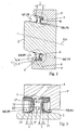
- This solution one embodiment of which is shown in Figure 1 , has two major limitations: it requires a large overall axial length, of the order of 20 mm at least (or 18.5 mm at the very least), and requires a housing with two compartments having different diameters, each adapted to one of the two seals.
- compartments of different radial sizes are not provided, it may be impossible to ensure the precise positioning of the seals, including their positioning relative to one another, or to prevent obstruction of the discharge channel.
- the object of the present invention is to overcome these drawbacks.
- a double sealing device for a rotating shaft notably for a rotating shaft or spindle of a fuel injection pump, comprising a first and a second seals of annular form, mounted side by side in a circular cylindrical housing through which the shaft to be sealed passes and into which a discharge and/or vent channel opens, in a peripheral groove formed in or associated with the wall of the housing, between the two seals, each of these seals being composed of, on the one hand, a carrier ring of metal material with an outer axial flange and an inner radial flange and, on the other hand, a sealing washer, preferably PTFE-based and applied to the corresponding carrier ring so as to cover at least a part of the outer face of its axial flange, thereby forming a seal between the latter and the wall of the housing as well as the adjacent face of the radial flange, and so as to extend beyond the free end of the radial flange to form a sealing lip bearing slidably on the shaft
- This device comprises a first 3 and a second 4 seal of annular form, mounted side by side in a circular cylindrical housing 5 through which the shaft 2 to be sealed passes and into which a discharge and/or vent channel 6 opens, in a peripheral groove 7 formed in or associated with the wall of the housing 5, between the two seals 3 and 4,
- Each of these seals 3 and 4 is composed, on the one hand, of a carrier ring 8 or 9 of metal material with an outer axial flange 8' or 9' and an inner radial flange 8" or 9" and, on the other hand, of a sealing washer 10 or 11, preferably PTFE-based and applied to the corresponding carrier ring 8 or 9 so as to cover at least a part of the outer face of its axial flange 8' or 9', thereby forming a seal between the latter and the wall of the housing 5 as well as the adjacent face of the radial flange 8" or 9", and so as to extend beyond the free end of the radial flange 8" or 9" to form a sealing lip 13 or 14 bearing slidably on the shaft 2 to be sealed.
- the first seal 3 seals off a first fluid medium MLPE from the peripheral groove 7
- the second seal 4 seals off a second fluid medium MLPF from this groove 7.
- the housing 5, receiving the two seals 3 and 4 may have a constant diameter, is formed in a casing or shell 5', and may form part of a passage through which the shaft 2 passes (this passage may if necessary include one or more bearings, which are not shown, for guiding the shaft).
- the axial flange 8', 9' of at least one of the carrier rings 8, 9 of the first and second seals 3, 4 has an extension at its free end forming a pierced or cut-out ring structure 12, not covered by the sealing washer 10, 11 of the corresponding seal 3, 4, and located substantially facing the peripheral groove 7 and pointing towards the other seal 4, 3.
- the two seals 3 and 4 are fitted side by side and tightly (preferably with slight compression) in the housing 5, and are preferably abutting in the axial direction XA, said at least one pierced or cut-out ring 12 also forming an axial separating or spacing structure between the two seals 3 and 4, while keeping the peripheral groove 7 substantially clear over its whole width.
- the two seals 3 and 4 may be positioned in a precise way as closely as possible to one another in the axial direction XA, while ensuring that the free space 5", whose width is calibrated (by the width of the ring 12), located between the two seals 3 and 4, is in fluid communication with the groove 7 (and therefore with the channel 6).
- the pierced ring 12 formed as one piece in the extension of the axial flange 8', comprises piercings 12' which are regularly spaced over the perimeter of the carrier ring 8 in question.
- the pierced ring 12 formed as one piece in the extension of the axial flange 8' of the carrier ring 8 in question, has a crenellated free edge 12".
- the two seals 3 and 4 forming the device 1 are mounted by introducing the first seal 3 into the housing 5 under pressure and moving it to the bottom of the housing across the groove 7.
- the latter is advantageously made in the form of a fitting chamfer having a small angle at the top, advantageously below 30°, and preferably of about 15°, in the direction of introduction of said seal 3.
- the two mutually adjacent components 3 and 4 of the device 1 can be precisely and repeatedly located with respect to said groove 7.
- each seal 3, 4 may be formed by a curved annular linking portion 13', 14' and an annular end portion 13", 14", most of which bears slidably on the shaft or spindle to be sealed 2, said annular end portion 13", 14" being advantageously provided with a return portion 15, 15' which is helical or in the form of a thread, or advantageously in the form of a groove with opposite sides having different inclinations or gradients, preferably with an asymmetric triangular cross-section or profile.
- one 8 of the carrier rings 8, 9, preferably that of the first seal 3 which seals off the medium MLPE under the higher pressure, and which has the extension 12 forming a pierced spacing ring, has a cross-section substantially in the form of a lower-case letter tau ( ⁇ ), with an incurved radial flange 8", the sealing washer 10 extending on the inner face of this incurved radial flange 8", pointing towards the medium MLPE under high pressure.
- the sealing lip 13 may also be made for the sealing lip 13 to have a small thickness, typically of less than 0.8 mm, and to form, in the absence of constraints, a truncoconical sleeve with a top angle preferably in the range from 40° to 80° and orientated towards the medium MLPE to be sealed off.
- This first seal 3 may, in particular, be a seal having the characteristics of the subject of French patent application no. 12 58667 in the name of the present applicant.
- one of the carrier rings 8, 9, preferably that of the second seal 4 which seals off the medium MLPF under lower pressure has an L-shape or a chevron shape in cross-section, the corresponding sealing washer 11 being applied to the outer faces of the radial flange 8" and axial flange 8', that is to say the faces on the opposite side from the medium MLPF under pressure to be sealed off.
- This second seal 4 may, in particular, be a seal having the characteristics of the subjects of French patent applications nos. 2 554 878 and 2 986 598 in the name of the present applicant.
- the double sealing device 1 can provide a sufficient seal for the two media MLPE and MLPF, while requiring only a minimal overall axial length, particularly a length of only about 10 mm.
- the invention also proposes, as shown partially in Figure 1 , an injection pump with a rotating spindle or shaft 2 extending simultaneously into a first space MLPE subjected to a high fluid pressure, namely the pressure of petrol or diesel fuel, and into a second space MLPF subjected to a lower fluid pressure, namely the pressure of oil.
- This pump is characterized in that it comprises a double sealing device 1 as described above.
Landscapes
- Engineering & Computer Science (AREA)
- General Engineering & Computer Science (AREA)
- Mechanical Engineering (AREA)
- Fuel-Injection Apparatus (AREA)
- Sealing Devices (AREA)
- Sealing With Elastic Sealing Lips (AREA)
- Sealing Of Bearings (AREA)
Abstract
Description
- The present invention relates to the field of sealing rotating shafts or spindles, and more particularly to double sealing systems for isolating two media which are different from one another and from the external environment, the two media possibly being at different pressures.
- In this context, the invention proposes a double sealing device and an injection pump comprising such a device.
- At the present time, in the aforesaid context, double sealing is typically provided by placing two seals in the housing through which the shaft passes, each seal being adapted for the corresponding medium to be sealed, the seals being positioned one after another, with a space between them, in the axial direction.
- In the case of injection pumps, double sealing is currently provided in a conventional way, using, on the one hand, a rubber ring on the oil side, and, on the other hand, a rubber or PTFE sealing ring with a "special pressure" profile on the diesel fuel side.
- The two parts are assembled head-to-tail in the different housing diameters, and a channel is machined in the housing between the two rings to discharge liquid to the outside in case of leakage. This channel also serves to maintain atmospheric pressure in this area.
- This solution, one embodiment of which is shown in
Figure 1 , has two major limitations: it requires a large overall axial length, of the order of 20 mm at least (or 18.5 mm at the very least), and requires a housing with two compartments having different diameters, each adapted to one of the two seals. - If compartments of different radial sizes are not provided, it may be impossible to ensure the precise positioning of the seals, including their positioning relative to one another, or to prevent obstruction of the discharge channel.
- The object of the present invention is to overcome these drawbacks.
- To this end, it proposes a double sealing device for a rotating shaft, notably for a rotating shaft or spindle of a fuel injection pump, comprising a first and a second seals of annular form, mounted side by side in a circular cylindrical housing through which the shaft to be sealed passes and into which a discharge and/or vent channel opens, in a peripheral groove formed in or associated with the wall of the housing, between the two seals,
each of these seals being composed of, on the one hand, a carrier ring of metal material with an outer axial flange and an inner radial flange and, on the other hand, a sealing washer, preferably PTFE-based and applied to the corresponding carrier ring so as to cover at least a part of the outer face of its axial flange, thereby forming a seal between the latter and the wall of the housing as well as the adjacent face of the radial flange, and so as to extend beyond the free end of the radial flange to form a sealing lip bearing slidably on the shaft to be sealed, the first seal keeping a first fluid medium sealed off from the peripheral groove and the second seal keeping a second fluid medium sealed off from this groove,
the double sealing device being characterized in that the axial flange of at least one of the carrier rings of the first and second seals has an extension at its free end forming a pierced or cut-out ring structure, not covered by the sealing washer of the corresponding seal, and located substantially facing the peripheral groove and pointing towards the other seal. - The invention will be more easily understood with the aid of the following detailed description, which relates to some preferred embodiments, provided by way of non-limiting example and explained with reference to the attached schematic drawings, in which:
-
Figure 2 is a partial sectional view, taken along a plane containing the median axis of the shaft to be sealed, of an injection pump or the like fitted with a double sealing device according to one embodiment of the invention; -
Figures 3 and4 are views in side elevation, and on a different scale, of the details A (Figure 3 ) and B (Figure 4 ) ofFigure 1 ; -
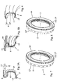
Figures 5A and 5B are partial views, in cross-section, in side elevation and in perspective, of the first seal of the device ofFigures 2 to 4 ; -
Figure 6 is a partial sectional and perspective view of the second seal of the device ofFigures 2 to 4 , and -
Figures 7 and 8 are perspective views of the two variant embodiments of the first seal of the device according to the invention. -
Figure 1 shows, andFigures 3 and4 partially show, adouble sealing device 1 for a rotatingshaft 2, notably for a rotating shaft or spindle of a fuel injection pump. - This device comprises a first 3 and a second 4 seal of annular form, mounted side by side in a circular
cylindrical housing 5 through which theshaft 2 to be sealed passes and into which a discharge and/orvent channel 6 opens, in aperipheral groove 7 formed in or associated with the wall of thehousing 5, between the twoseals - Each of these
seals carrier ring radial flange 8" or 9" and, on the other hand, of asealing washer corresponding carrier ring housing 5 as well as the adjacent face of theradial flange 8" or 9", and so as to extend beyond the free end of theradial flange 8" or 9" to form a sealinglip shaft 2 to be sealed. Thefirst seal 3 seals off a first fluid medium MLPE from theperipheral groove 7, and thesecond seal 4 seals off a second fluid medium MLPF from thisgroove 7. - As shown by
Figure 2 , thehousing 5, receiving the twoseals shaft 2 passes (this passage may if necessary include one or more bearings, which are not shown, for guiding the shaft). - According to the invention, the axial flange 8', 9' of at least one of the
carrier rings second seals ring structure 12, not covered by the sealingwasher corresponding seal peripheral groove 7 and pointing towards theother seal - Preferably, the two
seals housing 5, and are preferably abutting in the axial direction XA, said at least one pierced or cut-outring 12 also forming an axial separating or spacing structure between the twoseals peripheral groove 7 substantially clear over its whole width. - Thus the two
seals free space 5", whose width is calibrated (by the width of the ring 12), located between the twoseals - According to a first variant embodiment, shown in
Figures 2 to 5 and7 , thepierced ring 12, formed as one piece in the extension of the axial flange 8', comprisespiercings 12' which are regularly spaced over the perimeter of thecarrier ring 8 in question. - According to a second variant embodiment, shown in
Figure 8 , the piercedring 12, formed as one piece in the extension of the axial flange 8' of thecarrier ring 8 in question, has a crenellatedfree edge 12". - Preferably, and as shown in
Figures 2 to 8 , only one of the twoseals first seal 8 which seals off the medium MLPE having the higher pressure, has a pierced or cut-outspacing ring 12. - A person skilled in the art will understand that the two
seals device 1 are mounted by introducing thefirst seal 3 into thehousing 5 under pressure and moving it to the bottom of the housing across thegroove 7. - The latter is advantageously made in the form of a fitting chamfer having a small angle at the top, advantageously below 30°, and preferably of about 15°, in the direction of introduction of said
seal 3. - By using a stop to position this
first seal 3 at the end of fitting, the two mutuallyadjacent components device 1 can be precisely and repeatedly located with respect to saidgroove 7. - Additionally, since there is a constant diameter housing 5 (having the same diameter for both axial portions of the housing receiving the
first seal 3 and thesecond seal 4 respectively), no further compression is necessary when the first seal is placed in its final position (the compression that it undergoes in the first phase of its introduction, before passing over thegroove 7, is sufficient for this final placing). This greatly limits the risk of seizing of the portion of the sealingwasher 10 covering the outer face of the axial flange 8' of thering 8 of theseal 3. - It is also possible to envisage an embodiment of the invention in which no
special groove 7 is formed in the wall of thehousing 5. In fact, the interstice between thering 12 and the inner wall of the housing 5 (provided by the thickness of the portion of thecompressed washer 10 covering the axial flange 8') could provide a circular peripheral channel similar to a groove of this type, into which thepiercings 12', on one hand, and theoutflow channel 6, on the other hand, would open. - Advantageously, and in order to obtain a good dynamic seal around the
shaft 2, provision may be made for thesealing lip seal annular end portion 13", 14", most of which bears slidably on the shaft or spindle to be sealed 2, saidannular end portion 13", 14" being advantageously provided with areturn portion 15, 15' which is helical or in the form of a thread, or advantageously in the form of a groove with opposite sides having different inclinations or gradients, preferably with an asymmetric triangular cross-section or profile. - As shown, by way of example, in
Figures 3 to 5 notably, one 8 of thecarrier rings first seal 3 which seals off the medium MLPE under the higher pressure, and which has theextension 12 forming a pierced spacing ring, has a cross-section substantially in the form of a lower-case letter tau (τ), with an incurvedradial flange 8", thesealing washer 10 extending on the inner face of this incurvedradial flange 8", pointing towards the medium MLPE under high pressure. - Together with this construction of the
first seal 3, provision may also be made for thesealing lip 13 to have a small thickness, typically of less than 0.8 mm, and to form, in the absence of constraints, a truncoconical sleeve with a top angle preferably in the range from 40° to 80° and orientated towards the medium MLPE to be sealed off. - This
first seal 3 may, in particular, be a seal having the characteristics of the subject of French patent application no.12 58667 - According to another advantageous characteristic of the invention, shown notably in
Figures 3 ,4 and6 , one of thecarrier rings second seal 4 which seals off the medium MLPF under lower pressure, has an L-shape or a chevron shape in cross-section, thecorresponding sealing washer 11 being applied to the outer faces of theradial flange 8" and axial flange 8', that is to say the faces on the opposite side from the medium MLPF under pressure to be sealed off. - This
second seal 4 may, in particular, be a seal having the characteristics of the subjects of French patent applications nos.2 554 878 2 986 598 - By using the aforesaid particular two types of seals, the
double sealing device 1 according to the invention can provide a sufficient seal for the two media MLPE and MLPF, while requiring only a minimal overall axial length, particularly a length of only about 10 mm. - The invention also proposes, as shown partially in
Figure 1 , an injection pump with a rotating spindle orshaft 2 extending simultaneously into a first space MLPE subjected to a high fluid pressure, namely the pressure of petrol or diesel fuel, and into a second space MLPF subjected to a lower fluid pressure, namely the pressure of oil. - This pump is characterized in that it comprises a
double sealing device 1 as described above. - Clearly, the invention is not limited to the embodiments described and represented in the appended drawings. Modifications may be made, notably in terms of the composition of the various elements, or by substitution of equivalent methods, without thereby departing from the scope of protection of the invention.
Claims (10)
- Double sealing device for a rotating shaft, notably for a rotating shaft or spindle of a fuel injection pump, comprising a first and a second seal of annular form, mounted side by side in a circular cylindrical housing through which the shaft to be sealed passes and into which a discharge and/or vent channel opens, in a peripheral groove formed in or associated with the wall of the housing, between the two seals,
each of these seals being composed of, on the one hand, a carrier ring of metal material with an outer axial flange and an inner radial flange and, on the other hand, a sealing washer, preferably PTFE-based and applied to the corresponding carrier ring so as to cover at least a part of the outer face of its axial flange, thereby forming a seal between the latter and the wall of the housing as well as the adjacent face of the radial flange, and so as to extend beyond the free end of the radial flange to form a sealing lip bearing slidably on the shaft to be sealed, the first seal keeping a first fluid medium sealed off from the peripheral groove and the second seal keeping a second fluid medium sealed off from this groove,
the double sealing device (1) being characterized in that the axial flange (8', 9') of at least one of the carrier rings (8, 9) of the first and second seals (3, 4) has an extension at its free end forming a pierced or cut-out ring structure (12), not covered by the sealing washer (10, 11) of the corresponding seal (3, 4), and located substantially facing the peripheral groove (7) and pointing towards the other seal (4, 3). - Device according to Claim 1, characterized in that the two seals (3 and 4) are fitted side by side and tightly in the housing (5), and are preferably abutting in the axial direction (XA), said at least one pierced or cut-out ring (12) also forming an axial separating or spacing structure between the two seals (3 and 4), while keeping the peripheral groove (7) substantially clear over its whole width.
- Device according to Claim 1 or 2, characterized in that the pierced ring (12), formed as one piece in the extension of the axial flange (8'), comprises piercings (12') which are regularly spaced over the perimeter of the carrier ring (8) in question.
- Device according to Claim 1 or 2, characterized in that the cut-out ring (12), formed as one piece in the extension of the axial flange (8') of the carrier ring (8) in question, has a crenellated free edge (12").
- Device according to any of Claims 1 to 4, characterized in that only one of the two seals (8 and 9), preferably the first seal (8) which seals off the medium (MLPE) having the higher pressure, has a pierced or cut-out spacing ring (12).
- Device according to any of Claims 1 to 5, characterized in that the sealing lip (13, 14) of each seal (3, 4) is formed by a curved annular linking portion (13', 14') and an annular end portion (13", 14"), most of which bears slidably on the shaft or spindle to be sealed (2), said annular end portion (13", 14") being advantageously provided with a return portion (15, 15') which is helical or in the form of a thread, or advantageously in the form of a groove with opposite sides having different inclinations or gradients, preferably with an asymmetric triangular cross-section or profile.
- Device according to any of Claims 1 to 6, characterized in that one of the carrier rings (8, 9), preferably that of the first seal (3) which seals off the medium (MLPE) under the higher pressure, and which has the extension (12) forming a pierced spacing ring, has a cross-section substantially in the form of a lower-case letter tau (τ), with an incurved radial flange (8"), the sealing washer (10) extending on the inner face of this incurved radial flange (8"), pointing towards the medium (MLPE) under high pressure.
- Device according to Claim 7, characterized in that the sealing lip (13) has a small thickness, typically of less than 0.8 mm, and forms, in the absence of constraints, a truncoconical sleeve with a top angle preferably in the range from 40° to 80° and orientated towards the medium (MLPE) to be sealed off.
- Device according to any of Claims 1 to 8, characterized in that one of the carrier rings (8, 9), preferably that of the second seal (4) which seals off the medium MLPF under lower pressure, has an L-shape or a chevron shape in cross-section, the corresponding sealing washer (11) being applied to the outer faces of the radial flange (8") and axial flange (8'), that is to say the faces on the opposite side from the medium (MLPF) under pressure to be sealed off.
- Injection pump with a rotating spindle or shaft extending simultaneously into a first space subjected to a high fluid pressure, namely the pressure of petrol or diesel fuel, and into a second space subjected to a lower fluid pressure, namely the pressure of oil, the pump being characterized in that it comprises a double sealing device (1) according to any of Claims 1 to 9.
Applications Claiming Priority (1)
| Application Number | Priority Date | Filing Date | Title |
|---|---|---|---|
| FR1452053A FR3018575B1 (en) | 2014-03-12 | 2014-03-12 | DOUBLE SEALING DEVICE FOR ROTARY SHAFT AND PUMP COMPRISING SUCH A DEVICE |
Publications (2)
| Publication Number | Publication Date |
|---|---|
| EP2918878A1 true EP2918878A1 (en) | 2015-09-16 |
| EP2918878B1 EP2918878B1 (en) | 2017-11-22 |
Family
ID=50829151
Family Applications (1)
| Application Number | Title | Priority Date | Filing Date |
|---|---|---|---|
| EP15152981.5A Active EP2918878B1 (en) | 2014-03-12 | 2015-01-29 | Double sealing device and an injection pump comprising such a device |
Country Status (6)
| Country | Link |
|---|---|
| US (1) | US9845882B2 (en) |
| EP (1) | EP2918878B1 (en) |
| JP (1) | JP6029700B2 (en) |
| CN (1) | CN104913060B (en) |
| BR (1) | BR102015004981B1 (en) |
| FR (1) | FR3018575B1 (en) |
Cited By (2)
| Publication number | Priority date | Publication date | Assignee | Title |
|---|---|---|---|---|
| CN111156314A (en) * | 2018-11-07 | 2020-05-15 | 本田技研工业株式会社 | sealing structure |
| CN119914628A (en) * | 2025-02-28 | 2025-05-02 | 江西洪都航空工业集团有限责任公司 | A sealing protection device for self-lubricating bearing after installation |
Families Citing this family (14)
| Publication number | Priority date | Publication date | Assignee | Title |
|---|---|---|---|---|
| FR2995652B1 (en) * | 2012-09-14 | 2014-09-26 | Freudenberg Carl Kg | SEAL, ESPECIALLY FOR PRESSURIZED LIQUID |
| FR3047065A1 (en) | 2016-01-25 | 2017-07-28 | Freudenberg Carl Kg | ANGULAR DETECTION DEVICE WITH PROTECTION AGAINST EXTERNAL CONTAMINANTS |
| CN106246918A (en) * | 2016-09-14 | 2016-12-21 | 天津汇讯视通科技有限公司 | Bearing sealing structure on pan-tilt camera |
| CN108612667A (en) * | 2016-12-09 | 2018-10-02 | 镇江立中机械设备有限公司 | Wind turbine non-contact mechanical seal structure |
| DE102017004061B4 (en) * | 2017-04-27 | 2019-01-31 | Carl Freudenberg Kg | poetry |
| EP3767136B1 (en) * | 2018-03-14 | 2024-10-23 | Sealink Corp. | Rotating sealing device |
| EP3667132A1 (en) * | 2018-12-13 | 2020-06-17 | Siemens Aktiengesellschaft | Seal assembly for a split housing |
| US11105424B2 (en) * | 2019-02-01 | 2021-08-31 | Kaydon Ring & Seal, Inc. | Crowned anti-rotation device for circumferential seals |
| CN111720567B (en) * | 2020-06-10 | 2022-07-05 | 肯卓自控工程(江苏)有限公司 | Pressure balance type sleeve regulating valve core seat sealing structure |
| CN111895092B (en) * | 2020-07-01 | 2022-05-17 | 湖南双龙科技发展有限公司 | Shaft sealing device of compressor |
| CN112236006B (en) * | 2020-10-16 | 2022-10-04 | 安擎(天津)计算机有限公司 | Combined server rack structure and connecting method thereof |
| DE102021105500A1 (en) * | 2021-03-08 | 2022-09-08 | Carl Freudenberg Kg | sealing ring |
| CN115163208B (en) * | 2022-07-29 | 2025-11-21 | 中国航发沈阳发动机研究所 | Vibration damping ring for stator blade of aeroengine |
| CN115434942B (en) * | 2022-08-24 | 2024-07-05 | 宁波威孚天力增压技术股份有限公司 | Supercharger with improved sealing structure |
Citations (5)
| Publication number | Priority date | Publication date | Assignee | Title |
|---|---|---|---|---|
| FR1258667A (en) | 1960-06-02 | 1961-04-14 | Bayer Ag | Process for the continuous preparation of trialcohols and higher polyalcohols |
| FR2554878A1 (en) | 1983-11-14 | 1985-05-17 | United Technologies Corp | ISOSTATIC MATRIX AND METHOD FOR ASSEMBLING SKELETAL STRUCTURES |
| US5009435A (en) * | 1989-08-15 | 1991-04-23 | Cummins Engine Company, Inc. | Unitary sealing system with internal venting |
| US6561519B1 (en) * | 2000-11-08 | 2003-05-13 | Freudenberg-Nok General Partnership | Dual seal |
| FR2986598A1 (en) | 2012-02-03 | 2013-08-09 | Freudenberg Carl Kg | SEAL |
Family Cites Families (15)
| Publication number | Priority date | Publication date | Assignee | Title |
|---|---|---|---|---|
| US2167603A (en) * | 1936-11-06 | 1939-07-25 | Victor Mfg & Gasket Co | Grease retainer with unitary diaphragms and supports |
| US2291570A (en) * | 1940-12-27 | 1942-07-28 | Harold A Clark | Oil seal |
| US2348586A (en) * | 1942-10-10 | 1944-05-09 | Victor Mfg & Gasket Co | Oil seal |
| US3575426A (en) * | 1968-06-24 | 1971-04-20 | Caterpillar Tractor Co | Pressurized sealing arrangement |
| JPH0726164Y2 (en) * | 1989-07-28 | 1995-06-14 | 日産自動車株式会社 | Sealing device for tire pressure regulator |
| US5199718A (en) * | 1992-04-13 | 1993-04-06 | Vickers, Incorporated | Rotary machine shaft seal |
| IT1276368B1 (en) * | 1995-06-09 | 1997-10-31 | Stefa S R L | LIP SEALING COMPLEX. |
| DE10129449A1 (en) * | 2001-06-19 | 2003-01-02 | Bosch Gmbh Robert | High-pressure fuel pump for internal combustion engines with improved part-load behavior |
| US6830641B2 (en) * | 2001-08-13 | 2004-12-14 | Saint-Gobain Performance Plastics Corporation | Method of making a seal formed from polymer laminated metallic constructions |
| US6988733B2 (en) * | 2003-02-13 | 2006-01-24 | Federal-Mogul World Wide, Inc. | Bonded PTFE radial shaft seal |
| EP1612460B1 (en) * | 2003-04-07 | 2013-07-03 | Eagle Industry Co., Ltd. | Lip-type seal |
| JP2005299808A (en) * | 2004-04-13 | 2005-10-27 | Nok Corp | Seal for pump |
| DE102010001345B4 (en) * | 2010-01-28 | 2013-09-19 | Trelleborg Sealing Solutions Germany Gmbh | Rotary union |
| EP2554878B1 (en) | 2011-08-03 | 2016-07-13 | Carl Freudenberg KG | Seal |
| FR2995652B1 (en) | 2012-09-14 | 2014-09-26 | Freudenberg Carl Kg | SEAL, ESPECIALLY FOR PRESSURIZED LIQUID |
-
2014
- 2014-03-12 FR FR1452053A patent/FR3018575B1/en active Active
-
2015
- 2015-01-29 EP EP15152981.5A patent/EP2918878B1/en active Active
- 2015-03-06 BR BR102015004981-1A patent/BR102015004981B1/en active IP Right Grant
- 2015-03-11 CN CN201510105550.4A patent/CN104913060B/en active Active
- 2015-03-12 US US14/645,473 patent/US9845882B2/en active Active
- 2015-03-12 JP JP2015049099A patent/JP6029700B2/en active Active
Patent Citations (5)
| Publication number | Priority date | Publication date | Assignee | Title |
|---|---|---|---|---|
| FR1258667A (en) | 1960-06-02 | 1961-04-14 | Bayer Ag | Process for the continuous preparation of trialcohols and higher polyalcohols |
| FR2554878A1 (en) | 1983-11-14 | 1985-05-17 | United Technologies Corp | ISOSTATIC MATRIX AND METHOD FOR ASSEMBLING SKELETAL STRUCTURES |
| US5009435A (en) * | 1989-08-15 | 1991-04-23 | Cummins Engine Company, Inc. | Unitary sealing system with internal venting |
| US6561519B1 (en) * | 2000-11-08 | 2003-05-13 | Freudenberg-Nok General Partnership | Dual seal |
| FR2986598A1 (en) | 2012-02-03 | 2013-08-09 | Freudenberg Carl Kg | SEAL |
Cited By (3)
| Publication number | Priority date | Publication date | Assignee | Title |
|---|---|---|---|---|
| CN111156314A (en) * | 2018-11-07 | 2020-05-15 | 本田技研工业株式会社 | sealing structure |
| CN119914628A (en) * | 2025-02-28 | 2025-05-02 | 江西洪都航空工业集团有限责任公司 | A sealing protection device for self-lubricating bearing after installation |
| CN119914628B (en) * | 2025-02-28 | 2025-09-23 | 江西洪都航空工业集团有限责任公司 | A sealing protection device for self-lubricating bearings after installation |
Also Published As
| Publication number | Publication date |
|---|---|
| FR3018575A1 (en) | 2015-09-18 |
| JP6029700B2 (en) | 2016-11-24 |
| US9845882B2 (en) | 2017-12-19 |
| BR102015004981B1 (en) | 2022-09-27 |
| FR3018575B1 (en) | 2018-04-20 |
| CN104913060A (en) | 2015-09-16 |
| JP2015175522A (en) | 2015-10-05 |
| US20150260291A1 (en) | 2015-09-17 |
| CN104913060B (en) | 2017-12-26 |
| BR102015004981A2 (en) | 2016-05-24 |
| EP2918878B1 (en) | 2017-11-22 |
Similar Documents
| Publication | Publication Date | Title |
|---|---|---|
| EP2918878B1 (en) | Double sealing device and an injection pump comprising such a device | |
| US9862266B2 (en) | Vehicle fuel filler system seal | |
| US9388904B2 (en) | Gasket, in particular for a pressurised liquid | |
| KR20220024958A (en) | sliding parts | |
| EP3428406A3 (en) | Ring seal arrangement with installation foolproofing | |
| EP3118493A1 (en) | Sealing device | |
| EP2924325A1 (en) | Shaft seal | |
| KR20150133636A (en) | Shaft seal | |
| US11125336B2 (en) | Self energized seal | |
| KR102055319B1 (en) | Oil free screw compressor | |
| EP3070379A1 (en) | Mechanical seal | |
| EP3546775A1 (en) | Sintered bearing | |
| US8328201B2 (en) | Pumping seal assembly with angled spring | |
| US11131387B2 (en) | Sealing ring and seal arrangement comprising such a sealing ring | |
| CN100370934C (en) | Sealing structure of piston device for extracting content | |
| EP3686464A1 (en) | Mecanical seal | |
| EP2949972A8 (en) | Cassette seal | |
| CA2969760C (en) | Bearing isolator seal with enhanced rotor drive coupling | |
| EP3184865A1 (en) | Sealing structure | |
| KR20190094367A (en) | Sealing device and sealing assembly | |
| RU2588328C1 (en) | Double seal for rotary shaft and pump comprising said device | |
| US10478761B2 (en) | Filter device | |
| US20040169340A1 (en) | Seal having gaps | |
| JP2021092260A (en) | mechanical seal | |
| US20090224489A1 (en) | Oil seal |
Legal Events
| Date | Code | Title | Description |
|---|---|---|---|
| PUAI | Public reference made under article 153(3) epc to a published international application that has entered the european phase |
Free format text: ORIGINAL CODE: 0009012 |
|
| AK | Designated contracting states |
Kind code of ref document: A1 Designated state(s): AL AT BE BG CH CY CZ DE DK EE ES FI FR GB GR HR HU IE IS IT LI LT LU LV MC MK MT NL NO PL PT RO RS SE SI SK SM TR |
|
| AX | Request for extension of the european patent |
Extension state: BA ME |
|
| 17P | Request for examination filed |
Effective date: 20151217 |
|
| RBV | Designated contracting states (corrected) |
Designated state(s): AL AT BE BG CH CY CZ DE DK EE ES FI FR GB GR HR HU IE IS IT LI LT LU LV MC MK MT NL NO PL PT RO RS SE SI SK SM TR |
|
| GRAP | Despatch of communication of intention to grant a patent |
Free format text: ORIGINAL CODE: EPIDOSNIGR1 |
|
| GRAJ | Information related to disapproval of communication of intention to grant by the applicant or resumption of examination proceedings by the epo deleted |
Free format text: ORIGINAL CODE: EPIDOSDIGR1 |
|
| GRAP | Despatch of communication of intention to grant a patent |
Free format text: ORIGINAL CODE: EPIDOSNIGR1 |
|
| GRAJ | Information related to disapproval of communication of intention to grant by the applicant or resumption of examination proceedings by the epo deleted |
Free format text: ORIGINAL CODE: EPIDOSDIGR1 |
|
| INTG | Intention to grant announced |
Effective date: 20170317 |
|
| GRAP | Despatch of communication of intention to grant a patent |
Free format text: ORIGINAL CODE: EPIDOSNIGR1 |
|
| INTG | Intention to grant announced |
Effective date: 20170331 |
|
| GRAJ | Information related to disapproval of communication of intention to grant by the applicant or resumption of examination proceedings by the epo deleted |
Free format text: ORIGINAL CODE: EPIDOSDIGR1 |
|
| GRAP | Despatch of communication of intention to grant a patent |
Free format text: ORIGINAL CODE: EPIDOSNIGR1 |
|
| INTG | Intention to grant announced |
Effective date: 20170424 |
|
| INTG | Intention to grant announced |
Effective date: 20170515 |
|
| GRAJ | Information related to disapproval of communication of intention to grant by the applicant or resumption of examination proceedings by the epo deleted |
Free format text: ORIGINAL CODE: EPIDOSDIGR1 |
|
| GRAP | Despatch of communication of intention to grant a patent |
Free format text: ORIGINAL CODE: EPIDOSNIGR1 |
|
| GRAJ | Information related to disapproval of communication of intention to grant by the applicant or resumption of examination proceedings by the epo deleted |
Free format text: ORIGINAL CODE: EPIDOSDIGR1 |
|
| GRAP | Despatch of communication of intention to grant a patent |
Free format text: ORIGINAL CODE: EPIDOSNIGR1 |
|
| INTG | Intention to grant announced |
Effective date: 20170620 |
|
| INTC | Intention to grant announced (deleted) | ||
| INTG | Intention to grant announced |
Effective date: 20170707 |
|
| GRAS | Grant fee paid |
Free format text: ORIGINAL CODE: EPIDOSNIGR3 |
|
| GRAA | (expected) grant |
Free format text: ORIGINAL CODE: 0009210 |
|
| AK | Designated contracting states |
Kind code of ref document: B1 Designated state(s): AL AT BE BG CH CY CZ DE DK EE ES FI FR GB GR HR HU IE IS IT LI LT LU LV MC MK MT NL NO PL PT RO RS SE SI SK SM TR |
|
| REG | Reference to a national code |
Ref country code: GB Ref legal event code: FG4D |
|
| REG | Reference to a national code |
Ref country code: CH Ref legal event code: EP |
|
| REG | Reference to a national code |
Ref country code: IE Ref legal event code: FG4D |
|
| REG | Reference to a national code |
Ref country code: AT Ref legal event code: REF Ref document number: 948724 Country of ref document: AT Kind code of ref document: T Effective date: 20171215 |
|
| REG | Reference to a national code |
Ref country code: DE Ref legal event code: R096 Ref document number: 602015006087 Country of ref document: DE |
|
| REG | Reference to a national code |
Ref country code: FR Ref legal event code: PLFP Year of fee payment: 4 |
|
| REG | Reference to a national code |
Ref country code: NL Ref legal event code: MP Effective date: 20171122 |
|
| REG | Reference to a national code |
Ref country code: LT Ref legal event code: MG4D |
|
| REG | Reference to a national code |
Ref country code: AT Ref legal event code: MK05 Ref document number: 948724 Country of ref document: AT Kind code of ref document: T Effective date: 20171122 |
|
| PG25 | Lapsed in a contracting state [announced via postgrant information from national office to epo] |
Ref country code: ES Free format text: LAPSE BECAUSE OF FAILURE TO SUBMIT A TRANSLATION OF THE DESCRIPTION OR TO PAY THE FEE WITHIN THE PRESCRIBED TIME-LIMIT Effective date: 20171122 Ref country code: LT Free format text: LAPSE BECAUSE OF FAILURE TO SUBMIT A TRANSLATION OF THE DESCRIPTION OR TO PAY THE FEE WITHIN THE PRESCRIBED TIME-LIMIT Effective date: 20171122 Ref country code: NL Free format text: LAPSE BECAUSE OF FAILURE TO SUBMIT A TRANSLATION OF THE DESCRIPTION OR TO PAY THE FEE WITHIN THE PRESCRIBED TIME-LIMIT Effective date: 20171122 Ref country code: FI Free format text: LAPSE BECAUSE OF FAILURE TO SUBMIT A TRANSLATION OF THE DESCRIPTION OR TO PAY THE FEE WITHIN THE PRESCRIBED TIME-LIMIT Effective date: 20171122 Ref country code: NO Free format text: LAPSE BECAUSE OF FAILURE TO SUBMIT A TRANSLATION OF THE DESCRIPTION OR TO PAY THE FEE WITHIN THE PRESCRIBED TIME-LIMIT Effective date: 20180222 Ref country code: SE Free format text: LAPSE BECAUSE OF FAILURE TO SUBMIT A TRANSLATION OF THE DESCRIPTION OR TO PAY THE FEE WITHIN THE PRESCRIBED TIME-LIMIT Effective date: 20171122 |
|
| PG25 | Lapsed in a contracting state [announced via postgrant information from national office to epo] |
Ref country code: HR Free format text: LAPSE BECAUSE OF FAILURE TO SUBMIT A TRANSLATION OF THE DESCRIPTION OR TO PAY THE FEE WITHIN THE PRESCRIBED TIME-LIMIT Effective date: 20171122 Ref country code: BG Free format text: LAPSE BECAUSE OF FAILURE TO SUBMIT A TRANSLATION OF THE DESCRIPTION OR TO PAY THE FEE WITHIN THE PRESCRIBED TIME-LIMIT Effective date: 20180222 Ref country code: GR Free format text: LAPSE BECAUSE OF FAILURE TO SUBMIT A TRANSLATION OF THE DESCRIPTION OR TO PAY THE FEE WITHIN THE PRESCRIBED TIME-LIMIT Effective date: 20180223 Ref country code: LV Free format text: LAPSE BECAUSE OF FAILURE TO SUBMIT A TRANSLATION OF THE DESCRIPTION OR TO PAY THE FEE WITHIN THE PRESCRIBED TIME-LIMIT Effective date: 20171122 Ref country code: AT Free format text: LAPSE BECAUSE OF FAILURE TO SUBMIT A TRANSLATION OF THE DESCRIPTION OR TO PAY THE FEE WITHIN THE PRESCRIBED TIME-LIMIT Effective date: 20171122 Ref country code: RS Free format text: LAPSE BECAUSE OF FAILURE TO SUBMIT A TRANSLATION OF THE DESCRIPTION OR TO PAY THE FEE WITHIN THE PRESCRIBED TIME-LIMIT Effective date: 20171122 |
|
| PG25 | Lapsed in a contracting state [announced via postgrant information from national office to epo] |
Ref country code: SK Free format text: LAPSE BECAUSE OF FAILURE TO SUBMIT A TRANSLATION OF THE DESCRIPTION OR TO PAY THE FEE WITHIN THE PRESCRIBED TIME-LIMIT Effective date: 20171122 Ref country code: EE Free format text: LAPSE BECAUSE OF FAILURE TO SUBMIT A TRANSLATION OF THE DESCRIPTION OR TO PAY THE FEE WITHIN THE PRESCRIBED TIME-LIMIT Effective date: 20171122 Ref country code: CY Free format text: LAPSE BECAUSE OF FAILURE TO SUBMIT A TRANSLATION OF THE DESCRIPTION OR TO PAY THE FEE WITHIN THE PRESCRIBED TIME-LIMIT Effective date: 20171122 Ref country code: CZ Free format text: LAPSE BECAUSE OF FAILURE TO SUBMIT A TRANSLATION OF THE DESCRIPTION OR TO PAY THE FEE WITHIN THE PRESCRIBED TIME-LIMIT Effective date: 20171122 Ref country code: DK Free format text: LAPSE BECAUSE OF FAILURE TO SUBMIT A TRANSLATION OF THE DESCRIPTION OR TO PAY THE FEE WITHIN THE PRESCRIBED TIME-LIMIT Effective date: 20171122 |
|
| REG | Reference to a national code |
Ref country code: DE Ref legal event code: R097 Ref document number: 602015006087 Country of ref document: DE |
|
| PG25 | Lapsed in a contracting state [announced via postgrant information from national office to epo] |
Ref country code: PL Free format text: LAPSE BECAUSE OF FAILURE TO SUBMIT A TRANSLATION OF THE DESCRIPTION OR TO PAY THE FEE WITHIN THE PRESCRIBED TIME-LIMIT Effective date: 20171122 Ref country code: IT Free format text: LAPSE BECAUSE OF FAILURE TO SUBMIT A TRANSLATION OF THE DESCRIPTION OR TO PAY THE FEE WITHIN THE PRESCRIBED TIME-LIMIT Effective date: 20171122 Ref country code: SM Free format text: LAPSE BECAUSE OF FAILURE TO SUBMIT A TRANSLATION OF THE DESCRIPTION OR TO PAY THE FEE WITHIN THE PRESCRIBED TIME-LIMIT Effective date: 20171122 Ref country code: RO Free format text: LAPSE BECAUSE OF FAILURE TO SUBMIT A TRANSLATION OF THE DESCRIPTION OR TO PAY THE FEE WITHIN THE PRESCRIBED TIME-LIMIT Effective date: 20171122 |
|
| REG | Reference to a national code |
Ref country code: CH Ref legal event code: PL |
|
| PLBE | No opposition filed within time limit |
Free format text: ORIGINAL CODE: 0009261 |
|
| STAA | Information on the status of an ep patent application or granted ep patent |
Free format text: STATUS: NO OPPOSITION FILED WITHIN TIME LIMIT |
|
| 26N | No opposition filed |
Effective date: 20180823 |
|
| PG25 | Lapsed in a contracting state [announced via postgrant information from national office to epo] |
Ref country code: LU Free format text: LAPSE BECAUSE OF NON-PAYMENT OF DUE FEES Effective date: 20180129 |
|
| REG | Reference to a national code |
Ref country code: IE Ref legal event code: MM4A |
|
| REG | Reference to a national code |
Ref country code: BE Ref legal event code: MM Effective date: 20180131 |
|
| PG25 | Lapsed in a contracting state [announced via postgrant information from national office to epo] |
Ref country code: LI Free format text: LAPSE BECAUSE OF NON-PAYMENT OF DUE FEES Effective date: 20180131 Ref country code: SI Free format text: LAPSE BECAUSE OF FAILURE TO SUBMIT A TRANSLATION OF THE DESCRIPTION OR TO PAY THE FEE WITHIN THE PRESCRIBED TIME-LIMIT Effective date: 20171122 Ref country code: BE Free format text: LAPSE BECAUSE OF NON-PAYMENT OF DUE FEES Effective date: 20180131 Ref country code: CH Free format text: LAPSE BECAUSE OF NON-PAYMENT OF DUE FEES Effective date: 20180131 |
|
| PG25 | Lapsed in a contracting state [announced via postgrant information from national office to epo] |
Ref country code: IE Free format text: LAPSE BECAUSE OF NON-PAYMENT OF DUE FEES Effective date: 20180129 |
|
| PG25 | Lapsed in a contracting state [announced via postgrant information from national office to epo] |
Ref country code: MC Free format text: LAPSE BECAUSE OF FAILURE TO SUBMIT A TRANSLATION OF THE DESCRIPTION OR TO PAY THE FEE WITHIN THE PRESCRIBED TIME-LIMIT Effective date: 20171122 |
|
| GBPC | Gb: european patent ceased through non-payment of renewal fee |
Effective date: 20190129 |
|
| PG25 | Lapsed in a contracting state [announced via postgrant information from national office to epo] |
Ref country code: GB Free format text: LAPSE BECAUSE OF NON-PAYMENT OF DUE FEES Effective date: 20190129 |
|
| PG25 | Lapsed in a contracting state [announced via postgrant information from national office to epo] |
Ref country code: MT Free format text: LAPSE BECAUSE OF NON-PAYMENT OF DUE FEES Effective date: 20180129 |
|
| PG25 | Lapsed in a contracting state [announced via postgrant information from national office to epo] |
Ref country code: TR Free format text: LAPSE BECAUSE OF FAILURE TO SUBMIT A TRANSLATION OF THE DESCRIPTION OR TO PAY THE FEE WITHIN THE PRESCRIBED TIME-LIMIT Effective date: 20171122 |
|
| PG25 | Lapsed in a contracting state [announced via postgrant information from national office to epo] |
Ref country code: PT Free format text: LAPSE BECAUSE OF FAILURE TO SUBMIT A TRANSLATION OF THE DESCRIPTION OR TO PAY THE FEE WITHIN THE PRESCRIBED TIME-LIMIT Effective date: 20171122 |
|
| PG25 | Lapsed in a contracting state [announced via postgrant information from national office to epo] |
Ref country code: MK Free format text: LAPSE BECAUSE OF NON-PAYMENT OF DUE FEES Effective date: 20171122 Ref country code: HU Free format text: LAPSE BECAUSE OF FAILURE TO SUBMIT A TRANSLATION OF THE DESCRIPTION OR TO PAY THE FEE WITHIN THE PRESCRIBED TIME-LIMIT; INVALID AB INITIO Effective date: 20150129 |
|
| PG25 | Lapsed in a contracting state [announced via postgrant information from national office to epo] |
Ref country code: AL Free format text: LAPSE BECAUSE OF FAILURE TO SUBMIT A TRANSLATION OF THE DESCRIPTION OR TO PAY THE FEE WITHIN THE PRESCRIBED TIME-LIMIT Effective date: 20171122 Ref country code: IS Free format text: LAPSE BECAUSE OF FAILURE TO SUBMIT A TRANSLATION OF THE DESCRIPTION OR TO PAY THE FEE WITHIN THE PRESCRIBED TIME-LIMIT Effective date: 20180322 |
|
| PGFP | Annual fee paid to national office [announced via postgrant information from national office to epo] |
Ref country code: DE Payment date: 20260127 Year of fee payment: 12 |
|
| PGFP | Annual fee paid to national office [announced via postgrant information from national office to epo] |
Ref country code: FR Payment date: 20260126 Year of fee payment: 12 |