EP2918841A1 - Scroll compressor - Google Patents
Scroll compressor Download PDFInfo
- Publication number
- EP2918841A1 EP2918841A1 EP13856394.5A EP13856394A EP2918841A1 EP 2918841 A1 EP2918841 A1 EP 2918841A1 EP 13856394 A EP13856394 A EP 13856394A EP 2918841 A1 EP2918841 A1 EP 2918841A1
- Authority
- EP
- European Patent Office
- Prior art keywords
- port part
- scroll
- refrigerant
- opening area
- upstream
- Prior art date
- Legal status (The legal status is an assumption and is not a legal conclusion. Google has not performed a legal analysis and makes no representation as to the accuracy of the status listed.)
- Withdrawn
Links
- 239000003507 refrigerant Substances 0.000 claims abstract description 48
- 238000011144 upstream manufacturing Methods 0.000 claims abstract description 37
- 230000006835 compression Effects 0.000 claims abstract description 25
- 238000007906 compression Methods 0.000 claims abstract description 25
- 238000007599 discharging Methods 0.000 claims abstract description 3
- 239000000203 mixture Substances 0.000 abstract description 11
- 230000002093 peripheral effect Effects 0.000 description 8
- 230000000694 effects Effects 0.000 description 5
- 230000010349 pulsation Effects 0.000 description 3
- 238000004378 air conditioning Methods 0.000 description 2
- 230000000630 rising effect Effects 0.000 description 2
- 230000003247 decreasing effect Effects 0.000 description 1
- 230000007613 environmental effect Effects 0.000 description 1
- 230000005284 excitation Effects 0.000 description 1
- 230000013011 mating Effects 0.000 description 1
- 230000003389 potentiating effect Effects 0.000 description 1
- 238000005057 refrigeration Methods 0.000 description 1
- 238000004088 simulation Methods 0.000 description 1
- 239000013585 weight reducing agent Substances 0.000 description 1
- 238000004804 winding Methods 0.000 description 1
Images



Classifications
-
- F—MECHANICAL ENGINEERING; LIGHTING; HEATING; WEAPONS; BLASTING
- F04—POSITIVE - DISPLACEMENT MACHINES FOR LIQUIDS; PUMPS FOR LIQUIDS OR ELASTIC FLUIDS
- F04C—ROTARY-PISTON, OR OSCILLATING-PISTON, POSITIVE-DISPLACEMENT MACHINES FOR LIQUIDS; ROTARY-PISTON, OR OSCILLATING-PISTON, POSITIVE-DISPLACEMENT PUMPS
- F04C29/00—Component parts, details or accessories of pumps or pumping installations, not provided for in groups F04C18/00 - F04C28/00
- F04C29/12—Arrangements for admission or discharge of the working fluid, e.g. constructional features of the inlet or outlet
-
- F—MECHANICAL ENGINEERING; LIGHTING; HEATING; WEAPONS; BLASTING
- F04—POSITIVE - DISPLACEMENT MACHINES FOR LIQUIDS; PUMPS FOR LIQUIDS OR ELASTIC FLUIDS
- F04C—ROTARY-PISTON, OR OSCILLATING-PISTON, POSITIVE-DISPLACEMENT MACHINES FOR LIQUIDS; ROTARY-PISTON, OR OSCILLATING-PISTON, POSITIVE-DISPLACEMENT PUMPS
- F04C18/00—Rotary-piston pumps specially adapted for elastic fluids
- F04C18/02—Rotary-piston pumps specially adapted for elastic fluids of arcuate-engagement type, i.e. with circular translatory movement of co-operating members, each member having the same number of teeth or tooth-equivalents
- F04C18/0207—Rotary-piston pumps specially adapted for elastic fluids of arcuate-engagement type, i.e. with circular translatory movement of co-operating members, each member having the same number of teeth or tooth-equivalents both members having co-operating elements in spiral form
- F04C18/0215—Rotary-piston pumps specially adapted for elastic fluids of arcuate-engagement type, i.e. with circular translatory movement of co-operating members, each member having the same number of teeth or tooth-equivalents both members having co-operating elements in spiral form where only one member is moving
-
- F—MECHANICAL ENGINEERING; LIGHTING; HEATING; WEAPONS; BLASTING
- F04—POSITIVE - DISPLACEMENT MACHINES FOR LIQUIDS; PUMPS FOR LIQUIDS OR ELASTIC FLUIDS
- F04C—ROTARY-PISTON, OR OSCILLATING-PISTON, POSITIVE-DISPLACEMENT MACHINES FOR LIQUIDS; ROTARY-PISTON, OR OSCILLATING-PISTON, POSITIVE-DISPLACEMENT PUMPS
- F04C18/00—Rotary-piston pumps specially adapted for elastic fluids
- F04C18/02—Rotary-piston pumps specially adapted for elastic fluids of arcuate-engagement type, i.e. with circular translatory movement of co-operating members, each member having the same number of teeth or tooth-equivalents
- F04C18/0207—Rotary-piston pumps specially adapted for elastic fluids of arcuate-engagement type, i.e. with circular translatory movement of co-operating members, each member having the same number of teeth or tooth-equivalents both members having co-operating elements in spiral form
- F04C18/0246—Details concerning the involute wraps or their base, e.g. geometry
- F04C18/0253—Details concerning the base
- F04C18/0261—Details of the ports, e.g. location, number, geometry
-
- F—MECHANICAL ENGINEERING; LIGHTING; HEATING; WEAPONS; BLASTING
- F04—POSITIVE - DISPLACEMENT MACHINES FOR LIQUIDS; PUMPS FOR LIQUIDS OR ELASTIC FLUIDS
- F04C—ROTARY-PISTON, OR OSCILLATING-PISTON, POSITIVE-DISPLACEMENT MACHINES FOR LIQUIDS; ROTARY-PISTON, OR OSCILLATING-PISTON, POSITIVE-DISPLACEMENT PUMPS
- F04C2250/00—Geometry
- F04C2250/10—Geometry of the inlet or outlet
- F04C2250/102—Geometry of the inlet or outlet of the outlet
-
- F—MECHANICAL ENGINEERING; LIGHTING; HEATING; WEAPONS; BLASTING
- F04—POSITIVE - DISPLACEMENT MACHINES FOR LIQUIDS; PUMPS FOR LIQUIDS OR ELASTIC FLUIDS
- F04C—ROTARY-PISTON, OR OSCILLATING-PISTON, POSITIVE-DISPLACEMENT MACHINES FOR LIQUIDS; ROTARY-PISTON, OR OSCILLATING-PISTON, POSITIVE-DISPLACEMENT PUMPS
- F04C2270/00—Control; Monitoring or safety arrangements
- F04C2270/13—Noise
-
- F—MECHANICAL ENGINEERING; LIGHTING; HEATING; WEAPONS; BLASTING
- F04—POSITIVE - DISPLACEMENT MACHINES FOR LIQUIDS; PUMPS FOR LIQUIDS OR ELASTIC FLUIDS
- F04C—ROTARY-PISTON, OR OSCILLATING-PISTON, POSITIVE-DISPLACEMENT MACHINES FOR LIQUIDS; ROTARY-PISTON, OR OSCILLATING-PISTON, POSITIVE-DISPLACEMENT PUMPS
- F04C23/00—Combinations of two or more pumps, each being of rotary-piston or oscillating-piston type, specially adapted for elastic fluids; Pumping installations specially adapted for elastic fluids; Multi-stage pumps specially adapted for elastic fluids
- F04C23/008—Hermetic pumps
Definitions
- the present invention relates to a scroll compressor which is included, for example, in an indoor air conditioning device.
- a scroll compressor which is used for a refrigeration cycle of an air conditioning device, a refrigerating device, etc. includes a fixed scroll and a turning scroll.
- Each of the fixed scroll and the turning scroll is a spiral wrap wall integrally formed on one surface side of a disc-shaped end plate.
- Such fixed scroll and turning scroll are opposed to each other with their wrap walls meshed, and the turning scroll is set in a revolving turning motion relative to the fixed scroll by means of an electric motor etc.
- a compression chamber formed between both wrap walls is moved from the outer peripheral side to the inner peripheral side while being reduced in volume, and thereby a refrigerant gas inside the compression chamber is compressed.
- the refrigerant gas compressed in the compression chamber passes through a discharge port, which is formed in the end plate of the fixed scroll, flows into a high-pressure chamber between a discharge cover and a housing, and is discharged toward a refrigerant circuit from a discharge pipe provided in the housing.
- Patent Literature 1 proposes that a diffuser should be formed in the discharge port in order to reduce pressure loss and improve mechanical efficiency.
- Patent Literature 2 proposes a muffler chamber, which is open in the upper surface of the end plate of the fixed scroll and communicates with the discharge port of the fixed scroll, in order to realize noise reduction of the compressor stably over a long period of time.
- refrigerant mixtures such as R410C (pseudo-azeotropic refrigerant mixture) and R407C (zeotropic refrigerant mixture) are being increasingly used. It was confirmed that, when a refrigerant mixture is used, components in the range of 1 k to 2 kHz of discharge pulsation at the discharge port of the fixed scroll are generated as noise. According to a review by the present inventors, Patent Literature 1 and Patent Literature 2 do not provide a solution for this noise.
- the present invention aims to provide a scroll compressor which can reduce noise in a specific frequency range caused when a refrigerant mixture is used.
- the present inventors have conducted studies to achieve the above object, and concluded that the relation between the acoustic velocity of a refrigerant mixture and the distance of a refrigerant passage including the discharge port plays a role in noise generation.
- the acoustic velocity of a refrigerant mixture such as R410A or 407C at the discharge port is about 160 to 180 m/s.
- the fixed scroll end plate thickness L1 is assumed to be 10 to 20 mm and the scroll height L2 is assumed to be 10 to 20 mm.
- L1 corresponds to the length of the discharge port formed in the fixed scroll end plate
- L2 corresponds to the length of the compression chamber formed by the fixed scroll and the turning scroll, so that L represents the distance of the refrigerant passage stretching from the compression chamber to the discharge port.
- the acoustic eigenvalue (f) 1 to 2 kHz is obtained. Discharge pulsation resonating in this frequency range is likely to lead to resonate with other structural members of the scroll compressor and a structure surrounding the scroll compressor (hereinafter collectively referred to as a structure), so that the noise from the compressor is amplified.
- the present inventors have focused on adjusting the acoustic eigenvalue so as to avoid resonance with the structure, which is how the present invention has been completed.
- a scroll compressor of the present invention includes: a turning scroll which is rotatably coupled with an eccentric shaft part of a main shaft; and a fixed scroll which is opposed to the turning scroll to thereby form a compression chamber for compressing a refrigerant and has an end plate in which a discharge port for discharging the compressed refrigerant toward a high-pressure chamber is formed, wherein the discharge port is composed of an upstream port part which continues to the compression chamber and has an opening area A1 and a downstream port part which continues to the upstream port part and has an opening area A2 larger than the opening area A1 of the upstream port part, and a node of a vibration mode is generated at the border between the upstream port part and the downstream port part.
- a node of a vibration mode is generated at the border between the upstream port part and the downstream port part by differentiating the opening areas of the upstream port part and the downstream port part from each other.
- the upstream port part corresponds to the portion L1 described above.
- the discharge port in the present invention includes several forms.
- the opening area A2 can be uniform, or enlarged stepwise or continuously, in a flow direction of the refrigerant.
- a circular port with a uniform diameter is preferable in view of ease of processing.
- the scroll compressor of the present invention can reduce noise in a specific frequency range caused when a refrigerant mixture is used.
- a scroll compressor 1 of this embodiment includes, inside a housing 10, an electric motor 12 and a scroll compression mechanism 2 driven by the electric motor 12.
- This scroll compressor 1 compresses a refrigerant such as R410C or R407C and supplies it to a refrigerant circuit of an air conditioner or a refrigerator, for example.
- the housing 10 includes a cylindrical closed-end housing main body 101 with an open upper end and a housing top 102 covering the opening at the upper end of the housing main body 101.
- a suction pipe 13 which introduces a refrigerant from an accumulator (not shown) into the housing main body 101 is provided.
- a discharge pipe 14 which discharges a refrigerant compressed by the scroll compression mechanism 2 is provided on the housing top 102.
- the inside of the housing 10 is partitioned by a discharge cover 25 into a low-pressure chamber 10A and a high-pressure chamber 10B.
- the electric motor 12 includes a stator 15 and a rotor 16.
- the stator 15 is provided with a winding which generates a magnetic field as power is supplied to it through a power source unit (not shown) mounted on the side surface of the housing main body 101.
- the rotor 16 includes a permanent magnet and a yoke as main components, and further has a main shaft 17 integrally connected at the center.
- An upper bearing 18 and a lower bearing 19 which rotatably support the main shaft 17 are provided on both end sides of the main shaft 17 across the electric motor 12.
- an eccentric pin 17A provided at the upper end of the main shaft 17 protrudes and is housed.
- the scroll compression mechanism 2 includes a fixed scroll 20 and a turning scroll 30 which makes a revolving turning motion relative to the fixed scroll 20.
- the fixed scroll 20 includes a fixed end plate 21 and a spiral wrap 22 rising from one surface of the fixed end plate 21.
- the fixed scroll 20 also includes a discharge port 23 in the fixed end plate 21.
- the discharge port 23 passes through the fixed end plate 21 from one surface to the other surface, and has one end (the lower side in the drawing) open toward a compression chamber PR formed between the fixed scroll 20 and the turning scroll 30 and the other end (the upper side in the drawing) open toward a discharge port 27 of the discharge cover 25 covering the upper side of the fixed scroll 20.
- the discharge port 23 is composed of an upstream port part 23A located on the upstream side with reference to a flow direction F of the refrigerant ( FIG. 2A ) and a downstream port part 23B located on the downstream side from the upstream port part 23A.
- the upstream port part 23A continues to the compression chamber PR, while the downstream port part 23B continues to the upstream port part 23A.
- the upstream port part 23A has a circular opening, and the opening area is denoted by A1.
- the downstream port part 23B has a fan-shaped opening, and the opening area is denoted by A2.
- the opening area A2 of the downstream port part 23B is larger than the opening area A1 of the upstream port part 23A.
- the turning scroll 30 includes a disc-shaped turning end plate 31 and a spiral wrap 32 rising from one surface of the turning end plate 31.
- a boss 34 is provided on the back surface of the turning end plate 31 of the turning scroll 30, a boss 34 is provided and a drive bush 36 is installed in the boss 34 through the bearing.
- the eccentric pin 17A is fitted inside the drive bush 36.
- An Oldham ring (not shown) which restricts rotation is provided between the turning scroll 30 and the main shaft 17 so that the turning scroll 30 revolves without rotating.
- the wraps 22, 32 which are eccentric to each other by a predetermined amount and meshed 180 degrees out of phase, come into contact with each other at a plurality of positions according to the rotation angle of the turning scroll 30. Then, the compression chamber PR is formed in point symmetry relative to a central part (most inner peripheral part) of the spiral of the wraps 22, 32, and the compression chamber is moved gradually toward the inner peripheral side while decreasing in volume as the turning scroll 30 turns. The refrigerant is compressed maximally in the central part of the spiral.
- the compression chamber PR of FIG. 1 is shown in this part.
- the volume of the compression chamber PR formed between both scrolls 20, 30 is reduced also in the height direction of the wrap in the course of the spiral.
- the wrap height is lower on the inner peripheral side than on the outer peripheral side, and the end plate of the mating scroll opposite to this stepped wrap protrudes further toward the inner surface side of the end plate on the inner peripheral side than on the outer peripheral side.
- the electric motor 12 is excited and a refrigerant is introduced through the suction pipe 13 into the housing 10.
- the main shaft 17 rotates and accordingly the turning scroll 30 makes a revolving turning motion relative to the fixed scroll 20.
- the refrigerant is compressed in the compression chamber PR between the turning scroll 30 and the fixed scroll 20, and the refrigerant introduced into the low-pressure chamber 10A inside the housing 10 from the suction pipe 13 is suctioned to a space between the turning scroll 30 and the fixed scroll 20.
- the refrigerant compressed inside the compression chamber PR passes sequentially through the discharge port 23 of the fixed end plate 21 and the discharge port 27 of the discharge cover 25 to be discharged into the high-pressure chamber 10B, and is further discharged from the discharge pipe 14 to the outside. In this way, the refrigerant is continuously suctioned, compressed, and discharged.
- the discharge port 23 of the fixed scroll 20 is composed of the above-described upstream port part 23A and downstream port part 23B, and the opening area A2 of the downstream port part 23B is larger than the opening area A1 of the upstream port part 23A, and moreover, a node of a vibration mode is generated at the border between the upstream port part 23A and the downstream port part 23B.
- a conventional discharge port 123 with a constant opening area shown in FIG. 3B will be described. It is assumed that this opening area is A1, which is the same as that of the upstream port part 23A of this embodiment. That is, the discharge port 123 is equivalent of the upstream port part 23A of this embodiment extending to the terminal end on the downstream side.
- the wavelength ⁇ in the formula (1) below is specified by the total value of L1', L2', and L3' defined below.
- the vibration mode is continuous between a passage C1' and a passage C2', but in a passage C3', a node of a vibration mode is generated at the border with the passage C1 and the passage C2 on the upstream side.
- the acoustic velocity of a refrigerant mixture such as R410A or 407C in a refrigerant passage is about 160 to 180 m/s
- the fixed end plate thickness (L2') is assumed to be 10 to 20 mm
- the scroll height (L1') is assumed to be 10 to 20 mm
- this can result in resonating with the structure.
- the opening of the discharge port 23 is significantly expanded from the middle such that a node of a vibration mode is generated between the refrigerant passage (C1, C2) up to the upstream port part 23A and the refrigerant passage (C3) on the downstream side from the downstream port part 23B.
- the length L corresponding to the conventional length L' is reduced, the acoustic eigenvalue (f) can be increased, so that resonance with the structure can be avoided.
- the downstream port part 23B is formed from a position of a quarter of the thickness of the fixed end plate 21, the acoustic eigenvalue (f) is 1.6 to 3.2 kHz.
- the length L can be reduced by reducing the thickness of the fixed end plate 21.
- the thickness of the fixed end plate 21 cannot always be reduced.
- the configuration of the discharge port 23 of this embodiment is potent means for avoiding resonance with the structure without reducing the thickness of the fixed end plate 21.
- enlarging the opening area of the downstream port part 23B as in the discharge port 23 can reduce the pressure loss of a refrigerant in this portion, which can also contribute to performance improvement of the scroll compressor 1.
- the opening area A2 of the downstream port part 23B is set such that a node of a vibration mode is generated in connection with the opening area A1 of the upstream port part 23A.
- the length L2 of the upstream port 23A is set, with vibration of the surrounding structure taken into account, such that the acoustic eigenvalue (f) at which resonance with the structure can be avoided is obtained. Both values can be obtained by performing a vibration test through simulation.
- the downstream port part 23B of which the opening area is constant in the flow direction of the refrigerant has been shown.
- the present invention is not limited to this example.
- the downstream port part 23B may be enlarged stepwise as shown in FIG. 4A , or the downstream port part 23B may be enlarged continuously as shown in FIG. 4B .
- the upstream port part 23A may also be varied in opening area stepwise or continuously.
- downstream port part 23B has a fan-shaped opening
- the present invention is not limited to this example, and the downstream port part 23B may have another opening shape, for example, a circular shape.
- the opening shape of the downstream port part 23B is arbitrary and not limited to the fan shape.
Landscapes
- Engineering & Computer Science (AREA)
- Mechanical Engineering (AREA)
- General Engineering & Computer Science (AREA)
- Rotary Pumps (AREA)
- Applications Or Details Of Rotary Compressors (AREA)
Abstract
Description
- The present invention relates to a scroll compressor which is included, for example, in an indoor air conditioning device.
- A scroll compressor which is used for a refrigeration cycle of an air conditioning device, a refrigerating device, etc. includes a fixed scroll and a turning scroll. Each of the fixed scroll and the turning scroll is a spiral wrap wall integrally formed on one surface side of a disc-shaped end plate. Such fixed scroll and turning scroll are opposed to each other with their wrap walls meshed, and the turning scroll is set in a revolving turning motion relative to the fixed scroll by means of an electric motor etc. Thus, a compression chamber formed between both wrap walls is moved from the outer peripheral side to the inner peripheral side while being reduced in volume, and thereby a refrigerant gas inside the compression chamber is compressed.
- The refrigerant gas compressed in the compression chamber passes through a discharge port, which is formed in the end plate of the fixed scroll, flows into a high-pressure chamber between a discharge cover and a housing, and is discharged toward a refrigerant circuit from a discharge pipe provided in the housing.
- There are various proposals on the discharge port formed in the fixed scroll, since it has an influence on the performance or noise of the scroll compressor.
- For example, Patent Literature 1 proposes that a diffuser should be formed in the discharge port in order to reduce pressure loss and improve mechanical efficiency.
Patent Literature 2 proposes a muffler chamber, which is open in the upper surface of the end plate of the fixed scroll and communicates with the discharge port of the fixed scroll, in order to realize noise reduction of the compressor stably over a long period of time. -
- Patent Literature 1: Japanese Patent Laid-Open No.
H6-66271 - Patent Literature 2: Japanese Patent Laid-Open No.
2012-122376 - In order to relieve an environmental burden, refrigerant mixtures such as R410C (pseudo-azeotropic refrigerant mixture) and R407C (zeotropic refrigerant mixture) are being increasingly used. It was confirmed that, when a refrigerant mixture is used, components in the range of 1 k to 2 kHz of discharge pulsation at the discharge port of the fixed scroll are generated as noise. According to a review by the present inventors, Patent Literature 1 and
Patent Literature 2 do not provide a solution for this noise. - Having been devised on the basis of this technical problem, the present invention aims to provide a scroll compressor which can reduce noise in a specific frequency range caused when a refrigerant mixture is used.
- The present inventors have conducted studies to achieve the above object, and concluded that the relation between the acoustic velocity of a refrigerant mixture and the distance of a refrigerant passage including the discharge port plays a role in noise generation.
- In the formula (1) related to acoustic velocity, when boundary conditions are taken into account, λ=4L (L: L1 (fixed scroll end plate thickness) +L1 (scroll height)).

where c: acoustic velocity (mm/s), f: frequency (kHz), and λ: wavelength (4L) - The acoustic velocity of a refrigerant mixture such as R410A or 407C at the discharge port is about 160 to 180 m/s. The fixed scroll end plate thickness L1 is assumed to be 10 to 20 mm and the scroll height L2 is assumed to be 10 to 20 mm. Here, L1 corresponds to the length of the discharge port formed in the fixed scroll end plate, and L2 corresponds to the length of the compression chamber formed by the fixed scroll and the turning scroll, so that L represents the distance of the refrigerant passage stretching from the compression chamber to the discharge port. When the acoustic velocity of the refrigerant mixture (160 m/s) and the distance L of the refrigerant passage are assigned to the formula (1), the acoustic eigenvalue (f) of 1 to 2 kHz is obtained. Discharge pulsation resonating in this frequency range is likely to lead to resonate with other structural members of the scroll compressor and a structure surrounding the scroll compressor (hereinafter collectively referred to as a structure), so that the noise from the compressor is amplified.
- Therefore, the present inventors have focused on adjusting the acoustic eigenvalue so as to avoid resonance with the structure, which is how the present invention has been completed.
- That is, a scroll compressor of the present invention includes: a turning scroll which is rotatably coupled with an eccentric shaft part of a main shaft; and a fixed scroll which is opposed to the turning scroll to thereby form a compression chamber for compressing a refrigerant and has an end plate in which a discharge port for discharging the compressed refrigerant toward a high-pressure chamber is formed, wherein the discharge port is composed of an upstream port part which continues to the compression chamber and has an opening area A1 and a downstream port part which continues to the upstream port part and has an opening area A2 larger than the opening area A1 of the upstream port part, and a node of a vibration mode is generated at the border between the upstream port part and the downstream port part.
- In the scroll compressor of the present invention, a node of a vibration mode is generated at the border between the upstream port part and the downstream port part by differentiating the opening areas of the upstream port part and the downstream port part from each other. Thus, only the upstream port part corresponds to the portion L1 described above. This means a reduction of the above-described distance L of the refrigerant passage, which allows the acoustic eigenvalue obtained by the formula (1) to be adjusted to a higher value so as to avoid resonance with the structure.
- The discharge port in the present invention includes several forms.
- Regarding the downstream port part, the opening area A2 can be uniform, or enlarged stepwise or continuously, in a flow direction of the refrigerant. A circular port with a uniform diameter is preferable in view of ease of processing.
- According to the present invention, it is possible to adjust the acoustic eigenvalue to a higher value so as to avoid resonance with the structure by differentiating the opening areas of the upstream port part and the downstream port part from each other such that a node of a vibration mode is generated at the border between the upstream port part and the downstream port part and that the distance L of the refrigerant passage is reduced. Therefore, the scroll compressor of the present invention can reduce noise in a specific frequency range caused when a refrigerant mixture is used.
-
- [
Figure 1] Figure 1 is a longitudinal cross-sectional view showing a scroll compressor in an embodiment. - [
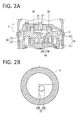
Figure 2] Figure 2A is a partially enlarged view ofFIG. 1 , andFIG. 2B is a cross-sectional view along the line IIb-IIb ofFIG. 2A . - [
Figure 3] Figure 3 is a view illustrating the function and effect of a discharge port of a fixed end plate of the embodiment, in whichFIG. 3A schematically shows a refrigerant discharge passage including the discharge port of the embodiment, andFIG. 3B schematically shows a conventional common refrigerant discharge passage. - [
Figure 4] Figure 4 is a view showing a modified example of the discharge port of the embodiment, in whichFIG. 4A shows an example in which a downstream port part is enlarged stepwise, andFIG. 4B shows an example in which the downstream port part is enlarged continuously. - In the following, the present invention will be described in detail on the basis of the embodiment shown in the accompanying drawings.
- As shown in
FIG. 1 , a scroll compressor 1 of this embodiment includes, inside ahousing 10, anelectric motor 12 and ascroll compression mechanism 2 driven by theelectric motor 12. This scroll compressor 1 compresses a refrigerant such as R410C or R407C and supplies it to a refrigerant circuit of an air conditioner or a refrigerator, for example. - The
housing 10 includes a cylindrical closed-end housingmain body 101 with an open upper end and ahousing top 102 covering the opening at the upper end of the housingmain body 101. - On the side surface of the housing
main body 101, a suction pipe 13 which introduces a refrigerant from an accumulator (not shown) into the housingmain body 101 is provided. - On the
housing top 102, a discharge pipe 14 which discharges a refrigerant compressed by thescroll compression mechanism 2 is provided. The inside of thehousing 10 is partitioned by adischarge cover 25 into a low-pressure chamber 10A and a high-pressure chamber 10B. - The
electric motor 12 includes astator 15 and a rotor 16. - The
stator 15 is provided with a winding which generates a magnetic field as power is supplied to it through a power source unit (not shown) mounted on the side surface of the housingmain body 101. The rotor 16 includes a permanent magnet and a yoke as main components, and further has amain shaft 17 integrally connected at the center. - An upper bearing 18 and a
lower bearing 19 which rotatably support themain shaft 17 are provided on both end sides of themain shaft 17 across theelectric motor 12. - In a
housing space 190 formed in the upper bearing 18, aneccentric pin 17A provided at the upper end of themain shaft 17 protrudes and is housed. - The
scroll compression mechanism 2 includes a fixedscroll 20 and aturning scroll 30 which makes a revolving turning motion relative to the fixedscroll 20. - The fixed
scroll 20 includes afixed end plate 21 and aspiral wrap 22 rising from one surface of thefixed end plate 21. The fixedscroll 20 also includes adischarge port 23 in thefixed end plate 21. Thedischarge port 23 passes through thefixed end plate 21 from one surface to the other surface, and has one end (the lower side in the drawing) open toward a compression chamber PR formed between the fixedscroll 20 and the turningscroll 30 and the other end (the upper side in the drawing) open toward adischarge port 27 of thedischarge cover 25 covering the upper side of the fixedscroll 20. - In this embodiment, the
discharge port 23 is composed of anupstream port part 23A located on the upstream side with reference to a flow direction F of the refrigerant (FIG. 2A ) and adownstream port part 23B located on the downstream side from theupstream port part 23A. Theupstream port part 23A continues to the compression chamber PR, while thedownstream port part 23B continues to theupstream port part 23A. As shown inFIG. 2B , theupstream port part 23A has a circular opening, and the opening area is denoted by A1. Thedownstream port part 23B has a fan-shaped opening, and the opening area is denoted by A2. In this embodiment, the opening area A2 of thedownstream port part 23B is larger than the opening area A1 of theupstream port part 23A. Moreover, due to this difference in opening area, a node of a vibration mode is generated in the border portion between theupstream port part 23A and thedownstream port part 23B. The function and effect of thedischarge port 23 thus being composed of theupstream port part 23A and thedownstream port part 23B will be described later. - The turning
scroll 30 includes a disc-shaped turningend plate 31 and aspiral wrap 32 rising from one surface of the turningend plate 31. - On the back surface of the turning
end plate 31 of the turningscroll 30, aboss 34 is provided and adrive bush 36 is installed in theboss 34 through the bearing. Theeccentric pin 17A is fitted inside thedrive bush 36. Thus, as the turningscroll 30 is connected eccentrically to the axis of themain shaft 17, when themain shaft 17 rotates, the turningscroll 30 turns (revolves) with a turning radius being the eccentric distance from the axis of themain shaft 17. - An Oldham ring (not shown) which restricts rotation is provided between the turning
scroll 30 and themain shaft 17 so that the turningscroll 30 revolves without rotating. - The wraps 22, 32, which are eccentric to each other by a predetermined amount and meshed 180 degrees out of phase, come into contact with each other at a plurality of positions according to the rotation angle of the turning
scroll 30. Then, the compression chamber PR is formed in point symmetry relative to a central part (most inner peripheral part) of the spiral of thewraps scroll 30 turns. The refrigerant is compressed maximally in the central part of the spiral. The compression chamber PR ofFIG. 1 is shown in this part. - In this
scroll compression mechanism 2, the volume of the compression chamber PR formed between bothscrolls scroll 20 and the turningscroll 30, the wrap height is lower on the inner peripheral side than on the outer peripheral side, and the end plate of the mating scroll opposite to this stepped wrap protrudes further toward the inner surface side of the end plate on the inner peripheral side than on the outer peripheral side. - To start the scroll compressor 1 thus configured, the
electric motor 12 is excited and a refrigerant is introduced through the suction pipe 13 into thehousing 10. - Upon excitation of the
electric motor 12, themain shaft 17 rotates and accordingly the turningscroll 30 makes a revolving turning motion relative to the fixedscroll 20. Then, the refrigerant is compressed in the compression chamber PR between the turningscroll 30 and the fixedscroll 20, and the refrigerant introduced into the low-pressure chamber 10A inside thehousing 10 from the suction pipe 13 is suctioned to a space between the turningscroll 30 and the fixedscroll 20. Then, the refrigerant compressed inside the compression chamber PR passes sequentially through thedischarge port 23 of thefixed end plate 21 and thedischarge port 27 of thedischarge cover 25 to be discharged into the high-pressure chamber 10B, and is further discharged from the discharge pipe 14 to the outside. In this way, the refrigerant is continuously suctioned, compressed, and discharged. - In this embodiment, the
discharge port 23 of the fixedscroll 20 is composed of the above-describedupstream port part 23A anddownstream port part 23B, and the opening area A2 of thedownstream port part 23B is larger than the opening area A1 of theupstream port part 23A, and moreover, a node of a vibration mode is generated at the border between theupstream port part 23A and thedownstream port part 23B. The function and effect of these features will be described with reference also toFIG. 3 . - First, a
conventional discharge port 123 with a constant opening area shown inFIG. 3B will be described. It is assumed that this opening area is A1, which is the same as that of theupstream port part 23A of this embodiment. That is, thedischarge port 123 is equivalent of theupstream port part 23A of this embodiment extending to the terminal end on the downstream side. - In
FIG. 3B , the wavelength λ in the formula (1) below is specified by the total value of L1', L2', and L3' defined below. When theconventional discharge port 123 is employed, the vibration mode is continuous between a passage C1' and a passage C2', but in a passage C3', a node of a vibration mode is generated at the border with the passage C1 and the passage C2 on the upstream side. When boundary conditions are taken into account, the total length L' (L1'+L2') of the passage C1' and the passage C2' is λ=4L'. As described above, the acoustic velocity of a refrigerant mixture such as R410A or 407C in a refrigerant passage is about 160 to 180 m/s, and when the fixed end plate thickness (L2') is assumed to be 10 to 20 mm and the scroll height (L1') is assumed to be 10 to 20 mm, the acoustic eigenvalue (f) of 1 to 2 kHz is obtained (where c=160 m/s). However, this can result in resonating with the structure.
where c: acoustic velocity (mm/s), f: frequency (kHz), and λ: wavelength (4L)
where L1': the length of the refrigerant passage C1' in the compression chamber PR, L2': the length of the refrigerant passage C2' in thefixed end plate 21, and L3': the length of the refrigerant passage C3' on the downstream side from the fixedend plate 21 - Therefore, as shown in
FIG. 3A of this embodiment, the opening of thedischarge port 23 is significantly expanded from the middle such that a node of a vibration mode is generated between the refrigerant passage (C1, C2) up to theupstream port part 23A and the refrigerant passage (C3) on the downstream side from thedownstream port part 23B. Then, since the length L corresponding to the conventional length L' is reduced, the acoustic eigenvalue (f) can be increased, so that resonance with the structure can be avoided. For example, when thedownstream port part 23B is formed from a position of a quarter of the thickness of thefixed end plate 21, the acoustic eigenvalue (f) is 1.6 to 3.2 kHz. - One can easily imagine that the length L can be reduced by reducing the thickness of the
fixed end plate 21. However, in order to secure the required strength of the fixedscroll 20, the thickness of thefixed end plate 21 cannot always be reduced. In particular, for highspeed rotation as well as weight reduction required of the scroll compressor 1, thefixed end plate 21 of the fixedscroll 20 as is already made thin within the allowable range, so that a further reduction in thickness is difficult. Therefore, the configuration of thedischarge port 23 of this embodiment is potent means for avoiding resonance with the structure without reducing the thickness of thefixed end plate 21. - Moreover, enlarging the opening area of the
downstream port part 23B as in thedischarge port 23 can reduce the pressure loss of a refrigerant in this portion, which can also contribute to performance improvement of the scroll compressor 1. - In this embodiment, the opening area A2 of the
downstream port part 23B is set such that a node of a vibration mode is generated in connection with the opening area A1 of theupstream port part 23A. The length L2 of theupstream port 23A is set, with vibration of the surrounding structure taken into account, such that the acoustic eigenvalue (f) at which resonance with the structure can be avoided is obtained. Both values can be obtained by performing a vibration test through simulation. - In the above-described embodiment, the example of the
downstream port part 23B of which the opening area is constant in the flow direction of the refrigerant has been shown. However, the present invention is not limited to this example. For example, as long as the effects of the present invention can be obtained, thedownstream port part 23B may be enlarged stepwise as shown inFIG. 4A , or thedownstream port part 23B may be enlarged continuously as shown inFIG. 4B . Although not shown, theupstream port part 23A may also be varied in opening area stepwise or continuously. - While the
downstream port part 23B has a fan-shaped opening, the present invention is not limited to this example, and thedownstream port part 23B may have another opening shape, for example, a circular shape. - Moreover, while the present invention has been described on the basis of the components in the range of 1 k to 2 kHz of discharge pulsation being generated as noise, this is merely an example, and it is needless to say that the present invention can be employed in order to reduce noise components outside of this range.
- Furthermore, the opening shape of the
downstream port part 23B is arbitrary and not limited to the fan shape. - Otherwise, the configurations presented in the above-described embodiments can be sorted out or changed to other configurations within the scope of the present invention.
-
- 1
- Scroll compressor
- 2
- Scroll compression mechanism
- 10
- Housing
- 10A
- Low-pressure chamber
- 10B
- High-pressure chamber
- 12
- Electric motor
- 13
- Suction pipe
- 14
- Discharge pipe
- 15
- Stator
- 16
- Rotor
- 17
- Main shaft
- 17A
- Eccentric pin
- 18
- Upper bearing
- 19
- Lower bearing
- 20
- Fixed scroll
- 22, 32
- Wrap
- 23
- Discharge port
- 23A
- Upstream port part
- 23B
- Downstream port part
- 25
- Discharge cover
- 27
- Discharge port
- 30
- Turning scroll
- 34
- Boss
- 36
- Drive bush
- 101
- Housing main body
- 102
- Housing top
- 21
- Fixed end plate
- 31
- Turning end plate
Claims (2)
- A scroll compressor comprising:a turning scroll which is rotatably coupled with an eccentric shaft part of a main shaft; anda fixed scroll which is opposed to the turning scroll to thereby form a compression chamber for compressing a refrigerant and has an end plate in which a discharge port for discharging the compressed refrigerant toward a high-pressure chamber is formed, whereinthe discharge port is composed of an upstream port part which continues to the compression chamber and has an opening area A1 and a downstream port part which continues to the upstream port part and has an opening area A2 larger than the opening area A1 of the upstream port part, anda node of a vibration mode is generated at the border between the upstream port part and the downstream port part.
- The scroll compressor according to claim 1, wherein the opening area A2 of the downstream port part is uniform, or enlarged stepwise or continuously, in a flow direction of the refrigerant.
Applications Claiming Priority (2)
| Application Number | Priority Date | Filing Date | Title |
|---|---|---|---|
| JP2012257840A JP5951456B2 (en) | 2012-11-26 | 2012-11-26 | Scroll compressor |
| PCT/JP2013/005482 WO2014080553A1 (en) | 2012-11-26 | 2013-09-17 | Scroll compressor |
Publications (2)
| Publication Number | Publication Date |
|---|---|
| EP2918841A1 true EP2918841A1 (en) | 2015-09-16 |
| EP2918841A4 EP2918841A4 (en) | 2015-12-16 |
Family
ID=50775751
Family Applications (1)
| Application Number | Title | Priority Date | Filing Date |
|---|---|---|---|
| EP13856394.5A Withdrawn EP2918841A4 (en) | 2012-11-26 | 2013-09-17 | Scroll compressor |
Country Status (4)
| Country | Link |
|---|---|
| EP (1) | EP2918841A4 (en) |
| JP (1) | JP5951456B2 (en) |
| CN (1) | CN104755762B (en) |
| WO (1) | WO2014080553A1 (en) |
Cited By (1)
| Publication number | Priority date | Publication date | Assignee | Title |
|---|---|---|---|---|
| US12071950B2 (en) | 2019-10-11 | 2024-08-27 | Mitsubishi Heavy Industries Thermal Systems, Ltd. | Electric compressor |
Families Citing this family (1)
| Publication number | Priority date | Publication date | Assignee | Title |
|---|---|---|---|---|
| JP3454069B2 (en) | 1997-02-11 | 2003-10-06 | 三菱ふそうトラック・バス株式会社 | Glide slide door seal structure |
Family Cites Families (8)
| Publication number | Priority date | Publication date | Assignee | Title |
|---|---|---|---|---|
| US5342183A (en) | 1992-07-13 | 1994-08-30 | Copeland Corporation | Scroll compressor with discharge diffuser |
| JPH07269485A (en) * | 1994-03-31 | 1995-10-17 | Mitsubishi Heavy Ind Ltd | Compressor |
| JPH08319963A (en) * | 1995-03-22 | 1996-12-03 | Mitsubishi Electric Corp | Scroll compressor |
| JP2009167983A (en) * | 2008-01-18 | 2009-07-30 | Daikin Ind Ltd | Scroll compressor |
| AU2009239310A1 (en) * | 2008-04-22 | 2009-10-29 | Panasonic Corporation | Scroll compressor |
| JP2010065560A (en) * | 2008-09-09 | 2010-03-25 | Daikin Ind Ltd | Scroll compressor |
| JP4775494B2 (en) * | 2010-02-15 | 2011-09-21 | ダイキン工業株式会社 | Scroll compressor |
| JP5758112B2 (en) * | 2010-12-07 | 2015-08-05 | 三菱重工業株式会社 | Scroll compressor |
-
2012
- 2012-11-26 JP JP2012257840A patent/JP5951456B2/en active Active
-
2013
- 2013-09-17 EP EP13856394.5A patent/EP2918841A4/en not_active Withdrawn
- 2013-09-17 WO PCT/JP2013/005482 patent/WO2014080553A1/en not_active Ceased
- 2013-09-17 CN CN201380056491.5A patent/CN104755762B/en active Active
Cited By (1)
| Publication number | Priority date | Publication date | Assignee | Title |
|---|---|---|---|---|
| US12071950B2 (en) | 2019-10-11 | 2024-08-27 | Mitsubishi Heavy Industries Thermal Systems, Ltd. | Electric compressor |
Also Published As
| Publication number | Publication date |
|---|---|
| CN104755762B (en) | 2016-10-26 |
| CN104755762A (en) | 2015-07-01 |
| JP2014105606A (en) | 2014-06-09 |
| EP2918841A4 (en) | 2015-12-16 |
| WO2014080553A1 (en) | 2014-05-30 |
| JP5951456B2 (en) | 2016-07-13 |
Similar Documents
| Publication | Publication Date | Title |
|---|---|---|
| CN108626125B (en) | Rotary compressor | |
| EP3447296A1 (en) | Compressor | |
| EP2634432A1 (en) | Screw compressor | |
| EP3015710B1 (en) | Compressor | |
| CN102439311B (en) | Linearkompressor | |
| EP3015709B1 (en) | Scroll-type compressor | |
| JP2011047383A (en) | Scroll compressor | |
| JP6037563B2 (en) | Multi-cylinder rotary compressor and refrigeration cycle apparatus | |
| EP2894341B1 (en) | Compressor | |
| JP5709503B2 (en) | Scroll compressor and refrigeration cycle apparatus equipped with the scroll compressor | |
| JP5758112B2 (en) | Scroll compressor | |
| JP3555611B2 (en) | Hermetic compressor | |
| JP5951456B2 (en) | Scroll compressor | |
| JP5247194B2 (en) | Scroll compressor | |
| EP3572670A1 (en) | Scroll compressor | |
| KR20180104871A (en) | Rotary compressor | |
| JP2012117392A (en) | Scroll compressor | |
| JP2007154762A (en) | Scroll compressor | |
| JP2009167983A (en) | Scroll compressor | |
| WO2022172356A1 (en) | Scroll compressor | |
| CN112585357A (en) | Hermetic compressor | |
| JP5179955B2 (en) | Positive displacement compressor | |
| JP2014118862A (en) | Rotary compressor | |
| KR101491142B1 (en) | Noise reduction device of scroll compressor | |
| JP5916419B2 (en) | Scroll compressor |
Legal Events
| Date | Code | Title | Description |
|---|---|---|---|
| PUAI | Public reference made under article 153(3) epc to a published international application that has entered the european phase |
Free format text: ORIGINAL CODE: 0009012 |
|
| 17P | Request for examination filed |
Effective date: 20150430 |
|
| AK | Designated contracting states |
Kind code of ref document: A1 Designated state(s): AL AT BE BG CH CY CZ DE DK EE ES FI FR GB GR HR HU IE IS IT LI LT LU LV MC MK MT NL NO PL PT RO RS SE SI SK SM TR |
|
| AX | Request for extension of the european patent |
Extension state: BA ME |
|
| RA4 | Supplementary search report drawn up and despatched (corrected) |
Effective date: 20151117 |
|
| RIC1 | Information provided on ipc code assigned before grant |
Ipc: F04C 18/02 20060101AFI20151111BHEP Ipc: F04C 23/00 20060101ALI20151111BHEP Ipc: F04C 29/12 20060101ALI20151111BHEP |
|
| DAX | Request for extension of the european patent (deleted) | ||
| RAP1 | Party data changed (applicant data changed or rights of an application transferred) |
Owner name: MITSUBISHI HEAVY INDUSTRIES THERMAL SYSTEMS, LTD. |
|
| 17Q | First examination report despatched |
Effective date: 20190806 |
|
| STAA | Information on the status of an ep patent application or granted ep patent |
Free format text: STATUS: THE APPLICATION HAS BEEN WITHDRAWN |
|
| 18W | Application withdrawn |
Effective date: 20190830 |