EP2918689A1 - Laser processing device and laser radiation method - Google Patents
Laser processing device and laser radiation method Download PDFInfo
- Publication number
- EP2918689A1 EP2918689A1 EP13852814.6A EP13852814A EP2918689A1 EP 2918689 A1 EP2918689 A1 EP 2918689A1 EP 13852814 A EP13852814 A EP 13852814A EP 2918689 A1 EP2918689 A1 EP 2918689A1
- Authority
- EP
- European Patent Office
- Prior art keywords
- intensity
- steel sheet
- laser
- intensity distribution
- centroid
- Prior art date
- Legal status (The legal status is an assumption and is not a legal conclusion. Google has not performed a legal analysis and makes no representation as to the accuracy of the status listed.)
- Granted
Links
Images



Classifications
-
- H—ELECTRICITY
- H01—ELECTRIC ELEMENTS
- H01F—MAGNETS; INDUCTANCES; TRANSFORMERS; SELECTION OF MATERIALS FOR THEIR MAGNETIC PROPERTIES
- H01F1/00—Magnets or magnetic bodies characterised by the magnetic materials therefor; Selection of materials for their magnetic properties
- H01F1/01—Magnets or magnetic bodies characterised by the magnetic materials therefor; Selection of materials for their magnetic properties of inorganic materials
- H01F1/03—Magnets or magnetic bodies characterised by the magnetic materials therefor; Selection of materials for their magnetic properties of inorganic materials characterised by their coercivity
- H01F1/12—Magnets or magnetic bodies characterised by the magnetic materials therefor; Selection of materials for their magnetic properties of inorganic materials characterised by their coercivity of soft-magnetic materials
- H01F1/14—Magnets or magnetic bodies characterised by the magnetic materials therefor; Selection of materials for their magnetic properties of inorganic materials characterised by their coercivity of soft-magnetic materials metals or alloys
- H01F1/147—Alloys characterised by their composition
- H01F1/14766—Fe-Si based alloys
- H01F1/14775—Fe-Si based alloys in the form of sheets
-
- B—PERFORMING OPERATIONS; TRANSPORTING
- B23—MACHINE TOOLS; METAL-WORKING NOT OTHERWISE PROVIDED FOR
- B23K—SOLDERING OR UNSOLDERING; WELDING; CLADDING OR PLATING BY SOLDERING OR WELDING; CUTTING BY APPLYING HEAT LOCALLY, e.g. FLAME CUTTING; WORKING BY LASER BEAM
- B23K26/00—Working by laser beam, e.g. welding, cutting or boring
- B23K26/352—Working by laser beam, e.g. welding, cutting or boring for surface treatment
-
- B—PERFORMING OPERATIONS; TRANSPORTING
- B23—MACHINE TOOLS; METAL-WORKING NOT OTHERWISE PROVIDED FOR
- B23K—SOLDERING OR UNSOLDERING; WELDING; CLADDING OR PLATING BY SOLDERING OR WELDING; CUTTING BY APPLYING HEAT LOCALLY, e.g. FLAME CUTTING; WORKING BY LASER BEAM
- B23K26/00—Working by laser beam, e.g. welding, cutting or boring
- B23K26/02—Positioning or observing the workpiece, e.g. with respect to the point of impact; Aligning, aiming or focusing the laser beam
- B23K26/06—Shaping the laser beam, e.g. by masks or multi-focusing
- B23K26/062—Shaping the laser beam, e.g. by masks or multi-focusing by direct control of the laser beam
-
- C—CHEMISTRY; METALLURGY
- C21—METALLURGY OF IRON
- C21D—MODIFYING THE PHYSICAL STRUCTURE OF FERROUS METALS; GENERAL DEVICES FOR HEAT TREATMENT OF FERROUS OR NON-FERROUS METALS OR ALLOYS; MAKING METAL MALLEABLE, e.g. BY DECARBURISATION OR TEMPERING
- C21D1/00—General methods or devices for heat treatment, e.g. annealing, hardening, quenching or tempering
- C21D1/06—Surface hardening
- C21D1/09—Surface hardening by direct application of electrical or wave energy; by particle radiation
-
- C—CHEMISTRY; METALLURGY
- C21—METALLURGY OF IRON
- C21D—MODIFYING THE PHYSICAL STRUCTURE OF FERROUS METALS; GENERAL DEVICES FOR HEAT TREATMENT OF FERROUS OR NON-FERROUS METALS OR ALLOYS; MAKING METAL MALLEABLE, e.g. BY DECARBURISATION OR TEMPERING
- C21D1/00—General methods or devices for heat treatment, e.g. annealing, hardening, quenching or tempering
- C21D1/34—Methods of heating
-
- C—CHEMISTRY; METALLURGY
- C21—METALLURGY OF IRON
- C21D—MODIFYING THE PHYSICAL STRUCTURE OF FERROUS METALS; GENERAL DEVICES FOR HEAT TREATMENT OF FERROUS OR NON-FERROUS METALS OR ALLOYS; MAKING METAL MALLEABLE, e.g. BY DECARBURISATION OR TEMPERING
- C21D6/00—Heat treatment of ferrous alloys
- C21D6/008—Heat treatment of ferrous alloys containing Si
-
- C—CHEMISTRY; METALLURGY
- C21—METALLURGY OF IRON
- C21D—MODIFYING THE PHYSICAL STRUCTURE OF FERROUS METALS; GENERAL DEVICES FOR HEAT TREATMENT OF FERROUS OR NON-FERROUS METALS OR ALLOYS; MAKING METAL MALLEABLE, e.g. BY DECARBURISATION OR TEMPERING
- C21D8/00—Modifying the physical properties of ferrous metals or ferrous alloys by deformation combined with, or followed by, heat treatment
- C21D8/12—Modifying the physical properties of ferrous metals or ferrous alloys by deformation combined with, or followed by, heat treatment during manufacturing of articles with special electromagnetic properties
- C21D8/1294—Modifying the physical properties of ferrous metals or ferrous alloys by deformation combined with, or followed by, heat treatment during manufacturing of articles with special electromagnetic properties involving a localised treatment
-
- C—CHEMISTRY; METALLURGY
- C21—METALLURGY OF IRON
- C21D—MODIFYING THE PHYSICAL STRUCTURE OF FERROUS METALS; GENERAL DEVICES FOR HEAT TREATMENT OF FERROUS OR NON-FERROUS METALS OR ALLOYS; MAKING METAL MALLEABLE, e.g. BY DECARBURISATION OR TEMPERING
- C21D9/00—Heat treatment, e.g. annealing, hardening, quenching or tempering, adapted for particular articles; Furnaces therefor
- C21D9/46—Heat treatment, e.g. annealing, hardening, quenching or tempering, adapted for particular articles; Furnaces therefor for sheet metals
-
- C—CHEMISTRY; METALLURGY
- C22—METALLURGY; FERROUS OR NON-FERROUS ALLOYS; TREATMENT OF ALLOYS OR NON-FERROUS METALS
- C22C—ALLOYS
- C22C38/00—Ferrous alloys, e.g. steel alloys
- C22C38/001—Ferrous alloys, e.g. steel alloys containing N
-
- C—CHEMISTRY; METALLURGY
- C22—METALLURGY; FERROUS OR NON-FERROUS ALLOYS; TREATMENT OF ALLOYS OR NON-FERROUS METALS
- C22C—ALLOYS
- C22C38/00—Ferrous alloys, e.g. steel alloys
- C22C38/02—Ferrous alloys, e.g. steel alloys containing silicon
-
- C—CHEMISTRY; METALLURGY
- C22—METALLURGY; FERROUS OR NON-FERROUS ALLOYS; TREATMENT OF ALLOYS OR NON-FERROUS METALS
- C22C—ALLOYS
- C22C38/00—Ferrous alloys, e.g. steel alloys
- C22C38/04—Ferrous alloys, e.g. steel alloys containing manganese
-
- C—CHEMISTRY; METALLURGY
- C22—METALLURGY; FERROUS OR NON-FERROUS ALLOYS; TREATMENT OF ALLOYS OR NON-FERROUS METALS
- C22C—ALLOYS
- C22C38/00—Ferrous alloys, e.g. steel alloys
- C22C38/06—Ferrous alloys, e.g. steel alloys containing aluminium
-
- H—ELECTRICITY
- H01—ELECTRIC ELEMENTS
- H01F—MAGNETS; INDUCTANCES; TRANSFORMERS; SELECTION OF MATERIALS FOR THEIR MAGNETIC PROPERTIES
- H01F1/00—Magnets or magnetic bodies characterised by the magnetic materials therefor; Selection of materials for their magnetic properties
- H01F1/01—Magnets or magnetic bodies characterised by the magnetic materials therefor; Selection of materials for their magnetic properties of inorganic materials
- H01F1/03—Magnets or magnetic bodies characterised by the magnetic materials therefor; Selection of materials for their magnetic properties of inorganic materials characterised by their coercivity
- H01F1/12—Magnets or magnetic bodies characterised by the magnetic materials therefor; Selection of materials for their magnetic properties of inorganic materials characterised by their coercivity of soft-magnetic materials
- H01F1/14—Magnets or magnetic bodies characterised by the magnetic materials therefor; Selection of materials for their magnetic properties of inorganic materials characterised by their coercivity of soft-magnetic materials metals or alloys
- H01F1/16—Magnets or magnetic bodies characterised by the magnetic materials therefor; Selection of materials for their magnetic properties of inorganic materials characterised by their coercivity of soft-magnetic materials metals or alloys in the form of sheets
-
- H—ELECTRICITY
- H01—ELECTRIC ELEMENTS
- H01F—MAGNETS; INDUCTANCES; TRANSFORMERS; SELECTION OF MATERIALS FOR THEIR MAGNETIC PROPERTIES
- H01F41/00—Apparatus or processes specially adapted for manufacturing or assembling magnets, inductances or transformers; Apparatus or processes specially adapted for manufacturing materials characterised by their magnetic properties
- H01F41/02—Apparatus or processes specially adapted for manufacturing or assembling magnets, inductances or transformers; Apparatus or processes specially adapted for manufacturing materials characterised by their magnetic properties for manufacturing cores, coils, or magnets
-
- C—CHEMISTRY; METALLURGY
- C21—METALLURGY OF IRON
- C21D—MODIFYING THE PHYSICAL STRUCTURE OF FERROUS METALS; GENERAL DEVICES FOR HEAT TREATMENT OF FERROUS OR NON-FERROUS METALS OR ALLOYS; MAKING METAL MALLEABLE, e.g. BY DECARBURISATION OR TEMPERING
- C21D8/00—Modifying the physical properties of ferrous metals or ferrous alloys by deformation combined with, or followed by, heat treatment
- C21D8/02—Modifying the physical properties of ferrous metals or ferrous alloys by deformation combined with, or followed by, heat treatment during manufacturing of plates or strips
-
- C—CHEMISTRY; METALLURGY
- C21—METALLURGY OF IRON
- C21D—MODIFYING THE PHYSICAL STRUCTURE OF FERROUS METALS; GENERAL DEVICES FOR HEAT TREATMENT OF FERROUS OR NON-FERROUS METALS OR ALLOYS; MAKING METAL MALLEABLE, e.g. BY DECARBURISATION OR TEMPERING
- C21D8/00—Modifying the physical properties of ferrous metals or ferrous alloys by deformation combined with, or followed by, heat treatment
- C21D8/10—Modifying the physical properties of ferrous metals or ferrous alloys by deformation combined with, or followed by, heat treatment during manufacturing of tubular bodies
-
- C—CHEMISTRY; METALLURGY
- C21—METALLURGY OF IRON
- C21D—MODIFYING THE PHYSICAL STRUCTURE OF FERROUS METALS; GENERAL DEVICES FOR HEAT TREATMENT OF FERROUS OR NON-FERROUS METALS OR ALLOYS; MAKING METAL MALLEABLE, e.g. BY DECARBURISATION OR TEMPERING
- C21D8/00—Modifying the physical properties of ferrous metals or ferrous alloys by deformation combined with, or followed by, heat treatment
- C21D8/12—Modifying the physical properties of ferrous metals or ferrous alloys by deformation combined with, or followed by, heat treatment during manufacturing of articles with special electromagnetic properties
Definitions
- the present invention relates to a laser processing apparatus and a laser irradiation method in which magnetic domains are controlled by applying a laser beam to a grain-oriented electrical steel sheet used for transformer cores and the like.
- a grain-oriented electrical steel sheet has a characteristic of easily allowing the penetration of the magnetic lines of force with respect to the rolling direction during the manufacture of a steel sheet (having an easy magnetization direction along the rolling direction) (henceforth, also referred to as a one-oriented electrical steel sheet), and is used as a material constituting an iron core of electric devices such as a transformer and a rotator.
- a steel sheet having an easy magnetization direction along the rolling direction
- the grain-oriented electrical steel sheet used for iron cores there has been a demand to reduce the energy loss (core loss) during magnetization.
- core loss energy loss
- the core loss is classified into an eddy-current loss and a hysteresis loss. Furthermore, the eddy-current loss can be classified into a classical eddy-current loss and an anomalous eddy-current loss.
- a thin grain-oriented electrical steel sheet having an insulation film on the sheet surface As the grain-oriented electrical steel sheet having an insulation film formed thereon, for example, as described in Patent Document 1, a steel sheet having a double-layered structure in which the surface of a base steel sheet (metal section) is coated with a glass film and the glass film is coated with an insulation film has been proposed and put into practical use.
- the scanning and irradiation of a laser beam imparts a temperature history having a strong temperature gradient with respect to the sheet thickness direction to the outermost layer region of the steel sheet, the temperature history generates surface strain, the surface strain causes closure domains, the closure domains reduce the 180° domain wall spacing, and particularly, the anomalous eddy-current loss is reduced.
- Patent Document 3 discloses a method in which strong strain is formed in a narrow region using a TEM 00 mode laser beam having an excellent focusability, and narrow closure domains having a sufficient intensity are obtained.
- the magnetic domains are controlled by forming an insulation film on a glass film, and radiating a laser beam above the insulation film.
- the irradiation of a laser beam increases the temperature, and the increase in the temperature generates flaws in the insulation film and the glass film.
- the flaws refer to film damage such as the exfoliation, uplift, property change, and color change of the insulation film and the glass film.
- the metal section below the film becomes exposed to the outside, and there is a concern that rust may be generated. Therefore, in a case in which flaws are generated in the glass film, it is necessary to apply the insulation film again. In such a case, the addition of a step increases the manufacturing costs.
- Patent Document 4 discloses a method in which the beam is provided with an elliptic shape that is long in the scanning direction of the laser beam.
- An object of the present invention is to provide a laser processing apparatus and a laser irradiation method in which it is possible to suppress the generation of flaws in a glass film while reducing the core loss of a grain-oriented electrical steel sheet.
- a grain-oriented electrical steel sheet refers to an electrical steel sheet in which the easy magnetization axes (in a ⁇ 100> direction of a body-centered cubic crystal) of crystal grains in the steel sheet substantially align along a rolling direction in a manufacturing step.
- the grain-oriented electrical steel sheet has a structure in which magnetic domains magnetized in the rolling direction are arrayed in multiple rows with a magnetic wall interposed therebetween.
- the grain-oriented electrical steel sheet is easily magnetized in the rolling direction, and is thus suitable for a core material of a transformer in which the directions of the magnetic lines of force are almost constant.
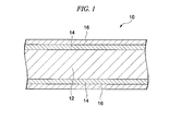
- FIG 1 is a cross-sectional view of a grain-oriented electrical steel sheet 10 according to the present embodiment.
- the grain-oriented electrical steel sheet 10 includes a base steel sheet (metal section) 12, glass films 14 formed on both surfaces of the base steel sheet 12, and insulation films 16 formed on the glass films 14.
- Transformers are roughly classified into laminated core transformers and toroidal transformers.
- a steel sheet is changed toroidally in shape by a bending deformation so as to have a transformer shape, and then is annealed to remove strain introduced due to the mechanical deformation (stress-relief annealing step).
- the grain-oriented electrical steel sheet 10 according to the present embodiment is particularly suitable as a material for the laminated core transformers.
- the base steel sheet 12 is constituted of an iron alloy containing Si.
- An example of the chemical composition of the base steel sheet 12 is Si: 2.5 mass% to 4.0 mass%, C: 0.02 mass% to 0.10 mass%, Mn: 0.05 mass% to 0.20 mass%, acid-soluble Al: 0.020 mass% to 0.040 mass%, N: 0.002 mass% to 0.012 mass%, S: 0.001 mass% to 0.010 mass%, and P: 0.01 mass% to 0.04 mass% with the balance of Fe and impurities.
- the thickness of the base steel sheet 12 is, for example, within a range of 0.2 mm to 0.3 mm.
- the glass film 14 is constituted of a multiple oxide, for example, forsterite (Mg 2 SiO 4 ), spinel (MgAl 2 O 4 ), or cordierite (Mg 2 Al 4 Si 5 O 16 ).
- the thickness of the glass film 14 is, for example, 1 ⁇ m.
- the insulation film 16 is formed by, for example, baking a coating solution mainly including colloidal silica and a phosphate (magnesium phosphate, aluminum phosphate, or the like) or a coating solution that is a mixture of an alumina sol and boric acid.
- the thickness of the insulation film 16 is, for example, within a range of 2 ⁇ m to 3 ⁇ m.
- a laser beam is focused, is emitted above the insulation film 16, and the grain-oriented electrical steel sheet is scanned substantially in a width direction (a direction substantially orthogonal to a rolling direction) of the grain-oriented electrical steel sheet being transported in the rolling direction (transportation direction) with the laser beam.
- Temperature gradients in the sheet thickness direction and the sheet width direction which are caused by the irradiation of the laser beam, impart residual strain in linear regions almost orthogonal to the rolling direction.
- the linear regions imparted with the residual strain are generated in predetermined periods in the rolling direction, and in regions which are interposed between two linear regions and are magnetized in the rolling direction, the magnetic domain widths in a direction substantially orthogonal to the rolling direction are reduced.
- the above-described grain-oriented electrical steel sheet will be referred to as the grain-oriented electrical steel sheet according to the present embodiment.
- FIG. 2 is a flowchart showing an example of a step for manufacturing the grain-oriented electrical steel sheet 10 according to the present embodiment.
- the step for manufacturing the grain-oriented electrical steel sheet 10, as shown in FIG. 2 includes a casting step S2, a hot rolling step S4, an annealing step S6, a cold rolling step S8, a decarburization annealing step S10, an annealing separator coating step S 12, a final annealing step S14, an insulation film formation step S16, and a laser irradiation step S18.
- molten steel adjusted to have a predetermined composition is supplied to a continuous casting machine, and a slab is continuously formed.
- the slab is heated to a predetermined temperature (for example, 1150°C to 1400°C), and is hot-rolled.
- a hot-rolled sheet having a predetermined thickness for example, 1.8 mm to 3.5 mm
- a thermal treatment (annealing) is carried out on the hot-rolled sheet under conditions of, for example, a heating temperature within a range of 750°C to 1200°C and a heating time within a range of 30 seconds to 10 minutes.
- the cold rolling step S8 the surface of the hot-rolled sheet is pickled, and then cold rolling is carried out. As a result, a cold-rolled sheet having a predetermined thickness (for example, 0.15 mm to 0.35 mm) is obtained.
- a thermal treatment (decarburization annealing) is carried out on the cold-rolled sheet under conditions of, for example, a heating temperature within a range of 700°C to 900°C and a heating time within a range of 1 minute to 3 minutes, thereby obtaining the base steel sheet 12.
- a heating temperature within a range of 700°C to 900°C
- a heating time within a range of 1 minute to 3 minutes, thereby obtaining the base steel sheet 12.
- an oxide layer mainly including silica (SiO 2 ) forms on the surface of the base steel sheet 12.
- an annealing separator coating step S12 an annealing separator mainly including magnesia (MgO) is applied onto the oxide layer on the surface of the base steel sheet 12.
- MgO magnesia
- the base steel sheet 12 onto which the annealing separator has been applied is coiled in a coil shape, is put into a batch-type furnace, and a thermal treatment (final annealing) is carried out.
- the thermal treatment conditions are, for example, a heating temperature within a range of 1100°C to 1300°C and a heating time within a range of 20 hours to 24 hours.
- Goss grains which have easy magnetization axes in the transportation direction (rolling direction) of the base steel sheet 12 preferentially grow.
- a grain-oriented electrical steel sheet having a high crystal orientation (crystal alignment) is obtained after the final annealing.
- the oxide layer and the annealing separator react to each other, and the glass film 14 made of forsterite (Mg 2 SiO 4 ) forms on the surface of the base steel sheet 12.
- the base steel sheet 12 which has been coiled in a coil shape is uncoiled, is stretched in a sheet shape, and is transported.
- an insulating material is applied onto the glass films 14 formed on both surfaces of the base steel sheet 12, and is baked, thereby forming the insulation films 16.
- the base steel sheet 12 on which the insulation films 16 are formed is coiled in a coil shape.
- the base steel sheet 12 which has been coiled in a coil shape is uncoiled, is stretched in a sheet shape, and is transported.
- a laser beam is focused and a single surface of the base steel sheet 12 is irradiated with the laser beam using a laser irradiation unit according to the present embodiment described below, and the grain-oriented electrical steel sheet is scanned substantially in a width direction (a direction substantially orthogonal to the rolling direction) of the grain-oriented electrical steel sheet being transported in the rolling direction (transportation direction) with the laser beam. Therefore, linear strain almost orthogonal to the rolling direction is formed on the surface of the base steel sheet 12 at predetermined intervals in the rolling direction.
- the focusing and scanning of the laser beam may be carried out only on the front or back surface of the base steel sheet 12, or may be carried out on both the front and back surfaces.
- the base steel sheet 12 on which the insulation films 16 are formed is coiled in a coil shape, and then is sent to the laser irradiation step S18, but it is also possible to carry out the laser irradiation immediately after the formation of the insulation films, and then coil the base steel sheet in a coil shape.
- the glass films 14 and the insulation films 16 are formed on the surfaces of the base steel sheet 12, and are irradiated with the laser beam, thereby manufacturing the grain-oriented electrical steel sheet 10 in which magnetic domains are controlled.
- FIGS. 3 and 4 a constitution of an example of the laser processing apparatus 100 (hereinafter, in some cases, referred to as the laser processing apparatus according to the present embodiment) that irradiates the grain-oriented electrical steel sheet 10 with a laser beam according to the present embodiment so as to impart the residual strain will be described.
- the laser processing apparatus 100 according to the present embodiment is used to irradiate the grain-oriented electrical steel sheet 10 with a laser beam in the laser irradiation step S18.
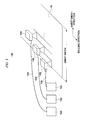
- FIG 3 is a schematic view showing a constitution of an example of the laser processing apparatus 100 according to the present embodiment.
- the laser processing apparatus 100 emits a laser beam above the insulation film 16 in the grain-oriented electrical steel sheet 10 being transported in the rolling direction at a certain speed, thereby imparting linear strain almost orthogonal to the rolling direction.
- the laser processing apparatus 100 includes a plurality of laser oscillators 102, a plurality of transmission fibers 104, and a plurality of laser irradiation units 106.
- FIG 3 three laser oscillators 102, three transmission fibers 104, and three laser irradiation units 106 are shown, and the respective constitutions are the same.
- FIG 4 is a schematic view shown a constitution of an example of the laser irradiation unit 106.
- the laser oscillator 102 emits, for example, a high-output laser beam.
- the transmission fiber 104 is an optical fiber that transmits a laser beam emitted from the laser oscillator 102 to the laser irradiation unit 106.
- a fiber laser or a disc laser is preferred.
- the fiber laser or the disc laser has a wavelength in a near-ultraviolet to near-infrared range (for example, a 1 ⁇ m band), and is thus capable of transmitting a laser beam using an optical fiber.
- a laser beam is transmitted using an optical fiber, a more compact laser processing apparatus 100 can be realized.
- the laser oscillator 102 may be a continuous wave laser or a pulse laser.
- the beam quality parameter product of the laser beam is preferably 10 (mm ⁇ mrad) or less.
- the spot radius of the laser beam and the depth of focus of the laser beam are dependent on the beam qualities.
- the beam qualities are generally quantified using a beam parameter product (BPP).
- FIG. 5 is a schematic view showing the beam parameter product (BPP).
- BPP beam parameter product
- the laser beam that has passed through a lens is focused to a beam diameter with a radius r, and then is enlarged again.
- the laser beam is focused at an angle ⁇ .
- the beam parameter product (BPP) is expressed by Equation (1) described below in units of mm ⁇ mrad.
- BPP r ⁇ ⁇
- DOF the depth of focus
- BPP is set to 10 (mm ⁇ mrad) or less, even in a case in which r is set to 0.06 mm to obtain a narrower closure domain width, it is possible to ensure a DOF of 0.7 mm or more.
- a DOF of 0.7 mm or more is ensured, even in a case in which the grain-oriented electrical steel sheet 10 vibrates in a direction perpendicular to the sheet surface, it is effective to appropriately reduce magnetic domain size.
- the lower limit value of BPP is ⁇ / ⁇ (mm ⁇ mrad) when the wavelength of the laser beam is ⁇ ( ⁇ m).
- the laser irradiation unit 106 focuses the laser beam transmitted from the laser oscillator 102 using the transmission fiber 104 on the grain-oriented electrical steel sheet 10 and scans the grain-oriented electrical steel sheet 10 with the focused laser beam.
- the width to be scanned with the laser beam by the laser irradiation unit 106 may be narrower than the sheet width of the grain-oriented electrical steel sheet 10.
- the laser irradiation units 106 are arrayed in multiple rows in the sheet width direction as shown in FIG. 3 , it is possible to scan the entire sheet width of the grain-oriented electrical steel sheet 10 with the laser beam.
- the laser irradiation unit 106 includes a laser head 122, a collimator lens 124, a metal mirror 126, a polygon mirror 128, and a paraboloid mirror 130.
- the laser head 122 emits the laser beam transmitted using the transmission fiber 104 at a predetermined divergence angle.
- the collimator lens 124 alters the laser beam emitted from the laser head 122 to a collimated beam.
- the metal mirror 126 is a mirror to reduce and adjust the beam diameter of the incident laser beam in the sheet width direction (refer to FIG. 3 ) of the grain-oriented electrical steel sheet 10.
- the metal mirror 126 it is possible to use, for example, a columnar mirror or a paraboloid mirror which has curvature in a single axis direction.
- the laser beam reflected on the metal mirror 126 is incident on the polygon mirror 128 rotating at a predetermined rotation speed.
- the polygon mirror 128 is a rotatable polyhedron, and moves the laser beam in the sheet width direction of the grain-oriented electrical steel sheet 10 by being rotated. While the laser beam is incident on one surface of the polyhedron of the polygon mirror 128, a linear region is scanned with the laser beam substantially in a sheet width direction on the grain-oriented electrical steel sheet 10 in accordance with the rotation of the surface. As a result, residual strain is imparted to the linear region. In accordance with the rotation of the polygon mirror 128, scanning is repeated with the laser beam, and simultaneously, the grain-oriented electrical steel sheet 10 is transported in the rolling direction. As a result, regions having linear residual strain are periodically formed on the grain-oriented electrical steel sheet 10 in the rolling direction. Meanwhile, the period of the linear regions in the rolling direction is adjusted using the transportation speed of the grain-oriented electrical steel sheet 10 and the rotation speed of the polygon mirror 128.
- the paraboloid mirror 130 is a mirror to reduce and adjust the beam diameter of the laser beam reflected on the polygon mirror 128 in the rolling direction.
- the laser beam reflected by the paraboloid mirror 130 is focused on the surface of the grain-oriented electrical steel sheet 10.
- FIG 6 is a view showing the spot shape of the laser beam on the grain-oriented electrical steel sheet 10.
- the spot shape of the laser beam is an elliptical shape as shown in FIG 6 , and has a long axis along the scanning direction of the laser beam LB (the long axis and the scanning direction of the laser beam LB are almost parallel to each other) and a short axis substantially orthogonal to the scanning direction (that is, almost 90°, and cases of being not strictly 90° are also included).
- the spot shape is set to an elliptical shape as described above, the heating time by the irradiation with the laser beam at one point on the steel sheet becomes long.
- the temperatures at deep positions inside the grain-oriented electrical steel sheet 10 can be increased, and the core loss can be effectively reduced.
- a spot shape of the laser beam an elliptical spot can be obtained by reducing the beam diameter in the scanning direction of the laser beam LB using the metal mirror 126, and reducing the beam diameter in a direction orthogonal to the scanning direction using the paraboloid mirror 130.
- the scanning direction seen from the laser irradiation unit 106 and the scanning direction seen from the grain-oriented electrical steel sheet 10 are different from each other.
- the scanning direction of the laser beam LB in the present embodiment refers to the scanning direction seen from the grain-oriented electrical steel sheet 10.
- the spot shape of the laser beam on the grain-oriented electrical steel sheet 10 is set to an elliptical shape, but is not limited thereto.
- the spot shape of the laser beam may be an exact circle shape.
- the laser oscillator 102 is the fiber laser or the disc laser, but is not limited thereto.
- the laser oscillator 102 may be a CO 2 laser.
- the laser beam is transmitted from the laser oscillator 102 to the laser irradiation unit 106 using a mirror or the like in place of the optical fiber.
- the grain-oriented electrical steel sheet 10 to which a magnetic field is applied in the rolling direction has a structure in which magnetic domains magnetized in the rolling direction are arrayed in multiple rows.
- it is effective to reduce the magnetic domain size (narrow the magnetic domains) by irradiating with the laser beam.
- it is particularly effective to form narrower closure domains having a sufficient intensity by imparting a great temperature gradient with respect to the sheet thickness direction to extremely narrow regions along the rolling direction near the outermost layer of the grain-oriented electrical steel sheet 10.
- the intensity distribution of the laser beam on the surface of the grain-oriented electrical steel sheet 10 is set so that predetermined conditions are satisfied.
- FIG. 7 is a view showing the intensity distribution of the laser beam according to the present embodiment.
- FIG 8 is a view showing the intensity distribution of the laser beam according to a comparative example.
- Both FIGS. 7 and 8 show the distributions of the beam intensity I (the output power of the laser beam per unit area) on a cross-section perpendicular to the scanning direction of the laser beam passing through the centroid of the laser beam with respect to the scanning direction.
- the horizontal axis in FIGS. 7 and 8 indicates the distance x from the centroid of the intensity distribution (the definition of the x axis is shown in FIG 6 ).
- the centroid of the intensity distribution with respect to the scanning direction is defined as, when the scanning direction of the laser beam is defined as the y axis, the centroid position y of the intensity integration value (this integration value serves as a function of y) obtained by the integral of the intensity distribution of the laser beam, which serves as functions of x and y, along the x axis with respect to individual y values.
- the comparative example shown in FIG 8 is an intensity distribution in a case in which a so-called TEM 00 mode laser beam is focused on the grain-oriented electrical steel sheet 10.
- the TEM 00 mode refers to a mode showing the Gaussian distribution in which the maximum beam intensity is present in the central section of the intensity distribution as shown in FIG. 8 .
- the beam intensity is distributed in a wide range in a direction orthogonal to the scanning direction (the x-axis direction), and wing regions A are present in both sides of the intensity distribution (that is, both sides of the intensity distribution smoothly extend).
- the wing regions A are present as described above, thermal conduction easily occurs from the wing regions A in a direction orthogonal to the scanning direction of the laser beam.
- FIG. 9 is a schematic view showing thermal conduction occurring in a direction orthogonal to the scanning direction from the wing region A in the intensity distribution of the laser beam according to the comparative example.
- thermal conduction occurs in a direction orthogonal to the scanning direction from the wing region A. Therefore, regions in which the temperature increases spread in a wide range in a direction orthogonal to the scanning direction, and the closure domain widths are likely to widen. As a result, the reduction of the core loss of the grain-oriented electrical steel sheet 10 is hindered.
- the widths of the wing regions in the intensity distribution are narrow, and the beam intensity is distributed in a narrow range in a direction orthogonal to the scanning direction. Therefore, the occurrence of thermal conduction in a direction orthogonal to the scanning direction from the wing region is suppressed, and the closure domain widths become narrow. As a result, compared with the comparative example, it becomes possible to further reduce the core loss of the grain-oriented electrical steel sheet 10.
- distances Ra 1 and Ra 2 In the intensity distributions of the laser beam shown in FIGS. 7 and 8 , distances Ra 1 and Ra 2 , a beam intensity Ia 1 , a beam intensity Ia 2 , and a beam intensity Ib are defined as described below.
- the distance Ra 1 represents the distance from the centroid of the intensity distribution to a position on the x axis at which the intensity integration value obtained by the integral of the intensity distribution from the centroid of the intensity distribution in the -x direction (the first direction, the left direction on the paper in FIG. 7 ) is 43% of the total intensity integration value.
- the distance Ra 2 represents the distance from the centroid of the intensity distribution to a position on the x axis at which the intensity integration value obtained by the integral of the intensity distribution from the centroid of the intensity distribution in the +x direction (the second direction, the right direction on the paper in FIG 7 ) is 43% of the total intensity integration value. That is, in FIG. 7 , the area of the hatched region indicated by Ra 1 and Ra 2 accounts for 86% (43%+43%) of the value obtained by the integral of the entire intensity distribution in FIG 7 (this definition shall also apply to FIG. 8 ).
- the beam intensity Ia 1 represents the beam intensity at the position of the distance Ra 1
- the beam intensity Ia 2 represents the beam intensity at the position of the distance Ra 2 .
- the average value of Ia 1 and Ia 2 is represented by Ia. Meanwhile, in a case in which the laser beam is bilaterally symmetric, Ra 1 and Ra 2 , and Ia 1 and Ia 2 become equal.
- the beam intensity Ib represents the beam intensity at the centroid of the intensity distribution.
- Ib/Ia In the intensity distribution of the laser beam according to the comparative example shown in FIG 8 , Ib/Ia is 2.8. On the contrary, in the intensity distribution of the laser beam according to the present embodiment shown in FIG 7 , to suppress the peak of the intensity and suppress thermal conduction in a direction orthogonal to the scanning direction, Ib/Ia is set to 2.0 or less, preferably within a range of 1.0 to 2.0. When the intensity distribution of the laser beam on the surface of the grain-oriented electrical steel sheet 10 is set so that Ib/Ia falls within a range of 1.0 to 2.0, the occurrence of thermal conduction is suppressed, and it becomes possible to significantly reduce the core loss.
- Ib/Ia can be appropriately adjusted through, in the laser processing apparatus, for example, a change in the type of the laser beam and/or the selection of the metal mirror 126 or the paraboloid mirror 130 having appropriate curvature (focal length).
- the intensity distribution of the laser beam is set so that Ra is 100 ⁇ m (0.1 mm) or less. Therefore, narrower closure domains are formed while the distance of thermal conduction in a direction orthogonal to the scanning direction is further diminished, and thus it is possible to more significantly reduce the core loss.
- a laser beam having the intensity distribution of the laser beam according to the present embodiment it is possible to suppress the generation of flaws in the glass film 14.
- the intensity distribution of the laser beam is the Gaussian distribution as shown in FIG. 8
- high beam intensity appears at the center section of the intensity distribution.
- the beam intensity becoming too high at the center section of the intensity distribution locally increases the temperature on the surface of the grain-oriented electrical steel sheet 10, and there is a concern that flaws may be generated in the glass film 14.
- the beam intensity distribution of the laser beam has an intensity distribution as shown in FIG. 7
- the beam intensity distribution appears in a substantially rectangular shape, and thus, compared with the comparative example, the beam intensity (the beam intensity Ib shown in FIG. 7 ) does not become too high at the center section. Therefore, it is possible to reduce a local temperature increase on the surface of the grain-oriented electrical steel sheet 10, and thus it is possible to suppress the generation of flaws in the glass film 14.
- FIG 10 is a view showing a modified example of the intensity distribution of the laser beam according to the present embodiment.
- the beam intensities at both end sections of the distribution are slightly higher than the beam intensity at the center section. Therefore, Ib/Ia becomes less than 1, and therefore 2.0 or less.
- This intensity distribution shown in FIG 10 is the same as the intensity distribution shown in FIG 7 in that no wing regions are present in either side of the intensity distribution. Therefore, similar to the intensity distribution shown in FIG.
- the distance of thermal conduction in a direction orthogonal to the scanning direction is decreased, and it is possible to significantly reduce the core loss. That is, when Ib/Ia is 2.0 or less, the distance of thermal conduction in a direction orthogonal to the scanning direction is decreased, and it is possible to significantly reduce the core loss. In a case in which the center of the intensity distribution is lower than the edge sections, and Ib/Ia reaches less than 1.0, the temperatures at the edge sections easily increase, and thus there is a tendency that the distance of thermal conduction in a direction orthogonal to the scanning direction becomes great. From this viewpoint, Ib/Ia is desirably 1.0 or more.
- FIGS. 7 to 9 shown above show cases in which the spot shape of the laser beam is an elliptical shape, but the spot shape is not limited thereto.
- the spot shape of the laser beam is an exact circle shape, when Ib/Ia is set to be 2.0 or less, it is possible to reduce the core loss, and suppress the generation of flaws in the glass film 14.
- FIG. 11 is a view in which, in a case in which the scanning direction of the laser beam is indicated along the y axis, the beam intensity I is indicated along the vertical axis, and the distance y from the centroid of the intensity distribution is indicated along the horizontal axis.
- centroid of the laser beam with respect to a direction orthogonal to the scanning direction is defined as the centroid position x of the intensity integration value (this integration value serves as a function of y) obtained by the integral of the intensity distribution of the laser beam, which serves as functions of x and y, along the y axis with respect to individual x values.
- the distance from the centroid of the intensity distribution to a position on the y axis at which the intensity integration value obtained by the integral of the intensity distribution from the centroid of the intensity distribution in the -y direction (the third direction, the left direction on the paper in FIG.
- the distance from the centroid of the intensity distribution to a position on the y axis at which the intensity integration value obtained by the integral of the intensity distribution from the centroid of the intensity distribution in the +y direction (the fourth direction, the right direction on the paper in FIG 11 ) is 43% of the total intensity integration value is represented by Rc 2 (that is, in FIG 11 , the area of the hatched region accounts for 86% of the value obtained by the integral of the entire intensity distribution in FIG 11 ), the beam intensity at the position of the distance Rc 1 is represented by Ic 1 , the beam intensity at the position of the distance Rc 2 is represented by Ic 2 , the average value of Ic 1 and Ic 2 is represented by Ic, and the beam intensity at the centroid of the intensity distribution is represented by Id, Ic and Id satisfy Id/Ic ⁇ 1.5.
- the comparative example shown in FIG. 12 is an intensity distribution in a case in which the beam intensity distribution is close to a so-called top flat distribution.
- Id/Ic is less than 1.5.
- the top flat-type intensity distribution an abrupt temperature increase on the surface of the grain-oriented electrical steel sheet occurs in response to an abrupt rise in the spatial intensity distribution, and flaws become likely to be generated in the films due to a thermal shock.
- Id/Ic When Id/Ic becomes too great, the intensity at the centroid section becomes too high, and therefore it is desirable to set Id/Ic to 10 or less.
- FIG 13 is a schematic view showing the beam intensity of the laser beam in which the distribution of the beam intensity I on a cross-section perpendicular to the scanning direction of the laser beam is as in FIG 7 , and the distribution of the beam intensity I on a cross-section in the scanning direction of the laser beam is as in FIG 11 .
- a slab having a chemical composition of Si: 3.0 mass%, C: 0.05 mass%, Mn: 0.1 mass%, acid-soluble Al: 0.02 mass%, N: 0.01 mass%, S: 0.01 mass%, and P: 0.02 mass% with the balance of Fe and impurities was prepared.
- Hot rolling was carried out on this slab at 1280°C, thereby obtaining a 2.3 mm-thick hot-rolled sheet.
- a thermal treatment was carried out on the obtained hot-rolled sheet under conditions of 1000°C ⁇ 1 minute (a heating temperature of 1000°C and a soaking time of 1 minute).
- a pickling was carried out on the hot-rolled sheet, and cold rolling was carried out, thereby obtaining a 0.23 mm-thick cold-rolled sheet.
- Decarburization annealing was carried out on this cold-rolled sheet at 800°C for 2 minutes.
- an annealing separator mainly including magnesia was applied to both surfaces of the cold-rolled sheet that had been subjected to the decarburization annealing.
- the cold-rolled sheet onto which the annealing separator had been applied was coiled in a coil shape, was put into a batch-type furnace, and final annealing was carried out at 1200°C for 20 hours.
- the base steel sheet 12 having glass films formed on both surfaces was manufactured.
- an insulating material made of aluminum phosphate was applied onto the glass films 14, and then baking (850°C ⁇ 1 minute) was carried out, thereby forming the insulation films 16.
- the base steel sheet 12 on which the insulation films 16 and the glass films 14 were formed was irradiated with a laser beam, and strain was imparted to the surface of the base steel sheet 12.
- the laser irradiation unit 106 shown in FIG. 1 was used as a laser irradiation unit, the intensity distribution of the laser beam on the steel sheet surface was set to an elliptical shape, and the long axis of the ellipse was aligned in the scanning direction of the laser beam on the steel sheet surface.
- Ib/Ia was experimentally obtained as described below.
- the beam intensity distribution at the steel sheet surface position was measured using a commercially available focused laser beam evaluation instrument.
- the beam intensity distribution on the short axes of the ellipses of the measured elliptical laser beam spots that is, a cross-section perpendicular to the scanning direction of the laser beam passing through the centroid of the laser beam with respect to the scanning direction of the laser beam was obtained.
- Ra 1 , Ra 2 , Ra which is the average value of Ra 1 and Ra 2 , and Ia were obtained, and Ib/Ia was computed.
- the beam intensity distribution on the long axes of the ellipses of the measured elliptical laser beam spots that is, a cross-section in the scanning direction of the laser beam passing through the centroid of the laser beam with respect to a direction orthogonal to the scanning direction of the laser beam was obtained, Rc 1 , Rc 2 , Rc which is the average value of Rc 1 and Rc 2 , and Ic were obtained, and Id/Ic was computed.
- Ra 1 was equal to Ra 2
- Rc 1 was equal to Rc 2 .
- a part of the laser-treated steel sheet and a laser-untreated section of the steel sheet sampled from the same coil were put into a single sheet tester (SST), and a core loss W 17/50 (W/kg) was evaluated.
- W 17/50 represents the core loss at a frequency of 50 Hz and a maximum magnetic flux density of 1.7T.
- As test specimens for the SST measurement rectangular specimens cut into sizes of a steel sheet width direction length of 100 mm and a steel sheet rolling direction length of 500 mm were used.
- the core loss improvement ratio (%) of the laser-treated steel sheet is defined on the basis of the core loss of the laser-untreated section of the steel sheet sampled from the same coil.
- rust was generated by the generation of flaws in the glass film 14 through a humidity cabinet test.
- the humidity cabinet test was carried out in accordance with JIS K2246-5.34, and the test conditions were set to a temperature of 50°C, a humidity of 98%, and a test time of 72 hours. After that, whether or not rust was generated in the laser-irradiated section was visually checked. For individual conditions, 10 rectangle specimens having sizes of a steel sheet width direction length of 100 mm and a steel sheet rolling direction length of 500 mm were cut out, and evaluation was carried out on the basis of the number of specimens on which rust is generated.
- Example 6 is an example in which the steel sheet surface was set to the focal position of the metal mirror 126. In this case, the C direction intensity distribution became close to the top flat distribution, and Id/Ic was 1.3.
- Example 6 is compared with Examples 3 and 4 having the same Ib/Ia, the core loss was improved to the same extent, but there were two samples on which rust was generated. From the above-described results, it is found that Id/Ic is desirably set to 1.5 or more since flaws are not easily generated in the films.
- Example 1 and Examples 2 to 6 are compared with each other, it is found that Id/Ic is desirably set to be greater than Ib/Ia since the core loss is further improved.
- Comparative Example 1 is an example in which the TEM 00 mode laser (laser beam) was used.
- Ib/Ia was 2.8, and the core loss improvement ratio was 10.2%. While a core loss improvement of 12% or more is required to satisfy the target product grade, Comparative Example 1 failed to achieve the target in terms of the core loss improvement ratio. Furthermore, in Comparative Example 1, rust was generated in the glass film 14 in two specimens out of 10.
- Comparative Example 2 is an example in which the TEM 00 mode laser (laser beam) was used.
- Ra Ra 1 and Ra 2
- a core loss improvement of 12% or more was obtained.
- the TEM 00 mode laser was used with a reduced Ra, it is found that rust was generated in all 10 samples, and flaws are significantly generated in the glass films 14 by the laser irradiation.
- a laser is used under the conditions of Comparative Example 2, it becomes necessary to coat the insulation films 16 again, and thus the manufacturing costs significantly increase.
- Example 1 Ib/Ia Ra (mm) Id/Ic Rc (mm) BPP (mm ⁇ mrad) Laser output power P(kW) Iron loss improvement ratio ⁇ (%) Number of specimens with rust generation (specimens)
- Example 1 2.0 0.06 1.9 1.5 1.6 2 12.0 0
- Example 2 1.6 0.06 1.9 1.5 3.8 2 13.9
- Example 3 1.2 0.06 1.8 1.5 6.0 2 14.0 0
- Example 4 1.2 0.06 1.5 1.5 6.0 2 13.9 0
- Example 5 1.0 0.06 1.7 1.5 10 2 14.2 0
- Example 6 1.2 0.06 1.3 1.5 6.0 2 14.1 2 Comparative Example 1 2.8 0.06 2.8 1.5 0.37 2 10.2 2 Comparative Example 2 2.8 0.04 2.8 1.5 0.37 2 12.4 10
- the laser processing apparatus 100 is constituted so that Ib/Ia is 2.0 or less.
- the intensity distribution of the laser beam on the surface of the grain-oriented electrical steel sheet 10 is set to an optimal shape.
- the intensity distribution of the laser beam according to the present embodiment it is possible to restrict the beam intensity Ib from becoming too high at the centroid of the intensity distribution, and thus it is possible to limit the local temperature increase on the surface of the grain-oriented electrical steel sheet 10, and consequently, it is possible to inhibit the generation of flaws in the glass films 14.
- the laser processing apparatus 100 since the core loss is reduced, and flaws in the glass films are decreased, it is possible to stably manufacture the grain-oriented electrical steel sheet 10 having low core loss with a favorable yield. As a result, not only does it become possible to supply the grain-oriented electrical steel sheet 10 having low core loss at a lower price, but it is also possible to reduce the energy consumption by widely distributing the grain-oriented electrical steel sheet 10 having low core loss across the globe. Therefore, significant economic effects are exhibited.
Landscapes
- Chemical & Material Sciences (AREA)
- Engineering & Computer Science (AREA)
- Mechanical Engineering (AREA)
- Materials Engineering (AREA)
- Metallurgy (AREA)
- Organic Chemistry (AREA)
- Physics & Mathematics (AREA)
- Thermal Sciences (AREA)
- Crystallography & Structural Chemistry (AREA)
- Optics & Photonics (AREA)
- Power Engineering (AREA)
- Manufacturing & Machinery (AREA)
- Electromagnetism (AREA)
- Dispersion Chemistry (AREA)
- Plasma & Fusion (AREA)
- Manufacturing Of Steel Electrode Plates (AREA)
- Laser Beam Processing (AREA)
- Soft Magnetic Materials (AREA)
Abstract
Description
- The present invention relates to a laser processing apparatus and a laser irradiation method in which magnetic domains are controlled by applying a laser beam to a grain-oriented electrical steel sheet used for transformer cores and the like.
- Priority is claimed on Japanese Patent Application No.
2012-246305, filed November 8, 2012 - A grain-oriented electrical steel sheet has a characteristic of easily allowing the penetration of the magnetic lines of force with respect to the rolling direction during the manufacture of a steel sheet (having an easy magnetization direction along the rolling direction) (henceforth, also referred to as a one-oriented electrical steel sheet), and is used as a material constituting an iron core of electric devices such as a transformer and a rotator. In the grain-oriented electrical steel sheet used for iron cores, there has been a demand to reduce the energy loss (core loss) during magnetization. In particular, recently, in response to the intensifying global warming, there has been a global demand for energy saving in electric devices. As a result, there has been a desire to stably produce grain-oriented electrical steel sheets in which the core loss is reduced as much as possible.
- The core loss is classified into an eddy-current loss and a hysteresis loss. Furthermore, the eddy-current loss can be classified into a classical eddy-current loss and an anomalous eddy-current loss. To reduce the classical eddy-current loss, there has been provided a thin grain-oriented electrical steel sheet having an insulation film on the sheet surface. As the grain-oriented electrical steel sheet having an insulation film formed thereon, for example, as described in Patent Document 1, a steel sheet having a double-layered structure in which the surface of a base steel sheet (metal section) is coated with a glass film and the glass film is coated with an insulation film has been proposed and put into practical use.
- In addition, to suppress the anomalous eddy-current loss, for example, as described in Patent Documents 2 and 3, there has been proposed a laser magnetic domain control method in which a laser beam is focused and emitted above an insulation film, and the electrical steel sheet is scanned substantially in a width direction of the electrical steel sheet with the laser beam (that is, in a direction substantially perpendicular to the rolling direction) so that a region periodically having residual strain in the rolling direction is provided, thereby reducing a magnetic domain size. According to the laser magnetic domain control method, the scanning and irradiation of a laser beam imparts a temperature history having a strong temperature gradient with respect to the sheet thickness direction to the outermost layer region of the steel sheet, the temperature history generates surface strain, the surface strain causes closure domains, the closure domains reduce the 180° domain wall spacing, and particularly, the anomalous eddy-current loss is reduced.
- The closure domains imparted through the laser magnetic domain control reduce the 180° domain wall spacing, and decrease the anomalous eddy-current loss, but also cause an increase in the hysteresis loss. Therefore, from the viewpoint of reducing the total core loss, it is effective to narrow the widths of the closure domains. As an invention following this technical idea, for example, Patent Document 3 discloses a method in which strong strain is formed in a narrow region using a TEM00 mode laser beam having an excellent focusability, and narrow closure domains having a sufficient intensity are obtained.
- Meanwhile, in a laser irradiation step in the laser magnetic domain control method, the magnetic domains are controlled by forming an insulation film on a glass film, and radiating a laser beam above the insulation film. However, in this method, there have been cases in which the irradiation of a laser beam increases the temperature, and the increase in the temperature generates flaws in the insulation film and the glass film. Here, the flaws refer to film damage such as the exfoliation, uplift, property change, and color change of the insulation film and the glass film. In a case in which flaws are generated in the glass film, the metal section below the film becomes exposed to the outside, and there is a concern that rust may be generated. Therefore, in a case in which flaws are generated in the glass film, it is necessary to apply the insulation film again. In such a case, the addition of a step increases the manufacturing costs.
- In the manufacture of the grain-oriented electrical steel sheet, a number of thermal treatments are carried out, and thus there are cases in which the interface structure or thickness of the glass film or the insulation film becomes uneven in the rolling direction and the width direction of the metal section of the steel sheet. As a result, there have been cases in which, even when the laser conditions are adjusted, it is diffcult to suppress the generation of flaws in the glass film throughout the entire steel sheet.
-
- [Patent Document 1] Japanese Unexamined Patent Application, First Publication No.
2007-119821 - [Patent Document 2] Japanese Unexamined Patent Application, First Publication No.
S59-33802 - [Patent Document 3] Pamphlet of International Publication No.
WO2004/083465 - [Patent Document 4] Japanese Examined Patent Application, Second Publication No.
H1-51527 - As described above, to efficiently manufacture a grain-oriented electrical steel sheet having low core loss, it is necessary to suppress the generation of flaws in a glass film, and to form narrow closure domains having a sufficient intensity in a metal section of the steel sheet. However, the suppression of the generation of flaws and the formation of the closure domains are conflicting concepts. That is, to form narrow and deep closure domains, it is effective to increase the gradient of a temperature distribution with respect to the sheet thickness direction which is formed near the outermost layer of the steel sheet during the scanning and irradiation of a laser. However, when the temperature gradient is great, the temperature at a laser beam-irradiated section on the steel sheet surface becomes high, and thus a risk of flaws being generated in the glass film increases. There is a demand for optimizing the laser irradiation conditions in consideration of the above-described conflicting relationship, but techniques capable of sufficiently satisfying both requirements have not yet been found.
- For example, when magnetic domains are controlled using the TEM00 mode laser beam disclosed in Patent Document 3, it is possible to form narrow closure domains having a sufficient intensity due to the high focusability, which is the characteristic of the TEM00 mode, and a temperature distribution in which the temperature becomes high in the middle section. Meanwhile, in this method, since the beam intensity is high near the center, compared with a case in which the TEM00 mode is not used, there has been a problem in that flaws are likely to be generated. As a method for suppressing the generation of the above-described flaws, for example,
Patent Document 4 discloses a method in which the beam is provided with an elliptic shape that is long in the scanning direction of the laser beam. However, according to the method in which the laser beam having the above-described elliptic shape is used, while the generation of flaws is suppressed, the heating time becomes long. Therefore, there has been a tendency that the widths of the closure domains become great due to the influence of thermal conduction in a direction perpendicular to the scanning direction of the laser beam, and there has been a problem that the reduction of the core loss is difficult. - The present invention has been made in consideration of the above-described problems. An object of the present invention is to provide a laser processing apparatus and a laser irradiation method in which it is possible to suppress the generation of flaws in a glass film while reducing the core loss of a grain-oriented electrical steel sheet.
-
- (1) That is, according to an aspect of the present invention, there is provided a laser processing apparatus for reducing a magnetic domain size of a grain-oriented electrical steel sheet by focusing a laser beam on the grain-oriented electrical steel sheet and scanning the grain-oriented electrical steel sheet in a scanning direction with the laser beam, including a laser oscillator emitting the laser beam; and a laser irradiation unit applying the laser beam transmitted from the laser oscillator to the grain-oriented electrical steel sheet, in which, the laser irradiation unit has a structure providing an intensity distribution of the laser beam focused on the grain-oriented electrical steel sheet on a cross-section in a direction perpendicular to the scanning direction on the grain-oriented electrical steel sheet so as to satisfy Ib/Ia ≤ 2, where, when the integral of the intensity distribution is calculated from the centroid of the intensity distribution in each of the first direction and the second direction which are both perpendicular to the scanning direction, Ra1 is the distance between the centroid of the intensity distribution and a position at which the intensity integration value from the centroid of the intensity distribution in the first direction is 43% of the total intensity integration value, Ra2 is the distance between the centroid of the intensity distribution and a position at which the intensity integration value from the centroid of the intensity distribution in the second direction is 43% of the total intensity integration value, a beam intensity Ta1 is the intensity corresponding to Ra1, the beam intensity Ia2 is the intensity corresponding to Ra2, Ia is the average value of the beam intensity Ia1 and the beam intensity Ia2 and Ib is the beam intensity of the laser beam at the centroid of the intensity distribution.
- (2) In the laser processing apparatus according to (1), furthermore, the structure of the laser irradiation unit provides a C direction intensity distribution of the laser beam focused on the grain-oriented electrical steel sheet on a cross-section in the scanning direction on the grain-oriented electrical steel sheet so as to satisfy 1.5 ≤ Id/Ic ≤ 10, where, when the integral of the C direction intensity distribution is calculated from the centroid of the C direction intensity distribution in each of the third direction and the fourth direction which are both along the scanning direction, Rc1 is the distance between the centroid of the C direction intensity distribution and a position at which the intensity integration value from the centroid of the C direction intensity distribution in the third direction is 43% of the total C direction intensity integration value, Rc2 is the distance between the centroid of the C direction intensity distribution and a position at which the intensity integration value from the centroid of the C direction intensity distribution in the fourth direction is 43% of the total C direction intensity integration value, a beam intensity Ic1 is the intensity corresponding to Rc1, a beam intensity Ic2 is the intensity corresponding Rc2, Ic is the average value of the beam intensity Ic1 and the beam intensity Ic2 and Id is the beam intensity of the laser beam at the centroid of the C direction intensity distribution.
- (3) In the laser processing apparatus according to (1) or (2), Ib/Ia may be within a range of 1.0 to 2.0.
- (4) In the laser processing apparatus according to any one of (1) to (3), when the average value of Ra1 and Ra2 is represented by Ra, Ra may be within a range of 5 µm to 100 µm.
- (5) In the laser processing apparatus according to (4), Ra may be within a range of 5 µm to 60 µm.
- (6) In the laser processing apparatus according to any one of (1) to (5), when a wavelength of the laser beam is represented by λ in units of µm, a beam parameter product of the laser beam focused on the grain-oriented electrical steel sheet may be within a range of λ/π to 10 mm·mrad.
- (7) In the laser processing apparatus according to any one of (1) to (6), the laser oscillator may be a fiber laser or a disc laser.
- (8) In the laser processing apparatus according to any one of (1) to (7), a spot shape of the laser beam focused on the grain-oriented electrical steel sheet may be an ellipse, and a short axis direction of the ellipse may be perpendicular to the scanning direction.
- (9) According to another aspect of the present invention, there is provided a laser irradiation method including a laser irradiation step for decreasing a magnetic domain size of a grain-oriented electrical steel sheet by focusing a laser beam on the grain-oriented electrical steel sheet and scanning the grain-oriented electrical steel sheet in a scanning direction with the laser beam, in which, Ib/Ia is 2.0 or less in the intensity distribution of the laser beam focused on the grain-oriented electrical steel sheet on a cross-section in a direction perpendicular to the scanning direction on the grain-oriented electrical steel sheet, where, when the integral of the intensity distribution is calculated from the centroid of the intensity distribution in each of the first direction and the second direction which are both perpendicular to the scanning direction, Ra1 is the distance between the centroid of the intensity distribution and a position at which the intensity integration value from the centroid of the intensity distribution in the first direction is 43% of the total intensity integration value, Ra2 is the distance between the centroid of the intensity distribution and a position at which the intensity integration value from the centroid of the intensity distribution in the second direction is 43% of the total intensity integration value, a beam intensity Ia1 is the intensity corresponding to Ra1, the beam intensity Ia2 is the intensity corresponding to Ra2, Ia is the average value of the beam intensity Ia1 and the beam intensity Ia2 and Ib is the beam intensity of the laser beam at the centroid of the intensity distribution.
- (10) In the laser irradiation method according to (9), furthermore, Id/Ic falls within a range of 1.5 to 10 in a C direction intensity distribution of the laser beam focused on the grain-oriented electrical steel sheet on a cross-section in the scanning direction on the grain-oriented electrical steel sheet, where, when the integral of the C direction intensity distribution is calculated from the centroid of the C direction intensity distribution in each of the third direction and the fourth direction which are both along the scanning direction, Rc1 is the distance between the centroid of the C direction intensity distribution and a position at which the intensity integration value from the centroid of the C direction intensity distribution in the third direction is 43% of the total C direction intensity integration value, Rc2 is the distance between the centroid of the C direction intensity distribution and a position at which the intensity integration value from the centroid of the C direction intensity distribution in the fourth direction is 43% of the total C direction intensity integration value, a beam intensity Ic1 is the intensity corresponding to Rc1, a beam intensity Ic2 is the intensity corresponding Rc2, Ic is the average value of the beam intensity Ic1 and the beam intensity Ic2 and Id is the beam intensity of the laser beam at the centroid of the C direction intensity distribution.
- According to the above-described aspects of the present invention, it becomes possible to suppress the generation of flaws in a glass film while reducing the core loss of a grain-oriented electrical steel sheet.
-
-
FIG. 1 is a cross-sectional view of a grain-orientedelectrical steel sheet 10 according to the present embodiment. -
FIG. 2 is a flowchart showing an example of a step for manufacturing the grain-orientedelectrical steel sheet 10 according to the present embodiment. -
FIG. 3 is a schematic view showing a constitution of an example of alaser processing apparatus 100 according to the present embodiment. -
FIG. 4 is a schematic view showing a constitution of an example of alaser irradiation unit 106 according to the present embodiment. -
FIG. 5 is a schematic view showing a beam parameter product (BPP). -
FIG. 6 is a view showing a spot shape of a laser beam on the grain-orientedelectrical steel sheet 10. -
FIG 7 is a view showing the intensity distribution of a laser beam according to the present embodiment on a cross-section perpendicular to the laser beam scanning direction. -
FIG. 8 is a view showing the intensity distribution of the laser beam according to a comparative example on the cross-section perpendicular to the laser beam scanning direction. -
FIG 9 is a schematic view showing thermal conduction occurring in a direction orthogonal to the scanning direction from each wing region A according to the comparative example. -
FIG 10 is a view showing a modified example of the intensity distribution of the laser beam according to the present embodiment. -
FIG. 11 is a view showing the intensity distribution of the laser beam according to the present embodiment on the cross-section perpendicular to the laser beam scanning direction. -
FIG 12 is a view showing the intensity distribution of the laser beam according to the comparative example on the cross-section perpendicular to the laser beam scanning direction. -
FIG 13 is a schematic view showing the intensity distribution of the laser beam according to the present embodiment. - Hereinafter, embodiments of the present invention will be described in detail with reference to the accompanying drawings. In the present specification and the drawings, components having substantially the same constitution and function will be given the same reference symbol, and will not be repeatedly described.
- A grain-oriented electrical steel sheet refers to an electrical steel sheet in which the easy magnetization axes (in a <100> direction of a body-centered cubic crystal) of crystal grains in the steel sheet substantially align along a rolling direction in a manufacturing step. The grain-oriented electrical steel sheet has a structure in which magnetic domains magnetized in the rolling direction are arrayed in multiple rows with a magnetic wall interposed therebetween. The grain-oriented electrical steel sheet is easily magnetized in the rolling direction, and is thus suitable for a core material of a transformer in which the directions of the magnetic lines of force are almost constant.
-
FIG 1 is a cross-sectional view of a grain-orientedelectrical steel sheet 10 according to the present embodiment. As shown inFIG. 1 , the grain-orientedelectrical steel sheet 10 includes a base steel sheet (metal section) 12,glass films 14 formed on both surfaces of thebase steel sheet 12, andinsulation films 16 formed on theglass films 14. Transformers are roughly classified into laminated core transformers and toroidal transformers. For the toroidal transformers, a steel sheet is changed toroidally in shape by a bending deformation so as to have a transformer shape, and then is annealed to remove strain introduced due to the mechanical deformation (stress-relief annealing step). In this annealing step, even strain introduced by the laser irradiation as described above is released, and the magnetic domain refmement effect is lost. Meanwhile, in the manufacture of the laminated core transformers, the strain-relief annealing step is not required. Therefore, the grain-orientedelectrical steel sheet 10 according to the present embodiment is particularly suitable as a material for the laminated core transformers. - The
base steel sheet 12 is constituted of an iron alloy containing Si. An example of the chemical composition of thebase steel sheet 12 is Si: 2.5 mass% to 4.0 mass%, C: 0.02 mass% to 0.10 mass%, Mn: 0.05 mass% to 0.20 mass%, acid-soluble Al: 0.020 mass% to 0.040 mass%, N: 0.002 mass% to 0.012 mass%, S: 0.001 mass% to 0.010 mass%, and P: 0.01 mass% to 0.04 mass% with the balance of Fe and impurities. The thickness of thebase steel sheet 12 is, for example, within a range of 0.2 mm to 0.3 mm. - The
glass film 14 is constituted of a multiple oxide, for example, forsterite (Mg2SiO4), spinel (MgAl2O4), or cordierite (Mg2Al4Si5O16). The thickness of theglass film 14 is, for example, 1 µm. - The
insulation film 16 is formed by, for example, baking a coating solution mainly including colloidal silica and a phosphate (magnesium phosphate, aluminum phosphate, or the like) or a coating solution that is a mixture of an alumina sol and boric acid. The thickness of theinsulation film 16 is, for example, within a range of 2 µm to 3 µm. - In the grain-oriented
electrical steel sheet 10 in the above-described constitution, a laser beam is focused, is emitted above theinsulation film 16, and the grain-oriented electrical steel sheet is scanned substantially in a width direction (a direction substantially orthogonal to a rolling direction) of the grain-oriented electrical steel sheet being transported in the rolling direction (transportation direction) with the laser beam. Temperature gradients in the sheet thickness direction and the sheet width direction, which are caused by the irradiation of the laser beam, impart residual strain in linear regions almost orthogonal to the rolling direction. The linear regions imparted with the residual strain are generated in predetermined periods in the rolling direction, and in regions which are interposed between two linear regions and are magnetized in the rolling direction, the magnetic domain widths in a direction substantially orthogonal to the rolling direction are reduced. - Hereinafter, in some cases, the above-described grain-oriented electrical steel sheet will be referred to as the grain-oriented electrical steel sheet according to the present embodiment.
- A method for manufacturing the grain-oriented
electrical steel sheet 10 according to the present embodiment will be described with reference toFIG 2. FIG. 2 is a flowchart showing an example of a step for manufacturing the grain-orientedelectrical steel sheet 10 according to the present embodiment. - The step for manufacturing the grain-oriented
electrical steel sheet 10, as shown inFIG. 2 , includes a casting step S2, a hot rolling step S4, an annealing step S6, a cold rolling step S8, a decarburization annealing step S10, an annealing separatorcoating step S 12, a final annealing step S14, an insulation film formation step S16, and a laser irradiation step S18. - In the casting step S2, molten steel adjusted to have a predetermined composition is supplied to a continuous casting machine, and a slab is continuously formed. In the hot rolling step S4, the slab is heated to a predetermined temperature (for example, 1150°C to 1400°C), and is hot-rolled. As a result, a hot-rolled sheet having a predetermined thickness (for example, 1.8 mm to 3.5 mm) is obtained.
- In the annealing step S6, a thermal treatment (annealing) is carried out on the hot-rolled sheet under conditions of, for example, a heating temperature within a range of 750°C to 1200°C and a heating time within a range of 30 seconds to 10 minutes. In the cold rolling step S8, the surface of the hot-rolled sheet is pickled, and then cold rolling is carried out. As a result, a cold-rolled sheet having a predetermined thickness (for example, 0.15 mm to 0.35 mm) is obtained.
- In the decarburization annealing step S10, a thermal treatment (decarburization annealing) is carried out on the cold-rolled sheet under conditions of, for example, a heating temperature within a range of 700°C to 900°C and a heating time within a range of 1 minute to 3 minutes, thereby obtaining the
base steel sheet 12. According to the decarburization annealing step, an oxide layer mainly including silica (SiO2) forms on the surface of thebase steel sheet 12. In the annealing separator coating step S12, an annealing separator mainly including magnesia (MgO) is applied onto the oxide layer on the surface of thebase steel sheet 12. - In the final annealing step S14, the
base steel sheet 12 onto which the annealing separator has been applied is coiled in a coil shape, is put into a batch-type furnace, and a thermal treatment (final annealing) is carried out. The thermal treatment conditions are, for example, a heating temperature within a range of 1100°C to 1300°C and a heating time within a range of 20 hours to 24 hours. At this time, so-called Goss grains which have easy magnetization axes in the transportation direction (rolling direction) of thebase steel sheet 12 preferentially grow. As a result, a grain-oriented electrical steel sheet having a high crystal orientation (crystal alignment) is obtained after the final annealing. In addition, in the final annealing step S14, the oxide layer and the annealing separator react to each other, and theglass film 14 made of forsterite (Mg2SiO4) forms on the surface of thebase steel sheet 12. - In the insulation film formation step S16, the
base steel sheet 12 which has been coiled in a coil shape is uncoiled, is stretched in a sheet shape, and is transported. In addition, an insulating material is applied onto theglass films 14 formed on both surfaces of thebase steel sheet 12, and is baked, thereby forming theinsulation films 16. Thebase steel sheet 12 on which theinsulation films 16 are formed is coiled in a coil shape. - In the laser irradiation step S18, the
base steel sheet 12 which has been coiled in a coil shape is uncoiled, is stretched in a sheet shape, and is transported. In addition, a laser beam is focused and a single surface of thebase steel sheet 12 is irradiated with the laser beam using a laser irradiation unit according to the present embodiment described below, and the grain-oriented electrical steel sheet is scanned substantially in a width direction (a direction substantially orthogonal to the rolling direction) of the grain-oriented electrical steel sheet being transported in the rolling direction (transportation direction) with the laser beam. Therefore, linear strain almost orthogonal to the rolling direction is formed on the surface of thebase steel sheet 12 at predetermined intervals in the rolling direction. The focusing and scanning of the laser beam may be carried out only on the front or back surface of thebase steel sheet 12, or may be carried out on both the front and back surfaces. In addition, in the above description, it is described that thebase steel sheet 12 on which theinsulation films 16 are formed is coiled in a coil shape, and then is sent to the laser irradiation step S18, but it is also possible to carry out the laser irradiation immediately after the formation of the insulation films, and then coil the base steel sheet in a coil shape. - As described above, the
glass films 14 and theinsulation films 16 are formed on the surfaces of thebase steel sheet 12, and are irradiated with the laser beam, thereby manufacturing the grain-orientedelectrical steel sheet 10 in which magnetic domains are controlled. - With reference to
FIGS. 3 and4 , a constitution of an example of the laser processing apparatus 100 (hereinafter, in some cases, referred to as the laser processing apparatus according to the present embodiment) that irradiates the grain-orientedelectrical steel sheet 10 with a laser beam according to the present embodiment so as to impart the residual strain will be described. Thelaser processing apparatus 100 according to the present embodiment is used to irradiate the grain-orientedelectrical steel sheet 10 with a laser beam in the laser irradiation step S18.FIG 3 is a schematic view showing a constitution of an example of thelaser processing apparatus 100 according to the present embodiment. - The
laser processing apparatus 100 emits a laser beam above theinsulation film 16 in the grain-orientedelectrical steel sheet 10 being transported in the rolling direction at a certain speed, thereby imparting linear strain almost orthogonal to the rolling direction. Thelaser processing apparatus 100, as shown inFIG 3 , includes a plurality oflaser oscillators 102, a plurality oftransmission fibers 104, and a plurality oflaser irradiation units 106. InFIG 3 , threelaser oscillators 102, threetransmission fibers 104, and threelaser irradiation units 106 are shown, and the respective constitutions are the same. In the present embodiment, a case in which three laser oscillators, three transmission fibers, and three laser irradiation units are provided will be described, but the number of the units is not limited as long as the steel sheet can be scanned with the laser beam throughout the entire sheet width. -
FIG 4 is a schematic view shown a constitution of an example of thelaser irradiation unit 106. - The
laser oscillator 102 emits, for example, a high-output laser beam. Thetransmission fiber 104 is an optical fiber that transmits a laser beam emitted from thelaser oscillator 102 to thelaser irradiation unit 106. - Regarding the type of the
laser oscillator 102, from the viewpoint of an excellent focusability and a capability of forming narrow closure domains, a fiber laser or a disc laser is preferred. The fiber laser or the disc laser has a wavelength in a near-ultraviolet to near-infrared range (for example, a 1 µm band), and is thus capable of transmitting a laser beam using an optical fiber. When a laser beam is transmitted using an optical fiber, a more compactlaser processing apparatus 100 can be realized. In addition, when the laser beam from the fiber laser or the disc laser is transmitted using an optical fiber, compared with a CO2 laser or an YAG laser incapable of transmitting a laser beam using an optical fiber, it becomes easier to control the beam intensity distribution at a position of the spot described below, which is preferable. In addition, thelaser oscillator 102 may be a continuous wave laser or a pulse laser. - In a portion which is irradiated with the laser beam in the grain-oriented
electrical steel sheet 10, it is necessary to ensure a depth of focus to appropriately form magnetic domains in a case in which the vibration or the like of a steel sheet surface in a direction perpendicular to the steel sheet surface is generated. To ensure the depth of focus, as described below, the beam quality parameter product of the laser beam is preferably 10 (mm·mrad) or less. When the fiber laser or the disc laser is used as thelaser oscillator 102, it is possible to set the beam quality parameter product within the above-described range. - A method for quantitatively evaluating the beam qualities will be described. The spot radius of the laser beam and the depth of focus of the laser beam are dependent on the beam qualities. The beam qualities are generally quantified using a beam parameter product (BPP).
-
FIG. 5 is a schematic view showing the beam parameter product (BPP). InFIG. 5 , the laser beam that has passed through a lens is focused to a beam diameter with a radius r, and then is enlarged again. In addition, the laser beam is focused at an angle θ. In this case, the beam parameter product (BPP) is expressed by Equation (1) described below in units of mm·mrad.
- In addition, in this case, the depth of focus (DOF) is expressed by Equation (2) described below using BPP in units of mm.

- Here, it is found that, when BPP is set to 10 (mm·mrad) or less, even in a case in which r is set to 0.06 mm to obtain a narrower closure domain width, it is possible to ensure a DOF of 0.7 mm or more. When a DOF of 0.7 mm or more is ensured, even in a case in which the grain-oriented
electrical steel sheet 10 vibrates in a direction perpendicular to the sheet surface, it is effective to appropriately reduce magnetic domain size. The lower limit value of BPP is λ/π (mm·mrad) when the wavelength of the laser beam is λ (µm). - The description will be continued with reference back to
FIG. 3 . Thelaser irradiation unit 106 focuses the laser beam transmitted from thelaser oscillator 102 using thetransmission fiber 104 on the grain-orientedelectrical steel sheet 10 and scans the grain-orientedelectrical steel sheet 10 with the focused laser beam. The width to be scanned with the laser beam by thelaser irradiation unit 106 may be narrower than the sheet width of the grain-orientedelectrical steel sheet 10. When thelaser irradiation units 106 are arrayed in multiple rows in the sheet width direction as shown inFIG. 3 , it is possible to scan the entire sheet width of the grain-orientedelectrical steel sheet 10 with the laser beam. - The
laser irradiation unit 106, as shown inFIG. 4 , includes alaser head 122, acollimator lens 124, ametal mirror 126, apolygon mirror 128, and aparaboloid mirror 130. - The
laser head 122 emits the laser beam transmitted using thetransmission fiber 104 at a predetermined divergence angle. Thecollimator lens 124 alters the laser beam emitted from thelaser head 122 to a collimated beam. - The
metal mirror 126 is a mirror to reduce and adjust the beam diameter of the incident laser beam in the sheet width direction (refer toFIG. 3 ) of the grain-orientedelectrical steel sheet 10. As themetal mirror 126, it is possible to use, for example, a columnar mirror or a paraboloid mirror which has curvature in a single axis direction. The laser beam reflected on themetal mirror 126 is incident on thepolygon mirror 128 rotating at a predetermined rotation speed. - The
polygon mirror 128 is a rotatable polyhedron, and moves the laser beam in the sheet width direction of the grain-orientedelectrical steel sheet 10 by being rotated. While the laser beam is incident on one surface of the polyhedron of thepolygon mirror 128, a linear region is scanned with the laser beam substantially in a sheet width direction on the grain-orientedelectrical steel sheet 10 in accordance with the rotation of the surface. As a result, residual strain is imparted to the linear region. In accordance with the rotation of thepolygon mirror 128, scanning is repeated with the laser beam, and simultaneously, the grain-orientedelectrical steel sheet 10 is transported in the rolling direction. As a result, regions having linear residual strain are periodically formed on the grain-orientedelectrical steel sheet 10 in the rolling direction. Meanwhile, the period of the linear regions in the rolling direction is adjusted using the transportation speed of the grain-orientedelectrical steel sheet 10 and the rotation speed of thepolygon mirror 128. - The
paraboloid mirror 130 is a mirror to reduce and adjust the beam diameter of the laser beam reflected on thepolygon mirror 128 in the rolling direction. The laser beam reflected by theparaboloid mirror 130 is focused on the surface of the grain-orientedelectrical steel sheet 10. -
FIG 6 is a view showing the spot shape of the laser beam on the grain-orientedelectrical steel sheet 10. In the present embodiment, the spot shape of the laser beam is an elliptical shape as shown inFIG 6 , and has a long axis along the scanning direction of the laser beam LB (the long axis and the scanning direction of the laser beam LB are almost parallel to each other) and a short axis substantially orthogonal to the scanning direction (that is, almost 90°, and cases of being not strictly 90° are also included). When the spot shape is set to an elliptical shape as described above, the heating time by the irradiation with the laser beam at one point on the steel sheet becomes long. As a result, the temperatures at deep positions inside the grain-orientedelectrical steel sheet 10 can be increased, and the core loss can be effectively reduced. Regarding a spot shape of the laser beam, an elliptical spot can be obtained by reducing the beam diameter in the scanning direction of the laser beam LB using themetal mirror 126, and reducing the beam diameter in a direction orthogonal to the scanning direction using theparaboloid mirror 130. In a case in which the grain-orientedelectrical steel sheet 10 is scanned with the laser beam LB in the width direction while the grain-oriented electrical steel sheet is transported in the rolling direction, the scanning direction seen from thelaser irradiation unit 106 and the scanning direction seen from the grain-orientedelectrical steel sheet 10 are different from each other. The scanning direction of the laser beam LB in the present embodiment refers to the scanning direction seen from the grain-orientedelectrical steel sheet 10. - In the above description, the spot shape of the laser beam on the grain-oriented
electrical steel sheet 10 is set to an elliptical shape, but is not limited thereto. For example, the spot shape of the laser beam may be an exact circle shape. - In addition, in the above description, the
laser oscillator 102 is the fiber laser or the disc laser, but is not limited thereto. For example, thelaser oscillator 102 may be a CO2 laser. In this case, the laser beam is transmitted from thelaser oscillator 102 to thelaser irradiation unit 106 using a mirror or the like in place of the optical fiber. - Meanwhile, the grain-oriented
electrical steel sheet 10 to which a magnetic field is applied in the rolling direction, as described above, has a structure in which magnetic domains magnetized in the rolling direction are arrayed in multiple rows. Here, to further reduce the core loss of the grain-orientedelectrical steel sheet 10, it is effective to reduce the magnetic domain size (narrow the magnetic domains) by irradiating with the laser beam. To reduce the magnetic domain size, it is particularly effective to form narrower closure domains having a sufficient intensity by imparting a great temperature gradient with respect to the sheet thickness direction to extremely narrow regions along the rolling direction near the outermost layer of the grain-orientedelectrical steel sheet 10. - To increase the temperature gradient, it is necessary to increase the temperature of the surface of the grain-oriented
electrical steel sheet 10. However, when the temperature of the surface is increased, there are cases in which the temperature increase causes flaws, such as the exfoliation of films, in theinsulation film 16 or theglass film 14. Particularly, in a case in which flaws are generated in theglass film 14, thebase steel sheet 12 is exposed to the outside, and there is a concern that rust may be generated, which is not desirable. - Therefore, in the present embodiment, to realize both the reduction of the core loss of the grain-oriented
electrical steel sheet 10 and the prevention of the generation of flaws in theglass film 14, as described below, the intensity distribution of the laser beam on the surface of the grain-orientedelectrical steel sheet 10 is set so that predetermined conditions are satisfied. - The setting of the intensity distribution of the laser beam on the surface of the grain-oriented
electrical steel sheet 10 of the present embodiment will be described with comparison with comparative examples. -
FIG. 7 is a view showing the intensity distribution of the laser beam according to the present embodiment.FIG 8 is a view showing the intensity distribution of the laser beam according to a comparative example. BothFIGS. 7 and 8 show the distributions of the beam intensity I (the output power of the laser beam per unit area) on a cross-section perpendicular to the scanning direction of the laser beam passing through the centroid of the laser beam with respect to the scanning direction. The horizontal axis inFIGS. 7 and 8 indicates the distance x from the centroid of the intensity distribution (the definition of the x axis is shown inFIG 6 ). Here, the centroid of the intensity distribution with respect to the scanning direction is defined as, when the scanning direction of the laser beam is defined as the y axis, the centroid position y of the intensity integration value (this integration value serves as a function of y) obtained by the integral of the intensity distribution of the laser beam, which serves as functions of x and y, along the x axis with respect to individual y values. Meanwhile, the comparative example shown inFIG 8 is an intensity distribution in a case in which a so-called TEM00 mode laser beam is focused on the grain-orientedelectrical steel sheet 10. The TEM00 mode refers to a mode showing the Gaussian distribution in which the maximum beam intensity is present in the central section of the intensity distribution as shown inFIG. 8 . - In the case of the comparative example, as shown in
FIG. 8 , the beam intensity is distributed in a wide range in a direction orthogonal to the scanning direction (the x-axis direction), and wing regions A are present in both sides of the intensity distribution (that is, both sides of the intensity distribution smoothly extend). In a case in which the wing regions A are present as described above, thermal conduction easily occurs from the wing regions A in a direction orthogonal to the scanning direction of the laser beam. -
FIG. 9 is a schematic view showing thermal conduction occurring in a direction orthogonal to the scanning direction from the wing region A in the intensity distribution of the laser beam according to the comparative example. When the laser beam LB is moved in the scanning direction as shown inFIG 9 , thermal conduction occurs in a direction orthogonal to the scanning direction from the wing region A. Therefore, regions in which the temperature increases spread in a wide range in a direction orthogonal to the scanning direction, and the closure domain widths are likely to widen. As a result, the reduction of the core loss of the grain-orientedelectrical steel sheet 10 is hindered. - On the contrary, in the case of the intensity distribution of the laser beam according to the present embodiment, as shown in
FIG 7 , the widths of the wing regions in the intensity distribution are narrow, and the beam intensity is distributed in a narrow range in a direction orthogonal to the scanning direction. Therefore, the occurrence of thermal conduction in a direction orthogonal to the scanning direction from the wing region is suppressed, and the closure domain widths become narrow. As a result, compared with the comparative example, it becomes possible to further reduce the core loss of the grain-orientedelectrical steel sheet 10. - In the intensity distributions of the laser beam shown in
FIGS. 7 and 8 , distances Ra1 and Ra2, a beam intensity Ia1, a beam intensity Ia2, and a beam intensity Ib are defined as described below. The distance Ra1 represents the distance from the centroid of the intensity distribution to a position on the x axis at which the intensity integration value obtained by the integral of the intensity distribution from the centroid of the intensity distribution in the -x direction (the first direction, the left direction on the paper inFIG. 7 ) is 43% of the total intensity integration value. In addition, the distance Ra2 represents the distance from the centroid of the intensity distribution to a position on the x axis at which the intensity integration value obtained by the integral of the intensity distribution from the centroid of the intensity distribution in the +x direction (the second direction, the right direction on the paper inFIG 7 ) is 43% of the total intensity integration value. That is, inFIG. 7 , the area of the hatched region indicated by Ra1 and Ra2 accounts for 86% (43%+43%) of the value obtained by the integral of the entire intensity distribution inFIG 7 (this definition shall also apply toFIG. 8 ). In addition, the beam intensity Ia1 represents the beam intensity at the position of the distance Ra1, and the beam intensity Ia2 represents the beam intensity at the position of the distance Ra2. The average value of Ia1 and Ia2 is represented by Ia. Meanwhile, in a case in which the laser beam is bilaterally symmetric, Ra1 and Ra2, and Ia1 and Ia2 become equal. The beam intensity Ib represents the beam intensity at the centroid of the intensity distribution. - In the intensity distribution of the laser beam according to the comparative example shown in
FIG 8 , Ib/Ia is 2.8. On the contrary, in the intensity distribution of the laser beam according to the present embodiment shown inFIG 7 , to suppress the peak of the intensity and suppress thermal conduction in a direction orthogonal to the scanning direction, Ib/Ia is set to 2.0 or less, preferably within a range of 1.0 to 2.0. When the intensity distribution of the laser beam on the surface of the grain-orientedelectrical steel sheet 10 is set so that Ib/Ia falls within a range of 1.0 to 2.0, the occurrence of thermal conduction is suppressed, and it becomes possible to significantly reduce the core loss. - Ib/Ia can be appropriately adjusted through, in the laser processing apparatus, for example, a change in the type of the laser beam and/or the selection of the
metal mirror 126 or theparaboloid mirror 130 having appropriate curvature (focal length). - In addition, in the present embodiment, when the average value of Ra1 and Ra2 is represented by Ra, the intensity distribution of the laser beam is set so that Ra is 100 µm (0.1 mm) or less. Therefore, narrower closure domains are formed while the distance of thermal conduction in a direction orthogonal to the scanning direction is further diminished, and thus it is possible to more significantly reduce the core loss. To reliably reduce the core loss, it is more desirable to set Ra to 60 µm or less. When Ra reaches less than 5 µm, the depth of focus becomes too shallow, which is not desirable.
- According to a laser beam having the intensity distribution of the laser beam according to the present embodiment, it is possible to suppress the generation of flaws in the
glass film 14. In a case in which the intensity distribution of the laser beam is the Gaussian distribution as shown inFIG. 8 , high beam intensity (the beam intensity Ib shown inFIG. 8 ) appears at the center section of the intensity distribution. In such a case, the beam intensity becoming too high at the center section of the intensity distribution locally increases the temperature on the surface of the grain-orientedelectrical steel sheet 10, and there is a concern that flaws may be generated in theglass film 14. - On the contrary, in a case in which the intensity distribution of the laser beam has an intensity distribution as shown in
FIG. 7 , the beam intensity distribution appears in a substantially rectangular shape, and thus, compared with the comparative example, the beam intensity (the beam intensity Ib shown inFIG. 7 ) does not become too high at the center section. Therefore, it is possible to reduce a local temperature increase on the surface of the grain-orientedelectrical steel sheet 10, and thus it is possible to suppress the generation of flaws in theglass film 14. - In the above description, the intensity distribution of the laser beam according to the present embodiment is described to look like a distribution as shown in
FIG 7 , but the intensity distribution of the laser beam is not limited thereto. For example,FIG 10 is a view showing a modified example of the intensity distribution of the laser beam according to the present embodiment. In an intensity distribution as shown inFIG 10 , the beam intensities at both end sections of the distribution are slightly higher than the beam intensity at the center section. Therefore, Ib/Ia becomes less than 1, and therefore 2.0 or less. This intensity distribution shown inFIG 10 is the same as the intensity distribution shown inFIG 7 in that no wing regions are present in either side of the intensity distribution. Therefore, similar to the intensity distribution shown inFIG. 7 , the distance of thermal conduction in a direction orthogonal to the scanning direction is decreased, and it is possible to significantly reduce the core loss. That is, when Ib/Ia is 2.0 or less, the distance of thermal conduction in a direction orthogonal to the scanning direction is decreased, and it is possible to significantly reduce the core loss. In a case in which the center of the intensity distribution is lower than the edge sections, and Ib/Ia reaches less than 1.0, the temperatures at the edge sections easily increase, and thus there is a tendency that the distance of thermal conduction in a direction orthogonal to the scanning direction becomes great. From this viewpoint, Ib/Ia is desirably 1.0 or more. - In addition,
FIGS. 7 to 9 shown above show cases in which the spot shape of the laser beam is an elliptical shape, but the spot shape is not limited thereto. For example, even in a case in which the spot shape of the laser beam is an exact circle shape, when Ib/Ia is set to be 2.0 or less, it is possible to reduce the core loss, and suppress the generation of flaws in theglass film 14. - In a case in which the laser beam focused and moved in the present embodiment is seen on a cross-section in the scanning direction of the laser beam passing through the centroid of the laser beam with respect to a direction orthogonal to the scanning direction, the laser beam intensity distribution (C direction intensity distribution) appears in a shape as shown in
FIG. 11. FIG. 11 is a view in which, in a case in which the scanning direction of the laser beam is indicated along the y axis, the beam intensity I is indicated along the vertical axis, and the distance y from the centroid of the intensity distribution is indicated along the horizontal axis. Here, the centroid of the laser beam with respect to a direction orthogonal to the scanning direction is defined as the centroid position x of the intensity integration value (this integration value serves as a function of y) obtained by the integral of the intensity distribution of the laser beam, which serves as functions of x and y, along the y axis with respect to individual x values. - In the intensity distribution of the laser beam in
FIG. 11 , the distance from the centroid of the intensity distribution to a position on the y axis at which the intensity integration value obtained by the integral of the intensity distribution from the centroid of the intensity distribution in the -y direction (the third direction, the left direction on the paper inFIG. 11 ) is 43% of the total intensity integration value is represented by Rc1, the distance from the centroid of the intensity distribution to a position on the y axis at which the intensity integration value obtained by the integral of the intensity distribution from the centroid of the intensity distribution in the +y direction (the fourth direction, the right direction on the paper inFIG 11 ) is 43% of the total intensity integration value is represented by Rc2 (that is, inFIG 11 , the area of the hatched region accounts for 86% of the value obtained by the integral of the entire intensity distribution inFIG 11 ), the beam intensity at the position of the distance Rc1 is represented by Ic1, the beam intensity at the position of the distance Rc2 is represented by Ic2, the average value of Ic1 and Ic2 is represented by Ic, and the beam intensity at the centroid of the intensity distribution is represented by Id, Ic and Id satisfy Id/Ic ≥ 1.5. - The comparative example shown in
FIG. 12 is an intensity distribution in a case in which the beam intensity distribution is close to a so-called top flat distribution. In such a case, Id/Ic is less than 1.5. In the top flat-type intensity distribution, an abrupt temperature increase on the surface of the grain-oriented electrical steel sheet occurs in response to an abrupt rise in the spatial intensity distribution, and flaws become likely to be generated in the films due to a thermal shock. - When Id/Ic is 1.5 or more, the intensity distribution smoothly rises, and the abrupt temperature increase on the surface of the grain-oriented electrical steel sheet is suppressed, and thus flaws are not easily generated in the films, which is preferable.
- When Id/Ic becomes too great, the intensity at the centroid section becomes too high, and therefore it is desirable to set Id/Ic to 10 or less.
-
FIG 13 is a schematic view showing the beam intensity of the laser beam in which the distribution of the beam intensity I on a cross-section perpendicular to the scanning direction of the laser beam is as inFIG 7 , and the distribution of the beam intensity I on a cross-section in the scanning direction of the laser beam is as inFIG 11 . - The present examples and the comparative examples will be described to confirm the effectiveness of the examples according to the present embodiment described above.
- First, a slab having a chemical composition of Si: 3.0 mass%, C: 0.05 mass%, Mn: 0.1 mass%, acid-soluble Al: 0.02 mass%, N: 0.01 mass%, S: 0.01 mass%, and P: 0.02 mass% with the balance of Fe and impurities was prepared. Hot rolling was carried out on this slab at 1280°C, thereby obtaining a 2.3 mm-thick hot-rolled sheet. Next, a thermal treatment was carried out on the obtained hot-rolled sheet under conditions of 1000°C×1 minute (a heating temperature of 1000°C and a soaking time of 1 minute). After the thermal treatment, a pickling was carried out on the hot-rolled sheet, and cold rolling was carried out, thereby obtaining a 0.23 mm-thick cold-rolled sheet. Decarburization annealing was carried out on this cold-rolled sheet at 800°C for 2 minutes. Next, an annealing separator mainly including magnesia was applied to both surfaces of the cold-rolled sheet that had been subjected to the decarburization annealing. In addition, the cold-rolled sheet onto which the annealing separator had been applied was coiled in a coil shape, was put into a batch-type furnace, and final annealing was carried out at 1200°C for 20 hours. Therefore, a steel sheet (the base steel sheet 12) having glass films formed on both surfaces was manufactured. Next, an insulating material made of aluminum phosphate was applied onto the
glass films 14, and then baking (850°C×1 minute) was carried out, thereby forming theinsulation films 16. - In addition, the
base steel sheet 12 on which theinsulation films 16 and theglass films 14 were formed was irradiated with a laser beam, and strain was imparted to the surface of thebase steel sheet 12. - The
laser irradiation unit 106 shown inFIG. 1 was used as a laser irradiation unit, the intensity distribution of the laser beam on the steel sheet surface was set to an elliptical shape, and the long axis of the ellipse was aligned in the scanning direction of the laser beam on the steel sheet surface. In addition, to compare the present example and the comparative example, tests were carried out under a variety of conditions in which Ib/Ia, Ra, and Id/Ic, which are defined as described above, were differed with respect to the intensity distributions of the beam on a cross-section in the scanning direction of the laser beam and a cross-section in a direction perpendicular to the scanning direction by changing a variety of conditions such as the type of a fiber laser that was used as thelaser oscillator 102, the core diameter of the optical fiber, the focal length of the collimator lens, the focal lengths of themetal mirror 126 and theparaboloid mirror 130, and the distances from these optical elements to the steel sheet surface. Regarding the irradiation conditions, the scanning speed Vc was set to 160 m/s, the irradiation pitch PL was set to 5 mm, and the wavelength λ of the laser beam was set to 1.08 µm. - Ib/Ia was experimentally obtained as described below. First, the beam intensity distribution at the steel sheet surface position was measured using a commercially available focused laser beam evaluation instrument. Next, the beam intensity distribution on the short axes of the ellipses of the measured elliptical laser beam spots, that is, a cross-section perpendicular to the scanning direction of the laser beam passing through the centroid of the laser beam with respect to the scanning direction of the laser beam was obtained. Finally, Ra1, Ra2, Ra which is the average value of Ra1 and Ra2, and Ia were obtained, and Ib/Ia was computed.
- Simultaneously, the beam intensity distribution on the long axes of the ellipses of the measured elliptical laser beam spots, that is, a cross-section in the scanning direction of the laser beam passing through the centroid of the laser beam with respect to a direction orthogonal to the scanning direction of the laser beam was obtained, Rc1, Rc2, Rc which is the average value of Rc1 and Rc2, and Ic were obtained, and Id/Ic was computed.
- Meanwhile, in the laser beam used in the present example, Ra1 was equal to Ra2, and Rc1 was equal to Rc2.
- A part of the laser-treated steel sheet and a laser-untreated section of the steel sheet sampled from the same coil were put into a single sheet tester (SST), and a core loss W17/50 (W/kg) was evaluated. W17/50 represents the core loss at a frequency of 50 Hz and a maximum magnetic flux density of 1.7T. As test specimens for the SST measurement, rectangular specimens cut into sizes of a steel sheet width direction length of 100 mm and a steel sheet rolling direction length of 500 mm were used. The core loss improvement ratio (%) of the laser-treated steel sheet is defined on the basis of the core loss of the laser-untreated section of the steel sheet sampled from the same coil.
- In addition, whether or not rust was generated by the generation of flaws in the
glass film 14 was determined through a humidity cabinet test. The humidity cabinet test was carried out in accordance with JIS K2246-5.34, and the test conditions were set to a temperature of 50°C, a humidity of 98%, and a test time of 72 hours. After that, whether or not rust was generated in the laser-irradiated section was visually checked. For individual conditions, 10 rectangle specimens having sizes of a steel sheet width direction length of 100 mm and a steel sheet rolling direction length of 500 mm were cut out, and evaluation was carried out on the basis of the number of specimens on which rust is generated. - The test results are described in Table 1. In Examples 1 to 5 in which Ib/Ia was 2.0 or less, a sufficient core loss improvement ratio of 12% or more was obtained. In addition, there was no specimen on which rust was generated, and the generation of flaws in the
glass film 14 by the laser irradiation was suppressed. - Example 6 is an example in which the steel sheet surface was set to the focal position of the
metal mirror 126. In this case, the C direction intensity distribution became close to the top flat distribution, and Id/Ic was 1.3. When Example 6 is compared with Examples 3 and 4 having the same Ib/Ia, the core loss was improved to the same extent, but there were two samples on which rust was generated. From the above-described results, it is found that Id/Ic is desirably set to 1.5 or more since flaws are not easily generated in the films. - In addition, when Example 1 and Examples 2 to 6 are compared with each other, it is found that Id/Ic is desirably set to be greater than Ib/Ia since the core loss is further improved.
- Comparative Example 1 is an example in which the TEM00 mode laser (laser beam) was used. In Comparative Example 1, Ib/Ia was 2.8, and the core loss improvement ratio was 10.2%. While a core loss improvement of 12% or more is required to satisfy the target product grade, Comparative Example 1 failed to achieve the target in terms of the core loss improvement ratio. Furthermore, in Comparative Example 1, rust was generated in the
glass film 14 in two specimens out of 10. - Comparative Example 2 as well is an example in which the TEM00 mode laser (laser beam) was used. When Ra (Ra1 and Ra2) was decreased using the good focusability of the TEM00 mode as in Comparative Example 2, a core loss improvement of 12% or more was obtained. However, in a case in which the TEM00 mode laser was used with a reduced Ra, it is found that rust was generated in all 10 samples, and flaws are significantly generated in the
glass films 14 by the laser irradiation. In a case in which a laser is used under the conditions of Comparative Example 2, it becomes necessary to coat theinsulation films 16 again, and thus the manufacturing costs significantly increase.[Table 1] Ib/Ia Ra (mm) Id/Ic Rc (mm) BPP (mm·mrad) Laser output power P(kW) Iron loss improvement ratio η (%) Number of specimens with rust generation (specimens) Example 1 2.0 0.06 1.9 1.5 1.6 2 12.0 0 Example 2 1.6 0.06 1.9 1.5 3.8 2 13.9 0 Example 3 1.2 0.06 1.8 1.5 6.0 2 14.0 0 Example 4 1.2 0.06 1.5 1.5 6.0 2 13.9 0 Example 5 1.0 0.06 1.7 1.5 10 2 14.2 0 Example 6 1.2 0.06 1.3 1.5 6.0 2 14.1 2 Comparative Example 1 2.8 0.06 2.8 1.5 0.37 2 10.2 2 Comparative Example 2 2.8 0.04 2.8 1.5 0.37 2 12.4 10 - From the above-described test results, it is found that, when Ib/Ia is set to 2.0 or less as in the present example, not only a sufficient core loss-improving effect but also an effect that suppresses the generation of flaws in the
glass film 14 is obtained. In addition, it is found that, when Id/Ic is set to 1.5 or more, the generation of flaws can be further suppressed. - As described above, in the intensity distribution on a cross-section in a direction perpendicular to the scanning direction of the laser beam, when the distances from the centroid of the intensity distribution to the positions at which the intensity integration value from the centroid of the intensity distribution is 43% of the total intensity integration value are represented by Ra1 and Ra2, the intensities of the laser beam corresponding to Ra1 and Ra2 are respectively represented by Ia1 and Ia2, the average value of Ia1 and Ia2 is represented by Ia1 and furthermore, the intensity of the laser beam at the centroid of the intensity distribution is represented by Ib, the
laser processing apparatus 100 according to the present embodiment is constituted so that Ib/Ia is 2.0 or less. Therefore, it is possible to set the intensity distribution of the laser beam on the surface of the grain-orientedelectrical steel sheet 10 to an optimal shape. As a result, it is possible to reduce thermal conduction in a direction orthogonal to the scanning direction when the laser beam is moved in the scanning direction. Therefore, even in a case in which the spot shape is made to be elliptical to form closures domains having a sufficient intensity, and accordingly, the irradiation time with the laser beam at one point on the grain-orientedelectrical steel sheet 10 becomes long, it becomes possible to limit an increase in the closure domain width caused by thermal conduction. As a result, it becomes possible to further reduce the core loss of the grain-orientedelectrical steel sheet 10. - In addition, in the intensity distribution of the laser beam according to the present embodiment, it is possible to restrict the beam intensity Ib from becoming too high at the centroid of the intensity distribution, and thus it is possible to limit the local temperature increase on the surface of the grain-oriented
electrical steel sheet 10, and consequently, it is possible to inhibit the generation of flaws in theglass films 14. - According to the
laser processing apparatus 100 according to the present embodiment, since the core loss is reduced, and flaws in the glass films are decreased, it is possible to stably manufacture the grain-orientedelectrical steel sheet 10 having low core loss with a favorable yield. As a result, not only does it become possible to supply the grain-orientedelectrical steel sheet 10 having low core loss at a lower price, but it is also possible to reduce the energy consumption by widely distributing the grain-orientedelectrical steel sheet 10 having low core loss across the globe. Therefore, significant economic effects are exhibited. - Thus far, the preferred embodiment and examples of the present invention have been described in detail with reference to the accompanying drawings, but the present invention is not limited thereto. It is needless to say that a person skilled in the art can conceive of a variety of modified examples and corrected examples within the scope of the technical ideas described in the claims, and those examples are also, surely, interpreted to be included in the technical scope of the present invention.
- According to the present invention, it becomes possible to suppress the generation of flaws in the glass films while reducing the core loss of the grain-oriented electrical steel sheet.
-
- 10: GRAIN-ORIENTED ELECTRICAL STEEL SHEET
- 12: BASE STEEL SHEET
- 14: GLASS FILM
- 16: INSULATION FILM
- 100: LASER PROCESSING APPARATUS
- 102: LASER OSCILLATOR
- 104: TRANSMISSION FIBER
- 106: LASER IRRADIATION UNIT
- 122: LASER HEAD
- 124: COLLIMATOR LENS
- 126: METAL MIRROR
- 128: POLYGON MIRROR
- 130: PARABOLOID MIRROR
Claims (10)
- A laser processing apparatus for reducing a magnetic domain size of a grain-oriented electrical steel sheet by focusing a laser beam on the grain-oriented electrical steel sheet and scanning the grain-oriented electrical steel sheet in a scanning direction with the laser beam, the laser processing apparatus comprising:a laser oscillator emitting the laser beam; anda laser irradiation unit applying the laser beam transmitted from the laser oscillator to the grain-oriented electrical steel sheet,wherein the laser irradiation unit has a structure providing an intensity distribution of the laser beam focused on the grain-oriented electrical steel sheet on a cross-section in a direction perpendicular to the scanning direction on the grain-oriented electrical steel sheet so as to satisfy Ib/Ia ≤ 2, where, when an integral of the intensity distribution is calculated from a centroid of the intensity distribution in each of a first direction and a second direction which are both perpendicular to the scanning direction, Ra1 is a distance between the centroid of the intensity distribution and a position at which an intensity integration value from the centroid of the intensity distribution in the first direction is 43% of a total intensity integration value, Ra2 is a distance between the centroid of the intensity distribution and a position at which an intensity integration value from the centroid of the intensity distribution in the second direction is 43% of the total intensity integration value, a beam intensity Ia1 is an intensity corresponding to the Ra1, the beam intensity Ia2 is an intensity corresponding to the Ra2, Ia is an average value of the beam intensity Ia1 and the beam intensity Ia2 and Ib is a beam intensity of the laser beam at the centroid of the intensity distribution.
- The laser processing apparatus according to Claim 1,
wherein the structure of the laser irradiation unit provides a C direction intensity distribution of the laser beam focused on the grain-oriented electrical steel sheet on a cross-section in the scanning direction on the grain-oriented electrical steel sheet so as to satisfy 1.5 ≤ Id/Ic ≤ 10, where, when an integral of the C direction intensity distribution is calculated from a centroid of the C direction intensity distribution in each of a third direction and a fourth direction which are both along the scanning direction, Rc1 is a distance between the centroid of the C direction intensity distribution and a position at which an intensity integration value from the centroid of the C direction intensity distribution in the third direction is 43% of a total C direction intensity integration value, Rc2 is a distance between the centroid of the C direction intensity distribution and a position at which an intensity integration value from the centroid of the C direction intensity distribution in the fourth direction is 43% of the total C direction intensity integration value, a beam intensity Ic1 is an intensity corresponding to the Rc1, a beam intensity Ic2 is an intensity corresponding the Rc2, Ic is an average value of the beam intensity Ic1 and the beam intensity Ic2 and Id is a beam intensity of the laser beam at the centroid of the C direction intensity distribution. - The laser processing apparatus according to Claim 1 or 2,
wherein the Ib/Ia is within a range of 1.0 to 2.0. - The laser processing apparatus according to any one of Claims 1 to 3,
wherein Ra is within a range of 5 µm to 100 µm, where the Ra is an average value of the Ra1 and the Ra2. - The laser processing apparatus according to Claim 4,
wherein the Ra is within a range of 5 µm to 60 µm. - The laser processing apparatus according to any one of Claims 1 to 5,
wherein a beam parameter product of the laser beam focused on the grain-oriented electrical steel sheet is within a range of λ/π to 10 mm·mrad, where λ is a wavelength of the laser beam in units of µm, - The laser processing apparatus according to any one of Claims 1 to 6,
wherein the laser oscillator is a fiber laser or a disc laser. - The laser processing apparatus according to any one of Claims 1 to 7,
wherein a spot shape of the laser beam focused on the grain-oriented electrical steel sheet is an ellipse, and
a short axis direction of the ellipse is perpendicular to the scanning direction. - A laser irradiation method comprising a laser irradiation step for reducing a magnetic domain size of a grain-oriented electrical steel sheet by focusing a laser beam on the grain-oriented electrical steel sheet and scanning the grain-oriented electrical steel sheet in a scanning direction with the laser beam,
wherein Ib/Ia is 2.0 or less in an intensity distribution of the laser beam focused on the grain-oriented electrical steel sheet on a cross-section in a direction perpendicular to the scanning direction on the grain-oriented electrical steel sheet, where, when an integral of the intensity distribution is calculated from a centroid of the intensity distribution in each of a first direction and a second direction which are both perpendicular to the scanning direction, Ra1 is a distance between the centroid of the intensity distribution and a position at which an intensity integration value from the centroid of the intensity distribution in the first direction is 43% of a total intensity integration value, Ra2 is a distance between the centroid of the intensity distribution and a position at which an intensity integration value from the centroid of the intensity distribution in the second direction is 43% of the total intensity integration value, a beam intensity Ia1 is an intensity corresponding to the Ra1, the beam intensity Ia2 is an intensity corresponding to the Ra2, Ia is an average value of the beam intensity Ia1 and the beam intensity Ia2 and Ib is a beam intensity of the laser beam at the centroid of the intensity distribution. - The laser irradiation method according to Claim 9,
wherein Id/Ic falls within a range of 1.5 to 10 in a C direction intensity distribution of the laser beam focused on the grain-oriented electrical steel sheet on a cross-section in the scanning direction on the grain-oriented electrical steel sheet, where, when an integral of the C direction intensity distribution is calculated from a centroid of the C direction intensity distribution in each of a third direction and a fourth direction which are both along the scanning direction, Rc1 is a distance between the centroid of the C direction intensity distribution and a position at which an intensity integration value from the centroid of the C direction intensity distribution in the third direction is 43% of a total C direction intensity integration value, Rc2 is a distance between the centroid of the C direction intensity distribution and a position at which an intensity integration value from the centroid of the C direction intensity distribution in the fourth direction is 43% of the total C direction intensity integration value, a beam intensity Ic1 is an intensity corresponding to the Rc1, a beam intensity Ic2 is an intensity corresponding the Rc2, Ic is an average value of the beam intensity Ic1 and the beam intensity Ic2 and Id is a beam intensity of the laser beam at the centroid of the C direction intensity distribution.
Priority Applications (1)
| Application Number | Priority Date | Filing Date | Title |
|---|---|---|---|
| PL13852814T PL2918689T3 (en) | 2012-11-08 | 2013-11-07 | Laser processing apparatus and laser irradiation method |
Applications Claiming Priority (2)
| Application Number | Priority Date | Filing Date | Title |
|---|---|---|---|
| JP2012246305 | 2012-11-08 | ||
| PCT/JP2013/080092 WO2014073599A1 (en) | 2012-11-08 | 2013-11-07 | Laser processing device and laser radiation method |
Publications (3)
| Publication Number | Publication Date |
|---|---|
| EP2918689A1 true EP2918689A1 (en) | 2015-09-16 |
| EP2918689A4 EP2918689A4 (en) | 2016-07-13 |
| EP2918689B1 EP2918689B1 (en) | 2020-01-01 |
Family
ID=50684699
Family Applications (1)
| Application Number | Title | Priority Date | Filing Date |
|---|---|---|---|
| EP13852814.6A Active EP2918689B1 (en) | 2012-11-08 | 2013-11-07 | Laser processing apparatus and laser irradiation method |
Country Status (10)
| Country | Link |
|---|---|
| US (1) | US9607744B2 (en) |
| EP (1) | EP2918689B1 (en) |
| JP (1) | JP6044642B2 (en) |
| KR (1) | KR101641032B1 (en) |
| CN (1) | CN104755637B (en) |
| BR (1) | BR112015009485B1 (en) |
| IN (1) | IN2015DN03147A (en) |
| PL (1) | PL2918689T3 (en) |
| RU (1) | RU2621092C2 (en) |
| WO (1) | WO2014073599A1 (en) |
Families Citing this family (10)
| Publication number | Priority date | Publication date | Assignee | Title |
|---|---|---|---|---|
| EP3165614B1 (en) * | 2014-07-03 | 2023-05-10 | Nippon Steel Corporation | Use of a laser processing apparatus and method for manufacturing a grain- oriented electromagnetic steel sheet |
| CN106471140B (en) | 2014-07-03 | 2019-02-05 | 新日铁住金株式会社 | Laser processing device |
| CN105803183A (en) * | 2016-03-30 | 2016-07-27 | 李宏江 | Laser irradiation treatment system device for surface of metal steel plate and purposes of profile and plate |
| JP6838321B2 (en) * | 2016-09-01 | 2021-03-03 | 日本製鉄株式会社 | Manufacturing method of grain-oriented electrical steel sheet and grain-oriented electrical steel sheet |
| KR101944899B1 (en) * | 2016-12-22 | 2019-02-01 | 주식회사 포스코 | Method for refining magnetic domains of grain oriented electrical steel sheet |
| RU2685297C2 (en) * | 2017-09-12 | 2019-04-17 | Общество с ограниченной ответственностью "Новые технологии лазерного термоупрочнения" (ООО "НТЛТ") | Method of processing edges with multichannel laser |
| WO2022045264A1 (en) * | 2020-08-27 | 2022-03-03 | Jfeスチール株式会社 | Oriented electromagnetic steel sheet manufacturing method |
| JP7420326B1 (en) * | 2022-09-28 | 2024-01-23 | Jfeスチール株式会社 | Grain-oriented electrical steel sheet and its manufacturing method, and transformer core |
| WO2024070074A1 (en) * | 2022-09-28 | 2024-04-04 | Jfeスチール株式会社 | Oriented electromagnetic steel sheet and manufacturing method thereof, and iron core for transformer |
| KR20250033762A (en) * | 2023-09-01 | 2025-03-10 | 주식회사 포스코 | Grain oriented electrical steel sheet and method for refining magnetic domains therein |
Family Cites Families (22)
| Publication number | Priority date | Publication date | Assignee | Title |
|---|---|---|---|---|
| US4468551A (en) | 1982-07-30 | 1984-08-28 | Armco Inc. | Laser treatment of electrical steel and optical scanning assembly therefor |
| US4456812A (en) | 1982-07-30 | 1984-06-26 | Armco Inc. | Laser treatment of electrical steel |
| US4645547A (en) * | 1982-10-20 | 1987-02-24 | Westinghouse Electric Corp. | Loss ferromagnetic materials and methods of improvement |
| US4554029A (en) * | 1982-11-08 | 1985-11-19 | Armco Inc. | Local heat treatment of electrical steel |
| US4909864A (en) * | 1986-09-16 | 1990-03-20 | Kawasaki Steel Corp. | Method of producing extra-low iron loss grain oriented silicon steel sheets |
| JPH0619112B2 (en) * | 1986-09-26 | 1994-03-16 | 新日本製鐵株式会社 | Method for improving iron loss value of electrical steel sheet |
| JP2742054B2 (en) * | 1987-02-20 | 1998-04-22 | 北里研究所(社団法人) | Animal growth promoter |
| JPS6451527A (en) | 1987-08-21 | 1989-02-27 | Nec Corp | System for data security |
| RU2044066C1 (en) | 1993-03-01 | 1995-09-20 | Ковровский технологический институт | Laser device of unimode modulated radiation for heat treatment of materials |
| EP0870843A1 (en) | 1995-12-27 | 1998-10-14 | Nippon Steel Corporation | Magnetic steel sheet having excellent magnetic properties and method for manufacturing the same |
| CN1083895C (en) | 1997-01-24 | 2002-05-01 | 新日本制铁株式会社 | Grain-oriented electrical steel sheet with excellent magnetic properties and its production process and equipment |
| JP3361709B2 (en) * | 1997-01-24 | 2003-01-07 | 新日本製鐵株式会社 | Manufacturing method of grain-oriented electrical steel sheet with excellent magnetic properties |
| RU2243072C2 (en) | 2002-04-08 | 2004-12-27 | Открытое акционерное общество АК "Туламашзавод" | Solid-state laser |
| JP4510757B2 (en) * | 2003-03-19 | 2010-07-28 | 新日本製鐵株式会社 | Oriented electrical steel sheet with excellent magnetic properties and manufacturing method thereof |
| RU2276191C1 (en) | 2004-10-05 | 2006-05-10 | Государственное образовательное учреждение Высшего профессионального образования Брянская Государственная инженерно-Технологическая академия | Method of surface strengthening of metals |
| JP5008855B2 (en) | 2005-10-26 | 2012-08-22 | 新日本製鐵株式会社 | Method for producing unidirectional electrical steel sheet with excellent magnetic properties |
| JP5000182B2 (en) | 2006-04-07 | 2012-08-15 | 新日本製鐵株式会社 | Method for producing grain-oriented electrical steel sheet with excellent magnetic properties |
| JP2010105037A (en) | 2008-10-31 | 2010-05-13 | Neturen Co Ltd | Hollow joined body and method for producing the same, and joining device |
| RU2405841C1 (en) | 2009-08-03 | 2010-12-10 | Открытое акционерное общество "Новолипецкий металлургический комбинат" | Manufacturing method of plate anisotropic electric steel |
| CN102834529A (en) | 2010-04-01 | 2012-12-19 | 新日本制铁株式会社 | Grain-oriented electrical steel sheet and manufacturing method thereof |
| JP5696380B2 (en) * | 2010-06-30 | 2015-04-08 | Jfeスチール株式会社 | Iron loss improvement device and iron loss improvement method for grain-oriented electrical steel sheet |
| JP5565307B2 (en) | 2010-12-28 | 2014-08-06 | Jfeスチール株式会社 | Method for producing grain-oriented electrical steel sheet |
-
2013
- 2013-11-07 BR BR112015009485A patent/BR112015009485B1/en active IP Right Grant
- 2013-11-07 WO PCT/JP2013/080092 patent/WO2014073599A1/en not_active Ceased
- 2013-11-07 US US14/439,996 patent/US9607744B2/en active Active
- 2013-11-07 RU RU2015116262A patent/RU2621092C2/en active
- 2013-11-07 CN CN201380057184.9A patent/CN104755637B/en active Active
- 2013-11-07 IN IN3147DEN2015 patent/IN2015DN03147A/en unknown
- 2013-11-07 PL PL13852814T patent/PL2918689T3/en unknown
- 2013-11-07 EP EP13852814.6A patent/EP2918689B1/en active Active
- 2013-11-07 JP JP2014545746A patent/JP6044642B2/en active Active
- 2013-11-07 KR KR1020157011833A patent/KR101641032B1/en active Active
Also Published As
| Publication number | Publication date |
|---|---|
| EP2918689A4 (en) | 2016-07-13 |
| KR20150065860A (en) | 2015-06-15 |
| KR101641032B1 (en) | 2016-07-19 |
| US9607744B2 (en) | 2017-03-28 |
| IN2015DN03147A (en) | 2015-10-02 |
| PL2918689T3 (en) | 2020-07-27 |
| BR112015009485B1 (en) | 2020-01-14 |
| JPWO2014073599A1 (en) | 2016-09-08 |
| WO2014073599A1 (en) | 2014-05-15 |
| BR112015009485A2 (en) | 2017-07-04 |
| US20150318091A1 (en) | 2015-11-05 |
| JP6044642B2 (en) | 2016-12-14 |
| RU2621092C2 (en) | 2017-05-31 |
| EP2918689B1 (en) | 2020-01-01 |
| CN104755637A (en) | 2015-07-01 |
| RU2015116262A (en) | 2016-12-27 |
| CN104755637B (en) | 2017-03-15 |
Similar Documents
| Publication | Publication Date | Title |
|---|---|---|
| EP2918689B1 (en) | Laser processing apparatus and laser irradiation method | |
| RU2605725C2 (en) | Electric sheet steel with aligned grain structure and its manufacturing method | |
| EP2599883B1 (en) | Orientated electromagnetic steel sheet and manufacturing method for same | |
| RU2509163C1 (en) | Texture sheet of electric steel and method of its production | |
| CA1219643A (en) | Laser treatment of electrical steel and optical scanning assembly therefor | |
| EP3025797B1 (en) | Grain-oriented electrical steel sheet and method for manufacturing same | |
| EP2716772B1 (en) | Grain-oriented electromagnetic steel sheet and method for manufacturing grain-oriented electromagnetic steel sheet | |
| JP7010311B2 (en) | Directional electrical steel sheet | |
| JP6838321B2 (en) | Manufacturing method of grain-oriented electrical steel sheet and grain-oriented electrical steel sheet | |
| CN102639726A (en) | Low iron loss, high magnetic flux density oriented electrical steel sheet | |
| JP7406064B2 (en) | Method for manufacturing grain-oriented electrical steel sheet and method for manufacturing wound iron core | |
| JP2018037572A (en) | Wrapped iron core and method for manufacturing wound iron core | |
| JP2026501246A (en) | Grain-oriented electrical steel sheet and its manufacturing method | |
| US11651878B2 (en) | Grain-oriented electrical steel sheet | |
| KR20240098852A (en) | Grain oriented electrical steel sheet and method for refining magnetic domains therein | |
| EP2949767A1 (en) | Directional electromagnetic steel plate and method for manufacturing directional electromagnetic steel plate | |
| JP7277755B2 (en) | Grain-oriented electrical steel sheet, wound iron core, method for producing grain-oriented electrical steel sheet, and method for producing wound iron core | |
| KR20260052130A (en) | Method for manufacturing grain-oriented electrical steel sheets, grain-oriented electrical steel sheets, and industrial products |
Legal Events
| Date | Code | Title | Description |
|---|---|---|---|
| PUAI | Public reference made under article 153(3) epc to a published international application that has entered the european phase |
Free format text: ORIGINAL CODE: 0009012 |
|
| 17P | Request for examination filed |
Effective date: 20150522 |
|
| AK | Designated contracting states |
Kind code of ref document: A1 Designated state(s): AL AT BE BG CH CY CZ DE DK EE ES FI FR GB GR HR HU IE IS IT LI LT LU LV MC MK MT NL NO PL PT RO RS SE SI SK SM TR |
|
| AX | Request for extension of the european patent |
Extension state: BA ME |
|
| DAX | Request for extension of the european patent (deleted) | ||
| RA4 | Supplementary search report drawn up and despatched (corrected) |
Effective date: 20160614 |
|
| RIC1 | Information provided on ipc code assigned before grant |
Ipc: C22C 38/00 20060101ALI20160607BHEP Ipc: C22C 38/06 20060101ALI20160607BHEP Ipc: H01F 1/16 20060101ALI20160607BHEP Ipc: C21D 8/12 20060101AFI20160607BHEP |
|
| STAA | Information on the status of an ep patent application or granted ep patent |
Free format text: STATUS: EXAMINATION IS IN PROGRESS |
|
| 17Q | First examination report despatched |
Effective date: 20180420 |
|
| GRAP | Despatch of communication of intention to grant a patent |
Free format text: ORIGINAL CODE: EPIDOSNIGR1 |
|
| STAA | Information on the status of an ep patent application or granted ep patent |
Free format text: STATUS: GRANT OF PATENT IS INTENDED |
|
| RAP1 | Party data changed (applicant data changed or rights of an application transferred) |
Owner name: NIPPON STEEL CORPORATION |
|
| INTG | Intention to grant announced |
Effective date: 20190612 |
|
| GRAS | Grant fee paid |
Free format text: ORIGINAL CODE: EPIDOSNIGR3 |
|
| GRAA | (expected) grant |
Free format text: ORIGINAL CODE: 0009210 |
|
| STAA | Information on the status of an ep patent application or granted ep patent |
Free format text: STATUS: THE PATENT HAS BEEN GRANTED |
|
| AK | Designated contracting states |
Kind code of ref document: B1 Designated state(s): AL AT BE BG CH CY CZ DE DK EE ES FI FR GB GR HR HU IE IS IT LI LT LU LV MC MK MT NL NO PL PT RO RS SE SI SK SM TR |
|
| REG | Reference to a national code |
Ref country code: GB Ref legal event code: FG4D |
|
| REG | Reference to a national code |
Ref country code: CH Ref legal event code: EP Ref country code: AT Ref legal event code: REF Ref document number: 1219835 Country of ref document: AT Kind code of ref document: T Effective date: 20200115 |
|
| REG | Reference to a national code |
Ref country code: IE Ref legal event code: FG4D |
|
| REG | Reference to a national code |
Ref country code: DE Ref legal event code: R096 Ref document number: 602013064710 Country of ref document: DE |
|
| REG | Reference to a national code |
Ref country code: NL Ref legal event code: MP Effective date: 20200101 |
|
| REG | Reference to a national code |
Ref country code: LT Ref legal event code: MG4D |
|
| PG25 | Lapsed in a contracting state [announced via postgrant information from national office to epo] |
Ref country code: PT Free format text: LAPSE BECAUSE OF FAILURE TO SUBMIT A TRANSLATION OF THE DESCRIPTION OR TO PAY THE FEE WITHIN THE PRESCRIBED TIME-LIMIT Effective date: 20200527 Ref country code: FI Free format text: LAPSE BECAUSE OF FAILURE TO SUBMIT A TRANSLATION OF THE DESCRIPTION OR TO PAY THE FEE WITHIN THE PRESCRIBED TIME-LIMIT Effective date: 20200101 Ref country code: CZ Free format text: LAPSE BECAUSE OF FAILURE TO SUBMIT A TRANSLATION OF THE DESCRIPTION OR TO PAY THE FEE WITHIN THE PRESCRIBED TIME-LIMIT Effective date: 20200101 Ref country code: NO Free format text: LAPSE BECAUSE OF FAILURE TO SUBMIT A TRANSLATION OF THE DESCRIPTION OR TO PAY THE FEE WITHIN THE PRESCRIBED TIME-LIMIT Effective date: 20200401 Ref country code: RS Free format text: LAPSE BECAUSE OF FAILURE TO SUBMIT A TRANSLATION OF THE DESCRIPTION OR TO PAY THE FEE WITHIN THE PRESCRIBED TIME-LIMIT Effective date: 20200101 Ref country code: LT Free format text: LAPSE BECAUSE OF FAILURE TO SUBMIT A TRANSLATION OF THE DESCRIPTION OR TO PAY THE FEE WITHIN THE PRESCRIBED TIME-LIMIT Effective date: 20200101 Ref country code: NL Free format text: LAPSE BECAUSE OF FAILURE TO SUBMIT A TRANSLATION OF THE DESCRIPTION OR TO PAY THE FEE WITHIN THE PRESCRIBED TIME-LIMIT Effective date: 20200101 |
|
| PG25 | Lapsed in a contracting state [announced via postgrant information from national office to epo] |
Ref country code: BG Free format text: LAPSE BECAUSE OF FAILURE TO SUBMIT A TRANSLATION OF THE DESCRIPTION OR TO PAY THE FEE WITHIN THE PRESCRIBED TIME-LIMIT Effective date: 20200401 Ref country code: IS Free format text: LAPSE BECAUSE OF FAILURE TO SUBMIT A TRANSLATION OF THE DESCRIPTION OR TO PAY THE FEE WITHIN THE PRESCRIBED TIME-LIMIT Effective date: 20200501 Ref country code: GR Free format text: LAPSE BECAUSE OF FAILURE TO SUBMIT A TRANSLATION OF THE DESCRIPTION OR TO PAY THE FEE WITHIN THE PRESCRIBED TIME-LIMIT Effective date: 20200402 Ref country code: HR Free format text: LAPSE BECAUSE OF FAILURE TO SUBMIT A TRANSLATION OF THE DESCRIPTION OR TO PAY THE FEE WITHIN THE PRESCRIBED TIME-LIMIT Effective date: 20200101 Ref country code: LV Free format text: LAPSE BECAUSE OF FAILURE TO SUBMIT A TRANSLATION OF THE DESCRIPTION OR TO PAY THE FEE WITHIN THE PRESCRIBED TIME-LIMIT Effective date: 20200101 Ref country code: SE Free format text: LAPSE BECAUSE OF FAILURE TO SUBMIT A TRANSLATION OF THE DESCRIPTION OR TO PAY THE FEE WITHIN THE PRESCRIBED TIME-LIMIT Effective date: 20200101 |
|
| REG | Reference to a national code |
Ref country code: DE Ref legal event code: R097 Ref document number: 602013064710 Country of ref document: DE |
|
| PG25 | Lapsed in a contracting state [announced via postgrant information from national office to epo] |
Ref country code: ES Free format text: LAPSE BECAUSE OF FAILURE TO SUBMIT A TRANSLATION OF THE DESCRIPTION OR TO PAY THE FEE WITHIN THE PRESCRIBED TIME-LIMIT Effective date: 20200101 Ref country code: RO Free format text: LAPSE BECAUSE OF FAILURE TO SUBMIT A TRANSLATION OF THE DESCRIPTION OR TO PAY THE FEE WITHIN THE PRESCRIBED TIME-LIMIT Effective date: 20200101 Ref country code: SK Free format text: LAPSE BECAUSE OF FAILURE TO SUBMIT A TRANSLATION OF THE DESCRIPTION OR TO PAY THE FEE WITHIN THE PRESCRIBED TIME-LIMIT Effective date: 20200101 Ref country code: SM Free format text: LAPSE BECAUSE OF FAILURE TO SUBMIT A TRANSLATION OF THE DESCRIPTION OR TO PAY THE FEE WITHIN THE PRESCRIBED TIME-LIMIT Effective date: 20200101 Ref country code: EE Free format text: LAPSE BECAUSE OF FAILURE TO SUBMIT A TRANSLATION OF THE DESCRIPTION OR TO PAY THE FEE WITHIN THE PRESCRIBED TIME-LIMIT Effective date: 20200101 Ref country code: DK Free format text: LAPSE BECAUSE OF FAILURE TO SUBMIT A TRANSLATION OF THE DESCRIPTION OR TO PAY THE FEE WITHIN THE PRESCRIBED TIME-LIMIT Effective date: 20200101 |
|
| PLBE | No opposition filed within time limit |
Free format text: ORIGINAL CODE: 0009261 |
|
| STAA | Information on the status of an ep patent application or granted ep patent |
Free format text: STATUS: NO OPPOSITION FILED WITHIN TIME LIMIT |
|
| REG | Reference to a national code |
Ref country code: AT Ref legal event code: MK05 Ref document number: 1219835 Country of ref document: AT Kind code of ref document: T Effective date: 20200101 |
|
| 26N | No opposition filed |
Effective date: 20201002 |
|
| PG25 | Lapsed in a contracting state [announced via postgrant information from national office to epo] |
Ref country code: IT Free format text: LAPSE BECAUSE OF FAILURE TO SUBMIT A TRANSLATION OF THE DESCRIPTION OR TO PAY THE FEE WITHIN THE PRESCRIBED TIME-LIMIT Effective date: 20200101 Ref country code: AT Free format text: LAPSE BECAUSE OF FAILURE TO SUBMIT A TRANSLATION OF THE DESCRIPTION OR TO PAY THE FEE WITHIN THE PRESCRIBED TIME-LIMIT Effective date: 20200101 |
|
| PG25 | Lapsed in a contracting state [announced via postgrant information from national office to epo] |
Ref country code: SI Free format text: LAPSE BECAUSE OF FAILURE TO SUBMIT A TRANSLATION OF THE DESCRIPTION OR TO PAY THE FEE WITHIN THE PRESCRIBED TIME-LIMIT Effective date: 20200101 |
|
| PG25 | Lapsed in a contracting state [announced via postgrant information from national office to epo] |
Ref country code: MC Free format text: LAPSE BECAUSE OF FAILURE TO SUBMIT A TRANSLATION OF THE DESCRIPTION OR TO PAY THE FEE WITHIN THE PRESCRIBED TIME-LIMIT Effective date: 20200101 |
|
| REG | Reference to a national code |
Ref country code: CH Ref legal event code: PL |
|
| PG25 | Lapsed in a contracting state [announced via postgrant information from national office to epo] |
Ref country code: LU Free format text: LAPSE BECAUSE OF NON-PAYMENT OF DUE FEES Effective date: 20201107 |
|
| REG | Reference to a national code |
Ref country code: BE Ref legal event code: MM Effective date: 20201130 |
|
| PG25 | Lapsed in a contracting state [announced via postgrant information from national office to epo] |
Ref country code: CH Free format text: LAPSE BECAUSE OF NON-PAYMENT OF DUE FEES Effective date: 20201130 Ref country code: LI Free format text: LAPSE BECAUSE OF NON-PAYMENT OF DUE FEES Effective date: 20201130 |
|
| PG25 | Lapsed in a contracting state [announced via postgrant information from national office to epo] |
Ref country code: IE Free format text: LAPSE BECAUSE OF NON-PAYMENT OF DUE FEES Effective date: 20201107 |
|
| PG25 | Lapsed in a contracting state [announced via postgrant information from national office to epo] |
Ref country code: TR Free format text: LAPSE BECAUSE OF FAILURE TO SUBMIT A TRANSLATION OF THE DESCRIPTION OR TO PAY THE FEE WITHIN THE PRESCRIBED TIME-LIMIT Effective date: 20200101 Ref country code: MT Free format text: LAPSE BECAUSE OF FAILURE TO SUBMIT A TRANSLATION OF THE DESCRIPTION OR TO PAY THE FEE WITHIN THE PRESCRIBED TIME-LIMIT Effective date: 20200101 Ref country code: CY Free format text: LAPSE BECAUSE OF FAILURE TO SUBMIT A TRANSLATION OF THE DESCRIPTION OR TO PAY THE FEE WITHIN THE PRESCRIBED TIME-LIMIT Effective date: 20200101 |
|
| PG25 | Lapsed in a contracting state [announced via postgrant information from national office to epo] |
Ref country code: MK Free format text: LAPSE BECAUSE OF FAILURE TO SUBMIT A TRANSLATION OF THE DESCRIPTION OR TO PAY THE FEE WITHIN THE PRESCRIBED TIME-LIMIT Effective date: 20200101 Ref country code: AL Free format text: LAPSE BECAUSE OF FAILURE TO SUBMIT A TRANSLATION OF THE DESCRIPTION OR TO PAY THE FEE WITHIN THE PRESCRIBED TIME-LIMIT Effective date: 20200101 |
|
| PG25 | Lapsed in a contracting state [announced via postgrant information from national office to epo] |
Ref country code: BE Free format text: LAPSE BECAUSE OF NON-PAYMENT OF DUE FEES Effective date: 20201130 |
|
| PGFP | Annual fee paid to national office [announced via postgrant information from national office to epo] |
Ref country code: FR Payment date: 20250930 Year of fee payment: 13 |
|
| PGFP | Annual fee paid to national office [announced via postgrant information from national office to epo] |
Ref country code: DE Payment date: 20250930 Year of fee payment: 13 |
|
| PGFP | Annual fee paid to national office [announced via postgrant information from national office to epo] |
Ref country code: GB Payment date: 20251001 Year of fee payment: 13 |
|
| PGFP | Annual fee paid to national office [announced via postgrant information from national office to epo] |
Ref country code: PL Payment date: 20251013 Year of fee payment: 13 |