EP2918413A2 - Fluid container and fluid consuming device - Google Patents
Fluid container and fluid consuming device Download PDFInfo
- Publication number
- EP2918413A2 EP2918413A2 EP15158784.7A EP15158784A EP2918413A2 EP 2918413 A2 EP2918413 A2 EP 2918413A2 EP 15158784 A EP15158784 A EP 15158784A EP 2918413 A2 EP2918413 A2 EP 2918413A2
- Authority
- EP
- European Patent Office
- Prior art keywords
- fluid
- fluid container
- axis direction
- container
- support structure
- Prior art date
- Legal status (The legal status is an assumption and is not a legal conclusion. Google has not performed a legal analysis and makes no representation as to the accuracy of the status listed.)
- Granted
Links
- 239000012530 fluid Substances 0.000 title claims abstract description 919
- 239000000463 material Substances 0.000 claims abstract description 21
- 230000033001 locomotion Effects 0.000 claims description 82
- 238000000034 method Methods 0.000 abstract description 10
- 230000007246 mechanism Effects 0.000 description 94
- 238000010586 diagram Methods 0.000 description 64
- 239000000976 ink Substances 0.000 description 56
- 230000005484 gravity Effects 0.000 description 44
- 239000000758 substrate Substances 0.000 description 43
- 230000004048 modification Effects 0.000 description 18
- 238000012986 modification Methods 0.000 description 18
- 230000037361 pathway Effects 0.000 description 18
- 230000000694 effects Effects 0.000 description 13
- 238000005192 partition Methods 0.000 description 8
- 238000004519 manufacturing process Methods 0.000 description 7
- 238000003825 pressing Methods 0.000 description 7
- 238000004891 communication Methods 0.000 description 6
- 239000000243 solution Substances 0.000 description 6
- 238000003466 welding Methods 0.000 description 6
- 239000000428 dust Substances 0.000 description 5
- 230000002093 peripheral effect Effects 0.000 description 5
- 230000008569 process Effects 0.000 description 4
- 239000011347 resin Substances 0.000 description 4
- 229920005989 resin Polymers 0.000 description 4
- 238000003860 storage Methods 0.000 description 4
- 229910052751 metal Inorganic materials 0.000 description 3
- 239000002184 metal Substances 0.000 description 3
- -1 polyethylene terephthalate Polymers 0.000 description 3
- 229920000139 polyethylene terephthalate Polymers 0.000 description 3
- 239000005020 polyethylene terephthalate Substances 0.000 description 3
- 230000002787 reinforcement Effects 0.000 description 3
- 239000004677 Nylon Substances 0.000 description 2
- 239000004698 Polyethylene Substances 0.000 description 2
- 238000013459 approach Methods 0.000 description 2
- 230000008859 change Effects 0.000 description 2
- 229920001971 elastomer Polymers 0.000 description 2
- 239000000499 gel Substances 0.000 description 2
- 230000006872 improvement Effects 0.000 description 2
- 238000003780 insertion Methods 0.000 description 2
- 230000037431 insertion Effects 0.000 description 2
- 239000007788 liquid Substances 0.000 description 2
- 239000004973 liquid crystal related substance Substances 0.000 description 2
- 239000010687 lubricating oil Substances 0.000 description 2
- 239000000203 mixture Substances 0.000 description 2
- 229920001778 nylon Polymers 0.000 description 2
- 230000003287 optical effect Effects 0.000 description 2
- 239000002245 particle Substances 0.000 description 2
- 229920000573 polyethylene Polymers 0.000 description 2
- 238000007639 printing Methods 0.000 description 2
- 230000009467 reduction Effects 0.000 description 2
- 238000000018 DNA microarray Methods 0.000 description 1
- 239000004793 Polystyrene Substances 0.000 description 1
- 230000002378 acidificating effect Effects 0.000 description 1
- 229920000122 acrylonitrile butadiene styrene Polymers 0.000 description 1
- 229910052782 aluminium Inorganic materials 0.000 description 1
- XAGFODPZIPBFFR-UHFFFAOYSA-N aluminium Chemical compound [Al] XAGFODPZIPBFFR-UHFFFAOYSA-N 0.000 description 1
- 230000004888 barrier function Effects 0.000 description 1
- 230000005540 biological transmission Effects 0.000 description 1
- 230000015572 biosynthetic process Effects 0.000 description 1
- 230000006835 compression Effects 0.000 description 1
- 238000007906 compression Methods 0.000 description 1
- 230000003247 decreasing effect Effects 0.000 description 1
- 238000013461 design Methods 0.000 description 1
- 238000001514 detection method Methods 0.000 description 1
- 239000006185 dispersion Substances 0.000 description 1
- 230000005489 elastic deformation Effects 0.000 description 1
- 239000013013 elastic material Substances 0.000 description 1
- 239000000806 elastomer Substances 0.000 description 1
- 239000007772 electrode material Substances 0.000 description 1
- 238000005401 electroluminescence Methods 0.000 description 1
- 238000005530 etching Methods 0.000 description 1
- 239000012943 hotmelt Substances 0.000 description 1
- 239000003049 inorganic solvent Substances 0.000 description 1
- 229910001867 inorganic solvent Inorganic materials 0.000 description 1
- 238000009434 installation Methods 0.000 description 1
- 230000001788 irregular Effects 0.000 description 1
- 239000007791 liquid phase Substances 0.000 description 1
- 229910001338 liquidmetal Inorganic materials 0.000 description 1
- 239000000155 melt Substances 0.000 description 1
- 239000002923 metal particle Substances 0.000 description 1
- 238000000465 moulding Methods 0.000 description 1
- 239000003921 oil Substances 0.000 description 1
- 239000003960 organic solvent Substances 0.000 description 1
- 239000000049 pigment Substances 0.000 description 1
- 230000005855 radiation Effects 0.000 description 1
- 238000007790 scraping Methods 0.000 description 1
- 238000007789 sealing Methods 0.000 description 1
- 239000011343 solid material Substances 0.000 description 1
- 239000002904 solvent Substances 0.000 description 1
- XLYOFNOQVPJJNP-UHFFFAOYSA-N water Substances O XLYOFNOQVPJJNP-UHFFFAOYSA-N 0.000 description 1
Images


Classifications
-
- B—PERFORMING OPERATIONS; TRANSPORTING
- B65—CONVEYING; PACKING; STORING; HANDLING THIN OR FILAMENTARY MATERIAL
- B65D—CONTAINERS FOR STORAGE OR TRANSPORT OF ARTICLES OR MATERIALS, e.g. BAGS, BARRELS, BOTTLES, BOXES, CANS, CARTONS, CRATES, DRUMS, JARS, TANKS, HOPPERS, FORWARDING CONTAINERS; ACCESSORIES, CLOSURES, OR FITTINGS THEREFOR; PACKAGING ELEMENTS; PACKAGES
- B65D83/00—Containers or packages with special means for dispensing contents
- B65D83/14—Containers or packages with special means for dispensing contents for delivery of liquid or semi-liquid contents by internal gaseous pressure, i.e. aerosol containers comprising propellant for a product delivered by a propellant
- B65D83/38—Details of the container body
-
- B—PERFORMING OPERATIONS; TRANSPORTING
- B41—PRINTING; LINING MACHINES; TYPEWRITERS; STAMPS
- B41J—TYPEWRITERS; SELECTIVE PRINTING MECHANISMS, i.e. MECHANISMS PRINTING OTHERWISE THAN FROM A FORME; CORRECTION OF TYPOGRAPHICAL ERRORS
- B41J2/00—Typewriters or selective printing mechanisms characterised by the printing or marking process for which they are designed
- B41J2/005—Typewriters or selective printing mechanisms characterised by the printing or marking process for which they are designed characterised by bringing liquid or particles selectively into contact with a printing material
- B41J2/01—Ink jet
- B41J2/17—Ink jet characterised by ink handling
- B41J2/175—Ink supply systems ; Circuit parts therefor
- B41J2/17503—Ink cartridges
- B41J2/17526—Electrical contacts to the cartridge
Definitions
- the present invention relates to a technique of supplying a fluid to a fluid consuming device.
- a known configuration of a fluid container has a casing and a fluid-containing bag placed in the casing (for example, JP 2005-238815A ).
- This proposed technique provides a guide groove in the casing to connect and fix the fluid container to a printer.
- JP 2005-238815A needs positioning to connect a lock pin provided on the printer side with the guide groove.
- this may undesirably complicate the configuration of the fluid container.
- the complicated mechanism provided in the fluid container may cause a difficulty in disposal of the fluid container after consumption of a fluid contained in the fluid container.
- This problem is not limited to the fluid container provided to supply ink to the printer but is commonly found in any fluid container configured to supply a fluid to a fluid consuming device.
- An object of the invention is accordingly to provide a technique that facilitates connection of a fluid container with a fluid consuming device and disconnection of the fluid container from the fluid consuming device by the simple configuration.
- Other needs with respect to the prior art include cost reduction, resource saving, easy manufacture and improvement of usability.
- the fluid container body may be unintentionally pushed and make the fluid scattered from the fluid supply structure to outside.
- the scattered ink may adhere to the contact part and may cause an electrical problem such as a short circuit.
- the fluid supply structure is located at one end portion of the fluid container. Accordingly, the configuration of the fluid container causes the contact of the container-side electrical connection structure to be separated away from the fluid consuming device, prior to the fluid supply structure, in the course of disconnection of the fluid container from the fluid consuming device. This reduces the likelihood of the electrical problem described above.
- the virtual plane is inclined.
- the inclined configuration of this aspect reduces the likelihood that some shaving produced by scraping off the container-side electrical connection structure by the device-side electrical connection structure adheres to the contact.
- the inclined configuration of this aspect increases the moving distance of the device-side electrical connection structure from the position of contact of the device-side electrical connection structure with the container-side electrical connection structure to the position of contact of the device-side electrical connection structure with the contact.
- the device-side electrical connection structure accordingly comes into contact with the contact, while rubbing against the surface of the container-side electrical connection structure. This removes the dust adhering to the device-side electrical connection structure or the container-side electrical connection structure from the contact. This ensures good electrical continuity between the contact and the device-side electrical connection structure.
- the fluid container of this aspect uses the handle member to facilitate the operation of the fluid container.
- the fluid container of this aspect suppresses an operation of the handle member in the connecting state. This also reduces the likelihood that the handle member is damaged.
- the fluid supply connection unit of the fluid consuming device includes a connection mechanism configured to connect the fluid container with the fluid consuming device and include, for example, the movable support structure, the guide structure and the connection structure-side engagement element.
- the fluid container of this aspect is connected with the fluid consuming device by means of the connection mechanism of the fluid consuming device.
- the fluid container accordingly does not need to have any complicated connection mechanism. This simplifies the configuration of the fluid container and facilitates disposal of the fluid container after consumption of the fluid.
- the fluid supply connection unit includes the motion guide assembly, so that the fluid container of this aspect does not need to have any complicated mechanism for guiding the motion of the movable support structure either in the first direction or in the second direction. Accordingly this facilitates guiding of the fluid container either in the first direction or in the second direction and simplifies the configuration of the fluid container.
- the main body-side electrical connection structure is located between the guide parts of the motion guide assembly. This configuration causes the motion of the fluid container supported on the movable support structure to be guided by the motion guide assembly and thereby enables the contact to be smoothly connected with the main body-side electrical connection structure.
- the movable support structure is likely to rotate about the engagement position of the support structure-side engagement element.
- the configuration of locating the contact on the engagement position suppresses a deviation of the contact from its designed position. This maintains good electrical continuity between the contact and the main body-side electrical connection structure.
- the inclined configuration of this aspect facilitates generation of a force having a vector component in the second direction opposite to the first direction, compared with a configuration that the contacts are arranged to make the virtual plane parallel to the first direction and are brought into contact with the electrical connection structure by a force in a direction perpendicular to the first direction. This makes the contact of the fluid container more easily separated from the electrical connection structure of the fluid consuming device when the fluid container is demounted from the fluid consuming device.
- the fluid container of this aspect is readily moved in the first direction by simply pressing the pushing part. This makes the fluid supply structure more easily connected with the fluid supply connection unit.
- the fluid container of this aspect enables the operation of connecting the fluid supply structure with the fluid introducing structure or the operation of demounting the fluid supply structure from the fluid introducing structure by means of the motion guide assembly by simply pressing the pushing part.
- the fluid container of this aspect reduces the likelihood that the movable support structure is moved in the direction intersecting with the second direction and is detached from the stationary structure. This accordingly suppresses a fall of the movable support structure from the fluid consuming device and a resulting damage by the fall.
- the fluid consuming device of this aspect includes a connection mechanism configured to connect the fluid container with the fluid consuming device and include, for example, the movable support structure, the guide structure and the connection structure-side engagement element.
- the fluid container accordingly does not need to have any complicated connection mechanism.
- All the plurality of components included in the aspects of the invention described above are not essential, but some components among the plurality of components may be appropriately changed, omitted or replaced with other components or part of the limitations may be deleted, in order to solve part or all of the problems described above or in order to achieve part or all of the advantageous effects described herein.
- part or all of the technical features included in one aspect of the invention described above may be combined with part or all of the technical features included in another aspect of the invention described above to provide still another independent aspect of the invention.
- one aspect of the invention may be implemented as a device including one or more components among a plurality of components, i.e., a fluid container body, a fluid supply structure and a container-side electrical connection structure.
- this device may have or may not have the fluid container body.
- This device may have or may not have the fluid supply structure.
- This device may have or may not have the a container-side electrical connection structure.
- the "fluid container body" may include a fluid-containing vessel comprised of flexible walls.
- another aspect of the invention may be implemented as a device including one or more components among a plurality of components, i.e., a casing, a stationary structure and a movable support structure.
- this device may have or may not have the casing.
- This device may have or may not have the stationary structure.
- This device may have or may not have the movable support structure.
- the invention may be implemented by any of various aspects other than the fluid container and the fluid consuming device, for example, a manufacturing method of the fluid container and a fluid consuming system including the fluid container and the fluid consuming device.
- Fig. 1 is a first perspective view illustrating the general configuration of a fluid consuming system 1000.
- Fig. 2 is a second perspective view illustrating the general configuration of the fluid consuming system 1000.
- Fig. 3 is a first diagram illustrating a fluid supply device 20.
- Fig. 4 is a second diagram illustrating the fluid supply device 20.
- Fig. 5 is a third diagram illustrating the fluid supply device 20.
- Figs. 3 and 4 illustrate the state that fluid containers 50 described later are demounted.
- Fig. 5 illustrates the state that one fluid container 50 is mounted.
- X-axis, Y-axis and Z-axis orthogonal to one another are shown in Figs. 1 to 5 .
- the fluid consuming system 1000 includes a printer 10 as a fluid consuming device and two fluid supply devices 20.
- the printer 10 is placed on a horizontal plane defined by an X-axis direction and a Y-axis direction.
- a Z-axis direction is a vertical direction (direction of gravity, top-bottom direction); -Z-axis direction is vertically downward and +Z-axis direction is vertically upward.
- the fluid supply devices 20 are configured to supply inks as fluids to the printer 10.
- Each fluid container 50 (fluid containing unit 50) included in the fluid supply device 20 is detachably connected (attached) to the printer 10.
- At least part of the fluid supply device 20 may be regarded as a component of the printer 10.
- the structure of the fluid supply device 20 excluding fluid containers described later may be regarded as a component of the printer 10.
- the printer 10 is an inkjet printer.
- the printer 10 includes a recording mechanism 11, feed trays 16 and an eject tray 17.
- a plurality of the feed trays 16 are provided at different height positions in the vertical direction.
- the feed trays 16 are placed on a device first surface (device front surface) 102 constituting a front side of the printer 10.
- the feed trays 16 contain recording media (for example, paper sheets) on which images such as characters and letters are printed (recorded) by the printer 10.
- the recording mechanism 11 includes a record head (not shown) configured to eject ink.
- the record head is connected with the fluid supply devices 20 through flow pipes such as tubes.
- the record head ejects ink supplied from the fluid supply device 20 on the recording medium to perform recording (printing).
- the recording medium after recording is discharged to the eject tray 17.
- the two fluid supply devices 20 serve to supply inks to the printer 10.
- the two fluid supply devices 20 are respectively placed on a device second surface (also called device first side surface or device first side wall) 104 and a device third surface (also called device second side surface or device second side wall) 106 arranged to intersect with the device first surface (also called device front surface or device front wall) 102 of the printer 10.
- the device first surface 102 to the device third surface 106 are surfaces respectively perpendicular to the installation surface of the printer 10 in the use state of the printer 10.
- the device second surface 104 and the device third surface 106 are opposed to each other.
- the fluid supply device 20 provided on the device second surface 104 is also called first fluid supply device 20A
- the fluid supply device 20 provided on the device third surface 106 is also called second fluid supply device 20B.
- the first and the second fluid supply devices 20A and 20B are simply called fluid supply devices 20.
- the first fluid supply device 20A includes a cover member 22 as one fluid container housing member, one fluid container 50 and one mounting assembly unit (fluid supply connection unit) 30 (shown in Fig. 3 ).
- the second fluid supply device 20B includes a cover member 22 as one fluid containing housing member, three fluid containers 50 and three mounting assembly units 30 provided corresponding to the respective fluid containers 50 (shown in Fig. 4 ).
- the two cover members 22 are distinguishable from each other by using symbols "22A” and "22B”.
- the four fluid containers 50 are distinguishable from one another by using symbols "50K", "50C”, "50M” and "50Y”.
- the four mounting assembly units 30 are distinguishable from one another by using symbols "30K”, “30C”, “30M” and "30Y".
- the numbers of the cover members 22, the fluid containers 50 and the mounting assembly units 30 are not limited to this example.
- the number of the fluid containers 50 may be three or less or may be five or more.
- the number of the mounting assembly units 30 may be determined corresponding to the number of the fluid containers 50.
- the number of the cover members 22 may be one or may be three or more.
- the four fluid containers 50 contain (are filled with) different types of inks. According to this embodiment, yellow (Y), magenta (M), cyan (C) and black (K) inks are contained in the respective different fluid containers 50.
- the fluid container 50K has a fluid container body configured to contain black ink.
- the fluid container 50C has a fluid container body configured to contain cyan ink.
- the fluid container 50M has a fluid container body configured to contain magenta ink.
- the fluid container 50Y has a fluid container body configured to contain yellow ink. As shown in Figs. 3 and 4 , the fluid container 50 is contained in a housing space 26 defined by the cover member 22 for receiving the fluid container 50 therein.
- the fluid container 50K is contained in a housing space 26A (shown in Fig. 3 ), and the fluid containers 50C, 50M and 50Y are respectively contained in housing space 26 B (shown in Fig. 4 ).
- the mounting assembly unit 30 is placed in each housing space 26.
- the mounting assembly units 30 shown in Figs. 3 and 4 serve to mount the fluid containers 50 in a detachable manner.
- the mounting assembly unit 30K is placed inside of the cover member 22A, and the mounting assembly units 30C, 30M and 30Y are placed inside of the cover member 22B.
- the mounting assembly unit 30K is provided on the device second surface 104 of the printer 10.
- the mounting assembly units 30C, 30M and 30Y are provided on the device third surface 106 of the printer 10.
- the cover member 22A is attached to the device second surface 104 constituting an outer wall of the printer 10.
- the cover member 22B is attached to the device third surface 106 constituting the outer wall of the printer 10.
- the cover member 22 is arranged to be openable and closable by rotating the other end portion (top) 24 on the upper side in the vertical direction about one end portion (bottom) 23 on the lower side in the vertical direction as the support point.
- the user opens the cover member 22 and demounts the exhausted fluid container 50 from the mounting assembly unit 30.
- the use mounts a new fluid container 50 to the mounting assembly unit 30 and closes the cover member 22.
- the exhausted fluid container 50 after ink consumption may be, for example, disposed.
- the cover member 22 has a bottom surface 27 constituting a bottom of the housing space 26.
- the bottom surface 27 is located below the mounting assembly unit 30 in the direction of gravity.
- the bottom surface 27 is arranged to be in contact with a bottom of the fluid container 50 (more specifically, bottom of a fluid container body 52).
- a protrusion may be provided on the bottom surface 27, such that the bottom of the fluid container 50 is in contact with the projection.
- the fluid container 50 includes a container body support assembly 51 and a fluid container body 52 connected with the container body support assembly 51.
- the container body support assembly 51 includes members (fluid supply assembly and circuit board described later) provided to be connected with the mounting assembly unit 30.
- the fluid container body 52 is located below the container body support assembly 51 in the direction of gravity.
- Fig. 6 is a first perspective view illustrating the mounting assembly unit 30.
- Fig. 7 is a second perspective view illustrating the mounting assembly unit 30.
- Fig. 8 is a top view of Fig. 6 .
- Fig. 9 is an F8-F8 partial cross sectional view of Fig. 8 .
- Fig. 10 is a top view of Fig. 7 .
- Fig. 11 is an F10-F10 partial cross sectional view of Fig. 10 .
- Fig. 6 illustrates a first state (setting state) in which a movable support structure (movable member) 40 is protruded most outward relative to a stationary member 35.
- Fig. 7 illustrates a second state (mounting state) in which the movable support structure 40 is placed in the stationary member 35.
- Figs. 8 to 11 illustrate the fluid container 50 supported by the mounting assembly unit 30.
- the following describes the structure of the mounting assembly unit 30C as an example with reference to Figs. 6 to 11 .
- the other mounting assembly units 30K, 30M and 30Y have the same structures as that of the mounting assembly unit 30C.
- K1-axis, K2-axis and Z-axis orthogonal to one another are illustrated in Figs. 6 to 11 .
- the K1-axis, K2-axis and Z-axis are also illustrated in subsequent diagrams as appropriate.
- the mounting assembly unit 30 includes the stationary member (stationary structure) 35 and the movable support structure (movable member) 40.
- the stationary member 35 is attached to and thereby supported by a casing of the printer 10 (for example, the device third surface 106 constituting the outer wall).
- the movable support structure 40 is supported on the stationary member 35 to be movable relative to the stationary member 35. More specifically, the stationary member 35 as the fluid supply connection unit guides the motion of the movable support structure 40 in a first direction (-K1-axis direction) or in a second direction (+K1-axis direction).
- the stationary member 35 is guided by a motion guide assembly of the stationary member 35 described later.
- the first direction is the connecting direction of the fluid container 50
- the second direction is the demounting direction of the fluid container 50.
- the movable support structure 40 includes a first protrusion member 408A and a second protrusion member 408B.
- the first and the second protrusion members 408A and 408B are plate-like members extended in the +Z-axis direction from the bottom of the movable support structure 40.
- the first protrusion member 408A has an upper end portion extended in the -K2-axis direction.
- the second protrusion member 408B has an upper end portion extended in the +K2-axis direction.
- the first and the second protrusion members 408A and 408B are arranged to face a handle member of the movable support structure 40 described later.
- the first and the second protrusion members 408A and 408B are simply called “protrusion members 408".
- the stationary member 35 includes a fluid introducing unit (fluid introducing mechanism) 36 and an electrical connection unit (electrical connection mechanism, contact mechanism) 38.
- the fluid introducing unit 36 and the electrical connection unit 38 are aligned in the K2-axis direction.
- the fluid introducing unit 36 includes a fluid introducing structure 362 through which the ink contained in the fluid container 50 is introduced.
- the fluid introducing structure 362 is connected with the print head of the printer 10.
- the fluid introducing structure 362 is formed in a needle-like shape to have an inner cavity for an ink flow.
- the fluid introducing structure 362 has a center axis CL and has a tubular form extended in the direction of the center axis CL.
- the direction along the center axis CL (direction in which the fluid introducing structure 362 is extended) is the K1-axis direction.
- the K1-axis direction is orthogonal to the Z-axis direction and the K2-axis direction.
- the electrical connection unit 38 includes a plurality of device-side terminals 381.
- the plurality of device-side terminals 381 are in contact with a circuit board of the fluid container 50 to be electrically connected with the circuit board. According to this embodiment, the number of the device-side terminals 381 is nine.
- the plane defined by the K1-axis direction and the K2-axis direction is parallel to the plane defined by the X-axis direction and the Y-axis direction shown in Fig. 1 .
- the outward direction of the printer 10 is the +K1-axis direction
- the inward direction of the printer 10 is the -K1-axis direction.
- the movable support structure 40 is supported on the stationary member 35 to be movable relative to the stationary member 35 in the K1-axis direction.
- the -K1-axis direction is the direction in which the movable support structure 40 approaches toward the stationary member 35
- the +K1-axis direction is the direction in which the movable support structure 40 moves away from the stationary member 35.
- the fluid container 50 is mounted to the mounting assembly unit 30 by the following two operations.
- the state that the fluid container 50 is mounted to the mounting assembly unit 30 is also called “mounting state (connecting state)".
- the “mounting state (connecting state)” denotes the state that a fluid supply assembly 57 of the fluid container 50 (shown in Fig. 8 ) is connected with the fluid introducing structure (fluid introducing needle) 362 and that a circuit board 582 of the fluid container 50 (shown in Fig. 8 ) is electrically connected with the device-side terminals 381 of the mounting assembly unit 30.
- the ink contained in the fluid container 50 can be flowed to the printer 10.
- the user makes the mounting assembly unit 30 in the first state and moves the fluid container 50 in the setting direction to be set in the movable support structure 40 (as shown in Figs. 8 and 9 ).
- the user pushes the movable support structure 40 toward the stationary member 35-side via the fluid container 50 to make the mounting assembly unit 30 in the second state (as shown in Figs. 10 and 11 ).
- the setting direction is the direction including a downward component in the direction of gravity.
- the setting direction is downward in the direction of gravity.
- the second operation is the operation of moving the movable support structure 40 in the -K1-axis direction.
- the fluid container 50 is set at a predetermined position of the movable support structure 40.
- the circuit board 582 of a substrate unit (container-side electrical connection structure) 58 in the fluid container 50 is arranged at a position facing the device-side terminals 381.
- the fluid supply assembly 57 of a fluid supply unit 55 in the fluid container 50 is arranged at a position facing the fluid introducing structure 362.
- the fluid container 50 is supported by the movable support structure 40 to locate the fluid container body 52 below the container body support assembly 51 in the direction of gravity.
- This moves the fluid container 50 and the movable support structure 40 in the connecting direction (-K1-axis direction).
- an operation member 53 located above the pushing part 545 in the direction of gravity may be bent.
- the projection members 408 come into contact with the operation member 53 to suppress the deflection of the operation member 53.
- the fluid introducing structure 362 is inserted in (connected with) the fluid supply assembly 57.
- the circuit board 582 comes into contact with the device-side terminals 381 of an electrical connection structure (shown in Fig. 7 ), so that the circuit board 582 is electrically connected with the device-side terminals 381.
- a lock mechanism 200 of the mounting assembly unit 30 In the second state of the mounting assembly unit 30, the motion of the movable support structure 40 relative to the stationary member 35 in the +K1-axis direction is restricted by a lock mechanism 200 of the mounting assembly unit 30.
- the lock mechanism 200 In the second state, the lock mechanism 200 is unlocked by pressing the movable support structure 40 inward (-K1-axis direction, first direction) relative to the stationary member 35.
- the movable support structure 40 may subsequently be moved to be protruded outward (+Z-axis direction) relative to the stationary member 35, so that the state of the mounting assembly unit 30 may be changed over from the second state to the first state.
- Figs. 6 and 7 illustrate an engagement member 201 and a spring 210 arranged to bias the engagement member 201 in the lock mechanism 200.
- the engagement member 201 has an element (connection structure-side engagement element) to be engaged with the movable support structure 40. This engagement restricts the motion of the movable support structure 40 in the +K1-axis direction.
- the engagement element 201 is located immediately below the contact mechanism 38.
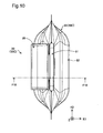
- Fig. 12 is a first perspective view illustrating the fluid container 50.
- Fig. 13 is a second perspective view illustrating the fluid container 50.
- Figs. 12 and 13 show the Z-axis, the K1-axis and the K2-axis in the state that the fluid container 50 is mounted to the mounting assembly unit 30 (in the mounting state).
- Figs. 12 and 13 also illustrate the fluid container 50 in the state of being filled with ink as a fluid before the fluid container 50 is mounted to the mounting assembly unit 30 (before the ink is consumed by the printer 10) (i.e., unused state, initial stage).
- the following describes the structure of the fluid container 50C as an example with reference to Fig. 12 and subsequent diagrams.
- the other fluid containers 50K, 50M and 50Y have the same structures as that of the fluid container 50C.
- the Z-axis, the K1-axis and the K2-axis orthogonal to one another are illustrated as follows.
- the Z-axis direction is the direction of gravity (vertical direction).
- the +Z-axis direction is upward in the direction of gravity (vertically upward), and the -Z-axis direction is downward in the direction of gravity (vertically downward).
- the Z-axis direction is also called third direction.
- the K1-axis direction along the K1-axis is horizontal direction.
- the -K1-axis direction is the connecting direction (moving direction, first direction) of the fluid container 50 when the fluid container 50 is connected to the printer 10.
- the fluid supply unit 55 described later (shown in Fig. 12 ) is moved in the connecting direction (-K1-axis direction), so that the fluid supply unit 55 (more specifically, the fluid supply assembly 57) is connected with the fluid introducing structure (fluid receiving structure) 362 provided on the printer 10, the substrate unit 58 (more specifically, the circuit board 582) is connected with the device-side terminals 381 of the electrical connection structure (shown in Fig. 6 ) provided on the printer 10.
- the +K1-axis direction is the demounting direction in which the fluid container 50 is demounted from the printer 10.
- the connecting direction is the -K1-axis direction that is the horizontal direction in this embodiment, but is not restrictive.
- the connecting direction may be any direction including a horizontal direction component.
- the K2-axis direction is the direction orthogonal to both the direction of gravity (Z-axis direction) and the K1-axis direction.
- the fluid container 50 includes the fluid container body 52 and the container body support assembly 51 attached to the fluid container body 52.
- the fluid container body 52 is configured to contain ink as the fluid.
- the fluid container body 52 is attached to the container body support assembly 51 in the state that the outer surface of the fluid container body 52 is exposed. In other words, the fluid container body 52 is not placed in a casing but is made visible from outside.
- the fluid container body 52 has the volume decreasing with a decrease in amount of the ink contained.
- a -K1-axis direction side of the fluid container 50 is expressed as first side 53fa
- a +K1-axis direction side is expressed as second side 53fb.
- the fluid container body 52 includes a first film 521, a second film 522 and a third film 523.
- the first to the third films 521 to 523 are arranged to define an inner space for containing ink.
- a side of the fluid container body 52 attached to the container body support assembly 51 is expressed as one end portion (one end portion , upper end portion) 501-side, and a side opposite to the one end portion 501 is expressed as the other end portion (the other end portion , bottom end portion) 502-side.
- One end portion side (+K2-axis direction side) of the fluid container body 52 is expressed as first side end portion (first side end portion) 503-side, and the other end portion side (-K2-axis direction side) is expressed as second side end portion (second side end portion) 504-side.
- the first film 521 and the second film 522 constitute a side surface of the fluid container body 52.
- the third film 523 constitutes a bottom surface of the fluid container body 52.
- the first film 521 and the second film 522 are arranged to face each other.
- the first film 521 and the second film 522 respectively have peripheral areas 51W partly welded. More specifically, a one end portion 501-side part, a first side end portion 503-side part and a second side end portion 504-side part of the peripheral areas 51W are welded.
- the welded parts of the first film 521 to the second film 522 are shown by cross-hatching in Figs. 12 and 13 .
- the container body support assembly 51 is welded to the one end portion 501 of the fluid container body 52 (more specifically, the one end portions of the first and the second films 521 and 522).
- the container body support assembly 51 is a member located on the one end portion 501 of the fluid container body 52.
- the welded part of the container body support assembly 51 to the first and the second films 521 and 522 is shown by the solid line single-hatching in Figs. 12 and 13 .
- a peripheral area 51Y of the third film 523 is welded to part of the peripheral areas 51W of the first and the second films 521 and 522.
- the welded part of the third film 523 to the first and the second films 521 and 522 is shown by the one-dot chain line single-hatching.
- the fluid container body 52 of the embodiment is in a form that the three films 521, 522 and 523 are bonded by, for example, welding (pouch-like form having a bottom surface).
- the first to the third films 521 to 523 are members having flexibility.
- the material used for the first to the third films 521 to 523 may be, for example, polyethylene terephthalate (PET), nylon or polyethylene.
- PET polyethylene terephthalate
- the first to the third films 521 to 523 may have layered structure formed by stacking a plurality of films made of these materials.
- an outer layer may be made of PET or nylon having excellent impact resistance
- an inner layer may be made of polyethylene having excellent ink resistance.
- a film having a deposited layer of, for example, aluminum may be included as one component member of the layered structure. This enhances the gas barrier property and suppresses, for example, a change in concentration of the ink contained in the fluid container body 52. In this manner, the material of the fluid container body 52 may be determined arbitrarily.
- the shape and the size of the fluid container body 52 may be determined arbitrarily.
- the fluid container body 52 containing black ink may be made to have the larger capacity (larger size) than that of the fluid container body 52 containing another color ink (for example, cyan ink).
- the fluid container body 52 is in the form that the first to the third films 521 to 523 are bonded by, for example, welding.
- the fluid container body 52 may alternatively be in a form that the first and the second films 521 and 522 are bonded by, for example, welding with omission of the third film 523 (pillow-like form).
- the fluid container body 52 and the operation member 53 are separate members.
- the type of the fluid container body 52 (shape, size and material) may be readily changed, while the same operation member 53 is employed.
- the shape, the size and the material of the fluid container body 52 may be determined according to the properties and the volume of the fluid to be contained in the fluid container body 52. This increases the flexibility of design.
- the container body support assembly 51 includes the operation member (handle member) 53, the fluid supply unit 55 and the substrate unit (container-side electrical connection structure) 58.
- the operation member 53 is a frame-like member open in the K1-axis direction.
- the operation member 53 has a grip part 54 located on its +Z-axis direction side end portion and the pushing part 545 located on its -Z-axis direction side (shown in Fig. 13 ).
- the grip part 54 is a part grasped by the user to support the fluid container 50.
- the grip part 54 is extended along the K2-axis direction.
- the pushing part 545 is a part pushed by the user when the fluid container 50 is connected to the printer 10.
- the pushing part 545 is a manually pushed part.
- the pushing part 545 is pushed in the -K1-axis direction (first direction), so as to move the movable support structure 40 in which the fluid container 50 is set (as shown in Fig. 9 ) in the -K1-axis direction.
- the pushing part 545 is placed on the opposite side to the side of the operation member 53 where the fluid supply unit 55 and the substrate unit 58 are placed.
- the pushing part 545 is located on the +K1-axis direction side (second side 53fb) of the fluid supply unit 55 and the substrate unit 58.
- the pushing part 545 is provided to be protruded outward (+K1-axis direction) from the operation member 53. This makes the pushing part 545 more easily distinguishable from the other part.
- the fluid supply unit 55 and the substrate unit 58 are provided on a -Z-axis direction side end portion of the operation member 53.
- the fluid supply unit 55 and the substrate unit 58 are aligned in the K2-axis direction.
- the fluid supply unit 55 has a function of supplying the ink contained in the fluid container body 52 to outside (for example, the fluid introducing structure 362 shown in Fig. 7 ).
- the substrate unit 58 has a function of electrically connecting with the device-side terminals 381 of the contact mechanism 38.
- the fluid supply unit 55 and the substrate unit 58 are provided to be protruded outward (-K1-axis direction) from the operation member 53.
- the fluid supply unit 55 and the substrate unit 58 are protruded in the same direction.
- the protruding direction of the substrate unit 58 and the protruding direction of the fluid supply unit 55 may, however, be not necessarily the same but may be different as long as the protruding directions are substantially parallel to each other.
- the substrate unit 58 and the fluid supply unit 55 are protruded from the operation member 53 toward the same side of the operation member 53 (-K1-axis direction side).
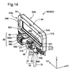
- Fig. 14 is a first perspective view illustrating part of the fluid container 50.
- Fig. 15 is a second perspective view illustrating part of the fluid container 50.
- Fig. 16 is a third perspective view illustrating part of the fluid container 50.
- Fig. 17 is a fourth perspective view illustrating part of the fluid container 50.
- Fig. 18 is a front view illustrating part of the fluid container 50.
- Fig. 19 is a rear view illustrating part of the fluid container 50.
- Fig. 20 is a top view illustrating part of the fluid container 50.
- Fig. 21 is a right side view illustrating part of the fluid container 50.
- Fig. 22 is an F18-F18 cross sectional view of Fig. 18 .
- Fig. 23 is a front view illustrating the circuit board 582.
- Fig. 14 is a first perspective view illustrating part of the fluid container 50.
- Fig. 15 is a second perspective view illustrating part of the fluid container 50.
- Fig. 17
- Fig. 24 is a view from an arrow F24 in Fig. 23 .
- Fig. 25 is an F18a-F18a partial cross sectional view of Fig. 18 .
- the fluid container body 52 of the fluid container 50 is omitted from the illustration.
- the Z-axis direction is also called “height direction”
- the K1-axis direction is also called “thickness direction”
- the K2-axis direction is also called “width direction”.
- the "height direction”, the "thickness direction” and the “width direction” of the operation member 53 correspond to the "height direction”, the "thickness direction” and the “width direction” of the fluid container 50.
- the fluid container 50 has the height, the width and the thickness in descending order.
- the operation member 53 has a first connecting part 546, a second connecting part 547, a base part 548 and an attachment part 549, in addition to the grip part 54.
- the attachment part 549 is a part which the fluid container body 52 is attached to by, for example, welding.
- the grip part 54, the first connecting part 546, the second connecting part 547 and the base part 548 are all formed in rod-like shape.
- the grip part 54, the first connecting part 546, the second connecting part 547 and the base part 548 form a frame-like member. This accordingly forms an approximately rectangular insertion space 542 to accept the user's hand in the operation member 53.
- the grip part 54 has a grip surface (support surface) 541 that is in contact with the insertion space 542.
- the grip surface 541 is a plane substantially perpendicular to the Z-axis direction in the mounting state.
- the base part 548 is extended along the K2-axis direction.
- the fluid supply unit 55 and the substrate unit 58 are attached to the base part 548. More specifically, the fluid supply unit 55 and the substrate unit 58 are interconnected via the base part 548 of the handle member 53.
- the fluid supply unit 55 and the substrate unit 58 accordingly move in conjunction with the motion of the base part 548.
- This configuration enables the user to operate the motions of the fluid supply unit 55 and a circuit board holding member 59 for connecting the fluid container 50 to the printer 10 by simply operating the motion of only one member (base part 548 in this embodiment).
- the term "interconnecting" herein means that members are connected and linked with each other to move in conjunction with each other.
- the attachment part 549 is located across the base part 548 on the opposite side to the side where the grip part 54 is located.
- the attachment part 549 is located adjacent to the base part 548.
- the attachment part 549 is extended along the K2-axis direction.
- the attachment part 549 is a part which the one end portion 501 of the fluid container body 52 (shown in Fig. 12 ) is attached to (joined with) by, for example, welding.
- the attachment part 549 includes an outlet element 550 configured to flow the ink contained in the fluid container body 52 to the fluid supply assembly 57.
- a flow path member 70 is connected with the outlet element 550, so that the ink flowing in the flow path member 70 flows through the outlet element 550 to the fluid supply assembly 57.
- the part of the attachment part 549 which the fluid container body 52 is attached to is shown by single-hatching in Figs. 18 and 19 .
- the fluid supply unit 55 includes the fluid supply assembly (fluid outlet assembly) 57 and a container-side support structure 56.
- the container-side support structure 56 and the fluid supply assembly 57 are formed as separate components, and there is a slight gap between the container-side support structure 56 and the fluid supply assembly 57.
- the fluid supply assembly 57 makes a flow of the ink contained in the fluid container body 52 to the printer 10.
- the fluid supply assembly 57 has a fluid supply port 572 on one end portion and a supply connection part 573 on the other hand.
- the fluid supply port 572 communicates with inside of the fluid container body 52 and flows out the ink contained in the fluid container body 52 to outside (printer 10).
- the fluid supply assembly 57 is extended to face in the first direction (-K1-axis direction), which is the direction intersecting with the direction of gravity (Z-axis direction), from the operation member 53 during supply of ink to the printer 10.
- the fluid introducing structure 362 (shown in Fig. 7 ) is inserted into the fluid supply port 572 in the mounting state of the fluid container 50.
- the fluid supply port 572 forms a plane (plane defined by the Z-axis direction and the K2-axis direction).
- the fluid supply port 572 is open toward the first direction (-K1-axis direction, connecting direction).
- the opening direction is a direction perpendicular to the plane formed by the fluid supply port 572 and is a direction toward the outside.
- the fluid supply port 572 is, however, not necessarily open toward the first direction but may be open in any direction including a first direction component.
- the supply connection part 573 is connected with the operation member 53.
- the fluid supply assembly 57 has a center axis CT, which is parallel to the K1-axis direction.
- the fluid supply assembly 57 is a tubular member (ring-shaped member) extended along the K1-axis direction (direction of the center axis CT). With respect to the K1-axis direction, a direction from the fluid supply port 572 toward the supply connection part 573 is the +K1-axis direction, and a direction from the supply connection part 573 toward the fluid supply port 572 is the -K1-axis direction.
- the fluid supply port 572 is located at a position that does not overlap with the operation member 53.
- the fluid supply port 572 is closed by a film 99. This suppresses leakage of ink through the fluid supply port 572 to outside before the fluid container 50 is mounted to the mounting assembly unit 30 (shown in Fig. 5 ).
- the film 99 is broken by the fluid introducing structure 362 (shown in Fig. 5 ) when the fluid container 50 is mounted to the mounting assembly unit 30.
- a positioning structure 577 is provided on the outer periphery about the center axis CT of the fluid supply assembly 57.
- the positioning structure 577 comes into contact with a supply assembly positioning structure of the fluid introducing structure 362 described later, so as to position the fluid supply assembly 57 relative to the fluid introducing structure 362, when the fluid container 50 is connected to the printer 10.
- the positioning structure 577 may be regarded as part of the fluid supply assembly 57.
- the positioning structure 577 includes a first container-side positioning member 577a, a second container-side positioning member 577b, a third container-side positioning member 577c and a fourth container-side positioning member 577d.
- the first to the fourth container-side positioning members 577a to 577d are respectively members protruded from the fluid supply assembly 57 (projection members).
- the first to the fourth container-side positioning members 577a to 577d are members extended along the K1-axis direction. Respective -K1-axis direction side end portions of the first to the fourth container-side positioning members 577a to 577d are placed near to the fluid supply port 572.
- the first container-side positioning member 577a is placed on an upper side part in the direction of gravity (+Z-axis direction side part) of the fluid supply assembly 57.
- the second container-side positioning member 577b is placed on a -K2-axis direction side part of the fluid supply assembly 57.
- the third container-side positioning member 577c is placed on a +K2-axis direction side part of the fluid supply assembly 57.
- the fourth container-side positioning member 577d is placed on a lower side part in the direction of gravity (-Z-axis direction side part) of the fluid supply assembly 57.
- the first and the fourth container-side positioning members 577a and 577d are opposed to each other in the Z-axis direction.
- the second and the third container-side positioning members 577b and 577c are opposed to each other in the K2-axis direction.
- a valve mechanism 551 is placed inside of the fluid supply assembly 57 to pen and close a fluid flow path formed by the fluid supply assembly 57.
- the valve mechanism 551 includes a valve seat (sealing element) 552, a valve element 554 and a spring 556.
- the valve seat 552, the valve element 554 and the spring 556 are placed in the fluid supply assembly 57 in this sequence from the fluid supply port 572 toward the supply connection part 573 of the fluid supply assembly 57.
- the valve seat 552 is an approximately circular member.
- the valve seat 552 is made of an elastic material such as rubber or elastomer.
- the valve seat 552 is pushed in the fluid supply assembly 57.
- the valve element 554 is an approximately cylindrical member.
- the valve element 554 is placed to close a hole (valve hole) formed in the valve seat 552 in the state before the fluid container 50 is mounted to the mounting assembly unit 30.
- the spring 556 is a compression coil spring.
- the spring 556 is arranged to bias the valve element 554 in a direction toward the valve seat 552.
- the fluid introducing structure 362 shown in Fig.
- valve element 554 presses the valve element 554 toward the supply connection part 573, so as to move the valve element 554 toward the supply connection part 573. This motion separates the valve element 554 from the valve seat 552 to set the valve mechanism 551 in the open position.
- the ink contained in the fluid container body 52 may flow out through the flow path member 70, an inner flow path 558 of the operation member 53 and the fluid supply assembly 57 to outside.
- the container-side support structure 56 positions the fluid container body 52 including the fluid supply port 572 relative to the printer 10 to some extent when the fluid container 50 is connected to the printer 10.
- the container-side support structure 56 is formed in a concave shape that is open on its +Z-axis direction side.
- the container-side support structure 56 is arranged to surround the periphery of the fluid supply assembly 57 about the center axis except the Z-axis direction part (upper part in the direction of gravity).
- the container-side support structure 56 is located at a position adjacent to the fluid supply port 572 of the fluid supply assembly 57.
- the container-side support structure 56 may be provided at a position of the operation member 53 slightly away from the fluid supply port 572.
- the container-side support structure 56 is protruded from the operation member 53 in the -K1-axis direction.
- the container-side support structure 56 is located at a predetermined position (more specifically, inside of a supply assembly support structure described later) in the movable support structure 40 when the fluid container 50 is connected to the printer 10.
- the container-side support structure 56 accordingly comes into contact with the movable support structure 40, so as to restrict the motion of the fluid supply assembly 57 and position the fluid container 50 to some extent.
- the container-side support structure 56 is also supported by the movable support structure 40, such that the fluid container body 52 hangs down by its own weight below the grip part 54 in the direction of gravity when the fluid container 50 is set in the movable support structure 40 of the mounting assembly unit 30.
- the fluid supply unit 55 has a function of supplying the ink contained in the fluid container body 52 (shown in Fig. 12 ) to the printer 10.
- the fluid supply unit 55 may thus be regarded as "fluid supply structure".
- the fluid supply unit 55 as the fluid supply structure includes the fluid supply assembly (fluid flow assembly) 57 having the fluid supply port 572 on one end portion thereof, and the container-side support structure 56.
- the fluid supply unit 55 as the fluid supply structure is attached to the one end portion part 501 of the fluid container body 52.
- the fluid supply unit 55 as the fluid supply structure is located at the one end portion 501 of the fluid container body 52.
- the substrate unit 58 includes the circuit board 582 as the container-side electrical connection structure and the circuit board holding member 59 serving as a holding member.
- the circuit board holding member 59 positions the circuit board 582 relative to the printer 10.
- the circuit board holding member 59 is integrated with the operation member 53.
- the circuit board holding member 59 is formed by integral molding with the operation member 53 to be integrated with the operation member 53.
- integrated with herein means that the circuit board holding member 59 is provided on the operation member 53 to be moved in conjunction with the motion of the operation member 53.
- the circuit board holding member 59 may be mounted to the operation member 53 by, for example, welding, so as to be integrated with the operation member 53.
- the circuit board holding member 59 is aligned with the fluid supply assembly 57 in the direction (K2-axis direction) intersecting with the first direction (-K1-axis direction).
- the circuit board holding member 59 is placed to hold (support) the circuit board 582. More specifically, the circuit board holding member 59 holds the circuit board 582 above the fluid container body 52 when the fluid container 50 is connected to the printer 10.
- the circuit board holding member 59 is a member having rigidity. More specifically, the circuit board holding member 59 has such rigidity as not to displace the circuit board 582 when the fluid container 50 is set in the movable support structure 40 of the mounting assembly unit 30.
- the circuit board holding member 59 may be made of a material such as ABS resin or polystyrene (PS).
- PS polystyrene
- the circuit board holding member 59 is formed in a concave shape that is open on the +Z-axis direction side (i.e., the side where the grip part 54 is located).
- the -K1-axis direction side of the circuit board holding member 59 is also open to receive the contact mechanism 38 therein.
- the circuit board holding member 59 has a bottom part (bottom surface) 595 (shown in Fig. 16 ), a first side wall part 592 and a second side wall part 593.
- the bottom part 595, the first side wall part 592 and the second side wall part 593 define the concave shape of the circuit board holding member 59.
- the first side wall part 592 is a wall part extended upward in the direction of gravity from a -K2-axis direction side part of the bottom part 595.
- the second side wall part 593 is a wall part extended upward in the direction of gravity from a +K2-axis direction side part of the bottom part 595.
- the first and the second side wall parts 592 and 593 are opposed to each other.
- the circuit board holding member 59 also has a placement element (placement surface) 594.
- the circuit board 582 is mounted on the placement element 594.
- the placement element 594 is located between the first side wall part 592 and the second side wall part 593.
- the placement element 594 is inclined such that its lower end portion is located on the -K-axis direction side of its upper end portion.
- the placement element 594 is inclined in a direction including a +Z-axis direction component and a -K1-axis direction component.
- the placement element 594 is located on the +Z-axis direction side of the bottom part 595.
- the first side wall part 592 has a groove 592t serving as a holding member-side positioning structure.
- the second side wall part 593 has a groove 593t serving as a holding member-side positioning structure.
- the two grooves 592t and 593t are provided on the respective sides of the circuit board 582 in the K2-axis direction across the circuit board 582.
- the two grooves 592t and 593t are in approximately rectangular parallelepiped shape.
- Part of the electrical connection unit 38 (more specifically, a device-side circuit board positioning structure) enters the two grooves 592t and 593t, so that the circuit board holding member 59 and the circuit board 582 are finally positioned relative to the device-side terminals 381.
- the circuit board 582 When the circuit board 582 comes into contact with and is thereby electrically connected with the device-side terminals 381 (shown in Fig. 7 ), the circuit board 582 is positioned relative to the device-side terminals 381 in the first direction (-K1-axis direction) and in the directions intersecting with the first direction (Z-axis direction and K2-axis direction).
- a boss groove 584 is formed on an upper end portion 586 of the +Z-axis direction side of the circuit board 582, and a boss hole 585 is formed in a lower end portion 587 on the -Z-axis direction side of the circuit board 582.
- the circuit board 582 is fixed to the placement element 594 by means of the boss groove 584 and the boss hole 585.
- the circuit board 582 includes a fluid container-side terminal group 580 provided on a surface 582fa and a storage unit 583 provided on a rear face 582fb.
- the surface 582fa and the rear face 582fb are planes.
- the fluid container-side terminal group 580 includes nine terminals 581A to 581I.
- the storage unit 420 stores information regarding the fluid container 50 (for example, the remaining amount of ink and the color of ink).
- the nine fluid container-side terminals 581A to 581I are respectively formed in approximately rectangular shape.
- the nine fluid container-side terminals 581A to 581I are arranged to form two lines Ln1 and Ln2 at different positions in the Z-axis direction that is the direction intersecting with the connecting direction (-K1-axis direction).
- the lines Ln1 and Ln2 are parallel to the K2-axis direction.
- Each of the fluid container-side terminals 581A to 581I has a contact cp on its center to come into contact with the corresponding device-side terminal 381.
- the above lines Ln1 and Ln2 may be regarded as lines formed by a plurality of contacts cp.
- the fluid container-side terminals are expressed by a symbol "581".
- the surface 582fa which the plurality of contacts cp are placed on is inclined, such that its upper end portion 587 is located on the first direction side (i.e., -K1-axis direction side, connecting direction side) of its upper end portion 586.
- a virtual plane (contact plane) TP defined by the surface of the plurality of contacts cp is inclined in the connecting direction (i.e., in the -K1-axis direction). More specifically, the virtual plane TP is inclined, such that its lower side is located on the first direction side of its upper side.
- the surface 582fa and the virtual plane TP are inclined to face in a direction including a +Z-axis direction (upward in the direction of gravity) component and a -K1-axis direction (first direction) component.
- the virtual plane (contact plane) TP is a plane which the plurality of contacts cp go through.
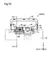
- Fig. 26 is a front view illustrating the mounting assembly unit 30.
- Fig. 27 is a first perspective view illustrating the mounting assembly unit 30.
- Fig. 28 is a second perspective view illustrating the mounting assembly unit 30.
- Fig. 27 illustrates the first state (setting state) in which the movable support structure 40 is protruded outward relative to the stationary member 35.
- Fig. 28 illustrates the second state (mounting state) in which the movable support structure 40 is placed in the stationary member 35.
- Fig. 29 is a perspective view illustrating the mounting assembly unit 30.
- Fig. 30 is an exploded perspective view illustrating the mounting assembly unit 30.
- the following describes the structure of the mounting assembly unit 30C as an example with reference to Figs. 26 to 30 .
- the other mounting assembly units 30K, 30M and 30Y have the same structures as that of the mounting assembly unit 30C.
- the movable support structure 40 is shown by single-hatching in Fig. 30 .
- the stationary member 35 has a first mounting wall 307A protruded upward in the direction of gravity and a second mounting wall 307B protruded downward in the direction of gravity.
- the first mounting wall 307A has two through holes 302H
- the second mounting wall 307B has two through holes 302H.
- Screws 302 shown in Fig. 27
- the mounting assembly unit 30 (more specifically the stationary member 35) is fixed to the surfaces 104 and 106 of the printer 10 (shown in Figs. 3 and 4 ) by means of the four screws 302. More specifically, the mounting assembly unit 30K (shown in Fig.
- the mounting assembly units 30C, 30M and 30Y (shown in Fig. 4 ) are fixed to the device third surface 106 by means of a plurality of the screws 302.
- the stationary member 35 includes the fluid introducing mechanism 36 and the contact mechanism 38.
- the fluid introducing mechanism 36 and the contact mechanism 38 are respectively fixed to the stationary member 35 to be supported on the outer wall (for example, device third surface 106) of the printer 10 via the stationary member 35.
- the fluid introducing mechanism 36 and the contact mechanism 38 are aligned in the K2-axis direction.
- the fluid introducing structure (fluid supply connection structure) 362 of the fluid introducing mechanism 36 and an electrical connection structure (device-side electrical connection structure, main body-side electrical connection structure) 382 of the contact mechanism 38 are arranged adjacent to each other in the K2-axis direction in such a manner that the fluid introducing structure 362 and the electrical connection structure 382 are visible simultaneously.
- the direction from the fluid introducing mechanism 36 toward the contact mechanism 38 is the +K2-axis direction
- the direction from the contact mechanism 38 toward the fluid introducing mechanism 36 is the -K2-axis direction.
- the Z-axis direction is also called "height direction”
- the K1-axis direction is also called “width direction”
- the K2-axis direction is also called "depth direction”.
- the fluid introducing mechanism 36 includes a fluid introducing main body 368, the fluid introducing structure 362 and a supply assembly positioning structure 364.
- the fluid supply assembly 57 of the fluid container 50 (shown in Fig. 14 ) is connected with the fluid introducing structure 362, so as to make a flow of the ink contained in the fluid container 50. More specifically, the fluid supply assembly (fluid outlet assembly) 57 of the fluid container 50 (shown in Fig. 9 ) is moved in the -K1-axis direction (first direction) accompanied with the motion of the movable support structure 40, so that the fluid introducing structure 362 is connected with the fluid supply assembly 57.
- the fluid introducing structure 362 communicates with the record head of the printer 10 through a fluid flow tube 320.
- the fluid flow tube 320 is a flexible hose.
- the outward direction of the printer 10 is the +K1-axis direction
- the inward direction of the printer 10 is the -K1-axis direction.
- the fluid introducing structure 362 and the supply assembly positioning structure 364 are provided on the fluid introducing main body 368 to be protruded in the +K1-axis direction from the fluid introducing main body 368.
- the supply assembly positioning structure 364 is arranged around the fluid introducing structure 362 about the center axis CL.
- the supply assembly positioning structure 364 positions the fluid supply assembly 57 in the direction intersecting with the K1-axis direction (according to this embodiment, the direction along the plane parallel to the Z-axis direction and the K2-axis direction) when the fluid supply assembly (fluid outlet assembly) 57 is connected with the fluid introducing structure 362.
- the supply assembly positioning structure 364 includes a first supply assembly positioning member 364a, a second supply assembly positioning member 364b, a third supply assembly positioning member 364c and a fourth supply assembly positioning member 364d.
- the first to the fourth supply assembly positioning members 364a to 364d are members protruded from the fluid introducing main body 368.
- the first supply assembly positioning member 364a is more protruded to the +K1-axis direction side than the other supply assembly positioning members 364b to 364d.
- the first supply assembly positioning member 364a is located immediately above the fluid introducing structure 362 and is protruded to the +K1-axis direction side of the fluid introducing structure 362. In other words, the first supply assembly positioning member 364a is arranged to cover the upper side of the fluid introducing structure 362.
- the first supply assembly positioning member 364a is located above the fluid introducing structure 362 in the direction of gravity (on the +Z-axis direction side of the fluid introducing structure 362).
- the second supply assembly positioning member 364b is located on the -K2-axis direction side of the fluid introducing structure 362.
- the third supply assembly positioning member 364c is located on the +K2-axis direction side of the fluid introducing structure 362.
- the fourth supply assembly positioning member 364d is located below the fluid introducing structure 362 in the direction of gravity (on the -Z-axis direction side of the fluid introducing structure 362).
- the first and the fourth supply assembly positioning members 364a and 364d are opposed to each other across the fluid introducing structure 362 in the direction of gravity.
- the second and the third supply assembly positioning members 364b and 364c are opposed to each other across the fluid introducing structure 362 in the K2-axis direction.
- the first to the fourth supply assembly positioning members 364a to 364d respectively have planes facing the fluid introducing structure 362.
- the first to the fourth container-side positioning members 577a to 577d (shown in Figs. 14 to 16 ) of the fluid supply assembly 57 come into contact with the corresponding planes. This positions the fluid supply assembly 57 relative to the fluid introducing structure 362 in the planar direction perpendicular to the K1-axis direction. More specifically, the first to the fourth container-side positioning members 577a to 577d (shown in Figs.
- the contact mechanism 38 includes the electrical connection structure (device-side electrical connection structure) 382 with a plurality of (nine in this embodiment) device-side terminals 381 and a plurality of (two in this embodiment) device-side substrate positioning structures 384 and 385.
- the device-side terminals 381 of the electrical connection structure 382 come into contact with the contacts cp of the circuit board 582 (shown in Fig. 23 ) to be electrically connected with the circuit board 582.
- This allows for communication of various information (for example, the color of ink contained in the fluid container 50 and the date of manufacture of the fluid container 50) between the storage unit 583 of the circuit board 582 (shown in Fig.
- the device-side terminals 381 are made of elastically deformable metal flat springs. More specifically, the device-side terminals 381 are formed to be elastically deformable along the plane defined by the K1-axis direction and the Z-axis direction.
- the device-side substrate positioning structures 384 and 385 are arranged across the device-side terminals 381 of the electrical connection structure 382 in the K2-axis direction (direction in which the fluid introducing mechanism 36 and the contact mechanism 38 are aligned).
- the device-side substrate positioning structures 384 and 385 serve to eventually position the circuit board 582 of the fluid container 50 relative to the electrical connection structure 382 when the fluid container 50 is mounted to the mounting assembly unit 30.
- the device-side substrate positioning structures 384 and 385 are members extended along the K1-axis direction.
- the device-side substrate positioning structures 384 and 385 start entering the corresponding holding member-side positioning structures 592t and 593t shown in Fig. 18 , before the device-side terminals 381 come into contact with the contacts cp of the circuit board 582, so that the circuit board 582 is positioned relative to the electrical connection structure 382.
- the movable support structure 40 is supported by the stationary member 35 to be movable relative to the stationary member 35 along the K1-axis direction.
- the movable support structure 40 includes a base part 41, a supply assembly support part 42 and a substrate support part 48.
- the base part 41 forms a front surface (front wall) of the movable support structure 40 located on the +K1-axis direction side.
- the base part 41 is arranged substantially parallel to the Z-axis direction and the K2-axis direction.
- the supply assembly support part 42 and the substrate support part 48 are connected with the base part 41.
- the supply assembly support part 42 and the substrate support part 48 are members extended from the base part 41 in the +Z-axis direction (upward).
- the supply assembly support structure 42 is a member serving to determine the position of the fluid container 50 (more specifically, the fluid supply assembly 57) relative to the fluid introducing structure 362.
- the supply assembly support part 42 comes into contact with the container-side support structure 56 of the fluid container 50 (shown in Fig. 14 ), so as to support the fluid supply unit 55 such that the fluid container body 52 is located below the fluid supply unit 55 in the direction of gravity.
- the supply assembly support part 42 is located at a position overlapping with the fluid introducing structure 362.
- the supply assembly support part 42 is formed in a concave shape in the -Z-axis direction.
- the supply assembly support part 42 has grooves 407 formed on both sides thereof in the K2-axis direction.
- the container-side support structure 56 enters the grooves 407, so as to restrict the motion of the fluid supply assembly 57 of the fluid container 50 and position the fluid container 50 relative to the mounting assembly unit 30 to some extent. More specifically, a plurality of planes defining the supply assembly support part 42 (for example, a first support plane 402, second support planes 403 and a third support plane 404) restrict the motion of the fluid supply assembly 57 of the fluid container 50. As shown in Fig. 27 , the second support planes 403 constituting a +K1-axis direction side wall of the supply assembly support part 42 have reinforcement ribs 403rb.
- the first support plane 402 of the supply assembly support part 42 located on the fluid introducing structure 362-side has a cut 406.
- the cut 406 is formed in a concave shape open on the +Z-axis direction side.
- the cut 406 is located at a position overlapping with the fluid introducing structure 362.
- the cut 406 is located on the +K1-axis direction side of the fluid introducing structure 362.
- an end portion of the fluid introducing structure 362 is located inside of the cut 406.
- the substrate support part 48 is a member serving to determine the position of the fluid container 50 (more specifically, the circuit board 582) relative to the contact mechanism 38.
- the substrate support part 48 is located at a position overlapping with the contact mechanism 38.
- the substrate support part 48 is formed in a concaves shape in the -Z-axis direction.
- a plurality of planes defining the substrate support part 48 (for example, a first substrate support plane 482) restrict the motion of the circuit board 582 of the fluid container 50.
- the stationary member 35 includes a first stationary member 32 and a second stationary member 33.
- a second mounting wall 307B is provided on the first stationary member 32
- a first mounting wall 307A is provided on the second stationary member 33.
- the first stationary member 32 serves as an auxiliary member to support the second stationary member 33.
- Two coil springs 39A and 39B serving as biasing members are placed between the first stationary member 32 and the movable support structure 40.
- the coil springs 39A and 39B are arranged across the contact mechanism 38 and the fluid introducing mechanism 36 placed therebetween in the K2-axis direction. When there is no necessity to distinguish between the two coil springs 39A and 39B, the coil springs are expressed by a symbol "39".
- the coil spring 39 has one end portion coming into contact with the first stationary member 32 and the other end portion coming into contact with the movable support structure 40.
- the movable support structure 40 includes a spring holder 49A inserted into the other end portion side of the coil spring 39A and a spring holder 49B inserted into the other end portion side of the coil spring 39B. When there is no necessity to distinguish between the two spring holders 49A and 49B, the spring holders are expressed by a symbol "49".
- the coil springs 39 bias the movable support structure 40 in the +K1-axis direction (second direction).
- the motion of the movable support structure 40 in the +K1-axis direction is restricted by the lock mechanism 200.
- the lock mechanism 200 is unlocked, the movable support structure 40 is pushed toward the +K1-axis direction by the biasing force of the coil springs 39, so that the mounting assembly unit 30 is made in the first state (shown in Fig. 27 ).
- Fig. 30 illustrates a spring (tension spring) 210 serving as a biasing member and a mounting element 202 to which one end portion of the spring 210 is mounted in the lock mechanism 200.
- Fig. 31 is a perspective view illustrating the engagement member 201 of the lock mechanism 200.
- the engagement member 201 includes a plate-like engagement main body 204, the mounting element 202 and a projection 206 serving as a connection structure-side engagement element.
- the engagement main body 204 has a groove 208 forming a rotating axis of the projection 206.
- a projection of the stationary member 35 described later is inserted into the groove 208.
- the projection 206 is provided to be movable in the direction of an arrow R31 including a K2-axis direction component about the groove 208 as the support point.
- the mounting element 202 is provided on a -K1-axis direction side end portion of the engagement main body 204.
- the mounting element 202 is a projection member extended from the engagement main body 204 in the +Z-axis direction.
- One end portion of the spring 210 is mounted to the mounting element 202.
- the other end portion of the spring 210 is mounted to the stationary member 35.
- the engagement member 201 is accordingly biased in the +K1-axis direction by the spring 210.
- the projection 206 is provided on a +K1-axis direction side end portion of the engagement main body 204.
- the projection 206 is extend portioned from the engagement main body 204 in the -Z-axis direction.
- Fig. 32 is a first perspective view illustrating the movable support structure 40.
- Fig. 33 is a second perspective view illustrating the movable support structure 40.
- Fig. 34 is a third perspective view illustrating the movable support structure 40.
- Fig. 35 is a fourth perspective view illustrating the movable support structure 40.
- the movable support structure 40 also has a first side surface (first side wall) 46, a second side surface (second side wall) 47, a partition surface (partition wall) 43 and a bottom (bottom wall) 49.
- the base part 41, the first side surface 46, the second side surface 47 and the partition surface 43 are members respectively extended in the +Z-axis direction from the bottom 49.
- the first side surface 46 and the second side surface 47 are opposed to each other in the K2-axis direction.
- the partition surface 43 is placed between the first side surface 46 and the second side surface 47.
- the first side surface 46, the second side surface 47 and the partition surface 43 are arranged substantially parallel to the Z-axis direction and the K1-axis direction.
- the bottom 49 is arranged substantially parallel to the K1-axis direction and the K2-axis direction.
- a locking click 462 is provided on the first side surface 46.
- a locking click 472 is provided on the second side surface 47, like the first side surface 46. The locking clicks 462 and 472 are engaged with the stationary member 35, so as to prevent the excessive motion of the movable support structure 40 in the +K1-axis direction. This prevents the movable support structure 40 from being unintentionally detached from the stationary member 35.
- a guide structure 250 is formed as part of the lock mechanism 200 on a bottom upper surface 49fa on the +Z-axis direction side of the bottom 49.
- the guide structure 250 is a groove formed in the bottom upper surface 49fa.
- the guide structure 250 is located immediately below the contact mechanism 38 (shown in Fig. 38 ).
- the guide structure 250 receives the projection 206 of the engagement member 201 and guides the projection 206 along the shape of the guide structure 250.
- the guide structure 250 has a support structure-side engagement element to be engaged with the projection 206 in the mounting state of the fluid container 50. The detailed structure of the lock mechanism 200 will be described later.
- the movable support structure 40 includes a support structure-side guide assembly 490 configured to guide the motion of the movable support structure 40 relative to the stationary member 35 in the K1-axis direction.
- the support structure-side guide assembly 490 comes into contact with the stationary member 35, so as to restrict the motion of the movable support structure 40 in the directions perpendicular to the K1-axis direction.
- the support structure-side guide assembly 490 includes a first part 491 (shown in Fig. 33 ), a second part 492 (shown in Fig. 33 ), a third part 493 (shown in Fig. 35 ), a fourth part 494 (shown in Fig. 35 ), a fifth part 495 (shown in Fig. 32 ), a sixth part 496 (shown in Fig. 32 ) and a seventh part 497 (shown in Fig. 33 ).
- the first part 491 and the second part 492 constitute an upper end surface of the movable support structure 40. More specifically, the first part 491 constitutes an upper end surface of the second side surface 47, and the second part 492 constitutes an upper end surface of the first side surface 46.
- the first part 491 and the second part 492 are arranged across the guide structure 250 placed therebetween in the K2-axis direction.
- the third part 493 and the fourth part 494 constitute a lower end surface of the movable support structure 40.
- the third part 493 and the fourth part 494 are formed on a rear surface 49fb of the bottom 49. More specifically, the third part 493 constitutes a lower end surface of the second side surface 47, and the fourth part 494 constitutes a lower end surface of the first side surface 46.
- the third part 493 and the fourth part 494 are arranged across the guide structure 250 placed therebetween in the K2-axis direction.
- the fifth part 495 and the sixth part 496 are provided on the partition surface 43. More specifically, the fifth part 495 constitutes a lower end surface of a member protruded from the partition surface 43 in the +K2-axis direction.
- the sixth part 496 is located on the -Z-axis direction side of the fifth part 495 and constitutes surfaces of members (protruded members) provided on the partition surface 43.
- the seventh part 497 is provided on the first side surface 46. More specifically, the seventh part 497 constitutes surfaces of members (protruded members) provided on the first side surface 46.
- the sixth part 496 and the seventh part 497 are arranged across the guide structure 250 placed therebetween in the K2-axis direction.
- the first part 491 to the seventh part 497 are located on at least the +K1-axis direction side end portion and the -K1-axis direction side end portion of the movable support structure 40, so as to guide the motion of the movable support structure 40 between the position relative to the stationary member 35 in the first state and the position in the second state.
- Fig. 36 is a front view illustrating the second stationary member 33.
- Fig. 37 is a first perspective view illustrating the second stationary member 33.
- Fig. 38 is a second perspective view illustrating the second stationary member 33.
- the contact mechanism 38 and the fluid introducing mechanism 36 are omitted from the illustration.
- the stationary member 35 has a first placement section 36S as a space in which the fluid introducing mechanism 36 is placed, and a second placement section 38S as a space in which the contact mechanism 38 is placed.
- the second placement section 38S is defined by a contact mechanism mounting structure 37 provided on an upper surface (upper wall) 311 of the stationary member 35.
- the contact mechanism mounting structure 37 is a frame-like member extended from the upper surface 311 in the -Z-axis direction.
- the stationary member 35 also has a first side surface (first side wall) 316, a second side surface (second side wall) 317 and a bottom surface (bottom wall) 319.
- the first side surface 316 and the second side surface 317 are members respectively extended in the -Z-axis direction from the upper surface 311.
- the first side surface 316 and the second side surface 317 are opposed to each other in the K2-axis direction.
- the contact mechanism mounting structure 37 is located between the first side surface 316 and the second side surface 317.
- the upper surface 311 and the bottom surface 319 are opposed to each other in the Z-axis direction.
- the contact mechanism mounting structure 37 has a projection 339 formed on its bottom to be inserted into the groove 208 of the engagement member 201 (shown in Fig. 31 ).
- the stationary member 35 includes a motion guide assembly 330 configured to guide the motion of the movable support structure 40 in the first direction (-K1-axis direction) or in the second direction (+K1-axis direction).
- the motion guide assembly 330 comes into contact with the support structure-side guide assembly 490 of the movable support structure 40 (shown in Figs. 32 to 35 ), so as to restrict the motion of the movable support structure 40 in the directions perpendicular to the K1-axis direction.
- the motion guide assembly 330 includes a first guide section (first guide restriction part) 331, a second guide part (second guide restriction part) 332, a third guide part (third guide restriction part) 333, a fourth guide part (fourth guide restriction part) 334, a fifth guide part (fifth guide restriction part) 335, a sixth guide part (sixth guide restriction part) 336 and a seventh guide part (seventh guide restriction part) 337.
- the first to the seventh guide parts 331 to 337 serve to restrict the motion of the movable support structure 40 relative to the stationary member 35 in the directions perpendicular to the first direction (-K1-axis direction) (i.e., directions parallel to the plane defined by the K2-axis direction and the Z-axis direction).
- the first guide part 331 and the second guide part 332 constitute the upper surface 311 of the stationary member 35.
- the first guide part 331 is located on the second side surface 317-side, and the second guide part 332 is located on the first side surface 316-side.
- the first guide part 331 and the second guide part 332 are arranged across the guide structure 250 (shown in Fig. 33 ) placed therebetween in the K2-axis direction.
- the third guide part 333 and the fourth guide part 334 constitute the bottom surface 319 (shown in Fig. 37 ) of the stationary member 35.
- the third guide part 333 is a member extended in the +K2-axis direction from the second side surface 317.
- the fourth guide part 334 is a member extended in the -K2-axis direction from the first side surface 316.
- the third guide part 333 and the fourth guide part 334 are arranged across the guide structure 250 (shown in Fig. 33 ) placed therebetween in the K2-axis direction.
- the first guide part 331 to the fourth guide part 334 are planes extended along both end portions of the stationary member 35 in the K1-axis direction.
- the fifth guide part 335 and the sixth guide part 336 are provided on a -K2-axis direction side surface 37B of the contact mechanism mounting structure 37.
- the fifth guide part 335 constitutes a bottom surface of a cut formed in the side surface 37B.
- the sixth guide part 336 constitutes a surface of a member protruded from the side surface 37B.
- the seventh guide part 337 is provided on a +K2-axis direction side surface 37A of the contact mechanism mounting structure 37.
- the seventh guide part 337 constitutes a surface of a member protruded from the side surface 37A.
- the sixth guide part 336 with the fifth guide part 335 and the seventh guide part 337 are arranged across the guide structure 250 (shown in Fig. 33 ) placed therebetween in the K2-axis direction.
- the fifth guide part 335 is extended by a predetermined length from the -K1-axis direction side end portion of the contact mechanism mounting structure 37.
- the sixth guide part 336 and the seventh guide part 337 are extended along both ends of the contact mechanism mounting structure 37 in the K1-axis direction.
- the length of the contact mechanism mounting structure 37 in the K1-axis direction is slightly smaller than the length of the stationary member 35 in the K1-axis direction.
- the motion guide assembly 330 guides the motion of the movable support structure 40 in the K1-axis direction, while restricting the motion of the movable support structure 40 in the directions perpendicular to the K1-axis direction. More specifically, the first part 491 (shown in Fig. 32 ) comes into contact with the first guide part 331, and the second part 492 (shown in Fig. 32 ) comes into contact with the second guide part 332. This restricts the motion of the movable support structure 40 in the +Z-axis direction.
- the third part 493 (shown in Fig.
- the fifth part 495 comes into contact with the fifth guide part 335, so as to restrict the motion of the movable support structure 40 in the -Z-axis direction.
- the sixth part 496 comes into contact with the sixth guide part 336, so as to restrict the motion of the movable support structure 40 in the +K2-axis direction.
- the seventh part 497 comes into contact with the seventh guide part 337, so as to restrict the motion of the movable support structure 40 in the -K2-axis direction.
- the contact mechanism 38 is placed in the second placement section 38S. More specifically, when the stationary member 35 is viewed from the +K1-axis direction side, the electrical connection structure (main body-side electrical connection structure) 382 including the device-side terminals 381 (shown in Fig. 26 ) is placed in the second placement section 38S. As shown in Fig. 36 , the electrical connection structure 382 is located between the first guide part 331 with the second guide part 332 and the third guide part 333 with the fourth guide part 334 in the Z-axis direction. The electrical connection structure 382 is also located between the sixth guide part 336 with the fifth guide part 335 and the seventh guide part 337 in the K2-axis direction. In other words, the electrical connection structure 382 is located between the guide parts 331 to 337 of the motion guide assembly 330.
- Fig. 39 is a perspective view illustrating the contact mechanism 38 mounted to the stationary member 35.
- Fig. 40 is a perspective view illustrating the contact mechanism 38.
- Fig. 41A is a perspective view illustrating the electrical connection structure 382.
- Fig. 41B is a diagram illustrating the device-side terminal 381.
- the contact mechanism 38 is mounted to the contact mechanism mounting structure 37. More specifically, the contact mechanism 38 is mounted to the stationary member 35 with a certain backlash set in the directions perpendicular to the k1-axis direction. This configuration allows the electrical connection structure 382 of the contact mechanism 38 to be displaced in the direction intersecting with the first direction (-K1-axis direction) (in this embodiment, in the direction along the plane parallel to the Z-axis direction and the K2-axis direction).
- the contact mechanism 38 includes the electrical connection structure 382 (shown in Fig. 39 ) and a holding member 388 provided to hold the electrical connection structure 382.
- the holding member 388 has a first side wall portion 394 and a second side wall portion 396.
- the first side wall portion 394 and the second side wall portion 396 are opposed to each other.
- the first side wall portion 394 is located on the -K2-axis direction side
- the second side wall portion 396 is located on the +K2-axis direction side.
- the first side wall portion 394 and the second side wall portion 396 are planes arranged substantially along the direction of gravity (Z-axis direction).
- the contact mechanism 38 includes the first device-side substrate positioning structure 384 and the second device-side substrate positioning structure 385 serving as the positioning structures (device-side substrate positioning structures).
- the first and the second device-side substrate positioning structures 384 and 385 start entering the corresponding holding member-side positioning structures 592t and 593t (shown in Fig. 18 ), before the device-side terminals 381 come into contact with the contacts cp of the circuit board 582 (shown in Fig. 23 ). This positions the contacts cp of the circuit board 582 relative to the device-side terminals 381 of the electrical connection structure 382.
- This positioning results in positioning of the fluid container-side terminals 581 relative to the device-side terminals 381 in the +K1-axis direction (first direction) and in the direction intersecting with the +K1-axis direction (direction along the plane parallel to the Z-axis direction and the K2-axis direction).
- the first and the second device-side substrate positioning structures 384 and 385 are arranged across the electrical connection structure 382 placed therebetween in the K2-axis direction.
- the first and the second device-side substrate positioning structures 384 and 385 are located at different positions but have the same shape.
- the first and the second device-side substrate positioning structures 384 and 385 are members extended along the K1-axis direction (connecting direction). As shown in Fig. 39 , the first device-side substrate positioning structure 384 is protruded outward from the first side wall portion 394. As shown in Fig. 40 , the second device-side substrate positioning structure 385 is protruded outward from the second side wall portion 396.
- the electrical connection structure 382 is held in a +K1-axis direction side part of the holding member 388.
- the electrical connection structure 382 includes a terminal holding structure 62 held by the holding member 388, nine device-side terminals 381A to 381I held by the terminal holding structure 62, and a connector 602 held by the terminal holding structure 62.
- the device-side terminals are expressed by a symbol "381".
- the terminal holding structure 62 has a surface 62fa inclined such that its lower end portion 62b is located on the -K1-axis direction side of an upper end portion 62u.
- One end portion 381a of the device-side terminal 381 (shown in Fig. 41B ) is exposed on the surface 62fa.
- the other end portion 381b of the device-side terminal 381 (shown in Fig. 41B ) is electrically connected with the connector 602.
- the connector 602 is electrically connected with the controller of the printer 10 via wiring.
- the device-side terminal 381 is a plate-like member.
- the device-side terminal 381 is elastically deformable. More specifically, the device-side terminal 381 is held by the terminal holding structure 62, such that its one end portion 381a is elastically deformed in the direction of an arrow R41 about a bent 381c.
- the direction of the arrow R41 is parallel to the K1-axis direction and the Z-axis direction.
- the plurality of device side terminals 381A to 381I constituting the device-side terminal group are arranged to form two lines LN1 and LN2 at different positions in the Z-axis direction.
- the lines LN1 and LN2 are parallel to the K2-axis direction.
- Fig. 42 is an F26-F26 cross sectional view of Fig. 26 .
- Fig. 42 also illustrates the fluid container 50.
- the coil springs 39 bias the movable support structure 40 in the second direction (+K1-axis direction).
- Engagement of the locking clicks 462 and 472 of the movable support structure 40 with the stationary member 35 restricts the excessive motion of the movable support structure 40 relative to the stationary member 35 in the +K1-axis direction. This prevents the movable support structure 40 from being unintentionally detached from the stationary member 35.
- Fig. 43 is a rear view illustrating a mounting assembly unit 30a of modified structure.
- Fig. 44 is a first diagram illustrating a restriction element 370.
- Fig. 45 is a diagram illustrating the restriction element 370.
- Fig. 46 is an F44-F44 cross sectional view of Fig. 44 .
- the fluid introducing mechanism 36 and the contact mechanism 38 are omitted from the illustration of the mounting assembly unit 30a.
- the restriction element 370 is shown by single-hatching.
- the following describes the mounting assembly unit 30a having a partly modified structure from the structure of the mounting assembly unit 30a of the first embodiment. At least part of the modification of the mounting assembly unit 30a may be applied to the mounting assembly unit 30.
- the mounting assembly unit 30a differs from the mounting assembly unit 30 mainly by addition of a restriction element 370, an abutment part 379 and a cover member 340, omission of the reinforcement ribs 403rb (shown in Fig. 27 ) and the shape of second support planes 403a.
- the cover member 340 will be described in detail in a second embodiment.
- the movable support structure 40 has the restriction element 370.
- the restriction element 370 is a sheet metal.
- the restriction element 370 is provided at a corner 401 of the movable support structure 40 between the -K1-axis direction side and the +Z-axis direction side.
- the restriction element 370 comes into contact with the fluid container 50 when the fluid container 50 is set in the movable support structure 40, so that the restriction element 370 is located in the direction of gravity above a part of the movable support structure 40 (for example, the third support plane 404) receiving the own weight (load) of the fluid container 50.
- the movable support structure 40 receives an external force F46 downward in the direction of gravity by the own weight of the fluid container 50 and an external force for the setting.
- the movable support structure 40 is going to rotate in the direction of an arrow R46 about a contact point P46 between the stationary member 35 and the movable support structure 40 on the lower side in the direction of gravity as the support point.
- the direction of the arrow R46 includes a downward component in the direction of gravity (-Z-axis direction component) intersecting with the second direction (+K1-axis direction).
- the restriction element 370 comes into contact with the abutment part 379 as part of the stationary member 35, so as to restrict the motion of the movable support structure 40 in the direction of the arrow R46. This reduces the likelihood that the movable support structure 40 is unintentionally detached from the stationary member 35. This accordingly suppresses a fall of the movable support structure 40 from the printer 10 and a resulting damage by the fall.
- the second support planes 403a have a greater thickness (length in the K1-axis direction) than that of the second support planes 403 (shown in Fig. 27 ) by omission of the reinforcement ribs 403rb (shown in Fig. 27 ).
- the second support planes 403a constitute wall surfaces of the grooves 407 in which the container-side support structure 56 of the fluid container 50 (shown in Fig. 14 ) is inserted when the fluid container 50 is set in the mounting assembly unit 30a.
- the second support plane 403a has a +Z-axis direction side end portion 403au inclined in the K2-axis direction.
- the +Z-axis direction side end portion 403au has a tapered shape. More specifically, the +Z-axis direction side end portion 403au is inclined such that a +Z-axis direction side end portion 407f of the groove 407 in which the container-side support structure 56 is inserted first has a greater length in the K1-axis direction (i.e., greater width of receiving the container-side support structure 56) than that of a -Z-axis direction side end portion 407s of the groove 407.
- This configuration causes the container-side support structure 56 (shown in Fig. 14 ) to be smoothly inserted in the grooves 407, thus enabling the fluid container 50 to be readily set in the mounting assembly unit 30a.
- Fig. 47 is a top view illustrating the mounting assembly unit 30.
- Fig. 48 is an F47-F47 cross sectional view of Fig. 47 .
- Figs. 49 to 60 are diagrams illustrating a moving pathway of the projection 206. In order to facilitate understanding, even invisible part of the engagement member 201 actually hidden and invisible is shown by the solid line as appropriate.
- the projection 206 moves in the guide structure 250 in the direction of an arrow A47.
- a pathway along which the projection 206 moves in the direction of the arrow A47 is called "moving pathway”.
- the lock mechanism 200 includes the engagement member 201, the spring 210 and the guide structure 250.
- the engagement member 201 is mounted to the stationary member 35 by means of the spring 210.
- the spring 210 has one end portion mounted to the mounting element 202 of the engagement member 201 and the other end portion mounted to a stationary member-side mounting element 351 of the stationary member 35.
- the stationary member-side mounting element 351 is located on the +K1-axis direction side and on the -K2-axis direction side of the mounting element 202 and the groove 208.
- the engagement member 201 receives a biasing force f49 by the spring 210.
- the direction of the biasing force f49 includes a +K1-axis direction component and a -K2-axis direction component.
- the biasing force f49 including the +K1-axis direction component suppresses the projection 206 from being excessively moved in the -K1-axis direction. This configuration prevents the projection 206 from being slipped off from a -K1-axis direction side end portion (inlet end portion) of the guide structure 250.
- the biasing force f49 generates a rotating force f49a applied to the projection 206.
- the direction of the rotating force f49a includes a +K2-axis direction component about the groove 208 as the support point. As shown in Fig. 50 , the biasing force f49 also generates a pressing force f50 applied to the projection 206.
- the direction of the pressing force f50 includes a component of a direction (-Z-axis direction component) in which the projection 206 is pushed against the bottom of the guide structure 250.
- the pressing force f50 reduces the likelihood that the projection 206 is detached from the guide structure 250.
- the guide structure 250 has an inlet part 252, an inlet connecting part 254, a projection wall 257, a support structure-side engagement element 258, an outlet connecting part 259 and a stepped part 256.
- the inlet part 252 is located on the most -K1-axis direction side of the guide structure 250.
- the inlet part 252 is extended in the K1-axis direction.
- the inlet connecting part 254 is connected with the inlet part 252.
- the inlet connecting part 254 is extended obliquely from the inlet part 252. More specifically, the inlet connecting part 254 is extended from the inlet part 252 in a direction including a +K1-axis direction component and a -K2-axis direction component.
- the projection wall 257 is located between the inlet connecting part 254 and the support structure-side engagement element 258 in the moving pathway.
- the projection wall 257 is a member protruded in the -K1-axis direction from a wall surface 255 located on the most +K1-axis direction side among the wall surfaces defining and forming the guide structure 250.
- the support structure-side engagement element 258 is located on the -K1-axis direction side of the wall surface 255.
- the support structure-side engagement element 258 is formed by a wall surface defining and forming the guide structure 250. In the mounting state of the fluid container 50, the support structure-side engagement element 258 is engaged with the projection 206 to restrict the motion of the projection 206.
- the outlet connecting part 259 is located between the support structure-side engagement element 258 and the inlet part 252 in the moving pathway.
- the stepped part 256 forms a different in level between the outlet connecting part 259 and the inlet connecting part 254. More specifically, the stepped part 256 forms a difference in level on the boundary between the outlet connecting part 259 and the inlet connecting part 254, such that the depth of the outlet connecting part 259 is made shallower than the depth of the inlet connecting part 254.
- the projection 206 reaches a part of the inlet connecting part 254 where the stepped part 256 is located. In this state, the projection 206 is not guided to the outlet connecting part 259 but is further guided to the inlet connecting part 254 by the stepped part 256.
- the projection 206 comes into contact with and thereby engages with the support structure-side engagement element 258.
- the engagement of the support structure-side engagement element 258 with the projection 206 restricts the motion of the projection 206 in the +K2-axis direction caused by the rotating force f49a.
- the engagement of the support structure-side engagement element 258 with the projection 206 also restricts the motion of the movable support structure 40 in the +K1-axis direction by the biasing force of the coil spring 39 (shown in Fig. 30 ).
- the state shown in Fig. 55 is the locked state by the lock mechanism 200.
- the position where the projection 206 is engaged with the support structure-side engagement element 258 is called "engagement position st".
- the lock mechanism 200 is unlocked by moving the movable support structure 40 in the -K1-axis direction.
- the user pushes the pushing part 545 of the fluid container 50 (shown in Fig. 19 ) in the -K1-axis direction, so as to move the movable support structure 40 in the -K1-axis direction.
- This causes the projection 206 to be separated away from the support structure-side engagement element 258 and unlocks the lock mechanism 200 as shown in Fig. 56 .
- the projection 206 then moves toward the outlet connecting part 259 by the rotating force f49a (shown in Fig. 49 ).
- the operation of moving the movable support structure 40 in the -K1-axis direction is stopped.
- the user stops pushing the pushing part 545 in the -K1-axis direction.
- This causes the movable support structure 40 to be moved in the +K1-axis direction by the biasing force of the coil spring 39 (shown in Fig. 30 ).
- the projection 206 moves in the outlet connecting part 259 toward the stepped part 256.
- the projection 206 as the connection structure-side engagement element moves along the guide structure 250.
- the fluid introducing structure 362 is connected with the fluid supply assembly 57 (shown in Fig. 9 ) (in the process shown in Figs. 51 to 55 ) or when the fluid introducing structure 362 is disconnected from the fluid supply assembly 57 (in the process shown in Figs. 55 to 60 )
- the fluid supply assembly 57 is supported by the movable support structure 40 (shown in Fig. 9 ).
- Fig. 61 is a first diagram illustrating a connection timing.
- Fig. 62 is an F61A-F61A partial cross sectional view of Fig. 61 .
- Fig. 63 is an F61B-F61B partial cross sectional view of Fig. 61 .
- Fig. 64 is a second diagram illustrating the connection timing.
- Fig. 65 is an F64A-F64A partial cross sectional view of Fig. 64 .
- Fig. 66 is an F64B-F64B partial cross sectional view of Fig. 64 .
- Fig. 61 is a first diagram prior to completion of mounting of the fluid container 50.
- Fig. 64 is a second diagram prior to completion of mounting of the fluid container 50.
- the fluid supply assembly 57 and the circuit board holding member 59 are arranged such that the fluid container 50 is disconnected from the mounting assembly unit 30 of the printer 10 (i.e., the fluid container 50 is demounted from the printer 10) at the following timing (demounting timing).
- the contacts cp of the circuit board 582 are separated from the device-side terminals 381 of the printer 10.
- the state that "the fluid supply assembly 57 is separated away from the fluid introducing structure 362 of the printer 10" herein means the state that the fluid supply assembly 57 moves in the demounting direction (+K1-axis direction), so as to make a communication hole 362H come out of contact with the valve seat 552 of the fluid supply assembly 57. More specifically, the state of the communication hole 362H is changed from the closed state by the valve seat 552 of the fluid supply assembly 57 to the opened state by moving the fluid supply assembly 57 in the demounting direction (+K1-axis direction). According to this embodiment, when the fluid supply assembly 57 is moved in the +K1-axis direction from the state shown in Fig.
- the communication hole 362H is an aperture formed to make the internal flow path of the fluid introducing structure 362 communicate with the outside.
- the communication hole 362H is formed in a peripheral wall of the fluid introducing structure 362.
- Fig. 67 is a first diagram illustrating the wiping effect.
- Fig. 68 is a second diagram illustrating the wiping effect.
- Fig. 67 is a diagram illustrating the state that one end portion 381a of the device-side terminal 381 starts coming into contact with the fluid container-side terminal 581 of the circuit board 582.
- Fig. 68 is a diagram illustrating the state that mounting of the fluid container 50 is completed and one end portion 381a is in contact with the contact cp of the fluid container-side terminal 581.
- moving the circuit board 582 in the connecting direction causes one end portion 381a of the device-side terminal 381 to start coming into contact with the fluid container-side terminal 581 of the circuit board 582.
- Moving the circuit board 582 further in the connecting direction causes the device-side terminal 381 to be pushed and elastically deformed by the circuit board 582.
- the elastic deformation moves one end portion 381a in the direction of the arrow R41. This motion causes one end portion 381a to reach the contact cp, while making one end portion 381a and the fluid container-side terminal 581 slightly rub against each other.
- the device-side terminal 381 and the fluid container-side terminal 581 slightly rub against each other, immediately before completion of mounting of the fluid container 50. This reduces the likelihood that the device-side terminal 381 rubs against another part of the fluid container 50 to produce some shaving in the course of mounting of the fluid container 50. More specifically, compared with a configuration that the virtual plane TP is parallel to the connecting direction (-K1-axis direction), the inclined configuration of this embodiment reduces the likelihood that the circuit board 582 is scraped off by the device-side terminal 381 and accordingly reduces the likelihood that shaving adheres to the contact cp.
- the inclined configuration of the virtual plane TP increases the moving distance of the device-side terminal 381 from the position of contact of the device-side terminal 381 with the circuit board 582 to the position of contact of the device-side terminal 381 with the contact cp.
- the device-side terminal 381 reaches the contact cp with rubbing against the surface 582fa of the circuit board 582 and thereby removes the dust adhering to the device-side terminal 381 or the circuit board 582 from the contact cp. This ensures good electrical continuity between the contacts cp and the device-side terminals 381.
- FIG. 69 is a cross sectional diagram illustrating part of the mounting assembly unit 30 and the fluid container 50 in the mounting state. This cross section includes a contact area where the device-side terminals 381 are in contact with the fluid container-side terminals 581 (more specifically, the contacts cp) in the mounting state of the fluid container 50.
- the fluid container 50 receives an external force Fs from the contact mechanism 38.
- the external force Fs is a force applied to the circuit board 582 by the device-side terminals 381 of the contact mechanism 38.
- the external force Fs is a force applied substantially perpendicularly to the surface 582fa of the circuit board 582.
- the external force Fs includes a force component Fs1 in the +K1-axis direction and a force component Fs2 in the -Z-axis direction. More specifically, the external force Fs applied from the device-side terminals 381 to the fluid container-side terminals 581 includes a component in the +K1-axis direction which is the demounting direction.
- This external force Fs including the +K1-axis direction component is generated by the inclined configuration of the surface 582fa (virtual plane TP) in a direction including a -K1-axis direction component.
- the surface 582fa (virtual plane TP) is inclined in a direction including a -K1-axis direction component and a -Z-axis direction component.
- the inclination of the virtual plane TP with respect to the first direction facilitates generation of the force component Fs1 having a vector component in the second direction, compared with a configuration that the contacts cp are arranged to make the virtual plane TP parallel to the first direction and are brought into contact with the electrical connection structure 382 by a force in a direction perpendicular to the first direction (i.e., in the -Z-axis direction). Accordingly, this enables the fluid container 50 to be readily moved in the demounting direction in the course of unlocking the lock mechanism 200 and demounting the fluid container 50 and makes the contacts cp more easily separated from the electrical connection structure 382. This results in readily demounting the fluid container 50 from the mounting assembly unit 30.
- Fig. 70 is a rear view illustrating the mounting assembly unit 30 in the mounting state.
- Fig. 71 is an F70-F70 cross sectional view of Fig. 70 .
- an area where the contacts cp are formed is located in a third direction (Z-axis direction) which passes through the engagement position st and is orthogonal to the second direction (+K1-axis direction).
- the area where the contacts cp are formed corresponds to the surface 582fa of the circuit board 582 in this embodiment. More specifically, as shown in the lower diagram of Fig. 71 , when the fluid container 50 in the mounting state is viewed downward in the direction of gravity, the engagement position st at least partly overlaps with the circuit board 582. In the mounting state, the movable support structure 40 configured to support the fluid container 50 is biased in the +K1-axis direction by the coil spring 39.
- Locating the projection 206 at the engagement position st restricts the motion of the movable support structure 40 by the biasing force of the coil spring 39.
- the biasing force of the coil spring 39 accordingly produces a force of rotating the movable support structure 40 in the direction of an arrow R71 about the engagement position st (more specifically, the wall of the guide structure 250 coming into contact with the projection 206).
- the direction of the arrow R71 is a direction including a K1-axis direction component and a K2-axis direction component.
- the engagement position st overlaps with the area where the contacts cp are formed (i.e., the surface 582fa of the circuit board 582). According to this embodiment, the engagement position st overlaps with the contacts cp. This positional relationship suppresses a deviation of the contacts cp from their designed position even when the movable support structure 40 is rotated in the direction of the arrow R71 about the engagement position st. This accordingly ensures the good electrical continuity between the contacts cp and the electrical connection structure 382 in the mounting state.
- a preferable positional relationship is that the engagement position st at least partly overlaps with an area r582 defined by a minimum convex polygon encompassing a plurality of the fluid container-side terminals 581. This positional relationship further suppresses a deviation of the contacts cp from their designed position.
- Fig. 72 is a side view illustrating the state that the fluid container 50 is set in the movable support structure 40 of the mounting assembly unit 30.
- Fig. 73 is a front view illustrating the state that the fluid container 50 is set in the movable support structure 40 of the mounting assembly unit 30.
- Fig. 74 is an F72-F72 cross sectional view of Fig. 72 .
- Fig. 75 is an F73-F73 cross sectional view of Fig. 73 .
- Fig. 76 is side view illustrating the state that mounting (connection) of the fluid container 50 to the mounting assembly unit 30 is completed.
- Fig. 77 is an F76-F76 cross sectional view of Fig. 76 .
- the state of the mounting assembly unit 30 shown in Fig. 72 is the second state like Fig. 6 .
- the state of the mounting assembly unit 30 shown in Fig. 76 is the first state like Fig. 7 .
- the fluid container body 52 is supported such that the fluid supply unit 55 and the substrate unit 58 are located above the fluid container body 52 in the direction of gravity (i.e., on the +Z-axis direction side of the fluid container body 52). More specifically, as shown in Fig. 74 , a bottom 569 of the container-side support structure 56 comes into contact with the third support plane 404 of the supply assembly support part 42. This restricts the motion of the fluid container 50 downward in the direction of gravity (i.e., in the -Z-axis direction). This configuration supports the -K2-axis direction side of the fluid container body 52.
- the fluid supply unit 55 and the substrate unit 58 are located above the fluid container body 52 in the direction of gravity (i.e., on the +Z-axis direction side of the fluid container body 52) to support the fluid container body 52. More specifically, the bottom part 595 of the circuit board holding member 59 coming into contact with a bottom 357 of the stationary member 35 restricts the motion of the fluid container 50 downward in the direction of gravity (i.e., in the -Z-axis direction).
- the fluid container 50 is supported through such restriction of the motion of the fluid container 50 downward in the direction of gravity by the fluid supply unit 55 and the substrate unit 58.
- the bottom 357 of the stationary member 35 starts coming into contact with the circuit board holding member 59, prior to completion of the connection of the fluid container 50 to the movable member 40 after the fluid container 50 is set in the movable member 40 and is moved in the connecting direction.
- the bottom part 595 of the circuit board holding member 59 rotates in the direction of an arrow R74 and comes into contact with a device-side rotation restricting part 487 of the movable member 40.
- This configuration restricts the rotation of the circuit board holding member 59 in the direction of the arrow R74 about the fluid supply assembly 57.
- the bottom part 595 is thus also called rotation restricting part 595.
- the fluid supply assembly 57 and the container-side electrical connection structure 58 are arranged in the positional relationship such that the contacts cp of the circuit board 582 are separated away from the printer 10, prior to the fluid supply assembly 57 in the course of disconnection of the fluid container 50 from the printer 10.
- the fluid container body 52 may be unintentionally pushed and make the fluid scattered from the fluid supply assembly 57 to outside.
- the scattered ink may adhere to the contact parts and may cause an electrical problem such as a short circuit.
- the fluid supply unit 55 including the fluid supply assembly 57 is located at the one end portion 501-side of the fluid container body 52, i.e., above the fluid container body 52 in the direction of gravity as shown in Figs. 12 and 14 . Accordingly, the configuration of the fluid container 50 of the above embodiment causes the contacts cp of the circuit board 582 to be separated away from the printer 10, prior to the fluid supply assembly 57, in the course of disconnection of the fluid container 50 from the printer 10. This reduces the likelihood of the electrical problem described above.
- the fluid container 50 includes the handle member 53 linked with the fluid supply unit 55 including the fluid supply assembly 57 and with the container-side electrical connection structure 58.
- This configuration ensures the easy operation of the fluid container 50 by using the handle member 53.
- the user may grasp the handle member 53 and move the fluid container 50 to readily set the fluid container 50 in the mounting assembly unit 30.
- the grip part 54 of the handle member 53 is formed in an approximately rectangular frame-like shape but may be formed in an approximate C shape or in an approximate T shape.
- the fluid supply connection unit (mounting assembly unit) 30 of the printer 10 has the connection mechanism for connecting the fluid container 50 to the printer 10, which includes, for example, the movable support structure 40, the guide structure 250 and the connection structure-side engagement element 206.
- the fluid container 50 accordingly does not need to have any complicated connection mechanism and has the simplified structure. This facilitates disposal of the fluid container 50 after ink consumption.
- the connection structure-side engagement element 206 is engaged with the guide structure 250 of the fluid supply connection unit 30.
- this configuration of the embodiment does not need the connection structure-side engagement element 206 to be engaged with the guide structure 250 of the casing in the course of connection of the fluid container 50. This accordingly ensures the easy and secure connection of the fluid container 50 with the printer 10.
- the stationary structure 35 includes the motion guide assembly 330 configured to guide the motion of the movable support structure 40 in the first direction (-K1-axis direction9 or in the second direction (+K1-axis direction).
- the fluid container 50 accordingly does not need to have any complicated mechanism for guiding in the first direction or in the second direction and has the simplified structure.
- the mounting assembly unit (fluid supply connection unit) 30 includes the main body-side electrical connection structure 382 located between the parts of the motion guide assembly 330.
- the fluid container 50 has the contacts cp arranged to come into contact with the main body-side electrical connection unit 382 of the printer 10. Since the main body-side electrical connection structure 382 is located between the parts of the motion guide assembly 330, the contacts cp are smoothly connected with the main body-side electrical connection structure 382 by guiding the motion of the fluid container 50 supported on the movable support structure 40 by the motion guide assembly 330.
- the fluid container 50 includes the pushing part 545 located on the second side 53fb opposite to the side on which the fluid supply assembly 57 is placed across the operation member 53 and configured to push the fluid supply assembly 57 in the first direction (-K1-axis direction).
- the fluid container 50 is thus readily movable in the first direction by pressing the pushing part 545. This makes the fluid supply assembly 57 more easily connected with the mounting assembly unit 30.
- Fig. 78 is a diagram illustrating a fluid container 50b according to a second embodiment.
- Fig. 79 is a perspective view illustrating the fluid container 50b.
- Fig. 80 is a side view illustrating the fluid container 50b.
- the fluid container 50b of the second embodiment differs from the fluid container 50 of the first embodiment (shown in Fig. 18 ) by that the the fluid container 50b additionally has a container-side identification member 72. Otherwise the structure of the fluid container 50b of the second embodiment is similar to that of the first embodiment.
- the like components are expressed by the like symbols to those of the first embodiment and are not specifically described herein.
- the container-side identification member 72 is used to identify whether a right type of (in this embodiment, a right ink color of) the fluid container 50 is mounted.
- the container-side identification member 72 is made of at least one projection 72A provided on the bottom part 595 of the circuit board holding member 59.
- the projection 72A is located on a -K1-axis direction side end portion of the bottom part 595.
- the container-side identification member 72 has a different pattern specified by the number and the positions of the projections 72A for each of different types of fluid containers 50b (fluid containers 50C, 50M, 50Y and 50K containing different color inks).
- Fig. 81 is a first perspective view illustrating a mounting assembly unit 30b of the second embodiment.
- Fig. 82 is a second perspective view illustrating the mounting assembly unit 30b of the second embodiment.
- Fig. 83 is a side view illustrating the mounting assembly unit 30b.
- Fig. 84 is a diagram illustrating the state that the fluid container 50b is set in the mounting assembly unit 30b shown in Fig. 81 .
- Fig. 85 is a diagram illustrating the state that the fluid container 50b is mounted to the mounting assembly unit 30b shown in Fig. 82 .
- Fig. 81 illustrates the first state that the movable support structure 40 is protruded outward relative to a stationary member 35b.
- the mounting assembly unit 30b of the second embodiment differs from the mounting assembly unit 30 of the first embodiment (shown in Fig. 27 ) by that the mounting assembly unit 30b includes a cover member 340, a device-side upper restriction element 345 and a device-side identification member 75 (shown in Fig. 82 ). Otherwise the structure of the mounting assembly unit 30b of the second embodiment is similar to that of the first embodiment.
- the like components are expressed by the like symbols to those of the first embodiment and are not specifically described herein.
- the cover member 340 is provided on a first wall (first side surface) 352 and a second wall (second side surface) 353 arranged to intersect with an upper wall (upper surface) 354 of the stationary member 35b.
- the first wall 352 is located on the +K2-axis direction side
- the second wall 353 is located on the -K2-axis direction side.
- the cover member 340 is provided to cover at least part of the handle member 53 when the fluid container 50b is connected to the mounting assembly unit 30b.
- the cover member 340 includes a first cover part 340A and a second cover part 340B.
- the first cover part 340A is provided on the first wall 352 to be protruded from the first wall 352 toward the +K1-axis direction side (front wall 356-side).
- the second cover part 340B is provided on the second wall 353 to be protruded from the second wall 353 toward the +K1-axis direction side (front wall 356-side).
- the device-side upper restriction element 345 is provided on the stationary member 35b. More specifically, the device-side upper restriction element 345 is provided on a front wall 356 constituting a +K1-axis direction side surface of the stationary member 35b.
- the device-side upper restriction element 345 includes a first upper restriction part 345A and a second upper restriction part 345B.
- the first upper restriction part 345A and the second upper restriction part 345B are arranged across the fluid introducing mechanism 36 in the K2-axis direction.
- the first upper restriction part 345A and the second upper restriction part 345B come into contact with a +Z-axis direction-side end surface (upper end surface) 56u (shown in Fig. 79 ) of the container-side support structure 56, so as to restrict the motion of the container-side support structure 56 in the +Z-axis direction, when the fluid container 50b is connected to the mounting assembly unit 30b.
- the device-side identification member 75 is provided on the stationary member 35b.
- the device-side identification member 75 is formed immediately below the contact mechanism 38.
- the device-side identification member 75 is made of at least one projection 75A.
- the device-side identification member 75 has a different pattern specified by the number and the positions of the projections 75A for each of different types (more specifically, each of different types of the fluid containers 50b to be mounted). In the case that a right type of the fluid container 50b is mounted to the mounting assembly unit 30b, the device-side identification member 75 and the container-side identification member 72 do not collide with each other but are fit in each other.
- the device-side identification member 75 and the container-side identification member 72 collide with each other to interfere with further motion of the fluid container 50b in the connecting direction (-K1-axis direction). This configuration reduces the likelihood that a wrong type of the fluid container 50b is mounted to the mounting assembly unit 30b.
- Fig. 86 is a diagram illustrating a connection timing.
- Fig. 87 is an F86A-F86A partial cross sectional view of Fig. 86 .
- Fig. 88 is an F86B-F86B partial cross sectional view of Fig. 86.
- Fig. 86 illustrates the state that the fluid container 50b is set in the movable support structure 40 and is pushed and moved in the connecting direction (-K1-axis direction) to start fitting between the container-side identification member 72 and the device-side identification member 75.
- fitting between the container-side identification member 72 and the device-side identification member 75 starts, prior to a start of connection of the fluid introducing structure 362 with the fluid supply assembly 57.
- This configuration reduces the likelihood that a wrong type of the fluid container 50b is mounted to the mounting assembly unit 30b and thereby reduces the likelihood that the wrong color ink is introduced through the fluid introducing part 362.
- fitting between the container-side identification member 72 and the device-side identification member 75 starts, prior to a start of the contact of the device-side terminals 381 with the circuit board 582.
- Fitting between the container-side identification member 72 and the device-side identification member 75 is not made in the course of setting the fluid container 50b in the movable support structure 40 of the mounting assembly unit 30b but is made in the course of moving the fluid container 50b in the connecting direction after setting.
- This configuration prevents the container-side identification member 72 and the device-side identification member 75 from colliding with each other in the course of setting, thus reducing the likelihood that the fluid container 50b is not set in a proper attitude in the movable support structure 40. Accordingly this reduces the occurrence of various problems that may arise by the failure in setting the fluid container 50b in a proper attitude in the movable support structure 40.
- this reduces the problem that the container-side identification member 72 and the device-side identification member 75 collide with each other in the course of setting and the fluid container 50b falls off from the movable support structure 40. This also reduces the likelihood that the fluid container 50b or the mounting assembly unit 30b is damaged by collision of the fluid container 50b with part of the stationary member 35b in the course of moving the fluid container 50b in the connecting direction after setting.
- Fig. 89 is a cutaway drawing of Fig. 84 .
- Fig. 90 is a perspective view illustrating the mounting assembly unit 30b and the fluid container 50b.
- Fig. 91 is a cutaway drawing of Fig. 90 .
- Fig. 92 is a perspective view illustrating the mounting unit 30b and the fluid container 50b.
- Fig. 93 is a cutaway drawing of Fig. 92 .
- Fig. 90 illustrates the state that the fluid container 50b is pushed and moved in the connecting direction and the device-side upper restriction element 345 (shown in Fig. 82 ) approaches the upper end surface 56u (shown in Fig. 78 ) of the container-side support structure 56.
- Fig. 92 illustrates the state that connection of the fluid container 50b is completed.
- the upper end surface 56u moves toward the device-side upper restriction element 345.
- the container-side support structure 56 reaches the position where the device-side upper restriction element 345 is located with respect to the connecting direction, substantially simultaneously with starting the connection of the fluid supply assembly 57 to the fluid introducing structure 362. As shown in Fig. 89 , as the fluid container 50b is pushed and moved in the connecting direction (-K1-axis direction), the upper end surface 56u moves toward the device-side upper restriction element 345. As shown in Fig. 91 , the container-side support structure 56 reaches the position where the device-side upper restriction element 345 is located with respect to the connecting direction, substantially simultaneously with starting the connection of the fluid supply assembly 57 to the fluid introducing structure 362. As shown in Fig.
- the upper end surface 56u of the container-side support structure 56 comes into contact with the device-side upper restriction element 345, so that the operation of connecting the fluid supply assembly 57 with the fluid introducing structure 362 proceeds under restriction of the motion of the container-side support structure 56 upward in the direction of gravity (+Z-axis direction). This ensures the good connection of the fluid supply assembly 57 with the fluid introducing structure 362.
- the handle member 53 is covered by the cover member 340 in the state that the fluid container 50b is connected to the mounting assembly unit 30b.
- the first connecting part 546 and the second connecting part 547 of the handle member 53 are placed inside of the cover member 340 so as to be covered by the cover member 340.
- This configuration suppresses the handle member 53 from being operated by the user in the connecting state of the fluid container 50b. Covering the handle member 53 by the cover member 340 also reduces the likelihood that the handle member 53 is damaged.
- Fig. 94 is a front view illustrating the mounting assembly unit 30b.
- Fig. 95 is a front view illustrating the stationary member 35b in the mounting state.
- a symbol “331R” shown in Fig. 94 indicates an area where the first guide part 331 (shown in Fig. 36 ) is located when the mounting assembly unit 30b is viewed from the +K1-axis direction side.
- a symbol “332R” shown in Fig. 94 indicates an area where the second guide part 332 (shown in Fig. 36 ) is located when the mounting assembly unit 30b is viewed from the +K1-axis direction side.
- a symbol “333R” shown in Fig. 94 indicates an area where the second guide part 333 (shown in Fig.
- a symbol "334R" shown in Fig. 94 indicates an area where the fourth guide part 334 (shown in Fig. 36 ) is located when the mounting assembly unit 30b is viewed from the +K1-axis direction side.
- An area inside of a convex polygon (rectangle in this embodiment) formed by connecting the first guide part 331 to the fourth guide part 334 when the mounting assembly unit 30b is viewed from the +K1-axis direction side (from the second direction side) is called area 330R defined by the plurality of guide restriction parts 331 to 334.
- the area 330R is an area inscribed in the first to the fourth guide parts 331 to 334.
- the fluid supply assembly 57 is supported on the movable support structure 40 and the fluid supply structure 55 is connected with or disconnected from the mounting assembly unit 30b, at least part of the pushing part 545 is located inside of the area 330R.
- This configuration enables the operation of connecting the fluid supply structure 55 with the mounting assembly unit 30b or the operation of disconnecting the fluid supply structure 55 from the mounting assembly unit 30b to be performed smoothly via the motion guide assembly 330 (shown in Fig. 36 ) by pushing the pushing part 545.
- Figs. 96 to 98 are diagrams illustrating modifications of terminal geometry of the circuit board. Circuit boards 582a to 582c of these modifications differ from the circuit board 582 shown in Fig. 23 by only the surface geometry of the fluid container-side terminals 581A to 581H. In the circuit boards 582a and 582b of Figs. 96 and 97 , the individual terminals do not have the approximately rectangular shape but irregular shapes. In the circuit board 582c of Fig. 98 , the nine fluid container-side terminals 581A to 581H are aligned. These circuit boards 582a to 582c have the same arrangement of the contacts cp, which come into contact with the device-side terminals 381 (shown in Fig. 41A ) corresponding to the respective fluid container-side terminals 581A to 581H, as that of the circuit board 582 shown in Fig. 23 . As long as the arrangement of the contacts cp is fixed, the individual terminals may have any surface geometry.
- the term "plane” is used in a broad sense including both a virtual plane (also called non-real plane) and a real plane.
- the contact plane TP defined by three or more contacts comprised of the contacts cp included in the line Ln1 and the contacts cp included in the line Ln2 shown in Fig. 23 accordingly means both a virtual plane and a real plane inclined in a predetermined direction.
- Fig. 99 is a diagram illustrating one example of the virtual contact plane TP inclined in a predetermined direction.
- Fig. 100 is a diagram of Fig. 99 viewed from the -K2-axis direction.
- Fig. 99 illustrates a circuit board 582d with a step S between the line Ln1 and the line Ln2 as one example.
- the virtual contact plane TP is defined by connecting the contact cp of the terminal 581D included in the line Ln2 and the contacts cp of the terminals 581H and 581I included in the line Ln1.
- the virtual contact plane TP defined by the respective contacts cp is inclined in a predetermined direction.
- the virtual contact plane TP is inclined in a direction including a +Z-axis direction (upward in the direction of gravity) component and a -K1-axis direction (first direction) component.
- Fig. 101 is a diagram illustrating another example of the virtual contact plane TP inclined along a predetermined direction.
- a circuit board 582e shown in Fig. 101 is made of a bendable (flexible) film. Since the circuit board 582e is bendable, the virtual contact plane TP is inclined along the predetermined direction even without formation of the step S shown in Figs. 99 and 100 .
- an inclined surface defined by the contacts cp (including both a virtual contact surface TP and a real contact surface TP) needs to be inclined in the direction including the +Z-axis direction (upward in the direction of gravity) component and the -K1-axis direction (first direction) component at least in the mounting state.
- Any of the configurations other than those described above may have the similar advantageous effects to those of the above embodiment, as long as the virtual or the real contact plane TP is inclined.
- Fig. 102 is a diagram illustrating a fluid container-side terminal member 582f having the fluid container-side terminals 581.
- Fig. 103 is a diagram illustrating the state of contact between the fluid container-side terminal member 582f and the device-side terminals 381 (shown in Fig. 41A ).
- the fluid container 50 may have the fluid container-side terminal member 582f configured to come into contact with the device-side terminals 381 and thereby to be electrically connectable with the electrical connection structure 382, instead of the circuit board 582 of the above embodiment.
- the fluid container-side terminal member 582f is a member protruded from the placement element 594. As shown in Fig.
- an end face of the fluid container-side terminal member 582f forms a plurality of (nine in the illustrated example) fluid container-side terminals 581.
- the fluid container-side terminals 581 have contacts cp arranged to come into contact with the device-side terminals 381 in the mounting state of the fluid container 50.
- the virtual plane TP defined by the plurality of contacts cp is inclined in the direction including the +Z-axis direction (upward in the direction of gravity) component and the -K1-axis direction (first direction) component, like the above embodiment. This configuration also has the similar advantageous effects to those of the above embodiment.
- the container-side electrical connection structure 58 includes the circuit board 582.
- the container-side electrical connection structure 58 may have any configuration including the contacts cp arranged to come into contact with the device-side electrical connection structure 382.
- the circuit board 582 may not have the storage unit 583.
- the container-side electrical connection structure 58 may have a contact of a terminal used for detection of mounting and demounting of the fluid container 50.
- the container-side electrical connection structure 58 may have a circuit board assembly including a flexible cable, such as a flexible printed circuit board (FPC). This circuit board assembly may have contacts arranged on its one end portion to come into contact with the device-side electrical connection structure 382. The other end portion of the circuit board assembly may be connected, for example, with a reset device.
- This modified configuration may be employed, instead of the circuit board 582 or in addition to the circuit board 582.
- the guide structure 250 is a groove as shown in Fig. 33
- the connection structure-side engagement element 206 (shown in Fig. 31 ) guided by the guide structure 250 is a projection.
- the guide structure 250 and the connection structure-side engagement element 206 may have any geometries that enable the connection structure-side engagement element 206 to be guided by the guide structure 250 and to be engaged with the guide structure 250 at the engagement position st.
- the guide structure 250 may be formed in a convex shape
- the connection structure-side engagement element 206 may be formed in a groove-like shape to receive the convex guide structure 250 therein.
- the fluid container body 52 is made of a material having flexibility. This is, however, not restrictive, and the fluid container body 52 may be made of any material that enables the fluid container body 52 to contain a fluid.
- the fluid container body 52 may be partly made of a material having flexibility or may be made of a hard material that substantially does not change its volume irrespective of the consumption of the fluid. Forming at least part of the fluid container body 52 of the material having flexibility causes the volume of the fluid container body 52 to be varied according to the amount of ink contained in the fluid container body 52.
- the connecting direction of the fluid container 50 with the mounting assembly unit 30 is the horizontal direction (K1-axis direction).
- the connecting direction may be any direction including a first direction (K1-axis direction) component.
- the connecting direction may be a direction including a -Z-axis direction component and a -K1-axis direction component.
- the movable support structure 40 is also moved in a direction corresponding to the connecting direction of the fluid container 50.
- the present invention is not limited to the inkjet printer or its fluid container 50 but is also applicable to any printing device (fluid consuming device) configured to eject another fluid but ink and a fluid container configured to contain another fluid.
- the invention may be applied to any of various fluid consuming devices and their fluid containers:
- the "droplet” herein means the state of fluid ejected from the fluid consuming device and may be in a granular shape, a teardrop shape or a tapered threadlike shape.
- the "fluid” herein may be any material ejectable by the fluid consuming device.
- the “fluid” may be any material in the liquid phase.
- liquid-state materials of high viscosity or low viscosity, sols, aqueous gels and other liquid-state materials including inorganic solvents, organic solvents, solutions, liquid resins and liquid metals (metal melts) are included in the "fluid".
- the "fluid” is not limited to the liquid state as one of the three states of matter but includes solutions, dispersions and mixtures of the functional solid material particles, such as pigment particles or metal particles, solved in, dispersed in or mixed with a solvent.
- Typical examples of the fluid include ink described in the above embodiment and liquid crystal.
- the ink herein includes general water-based inks and oil-based inks, as well as various fluid compositions, such as gel inks and hot-melt inks.
Landscapes
- Chemical & Material Sciences (AREA)
- Dispersion Chemistry (AREA)
- Engineering & Computer Science (AREA)
- Mechanical Engineering (AREA)
- Ink Jet (AREA)
- Quick-Acting Or Multi-Walled Pipe Joints (AREA)
Abstract
Description
- This application claims priority to Japanese Patent Application No.
2014-051620 filed on March 14, 2014 - The present invention relates to a technique of supplying a fluid to a fluid consuming device.
- A known configuration of a fluid container has a casing and a fluid-containing bag placed in the casing (for example,
JP 2005-238815A - The above technique of
JP 2005-238815A - This problem is not limited to the fluid container provided to supply ink to the printer but is commonly found in any fluid container configured to supply a fluid to a fluid consuming device.
- An object of the invention is accordingly to provide a technique that facilitates connection of a fluid container with a fluid consuming device and disconnection of the fluid container from the fluid consuming device by the simple configuration. Other needs with respect to the prior art include cost reduction, resource saving, easy manufacture and improvement of usability.
- In order to solve at least part of the problems described above, the invention may be implemented by aspects described below.
- (1) According to one aspect of the invention, there is provided a fluid container detachably connectable with a fluid consuming device. This fluid container comprises: a fluid container body at least partly made of a material having flexibility and configured to contain a fluid; a fluid supply structure located at one end portion of the fluid container body and configured to be connectable with a fluid introducing structure provided in the fluid consuming device; and a container-side electrical connection structure linked with the fluid supply structure and configured to have a contact arranged to come into contact with a device-side electrical connection structure provided in the fluid consuming device. The fluid supply structure and the container-side electrical connection structure are arranged in a positional relationship such that the contact of the container-side electrical connection structure is separated away from the fluid consuming device, prior to the fluid supply structure, when the fluid container is disconnected from the fluid consuming device.
- In the course of disconnection of the fluid container from the fluid consuming device, the fluid container body may be unintentionally pushed and make the fluid scattered from the fluid supply structure to outside. In this case, when the contact of the container-side electrical connection structure is in contact with the device-side electrical connection structure of the fluid consuming device, the scattered ink may adhere to the contact part and may cause an electrical problem such as a short circuit. In the fluid container of this aspect, however, the fluid supply structure is located at one end portion of the fluid container. Accordingly, the configuration of the fluid container causes the contact of the container-side electrical connection structure to be separated away from the fluid consuming device, prior to the fluid supply structure, in the course of disconnection of the fluid container from the fluid consuming device. This reduces the likelihood of the electrical problem described above.
- (2) In the fluid container of the above aspect, the container-side electrical connection structure may have a plurality of the contacts, surface of the plurality of contacts defines a virtual plane, and the virtual plane may be inclined with respect to a connecting direction of the fluid container with the fluid consuming device.
- In the fluid container of this aspect, the virtual plane is inclined. Compared with a configuration that the virtual plane is arranged parallel to the connecting direction, the inclined configuration of this aspect reduces the likelihood that some shaving produced by scraping off the container-side electrical connection structure by the device-side electrical connection structure adheres to the contact. Compared with a configuration that the virtual plane is arranged perpicular to the connecting direction, the inclined configuration of this aspect increases the moving distance of the device-side electrical connection structure from the position of contact of the device-side electrical connection structure with the container-side electrical connection structure to the position of contact of the device-side electrical connection structure with the contact. The device-side electrical connection structure accordingly comes into contact with the contact, while rubbing against the surface of the container-side electrical connection structure. This removes the dust adhering to the device-side electrical connection structure or the container-side electrical connection structure from the contact. This ensures good electrical continuity between the contact and the device-side electrical connection structure.
- (3) The fluid container of the above aspect may further comprise a handle member linked with the fluid supply structure and the container-side electrical connection structure.
- The fluid container of this aspect uses the handle member to facilitate the operation of the fluid container.
- (4) In the fluid container of the above aspect, at least part of the handle member may be covered by a cover member provided on the fluid consuming device in a state that the fluid container is connected with the fluid consuming device.
- The fluid container of this aspect suppresses an operation of the handle member in the connecting state. This also reduces the likelihood that the handle member is damaged.
- (5) According to another aspect of the invention, there is provided a fluid container detachably connectable with a fluid consuming device. The fluid container comprises a fluid supply structure configured to be connectable with a fluid supply connection unit of the fluid consuming device. The fluid supply connection unit comprises: a stationary structure supported by a casing of the fluid consuming device and configured to have a fluid introducing structure which the fluid supply structure is connected with; and a movable support structure supported by the stationary structure and configured to be movable in a first direction and in a second direction with supporting the fluid supply structure of the fluid container, the first direction being a direction approaching the stationary structure, the second direction being a direction moving away from the stationary structure. The movable support structure includes a guide structure having a support structure-side engagement element. The stationary structure includes a connection structure-side engagement element configured to be engaged with the support structure-side engagement element. The fluid supply structure is configured to be supported by the movable support structure and the connection structure-side engagement element is configured to move along the guide structure, when the fluid supply structure is connected with the fluid introducing structure or when the fluid supply structure is disconnected from the fluid introducing structure.
- The fluid supply connection unit of the fluid consuming device includes a connection mechanism configured to connect the fluid container with the fluid consuming device and include, for example, the movable support structure, the guide structure and the connection structure-side engagement element. The fluid container of this aspect is connected with the fluid consuming device by means of the connection mechanism of the fluid consuming device. The fluid container accordingly does not need to have any complicated connection mechanism. This simplifies the configuration of the fluid container and facilitates disposal of the fluid container after consumption of the fluid.
- (6) In the fluid container of the above aspect, the stationary structure may have a motion guide assembly and the motion guide assembly may have guide parts to guide motion of the movable support structure either in the first direction or in the second direction and the guide parts may be placed on respective sides across the guide structure.
- The fluid supply connection unit includes the motion guide assembly, so that the fluid container of this aspect does not need to have any complicated mechanism for guiding the motion of the movable support structure either in the first direction or in the second direction. Accordingly this facilitates guiding of the fluid container either in the first direction or in the second direction and simplifies the configuration of the fluid container.
- (7) In the fluid container of the above aspect, the fluid supply connection unit may have a main body-side electrical connection structure located between the guide parts of the motion guide assembly. The fluid container of this aspect may further comprise a contact configured to come into contact with a device-side electrical connection structure of the fluid consuming device.
- In the fluid container of this aspect, the main body-side electrical connection structure is located between the guide parts of the motion guide assembly. This configuration causes the motion of the fluid container supported on the movable support structure to be guided by the motion guide assembly and thereby enables the contact to be smoothly connected with the main body-side electrical connection structure.
- (8) In the fluid container of the above aspect, the movable support structure may be biased in the second direction. The connection structure-side engagement element may be engaged with the support structure-side engagement element when the contact comes into contact with the main body-side electrical connection structure. An area in which the contact is formed may be located in a third direction that passes through an engagement position where the connection structure-side engagement element is engaged with the support structure-side engagement element and is perpendicular to the second direction.
- In the fluid container of this aspect, the movable support structure is likely to rotate about the engagement position of the support structure-side engagement element. The configuration of locating the contact on the engagement position suppresses a deviation of the contact from its designed position. This maintains good electrical continuity between the contact and the main body-side electrical connection structure.
- (9) The fluid container of the above aspect may have a plurality of the contacts. Surface of the plurality of contacts defines a virtual plane and the virtual plane may be inclined with respect to the firstA virtual plane defined by surface of the plurality of contacts may be inclined with respect to the first direction.
- The inclined configuration of this aspect facilitates generation of a force having a vector component in the second direction opposite to the first direction, compared with a configuration that the contacts are arranged to make the virtual plane parallel to the first direction and are brought into contact with the electrical connection structure by a force in a direction perpendicular to the first direction. This makes the contact of the fluid container more easily separated from the electrical connection structure of the fluid consuming device when the fluid container is demounted from the fluid consuming device.
- (10) The fluid container of the above aspect may further comprise a pushing part located on a second direction side of the fluid supply structure and configured to push the fluid supply structure in the first direction.
- The fluid container of this aspect is readily moved in the first direction by simply pressing the pushing part. This makes the fluid supply structure more easily connected with the fluid supply connection unit.
- (11) The fluid container of the above aspect may further comprise a pushing part located on a second direction side of the fluid supply structure and configured to push the fluid supply structure in the first direction. The motion guide assembly may have a plurality of guide restriction parts configured to restrict motion of the movable support structure in a direction perpendicular to the first direction. The pushing part may be located in an area defined by the plurality of guide restriction parts in a view from a second direction side, when the fluid supply structure is supported by the movable support structure and is connected with the fluid introducing structure or when the fluid supply structure is disconnected from the fluid introducing structure.
- The fluid container of this aspect enables the operation of connecting the fluid supply structure with the fluid introducing structure or the operation of demounting the fluid supply structure from the fluid introducing structure by means of the motion guide assembly by simply pressing the pushing part.
- (12) In the fluid container of the above aspect, the movable support structure may have a restriction element configured to restrict motion of movable support structure in a direction intersecting with the second direction. The restriction element may be provided to come into contact with an abutment part provided on the stationary structure.
- The fluid container of this aspect reduces the likelihood that the movable support structure is moved in the direction intersecting with the second direction and is detached from the stationary structure. This accordingly suppresses a fall of the movable support structure from the fluid consuming device and a resulting damage by the fall.
- (13) According to another aspect of the invention, there is provided a fluid consuming device which a fluid container configured to contain a fluid and have a fluid supply structure arranged to make a flow of the fluid to outside is detachably connectable with. The fluid consuming device comprises: a casing; a stationary structure supported on the casing and configured to have a fluid introducing structure which the fluid supply structure is connected with; and a movable support structure supported by the stationary structure and configured to be movable in a first direction and in a second direction with supporting the fluid supply structure of the fluid container, the first direction being a direction approaching the stationary structure, the second direction being a direction moving away from the stationary structure. The movable support structure includes a guide structure having a support structure-side engagement element. The stationary structure includes a connection structure-side engagement element configured to be engaged with the support structure-side engagement element. The movable support structure is configured to support the fluid supply structure and the connection structure-side engagement element is configured to move along the guide structure, when the fluid supply structure is connected with the fluid introducing structure or when the fluid supply structure is disconnected from the fluid introducing structure.
- The fluid consuming device of this aspect includes a connection mechanism configured to connect the fluid container with the fluid consuming device and include, for example, the movable support structure, the guide structure and the connection structure-side engagement element. The fluid container accordingly does not need to have any complicated connection mechanism.
- All the plurality of components included in the aspects of the invention described above are not essential, but some components among the plurality of components may be appropriately changed, omitted or replaced with other components or part of the limitations may be deleted, in order to solve part or all of the problems described above or in order to achieve part or all of the advantageous effects described herein. In order to solve part or all of the problems described above or in order to achieve part or all of the advantageous effects described herein, part or all of the technical features included in one aspect of the invention described above may be combined with part or all of the technical features included in another aspect of the invention described above to provide still another independent aspect of the invention.
- For example, one aspect of the invention may be implemented as a device including one or more components among a plurality of components, i.e., a fluid container body, a fluid supply structure and a container-side electrical connection structure. In other words, this device may have or may not have the fluid container body. This device may have or may not have the fluid supply structure. This device may have or may not have the a container-side electrical connection structure. The "fluid container body" may include a fluid-containing vessel comprised of flexible walls.
- For example, another aspect of the invention may be implemented as a device including one or more components among a plurality of components, i.e., a casing, a stationary structure and a movable support structure. In other words, this device may have or may not have the casing. This device may have or may not have the stationary structure. This device may have or may not have the movable support structure.
- The respective aspects described above solve at least one of the various problems described above, i.e., downsizing of the device, cost reduction, resource saving, easy manufacture and improvement of usability. Part or all of the technical features in each of the aspects of the fluid container and the fluid consuming device described above may be applied to the device of the above aspect.
- The invention may be implemented by any of various aspects other than the fluid container and the fluid consuming device, for example, a manufacturing method of the fluid container and a fluid consuming system including the fluid container and the fluid consuming device.
-
-
Fig. 1 is a first perspective view illustrating the general configuration of a fluid consuming system; -
Fig. 2 is a second perspective view illustrating the general configuration of the fluid consuming system; -
Fig. 3 is a first diagram illustrating a fluid supply device; -
Fig. 4 is a second diagram illustrating the fluid supply device; -
Fig. 5 is a third diagram illustrating the fluid supply device; -
Fig. 6 is a first perspective view illustrating a mounting assembly unit; -
Fig. 7 is a second perspective view illustrating the mounting assembly unit; -
Fig. 8 is a top view ofFig. 6 ; -
Fig. 9 is an F8-F8 partial cross sectional view ofFig. 8 ; -
Fig. 10 is a top view ofFig. 7 ; -
Fig. 11 is an F10-F10 partial cross sectional view ofFig. 10 ; -
Fig. 12 is a first perspective view illustrating a fluid container; -
Fig. 13 is a second perspective view illustrating the fluid container; -
Fig. 14 is a first perspective view illustrating part of the fluid container; -
Fig. 15 is a second perspective view illustrating part of the fluid container; -
Fig. 16 is a third perspective view illustrating part of the fluid container; -
Fig. 17 is a fourth perspective view illustrating part of the fluid container; -
Fig. 18 is a front view illustrating part of the fluid container; -
Fig. 19 is a rear view illustrating part of the fluid container; -
Fig. 20 is a top view illustrating part of the fluid container; -
Fig. 21 is a right side view illustrating part of the fluid container; -
Fig. 22 is an F18-F18 cross sectional view ofFig. 18 ; -
Fig. 23 is a front view illustrating a circuit board; -
Fig. 24 is a view from an arrow F24 inFig. 23 ; -
Fig. 25 is an F18a-F18a partial cross sectional view ofFig. 18 ; -
Fig. 26 is a front view illustrating the mounting assembly unit; -
Fig. 27 is a first perspective view illustrating the mounting assembly unit; -
Fig. 28 is a second perspective view illustrating the mounting assembly unit; -
Fig. 29 is a perspective view illustrating the mounting assembly unit; -
Fig. 30 is an exploded perspective view illustrating the mounting assembly unit; -
Fig. 31 is a perspective view illustrating an engagement member of a lock mechanism; -
Fig. 32 is a first perspective view illustrating a movable support structure; -
Fig. 33 is a second perspective view illustrating the movable support structure; -
Fig. 34 is a third perspective view illustrating the movable support structure; -
Fig. 35 is a fourth perspective view illustrating the movable support structure; -
Fig. 36 is a front view illustrating a second stationary member; -
Fig. 37 is a first perspective view illustrating the second stationary member; -
Fig. 38 is a second perspective view illustrating the second stationary member; -
Fig. 39 is a perspective view illustrating a contact mechanism mounted to a stationary member; -
Fig. 40 is a perspective view illustrating the contact mechanism; -
Fig. 41A is a perspective view illustrating an electrical connection structure; -
Fig. 41B is a diagram illustrating a device-side terminal; -
Fig. 42 is an F26-F26 cross sectional view ofFig. 26 ; -
Fig. 43 is a rear view illustrating a mounting assembly unit of modified structure; -
Fig. 44 is a first diagram illustrating a restriction element; -
Fig. 45 is a diagram illustrating the restriction element; -
Fig. 46 is an F44-F44 cross sectional view ofFig. 44 ; -
Fig. 47 is a top view illustrating the mounting assembly unit; -
Fig. 48 is an F47-F47 cross sectional view ofFig. 47 ; -
Fig. 49 is a diagram illustrating a moving pathway of a projection; -
Fig. 50 is a diagram illustrating the moving pathway of the projection; -
Fig. 51 is a diagram illustrating the moving pathway of the projection; -
Fig. 52 is a diagram illustrating the moving pathway of the projection; -
Fig. 53 is a diagram illustrating the moving pathway of the projection; -
Fig. 54 is a diagram illustrating the moving pathway of the projection; -
Fig. 55 is a diagram illustrating the moving pathway of the projection; -
Fig. 56 is a diagram illustrating the moving pathway of the projection; -
Fig. 57 is a diagram illustrating the moving pathway of the projection; -
Fig. 58 is a diagram illustrating the moving pathway of the projection; -
Fig. 59 is a diagram illustrating the moving pathway of the projection; -
Fig. 60 is a diagram illustrating the moving pathway of the projection; -
Fig. 61 is a first diagram illustrating a connection timing; -
Fig. 62 is an F61A-F61A partial cross sectional view ofFig. 61 ; -
Fig. 63 is an F61B-F61B partial cross sectional view ofFig. 61 ; -
Fig. 64 is a second diagram illustrating the connection timing; -
Fig. 65 is an F64A-F64A partial cross sectional view ofFig. 64 ; -
Fig. 66 is an F64B-F64B partial cross sectional view ofFig. 64 ; -
Fig. 67 is a first diagram illustrating the wiping effect; -
Fig. 68 is a second diagram illustrating the wiping effect; -
Fig. 69 is a cross sectional diagram illustrating part of the mounting assembly unit and the fluid container in the mounting state; -
Fig. 70 is a rear view illustrating the mounting assembly unit in the mounting state; -
Fig. 71 is an F70-F70 cross sectional view ofFig. 70 ; -
Fig. 72 is a side view illustrating the state that the fluid container is set in the movable support structure; -
Fig. 73 is a front view illustrating the state that the fluid container is set in the movable support structure; -
Fig. 74 is an F72-F72 cross sectional view ofFig. 72 ; -
Fig. 75 is an F73-F73 cross sectional view ofFig. 73 ; -
Fig. 76 is side view illustrating the state that mounting of the fluid container to the mounting assembly unit is completed; -
Fig. 77 is an F76-F76 cross sectional view ofFig. 76 ; -
Fig. 78 is a diagram illustrating a fluid container according to a second embodiment; -
Fig. 79 is a perspective view illustrating the fluid container of the second embodiment; -
Fig. 80 is a side view illustrating the fluid container of the second embodiment; -
Fig. 81 is a first perspective view illustrating a mounting assembly unit of the second embodiment; -
Fig. 82 is a second perspective view illustrating the mounting assembly unit of the second embodiment; -
Fig. 83 is a side view illustrating the mounting assembly unit of the second embodiment; -
Fig. 84 is a diagram illustrating the state that the fluid container is set in the mounting assembly unit shown inFig. 81 ; -
Fig. 85 is a diagram illustrating the state that the fluid container is mounted to the mounting assembly unit shown inFig. 82 ; -
Fig. 86 is a diagram illustrating a connection timing; -
Fig. 87 is an F86A-F86A partial cross sectional view ofFig. 86 ; -
Fig. 88 is an F86B-F86B partial cross sectional view ofFig. 86 ; -
Fig. 89 is a cutaway drawing ofFig. 84 ; -
Fig. 90 is a perspective view illustrating the mounting assembly unit and the fluid container of the second embodiment; -
Fig. 91 is a cutaway drawing ofFig. 90 ; -
Fig. 92 is a perspective view illustrating the mounting unit and the fluid container of the second embodiment; -
Fig. 93 is a cutaway drawing ofFig. 92 ; -
Fig. 94 is a front view illustrating the mounting assembly unit of the second embodiment; -
Fig. 95 is a front view illustrating a stationary member of the second embodiment in the mounting state; -
Fig. 96 is a diagram illustrating a modification of terminal geometry of the circuit board; -
Fig. 97 is a diagram illustrating another modification of terminal geometry of the circuit board; -
Fig. 98 is a diagram illustrating another modification of terminal geometry of the circuit board; -
Fig. 99 is a diagram illustrating one example of a virtual contact plane inclined in a predetermined direction; -
Fig. 100 is a diagram ofFig. 99 viewed from a -K2-axis direction. -
Fig. 101 is a diagram illustrating another example of the virtual contact plane; -
Fig. 102 is a diagram illustrating a fluid container-side terminal member; and -
Fig. 103 is a diagram illustrating the state of contact between the fluid container-side terminal member and the device-side terminals. -
Fig. 1 is a first perspective view illustrating the general configuration of afluid consuming system 1000.Fig. 2 is a second perspective view illustrating the general configuration of thefluid consuming system 1000.Fig. 3 is a first diagram illustrating afluid supply device 20.Fig. 4 is a second diagram illustrating thefluid supply device 20.Fig. 5 is a third diagram illustrating thefluid supply device 20.Figs. 3 and4 illustrate the state thatfluid containers 50 described later are demounted.Fig. 5 illustrates the state that onefluid container 50 is mounted. X-axis, Y-axis and Z-axis orthogonal to one another are shown inFigs. 1 to 5 . - As shown in
Fig. 1 , thefluid consuming system 1000 includes aprinter 10 as a fluid consuming device and twofluid supply devices 20. In the use state of thefluid consuming system 1000, theprinter 10 is placed on a horizontal plane defined by an X-axis direction and a Y-axis direction. In other words, a Z-axis direction is a vertical direction (direction of gravity, top-bottom direction); -Z-axis direction is vertically downward and +Z-axis direction is vertically upward. Thefluid supply devices 20 are configured to supply inks as fluids to theprinter 10. Each fluid container 50 (fluid containing unit 50) included in thefluid supply device 20 is detachably connected (attached) to theprinter 10. At least part of thefluid supply device 20 may be regarded as a component of theprinter 10. For example, the structure of thefluid supply device 20 excluding fluid containers described later may be regarded as a component of theprinter 10. - The
printer 10 is an inkjet printer. Theprinter 10 includes arecording mechanism 11, feedtrays 16 and aneject tray 17. A plurality of thefeed trays 16 are provided at different height positions in the vertical direction. Thefeed trays 16 are placed on a device first surface (device front surface) 102 constituting a front side of theprinter 10. Thefeed trays 16 contain recording media (for example, paper sheets) on which images such as characters and letters are printed (recorded) by theprinter 10. - The
recording mechanism 11 includes a record head (not shown) configured to eject ink. The record head is connected with thefluid supply devices 20 through flow pipes such as tubes. The record head ejects ink supplied from thefluid supply device 20 on the recording medium to perform recording (printing). The recording medium after recording is discharged to theeject tray 17. - The two
fluid supply devices 20 serve to supply inks to theprinter 10. The twofluid supply devices 20 are respectively placed on a device second surface (also called device first side surface or device first side wall) 104 and a device third surface (also called device second side surface or device second side wall) 106 arranged to intersect with the device first surface (also called device front surface or device front wall) 102 of theprinter 10. The devicefirst surface 102 to the devicethird surface 106 are surfaces respectively perpendicular to the installation surface of theprinter 10 in the use state of theprinter 10. The devicesecond surface 104 and the devicethird surface 106 are opposed to each other. In the description hereof, thefluid supply device 20 provided on the devicesecond surface 104 is also called firstfluid supply device 20A, and thefluid supply device 20 provided on the devicethird surface 106 is also called secondfluid supply device 20B. When there is no necessity to distinguish between the first and the secondfluid supply devices fluid supply devices fluid supply devices 20. - As shown in
Fig. 1 , the firstfluid supply device 20A includes acover member 22 as one fluid container housing member, onefluid container 50 and one mounting assembly unit (fluid supply connection unit) 30 (shown inFig. 3 ). As shown inFig. 2 , the secondfluid supply device 20B includes acover member 22 as one fluid containing housing member, threefluid containers 50 and three mountingassembly units 30 provided corresponding to the respective fluid containers 50 (shown inFig. 4 ). The twocover members 22 are distinguishable from each other by using symbols "22A" and "22B". The fourfluid containers 50 are distinguishable from one another by using symbols "50K", "50C", "50M" and "50Y". The four mountingassembly units 30 are distinguishable from one another by using symbols "30K", "30C", "30M" and "30Y". The numbers of thecover members 22, thefluid containers 50 and the mountingassembly units 30 are not limited to this example. For example, the number of thefluid containers 50 may be three or less or may be five or more. The number of the mountingassembly units 30 may be determined corresponding to the number of thefluid containers 50. The number of thecover members 22 may be one or may be three or more. - The four
fluid containers 50 contain (are filled with) different types of inks. According to this embodiment, yellow (Y), magenta (M), cyan (C) and black (K) inks are contained in the respective differentfluid containers 50. The fluid container 50K has a fluid container body configured to contain black ink. Thefluid container 50C has a fluid container body configured to contain cyan ink. Thefluid container 50M has a fluid container body configured to contain magenta ink. Thefluid container 50Y has a fluid container body configured to contain yellow ink. As shown inFigs. 3 and4 , thefluid container 50 is contained in ahousing space 26 defined by thecover member 22 for receiving thefluid container 50 therein. More specifically, the fluid container 50K is contained in ahousing space 26A (shown inFig. 3 ), and thefluid containers housing space 26 B (shown inFig. 4 ). The mountingassembly unit 30 is placed in eachhousing space 26. - The mounting
assembly units 30 shown inFigs. 3 and4 serve to mount thefluid containers 50 in a detachable manner. The mountingassembly unit 30K is placed inside of thecover member 22A, and the mountingassembly units cover member 22B. As shown inFig. 3 , the mountingassembly unit 30K is provided on the devicesecond surface 104 of theprinter 10. As shown inFig. 4 , the mountingassembly units third surface 106 of theprinter 10. In the state that thefluid container 50 is mounted on the mountingassembly unit 30, the ink contained in thefluid container 50 is supplied to the record head of theprinter 10 by a supply mechanism (not shown) with a pump function included in theprinter 10. - As shown in
Fig. 3 , thecover member 22A is attached to the devicesecond surface 104 constituting an outer wall of theprinter 10. As shown inFig. 4 , thecover member 22B is attached to the devicethird surface 106 constituting the outer wall of theprinter 10. As shown inFigs. 3 and4 , thecover member 22 is arranged to be openable and closable by rotating the other end portion (top) 24 on the upper side in the vertical direction about one end portion (bottom) 23 on the lower side in the vertical direction as the support point. After consumption of the ink contained in thefluid container 50, the user opens thecover member 22 and demounts the exhaustedfluid container 50 from the mountingassembly unit 30. The use then mounts anew fluid container 50 to the mountingassembly unit 30 and closes thecover member 22. Theexhausted fluid container 50 after ink consumption may be, for example, disposed. - As shown in
Fig. 5 , thecover member 22 has abottom surface 27 constituting a bottom of thehousing space 26. Thebottom surface 27 is located below the mountingassembly unit 30 in the direction of gravity. Thebottom surface 27 is arranged to be in contact with a bottom of the fluid container 50 (more specifically, bottom of a fluid container body 52). Alternatively, a protrusion may be provided on thebottom surface 27, such that the bottom of thefluid container 50 is in contact with the projection. - As shown in
Fig. 5 , thefluid container 50 includes a containerbody support assembly 51 and afluid container body 52 connected with the containerbody support assembly 51. The containerbody support assembly 51 includes members (fluid supply assembly and circuit board described later) provided to be connected with the mountingassembly unit 30. In the state that thefluid container 50 is mounted to the mounting assembly unit 30 (i.e., in the mounting state), thefluid container body 52 is located below the containerbody support assembly 51 in the direction of gravity. -
Fig. 6 is a first perspective view illustrating the mountingassembly unit 30.Fig. 7 is a second perspective view illustrating the mountingassembly unit 30.Fig. 8 is a top view ofFig. 6 .Fig. 9 is an F8-F8 partial cross sectional view ofFig. 8 .Fig. 10 is a top view ofFig. 7 .Fig. 11 is an F10-F10 partial cross sectional view ofFig. 10 .Fig. 6 illustrates a first state (setting state) in which a movable support structure (movable member) 40 is protruded most outward relative to astationary member 35.Fig. 7 illustrates a second state (mounting state) in which themovable support structure 40 is placed in thestationary member 35.Figs. 8 to 11 illustrate thefluid container 50 supported by the mountingassembly unit 30. The following describes the structure of the mountingassembly unit 30C as an example with reference toFigs. 6 to 11 . The other mountingassembly units assembly unit 30C. K1-axis, K2-axis and Z-axis orthogonal to one another are illustrated inFigs. 6 to 11 . The K1-axis, K2-axis and Z-axis are also illustrated in subsequent diagrams as appropriate. - As shown in
Figs. 6 and7 , the mountingassembly unit 30 includes the stationary member (stationary structure) 35 and the movable support structure (movable member) 40. Thestationary member 35 is attached to and thereby supported by a casing of the printer 10 (for example, the devicethird surface 106 constituting the outer wall). Themovable support structure 40 is supported on thestationary member 35 to be movable relative to thestationary member 35. More specifically, thestationary member 35 as the fluid supply connection unit guides the motion of themovable support structure 40 in a first direction (-K1-axis direction) or in a second direction (+K1-axis direction). Thestationary member 35 is guided by a motion guide assembly of thestationary member 35 described later. The first direction is the connecting direction of thefluid container 50, and the second direction is the demounting direction of thefluid container 50. Themovable support structure 40 includes afirst protrusion member 408A and asecond protrusion member 408B. The first and thesecond protrusion members movable support structure 40. Thefirst protrusion member 408A has an upper end portion extended in the -K2-axis direction. Thesecond protrusion member 408B has an upper end portion extended in the +K2-axis direction. In the state that thefluid container 50 is set in themovable support structure 40, the first and thesecond protrusion members movable support structure 40 described later. When there is no necessity to distinguish between the first and thesecond protrusion members second protrusion members protrusion members 408". - As shown in
Fig. 7 , thestationary member 35 includes a fluid introducing unit (fluid introducing mechanism) 36 and an electrical connection unit (electrical connection mechanism, contact mechanism) 38. Thefluid introducing unit 36 and theelectrical connection unit 38 are aligned in the K2-axis direction. Thefluid introducing unit 36 includes afluid introducing structure 362 through which the ink contained in thefluid container 50 is introduced. Thefluid introducing structure 362 is connected with the print head of theprinter 10. Thefluid introducing structure 362 is formed in a needle-like shape to have an inner cavity for an ink flow. Thefluid introducing structure 362 has a center axis CL and has a tubular form extended in the direction of the center axis CL. The direction along the center axis CL (direction in which thefluid introducing structure 362 is extended) is the K1-axis direction. The K1-axis direction is orthogonal to the Z-axis direction and the K2-axis direction. Theelectrical connection unit 38 includes a plurality of device-side terminals 381. The plurality of device-side terminals 381 are in contact with a circuit board of thefluid container 50 to be electrically connected with the circuit board. According to this embodiment, the number of the device-side terminals 381 is nine. - The plane defined by the K1-axis direction and the K2-axis direction is parallel to the plane defined by the X-axis direction and the Y-axis direction shown in
Fig. 1 . With respect to the K1-axis direction, the outward direction of theprinter 10 is the +K1-axis direction, and the inward direction of theprinter 10 is the -K1-axis direction. As shown inFigs. 6 and7 , themovable support structure 40 is supported on thestationary member 35 to be movable relative to thestationary member 35 in the K1-axis direction. The -K1-axis direction is the direction in which themovable support structure 40 approaches toward thestationary member 35, and the +K1-axis direction is the direction in which themovable support structure 40 moves away from thestationary member 35. - The
fluid container 50 is mounted to the mountingassembly unit 30 by the following two operations. The state that thefluid container 50 is mounted to the mountingassembly unit 30 is also called "mounting state (connecting state)". The "mounting state (connecting state)" denotes the state that afluid supply assembly 57 of the fluid container 50 (shown inFig. 8 ) is connected with the fluid introducing structure (fluid introducing needle) 362 and that acircuit board 582 of the fluid container 50 (shown inFig. 8 ) is electrically connected with the device-side terminals 381 of the mountingassembly unit 30. In the mounting state, the ink contained in thefluid container 50 can be flowed to theprinter 10. - The user makes the mounting
assembly unit 30 in the first state and moves thefluid container 50 in the setting direction to be set in the movable support structure 40 (as shown inFigs. 8 and9 ). - After the first operation, the user pushes the
movable support structure 40 toward the stationary member 35-side via thefluid container 50 to make the mountingassembly unit 30 in the second state (as shown inFigs. 10 and11 ). - As shown in
Fig. 9 , the setting direction is the direction including a downward component in the direction of gravity. According to this embodiment, the setting direction is downward in the direction of gravity. The second operation is the operation of moving themovable support structure 40 in the -K1-axis direction. - As shown in
Figs. 8 and9 , after the mountingassembly unit 30 is made in the first state, thefluid container 50 is set at a predetermined position of themovable support structure 40. In the state that thefluid container 50 is set (in the setting state), thecircuit board 582 of a substrate unit (container-side electrical connection structure) 58 in thefluid container 50 is arranged at a position facing the device-side terminals 381. In the setting state, thefluid supply assembly 57 of afluid supply unit 55 in thefluid container 50 is arranged at a position facing thefluid introducing structure 362. As shown inFig. 9 , in the setting state, thefluid container 50 is supported by themovable support structure 40 to locate thefluid container body 52 below the containerbody support assembly 51 in the direction of gravity. - After the
fluid container 50 is set in themovable support structure 40, as shown by an arrow F inFig. 9 , the user presses the fluid container 50 (more specifically, a pushing part 545) in the -K1-axis direction. This moves thefluid container 50 and themovable support structure 40 in the connecting direction (-K1-axis direction). When the pushingpart 545 is pushed to move thefluid container 50 in the -K1-axis direction, anoperation member 53 located above the pushingpart 545 in the direction of gravity may be bent. In this case, theprojection members 408 come into contact with theoperation member 53 to suppress the deflection of theoperation member 53. As shown inFig. 11 , in the second state of the mountingassembly unit 30, thefluid introducing structure 362 is inserted in (connected with) thefluid supply assembly 57. In the second state, the circuit board 582 (more specifically, contacts described later) comes into contact with the device-side terminals 381 of an electrical connection structure (shown inFig. 7 ), so that thecircuit board 582 is electrically connected with the device-side terminals 381. - In the second state of the mounting
assembly unit 30, the motion of themovable support structure 40 relative to thestationary member 35 in the +K1-axis direction is restricted by alock mechanism 200 of the mountingassembly unit 30. In the second state, thelock mechanism 200 is unlocked by pressing themovable support structure 40 inward (-K1-axis direction, first direction) relative to thestationary member 35. Themovable support structure 40 may subsequently be moved to be protruded outward (+Z-axis direction) relative to thestationary member 35, so that the state of the mountingassembly unit 30 may be changed over from the second state to the first state.Figs. 6 and7 illustrate anengagement member 201 and aspring 210 arranged to bias theengagement member 201 in thelock mechanism 200. Theengagement member 201 has an element (connection structure-side engagement element) to be engaged with themovable support structure 40. This engagement restricts the motion of themovable support structure 40 in the +K1-axis direction. Theengagement element 201 is located immediately below thecontact mechanism 38. -
Fig. 12 is a first perspective view illustrating thefluid container 50.Fig. 13 is a second perspective view illustrating thefluid container 50.Figs. 12 and13 show the Z-axis, the K1-axis and the K2-axis in the state that thefluid container 50 is mounted to the mounting assembly unit 30 (in the mounting state).Figs. 12 and13 also illustrate thefluid container 50 in the state of being filled with ink as a fluid before thefluid container 50 is mounted to the mounting assembly unit 30 (before the ink is consumed by the printer 10) (i.e., unused state, initial stage). The following describes the structure of thefluid container 50C as an example with reference toFig. 12 and subsequent diagrams. The otherfluid containers fluid container 50C. - The Z-axis, the K1-axis and the K2-axis orthogonal to one another are illustrated as follows. In the state that the
fluid container 50 is connected with theprinter 10, the Z-axis direction is the direction of gravity (vertical direction). The +Z-axis direction is upward in the direction of gravity (vertically upward), and the -Z-axis direction is downward in the direction of gravity (vertically downward). The Z-axis direction is also called third direction. The K1-axis direction along the K1-axis is horizontal direction. The -K1-axis direction is the connecting direction (moving direction, first direction) of thefluid container 50 when thefluid container 50 is connected to theprinter 10. More specifically, as described later, in the course of connection of thefluid container 50 to theprinter 10, thefluid supply unit 55 described later (shown inFig. 12 ) is moved in the connecting direction (-K1-axis direction), so that the fluid supply unit 55 (more specifically, the fluid supply assembly 57) is connected with the fluid introducing structure (fluid receiving structure) 362 provided on theprinter 10, the substrate unit 58 (more specifically, the circuit board 582) is connected with the device-side terminals 381 of the electrical connection structure (shown inFig. 6 ) provided on theprinter 10. The +K1-axis direction is the demounting direction in which thefluid container 50 is demounted from theprinter 10. The connecting direction is the -K1-axis direction that is the horizontal direction in this embodiment, but is not restrictive. The connecting direction may be any direction including a horizontal direction component. The K2-axis direction is the direction orthogonal to both the direction of gravity (Z-axis direction) and the K1-axis direction. - As shown in
Fig. 12 , thefluid container 50 includes thefluid container body 52 and the containerbody support assembly 51 attached to thefluid container body 52. Thefluid container body 52 is configured to contain ink as the fluid. Thefluid container body 52 is attached to the containerbody support assembly 51 in the state that the outer surface of thefluid container body 52 is exposed. In other words, thefluid container body 52 is not placed in a casing but is made visible from outside. Thefluid container body 52 has the volume decreasing with a decrease in amount of the ink contained. In the description below, a -K1-axis direction side of thefluid container 50 is expressed as first side 53fa, and a +K1-axis direction side is expressed as second side 53fb. - The
fluid container body 52 includes afirst film 521, asecond film 522 and athird film 523. The first to thethird films 521 to 523 are arranged to define an inner space for containing ink. A side of thefluid container body 52 attached to the containerbody support assembly 51 is expressed as one end portion (one end portion , upper end portion) 501-side, and a side opposite to the oneend portion 501 is expressed as the other end portion (the other end portion , bottom end portion) 502-side. One end portion side (+K2-axis direction side) of thefluid container body 52 is expressed as first side end portion (first side end portion) 503-side, and the other end portion side (-K2-axis direction side) is expressed as second side end portion (second side end portion) 504-side. - As shown in
Figs. 12 and13 , in the mounting state of thefluid container 50, thefirst film 521 and thesecond film 522 constitute a side surface of thefluid container body 52. In the mounting state of thefluid container 50, thethird film 523 constitutes a bottom surface of thefluid container body 52. Thefirst film 521 and thesecond film 522 are arranged to face each other. Thefirst film 521 and thesecond film 522 respectively haveperipheral areas 51W partly welded. More specifically, a one end portion 501-side part, a first side end portion 503-side part and a second side end portion 504-side part of theperipheral areas 51W are welded. In order to facilitate understanding, the welded parts of thefirst film 521 to thesecond film 522 are shown by cross-hatching inFigs. 12 and13 . The containerbody support assembly 51 is welded to the oneend portion 501 of the fluid container body 52 (more specifically, the one end portions of the first and thesecond films 521 and 522). In other words, the containerbody support assembly 51 is a member located on the oneend portion 501 of thefluid container body 52. In order to facilitate understanding, the welded part of the containerbody support assembly 51 to the first and thesecond films Figs. 12 and13 . - As shown in
Fig. 12 , aperipheral area 51Y of thethird film 523 is welded to part of theperipheral areas 51W of the first and thesecond films third film 523 to the first and thesecond films fluid container body 52 of the embodiment is in a form that the threefilms - The first to the
third films 521 to 523 are members having flexibility. The material used for the first to thethird films 521 to 523 may be, for example, polyethylene terephthalate (PET), nylon or polyethylene. The first to thethird films 521 to 523 may have layered structure formed by stacking a plurality of films made of these materials. In the layered structure, for example, an outer layer may be made of PET or nylon having excellent impact resistance, and an inner layer may be made of polyethylene having excellent ink resistance. A film having a deposited layer of, for example, aluminum may be included as one component member of the layered structure. This enhances the gas barrier property and suppresses, for example, a change in concentration of the ink contained in thefluid container body 52. In this manner, the material of thefluid container body 52 may be determined arbitrarily. - The shape and the size of the
fluid container body 52 may be determined arbitrarily. For example, thefluid container body 52 containing black ink may be made to have the larger capacity (larger size) than that of thefluid container body 52 containing another color ink (for example, cyan ink). According to this embodiment, thefluid container body 52 is in the form that the first to thethird films 521 to 523 are bonded by, for example, welding. Thefluid container body 52 may alternatively be in a form that the first and thesecond films fluid container body 52 and theoperation member 53 are separate members. Accordingly, the type of the fluid container body 52 (shape, size and material) may be readily changed, while thesame operation member 53 is employed. In other words, the shape, the size and the material of thefluid container body 52 may be determined according to the properties and the volume of the fluid to be contained in thefluid container body 52. This increases the flexibility of design. - The container
body support assembly 51 includes the operation member (handle member) 53, thefluid supply unit 55 and the substrate unit (container-side electrical connection structure) 58. Theoperation member 53 is a frame-like member open in the K1-axis direction. Theoperation member 53 has agrip part 54 located on its +Z-axis direction side end portion and the pushingpart 545 located on its -Z-axis direction side (shown inFig. 13 ). Thegrip part 54 is a part grasped by the user to support thefluid container 50. Thegrip part 54 is extended along the K2-axis direction. - The pushing
part 545 is a part pushed by the user when thefluid container 50 is connected to theprinter 10. In other words, the pushingpart 545 is a manually pushed part. The pushingpart 545 is pushed in the -K1-axis direction (first direction), so as to move themovable support structure 40 in which thefluid container 50 is set (as shown inFig. 9 ) in the -K1-axis direction. The pushingpart 545 is placed on the opposite side to the side of theoperation member 53 where thefluid supply unit 55 and thesubstrate unit 58 are placed. As shown inFigs. 18 and19 , the pushingpart 545 is located on the +K1-axis direction side (second side 53fb) of thefluid supply unit 55 and thesubstrate unit 58. The pushingpart 545 is provided to be protruded outward (+K1-axis direction) from theoperation member 53. This makes the pushingpart 545 more easily distinguishable from the other part. - As shown in
Fig. 12 , thefluid supply unit 55 and thesubstrate unit 58 are provided on a -Z-axis direction side end portion of theoperation member 53. Thefluid supply unit 55 and thesubstrate unit 58 are aligned in the K2-axis direction. Thefluid supply unit 55 has a function of supplying the ink contained in thefluid container body 52 to outside (for example, thefluid introducing structure 362 shown inFig. 7 ). Thesubstrate unit 58 has a function of electrically connecting with the device-side terminals 381 of thecontact mechanism 38. Thefluid supply unit 55 and thesubstrate unit 58 are provided to be protruded outward (-K1-axis direction) from theoperation member 53. In this embodiment, thefluid supply unit 55 and thesubstrate unit 58 are protruded in the same direction. The protruding direction of thesubstrate unit 58 and the protruding direction of thefluid supply unit 55 may, however, be not necessarily the same but may be different as long as the protruding directions are substantially parallel to each other. Thesubstrate unit 58 and thefluid supply unit 55 are protruded from theoperation member 53 toward the same side of the operation member 53 (-K1-axis direction side). -
Fig. 14 is a first perspective view illustrating part of thefluid container 50.Fig. 15 is a second perspective view illustrating part of thefluid container 50.Fig. 16 is a third perspective view illustrating part of thefluid container 50.Fig. 17 is a fourth perspective view illustrating part of thefluid container 50.Fig. 18 is a front view illustrating part of thefluid container 50.Fig. 19 is a rear view illustrating part of thefluid container 50.Fig. 20 is a top view illustrating part of thefluid container 50.Fig. 21 is a right side view illustrating part of thefluid container 50.Fig. 22 is an F18-F18 cross sectional view ofFig. 18 .Fig. 23 is a front view illustrating thecircuit board 582.Fig. 24 is a view from an arrow F24 inFig. 23 .Fig. 25 is an F18a-F18a partial cross sectional view ofFig. 18 . InFigs. 14 to 22 , thefluid container body 52 of thefluid container 50 is omitted from the illustration. - With respect to the
operation member 53, the Z-axis direction is also called "height direction", the K1-axis direction is also called "thickness direction", and the K2-axis direction is also called "width direction". According to this embodiment, the "height direction", the "thickness direction" and the "width direction" of theoperation member 53 correspond to the "height direction", the "thickness direction" and the "width direction" of thefluid container 50. In this embodiment, thefluid container 50 has the height, the width and the thickness in descending order. - As shown in
Figs. 14 and15 , theoperation member 53 has a first connectingpart 546, a second connectingpart 547, abase part 548 and anattachment part 549, in addition to thegrip part 54. Theattachment part 549 is a part which thefluid container body 52 is attached to by, for example, welding. - The
grip part 54, the first connectingpart 546, the second connectingpart 547 and thebase part 548 are all formed in rod-like shape. Thegrip part 54, the first connectingpart 546, the second connectingpart 547 and thebase part 548 form a frame-like member. This accordingly forms an approximatelyrectangular insertion space 542 to accept the user's hand in theoperation member 53. As shown inFig. 16 , thegrip part 54 has a grip surface (support surface) 541 that is in contact with theinsertion space 542. Thegrip surface 541 is a plane substantially perpendicular to the Z-axis direction in the mounting state. - As shown in
Fig. 14 , thebase part 548 is extended along the K2-axis direction. Thefluid supply unit 55 and thesubstrate unit 58 are attached to thebase part 548. More specifically, thefluid supply unit 55 and thesubstrate unit 58 are interconnected via thebase part 548 of thehandle member 53. Thefluid supply unit 55 and thesubstrate unit 58 accordingly move in conjunction with the motion of thebase part 548. This configuration enables the user to operate the motions of thefluid supply unit 55 and a circuitboard holding member 59 for connecting thefluid container 50 to theprinter 10 by simply operating the motion of only one member (base part 548 in this embodiment). The term "interconnecting" herein means that members are connected and linked with each other to move in conjunction with each other. - The
attachment part 549 is located across thebase part 548 on the opposite side to the side where thegrip part 54 is located. Theattachment part 549 is located adjacent to thebase part 548. Theattachment part 549 is extended along the K2-axis direction. Theattachment part 549 is a part which the oneend portion 501 of the fluid container body 52 (shown inFig. 12 ) is attached to (joined with) by, for example, welding. As shown inFigs. 18 and19 , theattachment part 549 includes anoutlet element 550 configured to flow the ink contained in thefluid container body 52 to thefluid supply assembly 57. Aflow path member 70 is connected with theoutlet element 550, so that the ink flowing in theflow path member 70 flows through theoutlet element 550 to thefluid supply assembly 57. In order to facilitate understanding, the part of theattachment part 549 which thefluid container body 52 is attached to is shown by single-hatching inFigs. 18 and19 . - As shown in
Figs. 14 and15 , thefluid supply unit 55 includes the fluid supply assembly (fluid outlet assembly) 57 and a container-side support structure 56. The container-side support structure 56 and thefluid supply assembly 57 are formed as separate components, and there is a slight gap between the container-side support structure 56 and thefluid supply assembly 57. - The
fluid supply assembly 57 makes a flow of the ink contained in thefluid container body 52 to theprinter 10. Thefluid supply assembly 57 has afluid supply port 572 on one end portion and asupply connection part 573 on the other hand. Thefluid supply port 572 communicates with inside of thefluid container body 52 and flows out the ink contained in thefluid container body 52 to outside (printer 10). Thefluid supply assembly 57 is extended to face in the first direction (-K1-axis direction), which is the direction intersecting with the direction of gravity (Z-axis direction), from theoperation member 53 during supply of ink to theprinter 10. The fluid introducing structure 362 (shown inFig. 7 ) is inserted into thefluid supply port 572 in the mounting state of thefluid container 50. Thefluid supply port 572 forms a plane (plane defined by the Z-axis direction and the K2-axis direction). Thefluid supply port 572 is open toward the first direction (-K1-axis direction, connecting direction). The opening direction is a direction perpendicular to the plane formed by thefluid supply port 572 and is a direction toward the outside. Thefluid supply port 572 is, however, not necessarily open toward the first direction but may be open in any direction including a first direction component. - The
supply connection part 573 is connected with theoperation member 53. Thefluid supply assembly 57 has a center axis CT, which is parallel to the K1-axis direction. Thefluid supply assembly 57 is a tubular member (ring-shaped member) extended along the K1-axis direction (direction of the center axis CT). With respect to the K1-axis direction, a direction from thefluid supply port 572 toward thesupply connection part 573 is the +K1-axis direction, and a direction from thesupply connection part 573 toward thefluid supply port 572 is the -K1-axis direction. - As shown in
Fig. 20 , when thefluid container 50 is viewed from the +Z-axis direction side (i.e., the side where thegrip part 54 is located), thefluid supply port 572 is located at a position that does not overlap with theoperation member 53. - As shown in
Fig. 14 , in the unused state of thefluid container 50, thefluid supply port 572 is closed by afilm 99. This suppresses leakage of ink through thefluid supply port 572 to outside before thefluid container 50 is mounted to the mounting assembly unit 30 (shown inFig. 5 ). Thefilm 99 is broken by the fluid introducing structure 362 (shown inFig. 5 ) when thefluid container 50 is mounted to the mountingassembly unit 30. - As shown in
Figs. 14 to 16 , apositioning structure 577 is provided on the outer periphery about the center axis CT of thefluid supply assembly 57. Thepositioning structure 577 comes into contact with a supply assembly positioning structure of thefluid introducing structure 362 described later, so as to position thefluid supply assembly 57 relative to thefluid introducing structure 362, when thefluid container 50 is connected to theprinter 10. Thepositioning structure 577 may be regarded as part of thefluid supply assembly 57. - The
positioning structure 577 includes a first container-side positioning member 577a, a second container-side positioning member 577b, a third container-side positioning member 577c and a fourth container-side positioning member 577d. The first to the fourth container-side positioning members 577a to 577d are respectively members protruded from the fluid supply assembly 57 (projection members). The first to the fourth container-side positioning members 577a to 577d are members extended along the K1-axis direction. Respective -K1-axis direction side end portions of the first to the fourth container-side positioning members 577a to 577d are placed near to thefluid supply port 572. - The first container-
side positioning member 577a is placed on an upper side part in the direction of gravity (+Z-axis direction side part) of thefluid supply assembly 57. The second container-side positioning member 577b is placed on a -K2-axis direction side part of thefluid supply assembly 57. The third container-side positioning member 577c is placed on a +K2-axis direction side part of thefluid supply assembly 57. The fourth container-side positioning member 577d is placed on a lower side part in the direction of gravity (-Z-axis direction side part) of thefluid supply assembly 57. The first and the fourth container-side positioning members side positioning members - As shown in
Fig. 22 , avalve mechanism 551 is placed inside of thefluid supply assembly 57 to pen and close a fluid flow path formed by thefluid supply assembly 57. Thevalve mechanism 551 includes a valve seat (sealing element) 552, avalve element 554 and aspring 556. Thevalve seat 552, thevalve element 554 and thespring 556 are placed in thefluid supply assembly 57 in this sequence from thefluid supply port 572 toward thesupply connection part 573 of thefluid supply assembly 57. - The
valve seat 552 is an approximately circular member. Thevalve seat 552 is made of an elastic material such as rubber or elastomer. Thevalve seat 552 is pushed in thefluid supply assembly 57. Thevalve element 554 is an approximately cylindrical member. Thevalve element 554 is placed to close a hole (valve hole) formed in thevalve seat 552 in the state before thefluid container 50 is mounted to the mountingassembly unit 30. Thespring 556 is a compression coil spring. Thespring 556 is arranged to bias thevalve element 554 in a direction toward thevalve seat 552. In the mounting state of thefluid container 50, the fluid introducing structure 362 (shown inFig. 7 ) presses thevalve element 554 toward thesupply connection part 573, so as to move thevalve element 554 toward thesupply connection part 573. This motion separates thevalve element 554 from thevalve seat 552 to set thevalve mechanism 551 in the open position. In the open position of thevalve mechanism 551, the ink contained in the fluid container body 52 (shown inFig. 12 ) may flow out through theflow path member 70, aninner flow path 558 of theoperation member 53 and thefluid supply assembly 57 to outside. - As shown in
Fig. 14 , the container-side support structure 56 positions thefluid container body 52 including thefluid supply port 572 relative to theprinter 10 to some extent when thefluid container 50 is connected to theprinter 10. The container-side support structure 56 is formed in a concave shape that is open on its +Z-axis direction side. The container-side support structure 56 is arranged to surround the periphery of thefluid supply assembly 57 about the center axis except the Z-axis direction part (upper part in the direction of gravity). The container-side support structure 56 is located at a position adjacent to thefluid supply port 572 of thefluid supply assembly 57. In the case that theoperation member 53 is made of a material unlikely to be deformed, the container-side support structure 56 may be provided at a position of theoperation member 53 slightly away from thefluid supply port 572. The container-side support structure 56 is protruded from theoperation member 53 in the -K1-axis direction. - The container-
side support structure 56 is located at a predetermined position (more specifically, inside of a supply assembly support structure described later) in themovable support structure 40 when thefluid container 50 is connected to theprinter 10. The container-side support structure 56 accordingly comes into contact with themovable support structure 40, so as to restrict the motion of thefluid supply assembly 57 and position thefluid container 50 to some extent. The container-side support structure 56 is also supported by themovable support structure 40, such that thefluid container body 52 hangs down by its own weight below thegrip part 54 in the direction of gravity when thefluid container 50 is set in themovable support structure 40 of the mountingassembly unit 30. - The
fluid supply unit 55 has a function of supplying the ink contained in the fluid container body 52 (shown inFig. 12 ) to theprinter 10. Thefluid supply unit 55 may thus be regarded as "fluid supply structure". In this sense, thefluid supply unit 55 as the fluid supply structure includes the fluid supply assembly (fluid flow assembly) 57 having thefluid supply port 572 on one end portion thereof, and the container-side support structure 56. Thefluid supply unit 55 as the fluid supply structure is attached to the oneend portion part 501 of thefluid container body 52. In other words, thefluid supply unit 55 as the fluid supply structure is located at the oneend portion 501 of thefluid container body 52. - As shown in
Figs. 14 and15 , thesubstrate unit 58 includes thecircuit board 582 as the container-side electrical connection structure and the circuitboard holding member 59 serving as a holding member. As shown inFig. 14 , when thefluid container 50 is connected to theprinter 10, the circuitboard holding member 59 positions thecircuit board 582 relative to theprinter 10. The circuitboard holding member 59 is integrated with theoperation member 53. According to this embodiment, the circuitboard holding member 59 is formed by integral molding with theoperation member 53 to be integrated with theoperation member 53. The term "integrated with" herein means that the circuitboard holding member 59 is provided on theoperation member 53 to be moved in conjunction with the motion of theoperation member 53. According to another embodiment, the circuitboard holding member 59 may be mounted to theoperation member 53 by, for example, welding, so as to be integrated with theoperation member 53. - The circuit
board holding member 59 is aligned with thefluid supply assembly 57 in the direction (K2-axis direction) intersecting with the first direction (-K1-axis direction). The circuitboard holding member 59 is placed to hold (support) thecircuit board 582. More specifically, the circuitboard holding member 59 holds thecircuit board 582 above thefluid container body 52 when thefluid container 50 is connected to theprinter 10. The circuitboard holding member 59 is a member having rigidity. More specifically, the circuitboard holding member 59 has such rigidity as not to displace thecircuit board 582 when thefluid container 50 is set in themovable support structure 40 of the mountingassembly unit 30. The circuitboard holding member 59 may be made of a material such as ABS resin or polystyrene (PS). The circuitboard holding member 59 is supported by themovable support structure 40 when being set in themovable support structure 40. - As shown in
Fig. 14 , the circuitboard holding member 59 is formed in a concave shape that is open on the +Z-axis direction side (i.e., the side where thegrip part 54 is located). The -K1-axis direction side of the circuitboard holding member 59 is also open to receive thecontact mechanism 38 therein. The circuitboard holding member 59 has a bottom part (bottom surface) 595 (shown inFig. 16 ), a firstside wall part 592 and a secondside wall part 593. Thebottom part 595, the firstside wall part 592 and the secondside wall part 593 define the concave shape of the circuitboard holding member 59. The firstside wall part 592 is a wall part extended upward in the direction of gravity from a -K2-axis direction side part of thebottom part 595. The secondside wall part 593 is a wall part extended upward in the direction of gravity from a +K2-axis direction side part of thebottom part 595. The first and the secondside wall parts - As shown in
Fig. 14 , the circuitboard holding member 59 also has a placement element (placement surface) 594. Thecircuit board 582 is mounted on theplacement element 594. Theplacement element 594 is located between the firstside wall part 592 and the secondside wall part 593. Theplacement element 594 is inclined such that its lower end portion is located on the -K-axis direction side of its upper end portion. Theplacement element 594 is inclined in a direction including a +Z-axis direction component and a -K1-axis direction component. Theplacement element 594 is located on the +Z-axis direction side of thebottom part 595. - As shown in
Figs. 15 and20 , the firstside wall part 592 has agroove 592t serving as a holding member-side positioning structure. As shown inFigs. 14 and20 , the secondside wall part 593 has agroove 593t serving as a holding member-side positioning structure. - As shown in
Fig. 18 , the twogrooves circuit board 582 in the K2-axis direction across thecircuit board 582. The twogrooves grooves board holding member 59 and thecircuit board 582 are finally positioned relative to the device-side terminals 381. - When the
circuit board 582 comes into contact with and is thereby electrically connected with the device-side terminals 381 (shown inFig. 7 ), thecircuit board 582 is positioned relative to the device-side terminals 381 in the first direction (-K1-axis direction) and in the directions intersecting with the first direction (Z-axis direction and K2-axis direction). - As shown in
Fig. 23 , aboss groove 584 is formed on anupper end portion 586 of the +Z-axis direction side of thecircuit board 582, and aboss hole 585 is formed in alower end portion 587 on the -Z-axis direction side of thecircuit board 582. Thecircuit board 582 is fixed to theplacement element 594 by means of theboss groove 584 and theboss hole 585. - As shown in
Figs. 23 and 24 , thecircuit board 582 includes a fluid container-side terminal group 580 provided on a surface 582fa and astorage unit 583 provided on a rear face 582fb. The surface 582fa and the rear face 582fb are planes. - The fluid container-
side terminal group 580 includes nineterminals 581A to 581I. The storage unit 420 stores information regarding the fluid container 50 (for example, the remaining amount of ink and the color of ink). - As shown in
Fig. 23 , the nine fluid container-side terminals 581A to 581I are respectively formed in approximately rectangular shape. The nine fluid container-side terminals 581A to 581I are arranged to form two lines Ln1 and Ln2 at different positions in the Z-axis direction that is the direction intersecting with the connecting direction (-K1-axis direction). The lines Ln1 and Ln2 are parallel to the K2-axis direction. - Each of the fluid container-
side terminals 581A to 581I has a contact cp on its center to come into contact with the corresponding device-side terminal 381. The above lines Ln1 and Ln2 may be regarded as lines formed by a plurality of contacts cp. When there is no necessity to distinguish the nine fluid container-side terminals 581A to 581I from one another, the fluid container-side terminals are expressed by a symbol "581". - As shown in
Fig. 25 , in the mounting state of thefluid container 50, the surface 582fa which the plurality of contacts cp are placed on is inclined, such that itsupper end portion 587 is located on the first direction side (i.e., -K1-axis direction side, connecting direction side) of itsupper end portion 586. A virtual plane (contact plane) TP defined by the surface of the plurality of contacts cp is inclined in the connecting direction (i.e., in the -K1-axis direction). More specifically, the virtual plane TP is inclined, such that its lower side is located on the first direction side of its upper side. The surface 582fa and the virtual plane TP are inclined to face in a direction including a +Z-axis direction (upward in the direction of gravity) component and a -K1-axis direction (first direction) component. The virtual plane (contact plane) TP is a plane which the plurality of contacts cp go through. -
Fig. 26 is a front view illustrating the mountingassembly unit 30.Fig. 27 is a first perspective view illustrating the mountingassembly unit 30.Fig. 28 is a second perspective view illustrating the mountingassembly unit 30.Fig. 27 illustrates the first state (setting state) in which themovable support structure 40 is protruded outward relative to thestationary member 35.Fig. 28 illustrates the second state (mounting state) in which themovable support structure 40 is placed in thestationary member 35.Fig. 29 is a perspective view illustrating the mountingassembly unit 30.Fig. 30 is an exploded perspective view illustrating the mountingassembly unit 30. The following describes the structure of the mountingassembly unit 30C as an example with reference toFigs. 26 to 30 . The other mountingassembly units assembly unit 30C. In order to facilitate understanding, themovable support structure 40 is shown by single-hatching inFig. 30 . - As shown in
Fig. 26 , thestationary member 35 has a first mountingwall 307A protruded upward in the direction of gravity and asecond mounting wall 307B protruded downward in the direction of gravity. The first mountingwall 307A has two throughholes 302H, and the second mountingwall 307B has two throughholes 302H. Screws 302 (shown inFig. 27 ) as fixation elements are inserted into the respective throughholes 302H. The mounting assembly unit 30 (more specifically the stationary member 35) is fixed to thesurfaces Figs. 3 and4 ) by means of the fourscrews 302. More specifically, the mountingassembly unit 30K (shown inFig. 3 ) is fixed to the devicesecond surface 104 by means of a plurality of thescrews 302. The mountingassembly units Fig. 4 ) are fixed to the devicethird surface 106 by means of a plurality of thescrews 302. - As shown in
Fig. 26 , thestationary member 35 includes thefluid introducing mechanism 36 and thecontact mechanism 38. Thefluid introducing mechanism 36 and thecontact mechanism 38 are respectively fixed to thestationary member 35 to be supported on the outer wall (for example, device third surface 106) of theprinter 10 via thestationary member 35. - The
fluid introducing mechanism 36 and thecontact mechanism 38 are aligned in the K2-axis direction. The fluid introducing structure (fluid supply connection structure) 362 of thefluid introducing mechanism 36 and an electrical connection structure (device-side electrical connection structure, main body-side electrical connection structure) 382 of thecontact mechanism 38 are arranged adjacent to each other in the K2-axis direction in such a manner that thefluid introducing structure 362 and theelectrical connection structure 382 are visible simultaneously. With respect to the K2-axis direction, the direction from thefluid introducing mechanism 36 toward thecontact mechanism 38 is the +K2-axis direction, and the direction from thecontact mechanism 38 toward thefluid introducing mechanism 36 is the -K2-axis direction. With respect to the mountingassembly unit 30, the Z-axis direction is also called "height direction", the K1-axis direction is also called "width direction", and the K2-axis direction is also called "depth direction". - The
fluid introducing mechanism 36 includes a fluid introducingmain body 368, thefluid introducing structure 362 and a supplyassembly positioning structure 364. Thefluid supply assembly 57 of the fluid container 50 (shown inFig. 14 ) is connected with thefluid introducing structure 362, so as to make a flow of the ink contained in thefluid container 50. More specifically, the fluid supply assembly (fluid outlet assembly) 57 of the fluid container 50 (shown inFig. 9 ) is moved in the -K1-axis direction (first direction) accompanied with the motion of themovable support structure 40, so that thefluid introducing structure 362 is connected with thefluid supply assembly 57. Thefluid introducing structure 362 communicates with the record head of theprinter 10 through afluid flow tube 320. Thefluid flow tube 320 is a flexible hose. - As shown in
Fig. 27 , with respect to the K1-axis direction, the outward direction of theprinter 10 is the +K1-axis direction, and the inward direction of theprinter 10 is the -K1-axis direction. Thefluid introducing structure 362 and the supplyassembly positioning structure 364 are provided on the fluid introducingmain body 368 to be protruded in the +K1-axis direction from the fluid introducingmain body 368. - As shown in
Fig. 26 , the supplyassembly positioning structure 364 is arranged around thefluid introducing structure 362 about the center axis CL. The supplyassembly positioning structure 364 positions thefluid supply assembly 57 in the direction intersecting with the K1-axis direction (according to this embodiment, the direction along the plane parallel to the Z-axis direction and the K2-axis direction) when the fluid supply assembly (fluid outlet assembly) 57 is connected with thefluid introducing structure 362. - The supply
assembly positioning structure 364 includes a first supplyassembly positioning member 364a, a second supplyassembly positioning member 364b, a third supplyassembly positioning member 364c and a fourth supplyassembly positioning member 364d. The first to the fourth supplyassembly positioning members 364a to 364d are members protruded from the fluid introducingmain body 368. The first supplyassembly positioning member 364a is more protruded to the +K1-axis direction side than the other supplyassembly positioning members 364b to 364d. The first supplyassembly positioning member 364a is located immediately above thefluid introducing structure 362 and is protruded to the +K1-axis direction side of thefluid introducing structure 362. In other words, the first supplyassembly positioning member 364a is arranged to cover the upper side of thefluid introducing structure 362. - The first supply
assembly positioning member 364a is located above thefluid introducing structure 362 in the direction of gravity (on the +Z-axis direction side of the fluid introducing structure 362). The second supplyassembly positioning member 364b is located on the -K2-axis direction side of thefluid introducing structure 362. The third supplyassembly positioning member 364c is located on the +K2-axis direction side of thefluid introducing structure 362. The fourth supplyassembly positioning member 364d is located below thefluid introducing structure 362 in the direction of gravity (on the -Z-axis direction side of the fluid introducing structure 362). The first and the fourth supplyassembly positioning members fluid introducing structure 362 in the direction of gravity. The second and the third supplyassembly positioning members fluid introducing structure 362 in the K2-axis direction. - The first to the fourth supply
assembly positioning members 364a to 364d respectively have planes facing thefluid introducing structure 362. The first to the fourth container-side positioning members 577a to 577d (shown inFigs. 14 to 16 ) of thefluid supply assembly 57 come into contact with the corresponding planes. This positions thefluid supply assembly 57 relative to thefluid introducing structure 362 in the planar direction perpendicular to the K1-axis direction. More specifically, the first to the fourth container-side positioning members 577a to 577d (shown inFigs. 14 to 16 ) are located inside of the first to the fourth supplyassembly positioning members 364a to 364d, so that thefluid supply assembly 57 is positioned relative to thefluid introducing structure 362 in the planar direction perpendicular to the K1-axis direction. - As shown in
Figs. 26 to 28 , thecontact mechanism 38 includes the electrical connection structure (device-side electrical connection structure) 382 with a plurality of (nine in this embodiment) device-side terminals 381 and a plurality of (two in this embodiment) device-sidesubstrate positioning structures fluid container 50, the device-side terminals 381 of theelectrical connection structure 382 come into contact with the contacts cp of the circuit board 582 (shown inFig. 23 ) to be electrically connected with thecircuit board 582. This allows for communication of various information (for example, the color of ink contained in thefluid container 50 and the date of manufacture of the fluid container 50) between thestorage unit 583 of the circuit board 582 (shown inFig. 24 ) and theprinter 10. The device-side terminals 381 are made of elastically deformable metal flat springs. More specifically, the device-side terminals 381 are formed to be elastically deformable along the plane defined by the K1-axis direction and the Z-axis direction. - The device-side
substrate positioning structures side terminals 381 of theelectrical connection structure 382 in the K2-axis direction (direction in which thefluid introducing mechanism 36 and thecontact mechanism 38 are aligned). The device-sidesubstrate positioning structures circuit board 582 of thefluid container 50 relative to theelectrical connection structure 382 when thefluid container 50 is mounted to the mountingassembly unit 30. The device-sidesubstrate positioning structures substrate positioning structures side positioning structures Fig. 18 , before the device-side terminals 381 come into contact with the contacts cp of thecircuit board 582, so that thecircuit board 582 is positioned relative to theelectrical connection structure 382. - As shown in
Fig. 27 , themovable support structure 40 is supported by thestationary member 35 to be movable relative to thestationary member 35 along the K1-axis direction. Themovable support structure 40 includes abase part 41, a supplyassembly support part 42 and asubstrate support part 48. Thebase part 41 forms a front surface (front wall) of themovable support structure 40 located on the +K1-axis direction side. Thebase part 41 is arranged substantially parallel to the Z-axis direction and the K2-axis direction. The supplyassembly support part 42 and thesubstrate support part 48 are connected with thebase part 41. The supplyassembly support part 42 and thesubstrate support part 48 are members extended from thebase part 41 in the +Z-axis direction (upward). - The supply
assembly support structure 42 is a member serving to determine the position of the fluid container 50 (more specifically, the fluid supply assembly 57) relative to thefluid introducing structure 362. The supplyassembly support part 42 comes into contact with the container-side support structure 56 of the fluid container 50 (shown inFig. 14 ), so as to support thefluid supply unit 55 such that thefluid container body 52 is located below thefluid supply unit 55 in the direction of gravity. When the mountingassembly unit 30 is viewed along the K1-axis direction, the supplyassembly support part 42 is located at a position overlapping with thefluid introducing structure 362. The supplyassembly support part 42 is formed in a concave shape in the -Z-axis direction. The supplyassembly support part 42 hasgrooves 407 formed on both sides thereof in the K2-axis direction. The container-side support structure 56 enters thegrooves 407, so as to restrict the motion of thefluid supply assembly 57 of thefluid container 50 and position thefluid container 50 relative to the mountingassembly unit 30 to some extent. More specifically, a plurality of planes defining the supply assembly support part 42 (for example, afirst support plane 402, second support planes 403 and a third support plane 404) restrict the motion of thefluid supply assembly 57 of thefluid container 50. As shown inFig. 27 , the second support planes 403 constituting a +K1-axis direction side wall of the supplyassembly support part 42 have reinforcement ribs 403rb. - The
first support plane 402 of the supplyassembly support part 42 located on the fluid introducing structure 362-side has acut 406. Thecut 406 is formed in a concave shape open on the +Z-axis direction side. When the mountingassembly unit 30 is viewed along the K1-axis direction, thecut 406 is located at a position overlapping with thefluid introducing structure 362. In the first state that themovable support structure 40 is moved to the most +K1-axis direction side relative to thestationary member 35, thecut 406 is located on the +K1-axis direction side of thefluid introducing structure 362. As shown inFig. 28 , in the second state, an end portion of thefluid introducing structure 362 is located inside of thecut 406. - The
substrate support part 48 is a member serving to determine the position of the fluid container 50 (more specifically, the circuit board 582) relative to thecontact mechanism 38. When the mountingassembly unit 30 is viewed along the K1-axis direction, thesubstrate support part 48 is located at a position overlapping with thecontact mechanism 38. Thesubstrate support part 48 is formed in a concaves shape in the -Z-axis direction. A plurality of planes defining the substrate support part 48 (for example, a first substrate support plane 482) restrict the motion of thecircuit board 582 of thefluid container 50. - As shown in
Fig. 30 , thestationary member 35 includes a firststationary member 32 and a secondstationary member 33. A second mountingwall 307B is provided on the firststationary member 32, and a first mountingwall 307A is provided on the secondstationary member 33. The firststationary member 32 serves as an auxiliary member to support the secondstationary member 33. Twocoil springs stationary member 32 and themovable support structure 40. The coil springs 39A and 39B are arranged across thecontact mechanism 38 and thefluid introducing mechanism 36 placed therebetween in the K2-axis direction. When there is no necessity to distinguish between the twocoil springs - The
coil spring 39 has one end portion coming into contact with the firststationary member 32 and the other end portion coming into contact with themovable support structure 40. Themovable support structure 40 includes aspring holder 49A inserted into the other end portion side of thecoil spring 39A and aspring holder 49B inserted into the other end portion side of thecoil spring 39B. When there is no necessity to distinguish between the twospring holders - The coil springs 39 bias the
movable support structure 40 in the +K1-axis direction (second direction). In the second state, the motion of themovable support structure 40 in the +K1-axis direction is restricted by thelock mechanism 200. When thelock mechanism 200 is unlocked, themovable support structure 40 is pushed toward the +K1-axis direction by the biasing force of the coil springs 39, so that the mountingassembly unit 30 is made in the first state (shown inFig. 27 ).Fig. 30 illustrates a spring (tension spring) 210 serving as a biasing member and a mountingelement 202 to which one end portion of thespring 210 is mounted in thelock mechanism 200. -
Fig. 31 is a perspective view illustrating theengagement member 201 of thelock mechanism 200. Theengagement member 201 includes a plate-like engagementmain body 204, the mountingelement 202 and aprojection 206 serving as a connection structure-side engagement element. The engagementmain body 204 has agroove 208 forming a rotating axis of theprojection 206. A projection of thestationary member 35 described later is inserted into thegroove 208. Theprojection 206 is provided to be movable in the direction of an arrow R31 including a K2-axis direction component about thegroove 208 as the support point. The mountingelement 202 is provided on a -K1-axis direction side end portion of the engagementmain body 204. The mountingelement 202 is a projection member extended from the engagementmain body 204 in the +Z-axis direction. One end portion of thespring 210 is mounted to the mountingelement 202. The other end portion of thespring 210 is mounted to thestationary member 35. Theengagement member 201 is accordingly biased in the +K1-axis direction by thespring 210. Theprojection 206 is provided on a +K1-axis direction side end portion of the engagementmain body 204. Theprojection 206 is extend portioned from the engagementmain body 204 in the -Z-axis direction. -
Fig. 32 is a first perspective view illustrating themovable support structure 40.Fig. 33 is a second perspective view illustrating themovable support structure 40.Fig. 34 is a third perspective view illustrating themovable support structure 40.Fig. 35 is a fourth perspective view illustrating themovable support structure 40. - As shown in
Fig. 32 , themovable support structure 40 also has a first side surface (first side wall) 46, a second side surface (second side wall) 47, a partition surface (partition wall) 43 and a bottom (bottom wall) 49. Thebase part 41, thefirst side surface 46, thesecond side surface 47 and thepartition surface 43 are members respectively extended in the +Z-axis direction from the bottom 49. Thefirst side surface 46 and thesecond side surface 47 are opposed to each other in the K2-axis direction. Thepartition surface 43 is placed between thefirst side surface 46 and thesecond side surface 47. Thefirst side surface 46, thesecond side surface 47 and thepartition surface 43 are arranged substantially parallel to the Z-axis direction and the K1-axis direction. The bottom 49 is arranged substantially parallel to the K1-axis direction and the K2-axis direction. - As shown in
Fig. 34 , alocking click 462 is provided on thefirst side surface 46. As shown inFig. 32 , alocking click 472 is provided on thesecond side surface 47, like thefirst side surface 46. The locking clicks 462 and 472 are engaged with thestationary member 35, so as to prevent the excessive motion of themovable support structure 40 in the +K1-axis direction. This prevents themovable support structure 40 from being unintentionally detached from thestationary member 35. - As shown in
Fig. 33 , aguide structure 250 is formed as part of thelock mechanism 200 on a bottom upper surface 49fa on the +Z-axis direction side of the bottom 49. Theguide structure 250 is a groove formed in the bottom upper surface 49fa. Theguide structure 250 is located immediately below the contact mechanism 38 (shown inFig. 38 ). Theguide structure 250 receives theprojection 206 of theengagement member 201 and guides theprojection 206 along the shape of theguide structure 250. Theguide structure 250 has a support structure-side engagement element to be engaged with theprojection 206 in the mounting state of thefluid container 50. The detailed structure of thelock mechanism 200 will be described later. - As shown in
Figs. 32 to 35 , themovable support structure 40 includes a support structure-side guide assembly 490 configured to guide the motion of themovable support structure 40 relative to thestationary member 35 in the K1-axis direction. The support structure-side guide assembly 490 comes into contact with thestationary member 35, so as to restrict the motion of themovable support structure 40 in the directions perpendicular to the K1-axis direction. - The support structure-
side guide assembly 490 includes a first part 491 (shown inFig. 33 ), a second part 492 (shown inFig. 33 ), a third part 493 (shown inFig. 35 ), a fourth part 494 (shown inFig. 35 ), a fifth part 495 (shown inFig. 32 ), a sixth part 496 (shown inFig. 32 ) and a seventh part 497 (shown inFig. 33 ). - As shown in
Fig. 33 , thefirst part 491 and thesecond part 492 constitute an upper end surface of themovable support structure 40. More specifically, thefirst part 491 constitutes an upper end surface of thesecond side surface 47, and thesecond part 492 constitutes an upper end surface of thefirst side surface 46. Thefirst part 491 and thesecond part 492 are arranged across theguide structure 250 placed therebetween in the K2-axis direction. - As shown in
Fig. 35 , thethird part 493 and thefourth part 494 constitute a lower end surface of themovable support structure 40. Thethird part 493 and thefourth part 494 are formed on a rear surface 49fb of the bottom 49. More specifically, thethird part 493 constitutes a lower end surface of thesecond side surface 47, and thefourth part 494 constitutes a lower end surface of thefirst side surface 46. Thethird part 493 and thefourth part 494 are arranged across theguide structure 250 placed therebetween in the K2-axis direction. - As shown in
Fig. 32 , thefifth part 495 and thesixth part 496 are provided on thepartition surface 43. More specifically, thefifth part 495 constitutes a lower end surface of a member protruded from thepartition surface 43 in the +K2-axis direction. Thesixth part 496 is located on the -Z-axis direction side of thefifth part 495 and constitutes surfaces of members (protruded members) provided on thepartition surface 43. - As shown in
Fig. 33 , theseventh part 497 is provided on thefirst side surface 46. More specifically, theseventh part 497 constitutes surfaces of members (protruded members) provided on thefirst side surface 46. Thesixth part 496 and theseventh part 497 are arranged across theguide structure 250 placed therebetween in the K2-axis direction. As shown inFigs. 32 to 35 , thefirst part 491 to theseventh part 497 are located on at least the +K1-axis direction side end portion and the -K1-axis direction side end portion of themovable support structure 40, so as to guide the motion of themovable support structure 40 between the position relative to thestationary member 35 in the first state and the position in the second state. -
Fig. 36 is a front view illustrating the secondstationary member 33.Fig. 37 is a first perspective view illustrating the secondstationary member 33.Fig. 38 is a second perspective view illustrating the secondstationary member 33. InFigs. 36 to 38 , thecontact mechanism 38 and thefluid introducing mechanism 36 are omitted from the illustration. - As shown in
Fig. 36 , thestationary member 35 has afirst placement section 36S as a space in which thefluid introducing mechanism 36 is placed, and asecond placement section 38S as a space in which thecontact mechanism 38 is placed. Thesecond placement section 38S is defined by a contactmechanism mounting structure 37 provided on an upper surface (upper wall) 311 of thestationary member 35. The contactmechanism mounting structure 37 is a frame-like member extended from theupper surface 311 in the -Z-axis direction. Thestationary member 35 also has a first side surface (first side wall) 316, a second side surface (second side wall) 317 and a bottom surface (bottom wall) 319. Thefirst side surface 316 and thesecond side surface 317 are members respectively extended in the -Z-axis direction from theupper surface 311. Thefirst side surface 316 and thesecond side surface 317 are opposed to each other in the K2-axis direction. The contactmechanism mounting structure 37 is located between thefirst side surface 316 and thesecond side surface 317. Theupper surface 311 and thebottom surface 319 are opposed to each other in the Z-axis direction. The contactmechanism mounting structure 37 has aprojection 339 formed on its bottom to be inserted into thegroove 208 of the engagement member 201 (shown inFig. 31 ). - As shown in
Fig. 36 , thestationary member 35 includes amotion guide assembly 330 configured to guide the motion of themovable support structure 40 in the first direction (-K1-axis direction) or in the second direction (+K1-axis direction). When themovable support structure 40 is moved in the K1-axis direction, themotion guide assembly 330 comes into contact with the support structure-side guide assembly 490 of the movable support structure 40 (shown inFigs. 32 to 35 ), so as to restrict the motion of themovable support structure 40 in the directions perpendicular to the K1-axis direction. - The
motion guide assembly 330 includes a first guide section (first guide restriction part) 331, a second guide part (second guide restriction part) 332, a third guide part (third guide restriction part) 333, a fourth guide part (fourth guide restriction part) 334, a fifth guide part (fifth guide restriction part) 335, a sixth guide part (sixth guide restriction part) 336 and a seventh guide part (seventh guide restriction part) 337. The first to theseventh guide parts 331 to 337 serve to restrict the motion of themovable support structure 40 relative to thestationary member 35 in the directions perpendicular to the first direction (-K1-axis direction) (i.e., directions parallel to the plane defined by the K2-axis direction and the Z-axis direction). - As shown in
Fig. 37 , thefirst guide part 331 and thesecond guide part 332 constitute theupper surface 311 of thestationary member 35. Thefirst guide part 331 is located on the second side surface 317-side, and thesecond guide part 332 is located on the first side surface 316-side. Thefirst guide part 331 and thesecond guide part 332 are arranged across the guide structure 250 (shown inFig. 33 ) placed therebetween in the K2-axis direction. - As shown in
Fig. 38 , thethird guide part 333 and thefourth guide part 334 constitute the bottom surface 319 (shown inFig. 37 ) of thestationary member 35. Thethird guide part 333 is a member extended in the +K2-axis direction from thesecond side surface 317. Thefourth guide part 334 is a member extended in the -K2-axis direction from thefirst side surface 316. Thethird guide part 333 and thefourth guide part 334 are arranged across the guide structure 250 (shown inFig. 33 ) placed therebetween in the K2-axis direction. Thefirst guide part 331 to thefourth guide part 334 are planes extended along both end portions of thestationary member 35 in the K1-axis direction. - As shown in
Fig. 37 , thefifth guide part 335 and thesixth guide part 336 are provided on a -K2-axisdirection side surface 37B of the contactmechanism mounting structure 37. Thefifth guide part 335 constitutes a bottom surface of a cut formed in theside surface 37B. Thesixth guide part 336 constitutes a surface of a member protruded from theside surface 37B. Theseventh guide part 337 is provided on a +K2-axisdirection side surface 37A of the contactmechanism mounting structure 37. As shown inFig. 36 , theseventh guide part 337 constitutes a surface of a member protruded from theside surface 37A. Thesixth guide part 336 with thefifth guide part 335 and theseventh guide part 337 are arranged across the guide structure 250 (shown inFig. 33 ) placed therebetween in the K2-axis direction. Thefifth guide part 335 is extended by a predetermined length from the -K1-axis direction side end portion of the contactmechanism mounting structure 37. Thesixth guide part 336 and theseventh guide part 337 are extended along both ends of the contactmechanism mounting structure 37 in the K1-axis direction. The length of the contactmechanism mounting structure 37 in the K1-axis direction is slightly smaller than the length of thestationary member 35 in the K1-axis direction. - When the
movable support structure 40 is moved in the K1-axis direction relative to thestationary member 35, themotion guide assembly 330 guides the motion of themovable support structure 40 in the K1-axis direction, while restricting the motion of themovable support structure 40 in the directions perpendicular to the K1-axis direction. More specifically, the first part 491 (shown inFig. 32 ) comes into contact with thefirst guide part 331, and the second part 492 (shown inFig. 32 ) comes into contact with thesecond guide part 332. This restricts the motion of themovable support structure 40 in the +Z-axis direction. The third part 493 (shown inFig. 35 ) comes into contact with thethird guide part 333, and the fourth part 494 (shown inFig. 35 ) comes into contact with thefourth guide part 334. This restricts the motion of themovable support structure 40 in the -Z-axis direction. The fifth part 495 (shown inFig. 32 ) comes into contact with thefifth guide part 335, so as to restrict the motion of themovable support structure 40 in the -Z-axis direction. The sixth part 496 (shown inFig. 36 ) comes into contact with thesixth guide part 336, so as to restrict the motion of themovable support structure 40 in the +K2-axis direction. The seventh part 497 (shown inFig. 33 ) comes into contact with theseventh guide part 337, so as to restrict the motion of themovable support structure 40 in the -K2-axis direction. - As shown in
Fig. 36 , thecontact mechanism 38 is placed in thesecond placement section 38S. More specifically, when thestationary member 35 is viewed from the +K1-axis direction side, the electrical connection structure (main body-side electrical connection structure) 382 including the device-side terminals 381 (shown inFig. 26 ) is placed in thesecond placement section 38S. As shown inFig. 36 , theelectrical connection structure 382 is located between thefirst guide part 331 with thesecond guide part 332 and thethird guide part 333 with thefourth guide part 334 in the Z-axis direction. Theelectrical connection structure 382 is also located between thesixth guide part 336 with thefifth guide part 335 and theseventh guide part 337 in the K2-axis direction. In other words, theelectrical connection structure 382 is located between theguide parts 331 to 337 of themotion guide assembly 330. -
Fig. 39 is a perspective view illustrating thecontact mechanism 38 mounted to thestationary member 35.Fig. 40 is a perspective view illustrating thecontact mechanism 38.Fig. 41A is a perspective view illustrating theelectrical connection structure 382.Fig. 41B is a diagram illustrating the device-side terminal 381. - As shown in
Fig. 39 , thecontact mechanism 38 is mounted to the contactmechanism mounting structure 37. More specifically, thecontact mechanism 38 is mounted to thestationary member 35 with a certain backlash set in the directions perpendicular to the k1-axis direction. This configuration allows theelectrical connection structure 382 of thecontact mechanism 38 to be displaced in the direction intersecting with the first direction (-K1-axis direction) (in this embodiment, in the direction along the plane parallel to the Z-axis direction and the K2-axis direction). - As shown in
Fig. 40 , thecontact mechanism 38 includes the electrical connection structure 382 (shown inFig. 39 ) and a holdingmember 388 provided to hold theelectrical connection structure 382. The holdingmember 388 has a firstside wall portion 394 and a secondside wall portion 396. The firstside wall portion 394 and the secondside wall portion 396 are opposed to each other. The firstside wall portion 394 is located on the -K2-axis direction side, and the secondside wall portion 396 is located on the +K2-axis direction side. The firstside wall portion 394 and the secondside wall portion 396 are planes arranged substantially along the direction of gravity (Z-axis direction). - As shown in
Figs. 39 and40 , thecontact mechanism 38 includes the first device-sidesubstrate positioning structure 384 and the second device-sidesubstrate positioning structure 385 serving as the positioning structures (device-side substrate positioning structures). In the course of mounting thefluid container 50, the first and the second device-sidesubstrate positioning structures side positioning structures Fig. 18 ), before the device-side terminals 381 come into contact with the contacts cp of the circuit board 582 (shown inFig. 23 ). This positions the contacts cp of thecircuit board 582 relative to the device-side terminals 381 of theelectrical connection structure 382. This positioning results in positioning of the fluid container-side terminals 581 relative to the device-side terminals 381 in the +K1-axis direction (first direction) and in the direction intersecting with the +K1-axis direction (direction along the plane parallel to the Z-axis direction and the K2-axis direction). - The first and the second device-side
substrate positioning structures electrical connection structure 382 placed therebetween in the K2-axis direction. The first and the second device-sidesubstrate positioning structures - The first and the second device-side
substrate positioning structures Fig. 39 , the first device-sidesubstrate positioning structure 384 is protruded outward from the firstside wall portion 394. As shown inFig. 40 , the second device-sidesubstrate positioning structure 385 is protruded outward from the secondside wall portion 396. - As shown in
Fig. 40 , theelectrical connection structure 382 is held in a +K1-axis direction side part of the holdingmember 388. As shown inFig. 41A , theelectrical connection structure 382 includes aterminal holding structure 62 held by the holdingmember 388, nine device-side terminals 381A to 381I held by theterminal holding structure 62, and aconnector 602 held by theterminal holding structure 62. When there is no necessity to distinguish the nine device-side terminals 381A to 381I from one another, the device-side terminals are expressed by a symbol "381". - As shown in
Fig. 41A , theterminal holding structure 62 has a surface 62fa inclined such that itslower end portion 62b is located on the -K1-axis direction side of anupper end portion 62u. Oneend portion 381a of the device-side terminal 381 (shown inFig. 41B ) is exposed on the surface 62fa. Theother end portion 381b of the device-side terminal 381 (shown inFig. 41B ) is electrically connected with theconnector 602. Theconnector 602 is electrically connected with the controller of theprinter 10 via wiring. - As shown in
Fig. 41B , the device-side terminal 381 is a plate-like member. The device-side terminal 381 is elastically deformable. More specifically, the device-side terminal 381 is held by theterminal holding structure 62, such that its oneend portion 381a is elastically deformed in the direction of an arrow R41 about a bent 381c. The direction of the arrow R41 is parallel to the K1-axis direction and the Z-axis direction. - As shown in
Fig. 41A , the plurality ofdevice side terminals 381A to 381I constituting the device-side terminal group (more specifically, their oneend portions 381a) are arranged to form two lines LN1 and LN2 at different positions in the Z-axis direction. The lines LN1 and LN2 are parallel to the K2-axis direction. -
Fig. 42 is an F26-F26 cross sectional view ofFig. 26 .Fig. 42 also illustrates thefluid container 50. As shown inFig. 42 , in the first state that themovable support structure 40 is protruded outward relative to thestationary member 35, the coil springs 39 bias themovable support structure 40 in the second direction (+K1-axis direction). Engagement of the locking clicks 462 and 472 of themovable support structure 40 with thestationary member 35, however, restricts the excessive motion of themovable support structure 40 relative to thestationary member 35 in the +K1-axis direction. This prevents themovable support structure 40 from being unintentionally detached from thestationary member 35. -
Fig. 43 is a rear view illustrating a mountingassembly unit 30a of modified structure.Fig. 44 is a first diagram illustrating arestriction element 370.Fig. 45 is a diagram illustrating therestriction element 370.Fig. 46 is an F44-F44 cross sectional view ofFig. 44 . InFigs. 44 and45 , thefluid introducing mechanism 36 and thecontact mechanism 38 are omitted from the illustration of the mountingassembly unit 30a. InFigs. 43 to 45 , in order to facilitate understanding, therestriction element 370 is shown by single-hatching. The following describes the mountingassembly unit 30a having a partly modified structure from the structure of the mountingassembly unit 30a of the first embodiment. At least part of the modification of the mountingassembly unit 30a may be applied to the mountingassembly unit 30. - The mounting
assembly unit 30a differs from the mountingassembly unit 30 mainly by addition of arestriction element 370, anabutment part 379 and acover member 340, omission of the reinforcement ribs 403rb (shown inFig. 27 ) and the shape ofsecond support planes 403a. Thecover member 340 will be described in detail in a second embodiment. - As shown in
Figs. 43 to 45 , themovable support structure 40 has therestriction element 370. According to this embodiment, therestriction element 370 is a sheet metal. Therestriction element 370 is provided at acorner 401 of themovable support structure 40 between the -K1-axis direction side and the +Z-axis direction side. Therestriction element 370 comes into contact with thefluid container 50 when thefluid container 50 is set in themovable support structure 40, so that therestriction element 370 is located in the direction of gravity above a part of the movable support structure 40 (for example, the third support plane 404) receiving the own weight (load) of thefluid container 50. - As shown in
Fig. 46 , when thefluid container 50 is set in themovable support structure 40 in the state that themovable support structure 40 is protruded outward relative to the stationary member 35 (in the first state), themovable support structure 40 receives an external force F46 downward in the direction of gravity by the own weight of thefluid container 50 and an external force for the setting. When receiving the external force F46, themovable support structure 40 is going to rotate in the direction of an arrow R46 about a contact point P46 between thestationary member 35 and themovable support structure 40 on the lower side in the direction of gravity as the support point. The direction of the arrow R46 includes a downward component in the direction of gravity (-Z-axis direction component) intersecting with the second direction (+K1-axis direction). Therestriction element 370 comes into contact with theabutment part 379 as part of thestationary member 35, so as to restrict the motion of themovable support structure 40 in the direction of the arrow R46. This reduces the likelihood that themovable support structure 40 is unintentionally detached from thestationary member 35. This accordingly suppresses a fall of themovable support structure 40 from theprinter 10 and a resulting damage by the fall. - As shown in
Figs. 44 and45 , thesecond support planes 403a have a greater thickness (length in the K1-axis direction) than that of the second support planes 403 (shown inFig. 27 ) by omission of the reinforcement ribs 403rb (shown inFig. 27 ). Thesecond support planes 403a constitute wall surfaces of thegrooves 407 in which the container-side support structure 56 of the fluid container 50 (shown inFig. 14 ) is inserted when thefluid container 50 is set in the mountingassembly unit 30a. As shown inFig. 46 , thesecond support plane 403a has a +Z-axis direction side end portion 403au inclined in the K2-axis direction. The +Z-axis direction side end portion 403au has a tapered shape. More specifically, the +Z-axis direction side end portion 403au is inclined such that a +Z-axis directionside end portion 407f of thegroove 407 in which the container-side support structure 56 is inserted first has a greater length in the K1-axis direction (i.e., greater width of receiving the container-side support structure 56) than that of a -Z-axis directionside end portion 407s of thegroove 407. This configuration causes the container-side support structure 56 (shown inFig. 14 ) to be smoothly inserted in thegrooves 407, thus enabling thefluid container 50 to be readily set in the mountingassembly unit 30a. -
Fig. 47 is a top view illustrating the mountingassembly unit 30.Fig. 48 is an F47-F47 cross sectional view ofFig. 47 .Figs. 49 to 60 are diagrams illustrating a moving pathway of theprojection 206. In order to facilitate understanding, even invisible part of theengagement member 201 actually hidden and invisible is shown by the solid line as appropriate. - As shown in
Fig. 47 , when themovable support structure 40 is changed from the first state (setting state) to the second state (mounting state) to be locked by thelock mechanism 200 and is subsequently changed from the second state to the first state by unlocking, the projection 206 (shown inFig. 31 ) moves in theguide structure 250 in the direction of an arrow A47. A pathway along which theprojection 206 moves in the direction of the arrow A47 is called "moving pathway". - As shown in
Fig. 49 , thelock mechanism 200 includes theengagement member 201, thespring 210 and theguide structure 250. Theengagement member 201 is mounted to thestationary member 35 by means of thespring 210. Thespring 210 has one end portion mounted to the mountingelement 202 of theengagement member 201 and the other end portion mounted to a stationary member-side mounting element 351 of thestationary member 35. The stationary member-side mounting element 351 is located on the +K1-axis direction side and on the -K2-axis direction side of the mountingelement 202 and thegroove 208. Theengagement member 201 receives a biasing force f49 by thespring 210. The direction of the biasing force f49 includes a +K1-axis direction component and a -K2-axis direction component. The biasing force f49 including the +K1-axis direction component suppresses theprojection 206 from being excessively moved in the -K1-axis direction. This configuration prevents theprojection 206 from being slipped off from a -K1-axis direction side end portion (inlet end portion) of theguide structure 250. The biasing force f49 generates a rotating force f49a applied to theprojection 206. The direction of the rotating force f49a includes a +K2-axis direction component about thegroove 208 as the support point. As shown inFig. 50 , the biasing force f49 also generates a pressing force f50 applied to theprojection 206. The direction of the pressing force f50 includes a component of a direction (-Z-axis direction component) in which theprojection 206 is pushed against the bottom of theguide structure 250. The pressing force f50 reduces the likelihood that theprojection 206 is detached from theguide structure 250. - As shown in
Fig. 49 , theguide structure 250 has aninlet part 252, aninlet connecting part 254, aprojection wall 257, a support structure-side engagement element 258, anoutlet connecting part 259 and a steppedpart 256. Theinlet part 252 is located on the most -K1-axis direction side of theguide structure 250. Theinlet part 252 is extended in the K1-axis direction. Theinlet connecting part 254 is connected with theinlet part 252. Theinlet connecting part 254 is extended obliquely from theinlet part 252. More specifically, theinlet connecting part 254 is extended from theinlet part 252 in a direction including a +K1-axis direction component and a -K2-axis direction component. Theprojection wall 257 is located between theinlet connecting part 254 and the support structure-side engagement element 258 in the moving pathway. Theprojection wall 257 is a member protruded in the -K1-axis direction from awall surface 255 located on the most +K1-axis direction side among the wall surfaces defining and forming theguide structure 250. The support structure-side engagement element 258 is located on the -K1-axis direction side of thewall surface 255. The support structure-side engagement element 258 is formed by a wall surface defining and forming theguide structure 250. In the mounting state of thefluid container 50, the support structure-side engagement element 258 is engaged with theprojection 206 to restrict the motion of theprojection 206. Theoutlet connecting part 259 is located between the support structure-side engagement element 258 and theinlet part 252 in the moving pathway. The steppedpart 256 forms a different in level between theoutlet connecting part 259 and theinlet connecting part 254. More specifically, the steppedpart 256 forms a difference in level on the boundary between theoutlet connecting part 259 and theinlet connecting part 254, such that the depth of theoutlet connecting part 259 is made shallower than the depth of theinlet connecting part 254. - As shown in
Figs. 51 and52 , when themovable support structure 40 is pushed and moved relative to thestationary member 35 in the connecting direction (-K1-axis direction), theprojection 206 reaches a part of theinlet connecting part 254 where the steppedpart 256 is located. In this state, theprojection 206 is not guided to theoutlet connecting part 259 but is further guided to theinlet connecting part 254 by the steppedpart 256. - As shown in
Fig. 53 , when themovable support structure 40 is further pushed and moved relative to thestationary member 35 in the -K1-axis direction, part of themovable support structure 40 comes into contact with part of thestationary member 35, before theprojection 206 abuts thewall surface 255. This configuration restricts any further motion of themovable support structure 40 in the -K1-axis direction relative to thestationary member 35. This accordingly reduces the likelihood that theprojection 206 collides with thewall surface 255 to be damaged. - In the state of
Fig. 53 , the rotating force f49a (shown inFig. 49 ) is applied to theprojection 206, so that theprojection 206 is guided along the pathway of theguide structure 250 toward theprojection wall 257. As shown inFig. 54 , theprojection 206 then abuts theprojection wall 257. This configuration adjusts the moving direction (guide direction) of theprojection 206 to the direction toward the support structure-side engagement element 258. - After the
projection 206 abuts theprojection wall 257, as shown inFig. 55 , theprojection 206 comes into contact with and thereby engages with the support structure-side engagement element 258. The engagement of the support structure-side engagement element 258 with theprojection 206 restricts the motion of theprojection 206 in the +K2-axis direction caused by the rotating force f49a. The engagement of the support structure-side engagement element 258 with theprojection 206 also restricts the motion of themovable support structure 40 in the +K1-axis direction by the biasing force of the coil spring 39 (shown inFig. 30 ). The state shown inFig. 55 is the locked state by thelock mechanism 200. The position where theprojection 206 is engaged with the support structure-side engagement element 258 is called "engagement position st". - As shown in
Fig. 56 , thelock mechanism 200 is unlocked by moving themovable support structure 40 in the -K1-axis direction. For example, when thefluid container 50 is set in themovable support structure 40, the user pushes the pushingpart 545 of the fluid container 50 (shown inFig. 19 ) in the -K1-axis direction, so as to move themovable support structure 40 in the -K1-axis direction. This causes theprojection 206 to be separated away from the support structure-side engagement element 258 and unlocks thelock mechanism 200 as shown inFig. 56 . As shown inFig. 57 , theprojection 206 then moves toward theoutlet connecting part 259 by the rotating force f49a (shown inFig. 49 ). - After the
projection 206 reaches the vicinity of the entry of theoutlet connecting part 259 as shown inFig. 57 , the operation of moving themovable support structure 40 in the -K1-axis direction is stopped. For example, the user stops pushing the pushingpart 545 in the -K1-axis direction. This causes themovable support structure 40 to be moved in the +K1-axis direction by the biasing force of the coil spring 39 (shown inFig. 30 ). As themovable support structure 40 moves in the +K1-axis direction, theprojection 206 moves in theoutlet connecting part 259 toward the steppedpart 256. - As shown in
Figs. 58 to 60 , after theprojection 206 reaches the steppedpart 256, further motion of themovable support structure 40 in the +K1-axis direction by the biasing force of the coil spring 39 (shown inFig. 30 ) causes theprojection 206 to ride over the steppedpart 256 and move toward theinlet part 252. After theprojection 206 rides over the steppedpart 256 and moves to theinlet part 252, themovable support structure 40 moves in the +K1-axis direction and causes theprojection 206 to move in theinlet part 252. - As described above, when the fluid introducing structure 362 (shown in
Fig. 9 ) is connected with the fluid supply assembly 57 (shown inFig. 9 ) (in the process shown inFigs. 51 to 55 ) or when thefluid introducing structure 362 is disconnected from the fluid supply assembly 57 (in the process shown inFigs. 55 to 60 ), theprojection 206 as the connection structure-side engagement element moves along theguide structure 250. When the fluid introducing structure 362 (shown inFig. 9 ) is connected with the fluid supply assembly 57 (shown inFig. 9 ) (in the process shown inFigs. 51 to 55 ) or when thefluid introducing structure 362 is disconnected from the fluid supply assembly 57 (in the process shown inFigs. 55 to 60 ), thefluid supply assembly 57 is supported by the movable support structure 40 (shown inFig. 9 ). -
Fig. 61 is a first diagram illustrating a connection timing.Fig. 62 is an F61A-F61A partial cross sectional view ofFig. 61 .Fig. 63 is an F61B-F61B partial cross sectional view ofFig. 61 .Fig. 64 is a second diagram illustrating the connection timing.Fig. 65 is an F64A-F64A partial cross sectional view ofFig. 64 .Fig. 66 is an F64B-F64B partial cross sectional view ofFig. 64 .Fig. 61 is a first diagram prior to completion of mounting of thefluid container 50.Fig. 64 is a second diagram prior to completion of mounting of thefluid container 50. - As shown in
Figs. 62 and63 , pushing and moving thefluid container 50 in the connecting direction (-K1-axis direction, first direction) starts connection of thefluid supply assembly 57 with thefluid introducing structure 362, before starting the contact (connection) of the circuit board 582 (more specifically, the fluid container-side terminals 581) with the device-side terminals 381. In order to facilitate understanding, an area in which the connection of thefluid supply assembly 57 with thefluid introducing structure 362 starts is expressed by an symbol "R62" inFig. 62 . - As shown in
Figs. 65 and66 , further pushing and moving thefluid container 50 in the connecting direction starts the contact of theterminals 581 of thecircuit board 582 with the device-side terminals 381. - As clearly understood from the foregoing, the
fluid supply assembly 57 and the circuitboard holding member 59 are arranged such that thefluid container 50 is disconnected from the mountingassembly unit 30 of the printer 10 (i.e., thefluid container 50 is demounted from the printer 10) at the following timing (demounting timing). - Before the
fluid supply assembly 57 is separated away from thefluid introducing structure 362 of theprinter 10, the contacts cp of thecircuit board 582 are separated from the device-side terminals 381 of theprinter 10. - The state that "the
fluid supply assembly 57 is separated away from thefluid introducing structure 362 of theprinter 10" herein means the state that thefluid supply assembly 57 moves in the demounting direction (+K1-axis direction), so as to make acommunication hole 362H come out of contact with thevalve seat 552 of thefluid supply assembly 57. More specifically, the state of thecommunication hole 362H is changed from the closed state by thevalve seat 552 of thefluid supply assembly 57 to the opened state by moving thefluid supply assembly 57 in the demounting direction (+K1-axis direction). According to this embodiment, when thefluid supply assembly 57 is moved in the +K1-axis direction from the state shown inFig. 65 , thefluid supply assembly 57 is detached from thefluid introducing structure 362 of theprinter 10. Thecommunication hole 362H is an aperture formed to make the internal flow path of thefluid introducing structure 362 communicate with the outside. In this embodiment, thecommunication hole 362H is formed in a peripheral wall of thefluid introducing structure 362. -
Fig. 67 is a first diagram illustrating the wiping effect.Fig. 68 is a second diagram illustrating the wiping effect.Fig. 67 is a diagram illustrating the state that oneend portion 381a of the device-side terminal 381 starts coming into contact with the fluid container-side terminal 581 of thecircuit board 582.Fig. 68 is a diagram illustrating the state that mounting of thefluid container 50 is completed and oneend portion 381a is in contact with the contact cp of the fluid container-side terminal 581. - As shown in
Fig. 67 , moving thecircuit board 582 in the connecting direction (-K1-axis direction) causes oneend portion 381a of the device-side terminal 381 to start coming into contact with the fluid container-side terminal 581 of thecircuit board 582. Moving thecircuit board 582 further in the connecting direction causes the device-side terminal 381 to be pushed and elastically deformed by thecircuit board 582. The elastic deformation moves oneend portion 381a in the direction of the arrow R41. This motion causes oneend portion 381a to reach the contact cp, while making oneend portion 381a and the fluid container-side terminal 581 slightly rub against each other. - As described above, the device-
side terminal 381 and the fluid container-side terminal 581 slightly rub against each other, immediately before completion of mounting of thefluid container 50. This reduces the likelihood that the device-side terminal 381 rubs against another part of thefluid container 50 to produce some shaving in the course of mounting of thefluid container 50. More specifically, compared with a configuration that the virtual plane TP is parallel to the connecting direction (-K1-axis direction), the inclined configuration of this embodiment reduces the likelihood that thecircuit board 582 is scraped off by the device-side terminal 381 and accordingly reduces the likelihood that shaving adheres to the contact cp. Even in the case that some dust is present in the vicinity of the device-side terminal 381 and is placed between the device-side terminal 381 and the fluid container-side terminal 581, this configuration causes the device-side terminal 381 to come into contact with the fluid container-side terminal 581 with linearly rubbing against the surface of the fluid container-side terminal 581. This achieves the effect of removing the dust from the contact cp (wiping effect) and reduces the likelihood that the dust is placed between the device-side terminal 381 and the fluid container-side terminal 581. More specifically, compared with a configuration that the virtual plane TP is perpendicular to the connecting direction (-K1-axis direction), the inclined configuration of the virtual plane TP increases the moving distance of the device-side terminal 381 from the position of contact of the device-side terminal 381 with thecircuit board 582 to the position of contact of the device-side terminal 381 with the contact cp. The device-side terminal 381 reaches the contact cp with rubbing against the surface 582fa of thecircuit board 582 and thereby removes the dust adhering to the device-side terminal 381 or thecircuit board 582 from the contact cp. This ensures good electrical continuity between the contacts cp and the device-side terminals 381. - A-5-3. Force Applied to
Fluid Container 50 in Mounting StateFig. 69 is a cross sectional diagram illustrating part of the mountingassembly unit 30 and thefluid container 50 in the mounting state. This cross section includes a contact area where the device-side terminals 381 are in contact with the fluid container-side terminals 581 (more specifically, the contacts cp) in the mounting state of thefluid container 50. - When the contacts cp of the
circuit board 581 come into contact with the device-side terminals 381 of theelectrical connection structure 382, theprojection 206 as the connection structure-side engagement element is engaged with the support structure-side engagement element 258 (shown inFig. 55 ). As shown inFig. 69 , in the mounting state, thefluid container 50 receives an external force Fs from thecontact mechanism 38. The external force Fs is a force applied to thecircuit board 582 by the device-side terminals 381 of thecontact mechanism 38. The external force Fs is a force applied substantially perpendicularly to the surface 582fa of thecircuit board 582. The external force Fs includes a force component Fs1 in the +K1-axis direction and a force component Fs2 in the -Z-axis direction. More specifically, the external force Fs applied from the device-side terminals 381 to the fluid container-side terminals 581 includes a component in the +K1-axis direction which is the demounting direction. This external force Fs including the +K1-axis direction component is generated by the inclined configuration of the surface 582fa (virtual plane TP) in a direction including a -K1-axis direction component. According to this embodiment, the surface 582fa (virtual plane TP) is inclined in a direction including a -K1-axis direction component and a -Z-axis direction component. The inclination of the virtual plane TP with respect to the first direction (-K1-axis direction) facilitates generation of the force component Fs1 having a vector component in the second direction, compared with a configuration that the contacts cp are arranged to make the virtual plane TP parallel to the first direction and are brought into contact with theelectrical connection structure 382 by a force in a direction perpendicular to the first direction (i.e., in the -Z-axis direction). Accordingly, this enables thefluid container 50 to be readily moved in the demounting direction in the course of unlocking thelock mechanism 200 and demounting thefluid container 50 and makes the contacts cp more easily separated from theelectrical connection structure 382. This results in readily demounting thefluid container 50 from the mountingassembly unit 30. -
Fig. 70 is a rear view illustrating the mountingassembly unit 30 in the mounting state.Fig. 71 is an F70-F70 cross sectional view ofFig. 70 . - As shown in
Fig. 71 , an area where the contacts cp are formed is located in a third direction (Z-axis direction) which passes through the engagement position st and is orthogonal to the second direction (+K1-axis direction). The area where the contacts cp are formed corresponds to the surface 582fa of thecircuit board 582 in this embodiment. More specifically, as shown in the lower diagram ofFig. 71 , when thefluid container 50 in the mounting state is viewed downward in the direction of gravity, the engagement position st at least partly overlaps with thecircuit board 582. In the mounting state, themovable support structure 40 configured to support thefluid container 50 is biased in the +K1-axis direction by thecoil spring 39. Locating theprojection 206 at the engagement position st restricts the motion of themovable support structure 40 by the biasing force of thecoil spring 39. The biasing force of thecoil spring 39 accordingly produces a force of rotating themovable support structure 40 in the direction of an arrow R71 about the engagement position st (more specifically, the wall of theguide structure 250 coming into contact with the projection 206). The direction of the arrow R71 is a direction including a K1-axis direction component and a K2-axis direction component. When thefluid container 50 is viewed downward in the direction of gravity (i.e., viewed from the +Z-axis direction), however, the engagement position st overlaps with the area where the contacts cp are formed (i.e., the surface 582fa of the circuit board 582). According to this embodiment, the engagement position st overlaps with the contacts cp. This positional relationship suppresses a deviation of the contacts cp from their designed position even when themovable support structure 40 is rotated in the direction of the arrow R71 about the engagement position st. This accordingly ensures the good electrical continuity between the contacts cp and theelectrical connection structure 382 in the mounting state. A preferable positional relationship is that the engagement position st at least partly overlaps with an area r582 defined by a minimum convex polygon encompassing a plurality of the fluid container-side terminals 581. This positional relationship further suppresses a deviation of the contacts cp from their designed position. - As shown in
Fig. 71 , when thefluid container 50 in the mounting state is viewed downward in the direction of gravity, the engagement position st and an end portion of thefluid introducing structure 362 inserted into thefluid supply assembly 57 are located on a straight line Ln71 along the K2-axis direction. -
Fig. 72 is a side view illustrating the state that thefluid container 50 is set in themovable support structure 40 of the mountingassembly unit 30.Fig. 73 is a front view illustrating the state that thefluid container 50 is set in themovable support structure 40 of the mountingassembly unit 30.Fig. 74 is an F72-F72 cross sectional view ofFig. 72 .Fig. 75 is an F73-F73 cross sectional view ofFig. 73 .Fig. 76 is side view illustrating the state that mounting (connection) of thefluid container 50 to the mountingassembly unit 30 is completed.Fig. 77 is an F76-F76 cross sectional view ofFig. 76 . The state of the mountingassembly unit 30 shown inFig. 72 is the second state likeFig. 6 . The state of the mountingassembly unit 30 shown inFig. 76 is the first state likeFig. 7 . - As shown in
Fig. 74 , when thefluid container 50 is set in themovable support structure 40, thefluid container body 52 is supported such that thefluid supply unit 55 and thesubstrate unit 58 are located above thefluid container body 52 in the direction of gravity (i.e., on the +Z-axis direction side of the fluid container body 52). More specifically, as shown inFig. 74 , abottom 569 of the container-side support structure 56 comes into contact with thethird support plane 404 of the supplyassembly support part 42. This restricts the motion of thefluid container 50 downward in the direction of gravity (i.e., in the -Z-axis direction). This configuration supports the -K2-axis direction side of thefluid container body 52. - As shown in
Fig. 77 , as in the state that thefluid container 50 is set in themovable support structure 40, in the state that thefluid container 50 is connected to the mounting assembly unit 30 (in the mounting state), thefluid supply unit 55 and thesubstrate unit 58 are located above thefluid container body 52 in the direction of gravity (i.e., on the +Z-axis direction side of the fluid container body 52) to support thefluid container body 52. More specifically, thebottom part 595 of the circuitboard holding member 59 coming into contact with abottom 357 of thestationary member 35 restricts the motion of thefluid container 50 downward in the direction of gravity (i.e., in the -Z-axis direction). Thebottom 569 of the container-side support structure 56 coming into contact with thethird support plane 404 of the supplyassembly support part 42 also restricts the motion of thefluid container 50 downward in the direction of gravity (i.e., in the -Z-axis direction). Thefluid container 50 is supported through such restriction of the motion of thefluid container 50 downward in the direction of gravity by thefluid supply unit 55 and thesubstrate unit 58. Thebottom 357 of thestationary member 35 starts coming into contact with the circuitboard holding member 59, prior to completion of the connection of thefluid container 50 to themovable member 40 after thefluid container 50 is set in themovable member 40 and is moved in the connecting direction. - As shown in
Figs. 74 and77 , thebottom part 595 of the circuitboard holding member 59 rotates in the direction of an arrow R74 and comes into contact with a device-siderotation restricting part 487 of themovable member 40. This configuration restricts the rotation of the circuitboard holding member 59 in the direction of the arrow R74 about thefluid supply assembly 57. Thebottom part 595 is thus also calledrotation restricting part 595. - In the embodiment described above, as shown in
Figs. 61 to 66 , thefluid supply assembly 57 and the container-sideelectrical connection structure 58 are arranged in the positional relationship such that the contacts cp of thecircuit board 582 are separated away from theprinter 10, prior to thefluid supply assembly 57 in the course of disconnection of thefluid container 50 from theprinter 10. In the course of disconnection from theprinter 10, for example, thefluid container body 52 may be unintentionally pushed and make the fluid scattered from thefluid supply assembly 57 to outside. In this case, when the contacts cp of thecircuit board 582 are in contact with the electrical connection structure 382 (more specifically, the device-side terminals 381) of theprinter 10, the scattered ink may adhere to the contact parts and may cause an electrical problem such as a short circuit. Thefluid supply unit 55 including thefluid supply assembly 57 is located at the one end portion 501-side of thefluid container body 52, i.e., above thefluid container body 52 in the direction of gravity as shown inFigs. 12 and14 . Accordingly, the configuration of thefluid container 50 of the above embodiment causes the contacts cp of thecircuit board 582 to be separated away from theprinter 10, prior to thefluid supply assembly 57, in the course of disconnection of thefluid container 50 from theprinter 10. This reduces the likelihood of the electrical problem described above. - According to the above embodiment, as shown in
Fig. 14 , thefluid container 50 includes thehandle member 53 linked with thefluid supply unit 55 including thefluid supply assembly 57 and with the container-sideelectrical connection structure 58. This configuration ensures the easy operation of thefluid container 50 by using thehandle member 53. For example, the user may grasp thehandle member 53 and move thefluid container 50 to readily set thefluid container 50 in the mountingassembly unit 30. Thegrip part 54 of thehandle member 53 is formed in an approximately rectangular frame-like shape but may be formed in an approximate C shape or in an approximate T shape. - According to the above embodiment, as shown in
Figs. 47 and 48 , the fluid supply connection unit (mounting assembly unit) 30 of theprinter 10 has the connection mechanism for connecting thefluid container 50 to theprinter 10, which includes, for example, themovable support structure 40, theguide structure 250 and the connection structure-side engagement element 206. Thefluid container 50 accordingly does not need to have any complicated connection mechanism and has the simplified structure. This facilitates disposal of thefluid container 50 after ink consumption. In the embodiment, the connection structure-side engagement element 206 is engaged with theguide structure 250 of the fluidsupply connection unit 30. Unlike the configuration of providing a casing for thefluid container body 52 and forming theguide structure 250 on the casing to be engaged with the connection structure-side engagement element 206 of theprinter 10, this configuration of the embodiment does not need the connection structure-side engagement element 206 to be engaged with theguide structure 250 of the casing in the course of connection of thefluid container 50. This accordingly ensures the easy and secure connection of thefluid container 50 with theprinter 10. - According to the above embodiment, as shown in
Fig. 36 , thestationary structure 35 includes themotion guide assembly 330 configured to guide the motion of themovable support structure 40 in the first direction (-K1-axis direction9 or in the second direction (+K1-axis direction). Thefluid container 50 accordingly does not need to have any complicated mechanism for guiding in the first direction or in the second direction and has the simplified structure. - According to the above embodiment, as shown in
Figs. 36 and39 , the mounting assembly unit (fluid supply connection unit) 30 includes the main body-sideelectrical connection structure 382 located between the parts of themotion guide assembly 330. As shown inFigs. 20 and23 , thefluid container 50 has the contacts cp arranged to come into contact with the main body-sideelectrical connection unit 382 of theprinter 10. Since the main body-sideelectrical connection structure 382 is located between the parts of themotion guide assembly 330, the contacts cp are smoothly connected with the main body-sideelectrical connection structure 382 by guiding the motion of thefluid container 50 supported on themovable support structure 40 by themotion guide assembly 330. - According to the above embodiment, as shown in
Fig. 17 , thefluid container 50 includes the pushingpart 545 located on the second side 53fb opposite to the side on which thefluid supply assembly 57 is placed across theoperation member 53 and configured to push thefluid supply assembly 57 in the first direction (-K1-axis direction). Thefluid container 50 is thus readily movable in the first direction by pressing the pushingpart 545. This makes thefluid supply assembly 57 more easily connected with the mountingassembly unit 30. -
Fig. 78 is a diagram illustrating afluid container 50b according to a second embodiment.Fig. 79 is a perspective view illustrating thefluid container 50b.Fig. 80 is a side view illustrating thefluid container 50b. Thefluid container 50b of the second embodiment differs from thefluid container 50 of the first embodiment (shown inFig. 18 ) by that the thefluid container 50b additionally has a container-side identification member 72. Otherwise the structure of thefluid container 50b of the second embodiment is similar to that of the first embodiment. The like components are expressed by the like symbols to those of the first embodiment and are not specifically described herein. The container-side identification member 72 is used to identify whether a right type of (in this embodiment, a right ink color of) thefluid container 50 is mounted. - As shown in
Figs. 78 to 80 , the container-side identification member 72 is made of at least oneprojection 72A provided on thebottom part 595 of the circuitboard holding member 59. Theprojection 72A is located on a -K1-axis direction side end portion of thebottom part 595. The container-side identification member 72 has a different pattern specified by the number and the positions of theprojections 72A for each of different types offluid containers 50b (fluid containers -
Fig. 81 is a first perspective view illustrating a mountingassembly unit 30b of the second embodiment.Fig. 82 is a second perspective view illustrating the mountingassembly unit 30b of the second embodiment.Fig. 83 is a side view illustrating the mountingassembly unit 30b.Fig. 84 is a diagram illustrating the state that thefluid container 50b is set in the mountingassembly unit 30b shown inFig. 81 .Fig. 85 is a diagram illustrating the state that thefluid container 50b is mounted to the mountingassembly unit 30b shown inFig. 82 .Fig. 81 illustrates the first state that themovable support structure 40 is protruded outward relative to astationary member 35b.Fig. 82 illustrates the second state that themovable support structure 40 is placed in thestationary member 35b. The mountingassembly unit 30b of the second embodiment differs from the mountingassembly unit 30 of the first embodiment (shown inFig. 27 ) by that the mountingassembly unit 30b includes acover member 340, a device-sideupper restriction element 345 and a device-side identification member 75 (shown inFig. 82 ). Otherwise the structure of the mountingassembly unit 30b of the second embodiment is similar to that of the first embodiment. The like components are expressed by the like symbols to those of the first embodiment and are not specifically described herein. - As shown in
Figs. 81 to 83 , thecover member 340 is provided on a first wall (first side surface) 352 and a second wall (second side surface) 353 arranged to intersect with an upper wall (upper surface) 354 of thestationary member 35b. Thefirst wall 352 is located on the +K2-axis direction side, and thesecond wall 353 is located on the -K2-axis direction side. Thecover member 340 is provided to cover at least part of thehandle member 53 when thefluid container 50b is connected to the mountingassembly unit 30b. Thecover member 340 includes afirst cover part 340A and asecond cover part 340B. Thefirst cover part 340A is provided on thefirst wall 352 to be protruded from thefirst wall 352 toward the +K1-axis direction side (front wall 356-side). Thesecond cover part 340B is provided on thesecond wall 353 to be protruded from thesecond wall 353 toward the +K1-axis direction side (front wall 356-side). - As shown in
Fig. 81 , the device-sideupper restriction element 345 is provided on thestationary member 35b. More specifically, the device-sideupper restriction element 345 is provided on afront wall 356 constituting a +K1-axis direction side surface of thestationary member 35b. The device-sideupper restriction element 345 includes a firstupper restriction part 345A and a secondupper restriction part 345B. The firstupper restriction part 345A and the secondupper restriction part 345B are arranged across thefluid introducing mechanism 36 in the K2-axis direction. The firstupper restriction part 345A and the secondupper restriction part 345B come into contact with a +Z-axis direction-side end surface (upper end surface) 56u (shown inFig. 79 ) of the container-side support structure 56, so as to restrict the motion of the container-side support structure 56 in the +Z-axis direction, when thefluid container 50b is connected to the mountingassembly unit 30b. - As shown in
Fig. 82 , the device-side identification member 75 is provided on thestationary member 35b. The device-side identification member 75 is formed immediately below thecontact mechanism 38. The device-side identification member 75 is made of at least oneprojection 75A. The device-side identification member 75 has a different pattern specified by the number and the positions of theprojections 75A for each of different types (more specifically, each of different types of thefluid containers 50b to be mounted). In the case that a right type of thefluid container 50b is mounted to the mountingassembly unit 30b, the device-side identification member 75 and the container-side identification member 72 do not collide with each other but are fit in each other. In the case that a wrong type of thefluid container 50b is mounted to the mountingassembly unit 30b, on the other hand, the device-side identification member 75 and the container-side identification member 72 collide with each other to interfere with further motion of thefluid container 50b in the connecting direction (-K1-axis direction). This configuration reduces the likelihood that a wrong type of thefluid container 50b is mounted to the mountingassembly unit 30b. - B-3. Connection of
Fluid Container 50b to MountingAssembly Unit 30b -
Fig. 86 is a diagram illustrating a connection timing.Fig. 87 is an F86A-F86A partial cross sectional view ofFig. 86 .Fig. 88 is an F86B-F86B partial cross sectional view ofFig. 86. Fig. 86 illustrates the state that thefluid container 50b is set in themovable support structure 40 and is pushed and moved in the connecting direction (-K1-axis direction) to start fitting between the container-side identification member 72 and the device-side identification member 75. - As shown in
Figs. 87 and88 , fitting between the container-side identification member 72 and the device-side identification member 75 starts, prior to a start of connection of thefluid introducing structure 362 with thefluid supply assembly 57. This configuration reduces the likelihood that a wrong type of thefluid container 50b is mounted to the mountingassembly unit 30b and thereby reduces the likelihood that the wrong color ink is introduced through thefluid introducing part 362. As shown inFig. 88 , fitting between the container-side identification member 72 and the device-side identification member 75 starts, prior to a start of the contact of the device-side terminals 381 with thecircuit board 582. - Fitting between the container-
side identification member 72 and the device-side identification member 75 is not made in the course of setting thefluid container 50b in themovable support structure 40 of the mountingassembly unit 30b but is made in the course of moving thefluid container 50b in the connecting direction after setting. This configuration prevents the container-side identification member 72 and the device-side identification member 75 from colliding with each other in the course of setting, thus reducing the likelihood that thefluid container 50b is not set in a proper attitude in themovable support structure 40. Accordingly this reduces the occurrence of various problems that may arise by the failure in setting thefluid container 50b in a proper attitude in themovable support structure 40. For example, this reduces the problem that the container-side identification member 72 and the device-side identification member 75 collide with each other in the course of setting and thefluid container 50b falls off from themovable support structure 40. This also reduces the likelihood that thefluid container 50b or the mountingassembly unit 30b is damaged by collision of thefluid container 50b with part of thestationary member 35b in the course of moving thefluid container 50b in the connecting direction after setting. -
Fig. 89 is a cutaway drawing ofFig. 84 .Fig. 90 is a perspective view illustrating the mountingassembly unit 30b and thefluid container 50b.Fig. 91 is a cutaway drawing ofFig. 90 .Fig. 92 is a perspective view illustrating the mountingunit 30b and thefluid container 50b.Fig. 93 is a cutaway drawing ofFig. 92 .Fig. 90 illustrates the state that thefluid container 50b is pushed and moved in the connecting direction and the device-side upper restriction element 345 (shown inFig. 82 ) approaches theupper end surface 56u (shown inFig. 78 ) of the container-side support structure 56.Fig. 92 illustrates the state that connection of thefluid container 50b is completed. - As shown in
Fig. 89 , as thefluid container 50b is pushed and moved in the connecting direction (-K1-axis direction), theupper end surface 56u moves toward the device-sideupper restriction element 345. As shown inFig. 91 , the container-side support structure 56 reaches the position where the device-sideupper restriction element 345 is located with respect to the connecting direction, substantially simultaneously with starting the connection of thefluid supply assembly 57 to thefluid introducing structure 362. As shown inFig. 93 , theupper end surface 56u of the container-side support structure 56 comes into contact with the device-sideupper restriction element 345, so that the operation of connecting thefluid supply assembly 57 with thefluid introducing structure 362 proceeds under restriction of the motion of the container-side support structure 56 upward in the direction of gravity (+Z-axis direction). This ensures the good connection of thefluid supply assembly 57 with thefluid introducing structure 362. - As shown in
Fig. 92 , at least part of thehandle member 53 is covered by thecover member 340 in the state that thefluid container 50b is connected to the mountingassembly unit 30b. According to this embodiment, the first connectingpart 546 and the second connectingpart 547 of thehandle member 53 are placed inside of thecover member 340 so as to be covered by thecover member 340. This configuration suppresses thehandle member 53 from being operated by the user in the connecting state of thefluid container 50b. Covering thehandle member 53 by thecover member 340 also reduces the likelihood that thehandle member 53 is damaged. -
Fig. 94 is a front view illustrating the mountingassembly unit 30b.Fig. 95 is a front view illustrating thestationary member 35b in the mounting state. A symbol "331R" shown inFig. 94 indicates an area where the first guide part 331 (shown inFig. 36 ) is located when the mountingassembly unit 30b is viewed from the +K1-axis direction side. A symbol "332R" shown inFig. 94 indicates an area where the second guide part 332 (shown inFig. 36 ) is located when the mountingassembly unit 30b is viewed from the +K1-axis direction side. A symbol "333R" shown inFig. 94 indicates an area where the second guide part 333 (shown inFig. 36 ) is located when the mountingassembly unit 30b is viewed from the +K1-axis direction side. A symbol "334R" shown inFig. 94 indicates an area where the fourth guide part 334 (shown inFig. 36 ) is located when the mountingassembly unit 30b is viewed from the +K1-axis direction side. An area inside of a convex polygon (rectangle in this embodiment) formed by connecting thefirst guide part 331 to thefourth guide part 334 when the mountingassembly unit 30b is viewed from the +K1-axis direction side (from the second direction side) is calledarea 330R defined by the plurality ofguide restriction parts 331 to 334. In other words, thearea 330R is an area inscribed in the first to thefourth guide parts 331 to 334. As shown inFig. 95 , when thefluid supply assembly 57 is supported on themovable support structure 40 and thefluid supply structure 55 is connected with or disconnected from the mountingassembly unit 30b, at least part of the pushingpart 545 is located inside of thearea 330R. This configuration enables the operation of connecting thefluid supply structure 55 with the mountingassembly unit 30b or the operation of disconnecting thefluid supply structure 55 from the mountingassembly unit 30b to be performed smoothly via the motion guide assembly 330 (shown inFig. 36 ) by pushing the pushingpart 545. - The invention is not limited to the embodiments or the aspects described above but may be implemented by a diversity of other aspects without departing from the scope of the invention. Some examples of possible modification are given below.
-
Figs. 96 to 98 are diagrams illustrating modifications of terminal geometry of the circuit board.Circuit boards 582a to 582c of these modifications differ from thecircuit board 582 shown inFig. 23 by only the surface geometry of the fluid container-side terminals 581A to 581H. In thecircuit boards Figs. 96 and 97 , the individual terminals do not have the approximately rectangular shape but irregular shapes. In thecircuit board 582c ofFig. 98 , the nine fluid container-side terminals 581A to 581H are aligned. Thesecircuit boards 582a to 582c have the same arrangement of the contacts cp, which come into contact with the device-side terminals 381 (shown inFig. 41A ) corresponding to the respective fluid container-side terminals 581A to 581H, as that of thecircuit board 582 shown inFig. 23 . As long as the arrangement of the contacts cp is fixed, the individual terminals may have any surface geometry. - In the description hereof, the term "plane" is used in a broad sense including both a virtual plane (also called non-real plane) and a real plane. The contact plane TP defined by three or more contacts comprised of the contacts cp included in the line Ln1 and the contacts cp included in the line Ln2 shown in
Fig. 23 accordingly means both a virtual plane and a real plane inclined in a predetermined direction. -
Fig. 99 is a diagram illustrating one example of the virtual contact plane TP inclined in a predetermined direction.Fig. 100 is a diagram ofFig. 99 viewed from the -K2-axis direction.Fig. 99 illustrates acircuit board 582d with a step S between the line Ln1 and the line Ln2 as one example. In this example, the virtual contact plane TP is defined by connecting the contact cp of the terminal 581D included in the line Ln2 and the contacts cp of theterminals Fig. 100 , the virtual contact plane TP defined by the respective contacts cp is inclined in a predetermined direction. In this example, like the example of the above embodiment shown inFig. 25 , the virtual contact plane TP is inclined in a direction including a +Z-axis direction (upward in the direction of gravity) component and a -K1-axis direction (first direction) component. -
Fig. 101 is a diagram illustrating another example of the virtual contact plane TP inclined along a predetermined direction. Acircuit board 582e shown inFig. 101 is made of a bendable (flexible) film. Since thecircuit board 582e is bendable, the virtual contact plane TP is inclined along the predetermined direction even without formation of the step S shown inFigs. 99 and100 . - As described above, an inclined surface defined by the contacts cp (including both a virtual contact surface TP and a real contact surface TP) needs to be inclined in the direction including the +Z-axis direction (upward in the direction of gravity) component and the -K1-axis direction (first direction) component at least in the mounting state. Any of the configurations other than those described above may have the similar advantageous effects to those of the above embodiment, as long as the virtual or the real contact plane TP is inclined.
-
Fig. 102 is a diagram illustrating a fluid container-side terminal member 582f having the fluid container-side terminals 581.Fig. 103 is a diagram illustrating the state of contact between the fluid container-side terminal member 582f and the device-side terminals 381 (shown inFig. 41A ). Thefluid container 50 may have the fluid container-side terminal member 582f configured to come into contact with the device-side terminals 381 and thereby to be electrically connectable with theelectrical connection structure 382, instead of thecircuit board 582 of the above embodiment. The fluid container-side terminal member 582f is a member protruded from theplacement element 594. As shown inFig. 103 , an end face of the fluid container-side terminal member 582f forms a plurality of (nine in the illustrated example) fluid container-side terminals 581. The fluid container-side terminals 581 have contacts cp arranged to come into contact with the device-side terminals 381 in the mounting state of thefluid container 50. As shown inFig. 102 , the virtual plane TP defined by the plurality of contacts cp is inclined in the direction including the +Z-axis direction (upward in the direction of gravity) component and the -K1-axis direction (first direction) component, like the above embodiment. This configuration also has the similar advantageous effects to those of the above embodiment. - In the above embodiments, the container-side
electrical connection structure 58 includes thecircuit board 582. This is, however, not restrictive, but the container-sideelectrical connection structure 58 may have any configuration including the contacts cp arranged to come into contact with the device-sideelectrical connection structure 382. For example, thecircuit board 582 may not have thestorage unit 583. In another example, the container-sideelectrical connection structure 58 may have a contact of a terminal used for detection of mounting and demounting of thefluid container 50. The container-sideelectrical connection structure 58 may have a circuit board assembly including a flexible cable, such as a flexible printed circuit board (FPC). This circuit board assembly may have contacts arranged on its one end portion to come into contact with the device-sideelectrical connection structure 382. The other end portion of the circuit board assembly may be connected, for example, with a reset device. This modified configuration may be employed, instead of thecircuit board 582 or in addition to thecircuit board 582. - In the above embodiments, the
guide structure 250 is a groove as shown inFig. 33 , and the connection structure-side engagement element 206 (shown inFig. 31 ) guided by theguide structure 250 is a projection. These geometries are, however, not restrictive, but theguide structure 250 and the connection structure-side engagement element 206 may have any geometries that enable the connection structure-side engagement element 206 to be guided by theguide structure 250 and to be engaged with theguide structure 250 at the engagement position st. For example, theguide structure 250 may be formed in a convex shape, and the connection structure-side engagement element 206 may be formed in a groove-like shape to receive theconvex guide structure 250 therein. - In the above embodiments, the
fluid container body 52 is made of a material having flexibility. This is, however, not restrictive, and thefluid container body 52 may be made of any material that enables thefluid container body 52 to contain a fluid. For example, thefluid container body 52 may be partly made of a material having flexibility or may be made of a hard material that substantially does not change its volume irrespective of the consumption of the fluid. Forming at least part of thefluid container body 52 of the material having flexibility causes the volume of thefluid container body 52 to be varied according to the amount of ink contained in thefluid container body 52. - In the above embodiments, as shown in
Fig. 9 , the connecting direction of thefluid container 50 with the mountingassembly unit 30 is the horizontal direction (K1-axis direction). This is, however, not restrictive, but the connecting direction may be any direction including a first direction (K1-axis direction) component. For example, the connecting direction may be a direction including a -Z-axis direction component and a -K1-axis direction component. In this case, themovable support structure 40 is also moved in a direction corresponding to the connecting direction of thefluid container 50. - The present invention is not limited to the inkjet printer or its
fluid container 50 but is also applicable to any printing device (fluid consuming device) configured to eject another fluid but ink and a fluid container configured to contain another fluid. For example, the invention may be applied to any of various fluid consuming devices and their fluid containers: - (1) image recording device, such as a facsimile machine;
- (2) color material ejection device used to manufacture color filters for an image display device, e.g., a liquid crystal display;
- (3) electrode material ejection device used to form electrodes of, for example, an organic EL (electroluminescence) display and a field emission display (FED);
- (4) fluid consuming device configured to eject a bioorganic material-containing fluid used for manufacturing biochips;
- (5) sample ejection device used as a precision pipette;
- (6) ejection device of lubricating oil;
- (7) ejection device of a resin solution;
- (8) fluid consuming device for pinpoint ejection of lubricating oil on precision machines such as watches or cameras;
- (9) fluid consuming device configured to eject a transparent resin solution, such as an ultraviolet curable resin solution, onto a substrate in order to manufacture a hemispherical microlens (optical lens) used for, for example, optical communication elements;
- (10) fluid consuming device configured to eject an acidic or alkaline etching solution in order to etch a substrate or the like; and
- (11) fluid consuming device equipped with a fluid ejection head for ejecting a very small volume of droplets of any other fluid.
- The "droplet" herein means the state of fluid ejected from the fluid consuming device and may be in a granular shape, a teardrop shape or a tapered threadlike shape. The "fluid" herein may be any material ejectable by the fluid consuming device. The "fluid" may be any material in the liquid phase. For example, liquid-state materials of high viscosity or low viscosity, sols, aqueous gels and other liquid-state materials including inorganic solvents, organic solvents, solutions, liquid resins and liquid metals (metal melts) are included in the "fluid". The "fluid" is not limited to the liquid state as one of the three states of matter but includes solutions, dispersions and mixtures of the functional solid material particles, such as pigment particles or metal particles, solved in, dispersed in or mixed with a solvent. Typical examples of the fluid include ink described in the above embodiment and liquid crystal. The ink herein includes general water-based inks and oil-based inks, as well as various fluid compositions, such as gel inks and hot-melt inks. In an application using a fluid container configured to contain UV ink curable by UV radiation and connected with the printer, the arrangement of the fluid container coming off the placement surface reduces the likelihood that the UV ink is cured by transmission of heat from the placement surface to the fluid container.
- The invention is not limited to any of the embodiments, the examples and the modifications described herein but may be implemented by a diversity of other configurations without departing from the scope of the invention. For example, the technical features of the embodiments, examples and modifications corresponding to the technical features of the respective aspects described in Summary may be replaced or combined appropriately, in order to solve part or all of the problems described above or in order to achieve part or all of the advantageous effects described above. Any of the technical features may be omitted appropriately unless the technical feature is described as essential herein.
Claims (16)
- A fluid container detachably connectable with a fluid consuming device, the fluid container comprising:a fluid container body at least partly made of a material having flexibility and configured to contain a fluid;a fluid supply structure located at one end portion of the fluid container body and configured to be connectable with a fluid introducing structure provided in the fluid consuming device; anda container-side electrical connection structure linked with the fluid supply structure and configured to include a contact arranged to come into contact with a device-side electrical connection structure provided in the fluid consuming device, whereinthe fluid supply structure and the container-side electrical connection structure are arranged in a positional relationship such that the contact of the container-side electrical connection structure is separated away from the fluid consuming device, prior to the fluid supply structure, when the fluid container is disconnected from the fluid consuming device.
- The fluid container according to claim 1,
wherein the container-side electrical connection structure includes a plurality of the contacts,
wherein surface of the plurality of contacts defines a virtual plane, wherein the virtual plane is inclined with respect to a connecting direction of the fluid container with the fluid consuming device. - The fluid container according to either claim 1 or claim 2, further comprising:a handle member linked with the fluid supply structure and the container-side electrical connection structure.
- The fluid container according to claim 3,
wherein at least part of the handle member is covered by a cover member provided on the fluid consuming device in a state that the fluid container is connected with the fluid consuming device. - A fluid container detachably connectable with a fluid consuming device,
the fluid container comprising a fluid supply structure configured to be connectable with a fluid supply connection unit of the fluid consuming device, wherein
the fluid supply connection unit comprises:a stationary structure supported by a casing of the fluid consuming device and configured to have a fluid introducing structure which the fluid supply structure is connected with; anda movable support structure supported by the stationary structure and configured to be movable in a first direction and in a second direction with supporting the fluid supply structure of the fluid container, the first direction being a direction approaching the stationary structure, the second direction being a direction moving away from the stationary structure, whereinthe movable support structure includes a guide structure having a support structure-side engagement element,
the stationary structure includes a connection structure-side engagement element configured to be engaged with the support structure-side engagement element, wherein
the fluid supply structure is configured to be supported by the movable support structure and the connection structure-side engagement element is configured to move along the guide structure, when the fluid supply structure is connected with the fluid introducing structure or when the fluid supply structure is disconnected from the fluid introducing structure. - The fluid container according to claim 5,
wherein the stationary structure includes a motion guide assembly,
wherein the motion guide assembly includes guide parts to guide motion of the movable support structure either in the first direction or in the second direction and the guide parts are placed on respective sides across the guide structure. - The fluid container according to claim 6,
wherein the fluid supply connection unit includes a main body-side electrical connection structure located between the parts of the motion guide assembly,
the fluid container further comprising:a contact configured to come into contact with a device-side electrical connection structure of the fluid consuming device. - The fluid container according to claim 7,
wherein the movable support structure is biased in the second direction,
the connection structure-side engagement element is engaged with the support structure-side engagement element when the contact comes into contact with the main body-side electrical connection structure, and
an area in which the contact is formed is located in a third direction that passes through an engagement position where the connection structure-side engagement element is engaged with the support structure-side engagement element and is perpendicular to the second direction. - The fluid container according to either claim 7 or claim 8,
wherein the fluid container includes a plurality of the contacts,
wherein surface of the plurality of contacts defines a virtual plane,
wherein the virtual plane is inclined with respect to the first direction. - The fluid container according to any one of claims 5 to 9, further comprising:a pushing part located on a second direction side of the fluid supply structure and configured to push the fluid supply structure in the first direction.
- The fluid container according to any one of claims 6 to 9, further comprising:a pushing part located on a second direction side of the fluid supply structure and configured to push the fluid supply structure in the first direction, whereinthe motion guide assembly includes a plurality of guide restriction parts configured to restrict motion of the movable support structure in a direction perpendicular to the first direction, andthe pushing part is located in an area defined by the plurality of guide restriction parts in a view from a second direction side, when the fluid supply structure is supported by the movable support structure and is connected with the fluid introducing structure or when the fluid supply structure is disconnected from the fluid introducing structure.
- The fluid container according to any one of claims 5 to 11,
wherein the movable support structure includes a restriction element configured to restrict motion of the movable support structure in a direction intersecting with the second direction, and
the restriction element is provided to come into contact with an abutment part provided on the stationary structure. - A fluid consuming device which a fluid container configured to contain a fluid and have a fluid supply structure arranged to make a flow of the fluid to outside is detachably connectable with, the fluid consuming device comprising:a casing;a stationary structure supported on the casing and configured to have a fluid introducing structure which the fluid supply structure is connected with; anda movable support structure supported by the stationary structure and configured to be movable in a first direction and in a second direction with supporting the fluid supply structure of the fluid container, the first direction being a direction approaching the stationary structure, the second direction being a direction moving away from the stationary structure, whereinthe movable support structure includes a guide structure having a support structure-side engagement element,the stationary structure includes a connection structure-side engagement element configured to be engaged with the support structure-side engagement element, whereinthe movable support structure is configured to support the fluid supply structure and the connection structure-side engagement element is configured to move along the guide structure, when the fluid supply structure is connected with the fluid introducing structure or when the fluid supply structure is disconnected from the fluid introducing structure.
- The fluid consuming device according to claim 13,
wherein the stationary structure includes a motion guide assembly,
wherein the motion guide assembly includes guide parts to guide motion of the movable support structure either in the first direction or in the second direction, the parts being placed on respective sides across the guide structure. - The fluid consuming device according to claim 13 or claim 14,
wherein the movable support structure includes a restriction element configured to restrict motion of the movable support structure in a direction intersecting with the second direction, and
the restriction element is provided to come into contact with an abutment part provided on the stationary structure. - The fluid consuming device according to any one of claims 13 to 15, further comprising:a cover member configured to cover at least part of a handle member of the fluid container in a state that the fluid container is connected with the fluid consuming device.
Applications Claiming Priority (1)
| Application Number | Priority Date | Filing Date | Title |
|---|---|---|---|
| JP2014051620A JP6303653B2 (en) | 2014-03-14 | 2014-03-14 | Liquid container and liquid consuming device |
Publications (3)
| Publication Number | Publication Date |
|---|---|
| EP2918413A2 true EP2918413A2 (en) | 2015-09-16 |
| EP2918413A3 EP2918413A3 (en) | 2017-10-11 |
| EP2918413B1 EP2918413B1 (en) | 2020-10-21 |
Family
ID=52633177
Family Applications (1)
| Application Number | Title | Priority Date | Filing Date |
|---|---|---|---|
| EP15158784.7A Active EP2918413B1 (en) | 2014-03-14 | 2015-03-12 | Fluid container and fluid consuming device |
Country Status (4)
| Country | Link |
|---|---|
| US (1) | US9650202B2 (en) |
| EP (1) | EP2918413B1 (en) |
| JP (1) | JP6303653B2 (en) |
| CN (1) | CN104908435B (en) |
Citations (1)
| Publication number | Priority date | Publication date | Assignee | Title |
|---|---|---|---|---|
| JP2005238815A (en) | 2004-01-30 | 2005-09-08 | Seiko Epson Corp | Liquid container |
Family Cites Families (23)
| Publication number | Priority date | Publication date | Assignee | Title |
|---|---|---|---|---|
| US5500664A (en) * | 1991-01-25 | 1996-03-19 | Canon Kabushiki Kaisha | Ink jet recording apparatus and detachably mountable ink jet cartridge |
| JPH1024607A (en) * | 1996-07-11 | 1998-01-27 | Seiko Epson Corp | Ink jet printer |
| US5852452A (en) * | 1996-07-25 | 1998-12-22 | Brother Kogyo Kabushiki Kaisha | Ink jet printer with adjustable capping mechanism and printing cap |
| US6749292B2 (en) * | 2001-10-18 | 2004-06-15 | Hewlett-Packard Development Company, L.P. | Replaceable ink container for an inkjet printing system |
| JP2003341100A (en) * | 2002-03-20 | 2003-12-03 | Seiko Epson Corp | Ink cartridge and ink cartridge holder |
| MXPA03002490A (en) | 2002-03-20 | 2004-10-15 | Seiko Epson Corp | Ink cartridge and ink cartridge holder. |
| US20030227522A1 (en) * | 2002-06-06 | 2003-12-11 | Eastman Kodak Company | Replaceable ink jet print head cartridge assembly with installation feature |
| JP4631253B2 (en) * | 2002-06-17 | 2011-02-16 | セイコーエプソン株式会社 | Ink jet recording apparatus and ink cartridge |
| JP4432025B2 (en) * | 2003-08-08 | 2010-03-17 | セイコーエプソン株式会社 | Liquid container |
| US7438401B2 (en) * | 2002-06-17 | 2008-10-21 | Seiko Epson Corporation | Inkjet recording apparatus and ink cartridge |
| AR049674A1 (en) * | 2003-08-08 | 2006-08-30 | Seiko Epson Corp | LIQUID CONTAINER CONTAINER TO SUPPLY A LIQUID SUCH CONSUMPTION APPLIANCE |
| JP4403560B2 (en) * | 2003-08-29 | 2010-01-27 | セイコーエプソン株式会社 | Liquid ejector |
| JP4058436B2 (en) | 2003-12-26 | 2008-03-12 | キヤノン株式会社 | Ink storage container |
| KR100860425B1 (en) * | 2005-06-09 | 2008-09-25 | 세이코 엡슨 가부시키가이샤 | Liquid cartridge, contact device for contacting connection terminal portion of liquid cartridge with connector of recording apparatus, recording apparatus, and liquid consuming apparatus |
| JP2007090646A (en) * | 2005-09-28 | 2007-04-12 | Seiko Epson Corp | Ink pack |
| US8192003B2 (en) * | 2007-12-28 | 2012-06-05 | Seiko Epson Corporation | Liquid container and liquid consuming apparatus |
| JP5029454B2 (en) * | 2008-03-25 | 2012-09-19 | セイコーエプソン株式会社 | Holder and liquid ejecting apparatus including the holder |
| EP2105307B1 (en) * | 2008-03-25 | 2011-11-16 | Seiko Epson Corporation | LIquid jetting system, liquid container, holder, and liquid jetting apparatus having holder |
| JP5104548B2 (en) * | 2008-05-27 | 2012-12-19 | セイコーエプソン株式会社 | Liquid supply system and manufacturing method thereof |
| CN202623516U (en) * | 2011-03-18 | 2012-12-26 | 精工爱普生株式会社 | Waste liquid receiving body and liquid consuming device |
| US8857956B2 (en) * | 2011-12-06 | 2014-10-14 | Brother Kogyo Kabushiki Kaisha | Cartridges and recording apparatuses |
| DE112013000550T5 (en) | 2012-01-13 | 2014-10-30 | Seiko Epson Corporation | Cartridge, printing material supply system, printing device, liquid receiving container, a printing system and a terminal connection structure |
| JP2016141087A (en) * | 2015-02-04 | 2016-08-08 | セイコーエプソン株式会社 | Liquid storage body |
-
2014
- 2014-03-14 JP JP2014051620A patent/JP6303653B2/en active Active
-
2015
- 2015-03-11 US US14/644,738 patent/US9650202B2/en active Active
- 2015-03-12 EP EP15158784.7A patent/EP2918413B1/en active Active
- 2015-03-13 CN CN201510109810.5A patent/CN104908435B/en active Active
Patent Citations (1)
| Publication number | Priority date | Publication date | Assignee | Title |
|---|---|---|---|---|
| JP2005238815A (en) | 2004-01-30 | 2005-09-08 | Seiko Epson Corp | Liquid container |
Also Published As
| Publication number | Publication date |
|---|---|
| CN104908435A (en) | 2015-09-16 |
| US20150259129A1 (en) | 2015-09-17 |
| EP2918413B1 (en) | 2020-10-21 |
| JP2015174283A (en) | 2015-10-05 |
| US9650202B2 (en) | 2017-05-16 |
| EP2918413A3 (en) | 2017-10-11 |
| JP6303653B2 (en) | 2018-04-04 |
| CN104908435B (en) | 2017-06-30 |
Similar Documents
| Publication | Publication Date | Title |
|---|---|---|
| US8439482B1 (en) | Cartridge and printing material supply system | |
| US8297739B1 (en) | Cartridge and printing material supply system | |
| US8974044B2 (en) | Cartridge and printing material supply system | |
| US9039153B2 (en) | Printing apparatus and printing material supply system | |
| EP2802459B1 (en) | Cartridge and printing material supply system | |
| JP2017114137A (en) | Cartridge and printing material supply system | |
| EP2918414B1 (en) | Fluid container | |
| EP3006213B1 (en) | Liquid container | |
| JP5880054B2 (en) | Printing apparatus and printing material supply system | |
| EP2918413B1 (en) | Fluid container and fluid consuming device | |
| JP2016037018A (en) | Liquid supply unit | |
| JP5888362B2 (en) | Printing apparatus and printing material supply system | |
| WO2015194154A1 (en) | Liquid supply unit, and liquid consuming system | |
| CA2915590C (en) | Cartridge and printing material supply system | |
| JP2013163374A (en) | Cartridge and printing material supply system |
Legal Events
| Date | Code | Title | Description |
|---|---|---|---|
| PUAI | Public reference made under article 153(3) epc to a published international application that has entered the european phase |
Free format text: ORIGINAL CODE: 0009012 |
|
| AK | Designated contracting states |
Kind code of ref document: A2 Designated state(s): AL AT BE BG CH CY CZ DE DK EE ES FI FR GB GR HR HU IE IS IT LI LT LU LV MC MK MT NL NO PL PT RO RS SE SI SK SM TR |
|
| AX | Request for extension of the european patent |
Extension state: BA ME |
|
| RIC1 | Information provided on ipc code assigned before grant |
Ipc: B41J 2/175 20060101AFI20170223BHEP Ipc: B65D 83/38 20060101ALI20170223BHEP |
|
| PUAL | Search report despatched |
Free format text: ORIGINAL CODE: 0009013 |
|
| AK | Designated contracting states |
Kind code of ref document: A3 Designated state(s): AL AT BE BG CH CY CZ DE DK EE ES FI FR GB GR HR HU IE IS IT LI LT LU LV MC MK MT NL NO PL PT RO RS SE SI SK SM TR |
|
| AX | Request for extension of the european patent |
Extension state: BA ME |
|
| RIC1 | Information provided on ipc code assigned before grant |
Ipc: B41J 2/175 20060101AFI20170901BHEP Ipc: B65D 83/38 20060101ALI20170901BHEP |
|
| STAA | Information on the status of an ep patent application or granted ep patent |
Free format text: STATUS: REQUEST FOR EXAMINATION WAS MADE |
|
| 17P | Request for examination filed |
Effective date: 20180406 |
|
| RBV | Designated contracting states (corrected) |
Designated state(s): AL AT BE BG CH CY CZ DE DK EE ES FI FR GB GR HR HU IE IS IT LI LT LU LV MC MK MT NL NO PL PT RO RS SE SI SK SM TR |
|
| GRAP | Despatch of communication of intention to grant a patent |
Free format text: ORIGINAL CODE: EPIDOSNIGR1 |
|
| STAA | Information on the status of an ep patent application or granted ep patent |
Free format text: STATUS: GRANT OF PATENT IS INTENDED |
|
| INTG | Intention to grant announced |
Effective date: 20200511 |
|
| GRAS | Grant fee paid |
Free format text: ORIGINAL CODE: EPIDOSNIGR3 |
|
| GRAA | (expected) grant |
Free format text: ORIGINAL CODE: 0009210 |
|
| STAA | Information on the status of an ep patent application or granted ep patent |
Free format text: STATUS: THE PATENT HAS BEEN GRANTED |
|
| RAP1 | Party data changed (applicant data changed or rights of an application transferred) |
Owner name: SEIKO EPSON CORPORATION |
|
| AK | Designated contracting states |
Kind code of ref document: B1 Designated state(s): AL AT BE BG CH CY CZ DE DK EE ES FI FR GB GR HR HU IE IS IT LI LT LU LV MC MK MT NL NO PL PT RO RS SE SI SK SM TR |
|
| REG | Reference to a national code |
Ref country code: GB Ref legal event code: FG4D |
|
| REG | Reference to a national code |
Ref country code: CH Ref legal event code: EP |
|
| REG | Reference to a national code |
Ref country code: IE Ref legal event code: FG4D |
|
| REG | Reference to a national code |
Ref country code: DE Ref legal event code: R096 Ref document number: 602015060680 Country of ref document: DE |
|
| REG | Reference to a national code |
Ref country code: AT Ref legal event code: REF Ref document number: 1325441 Country of ref document: AT Kind code of ref document: T Effective date: 20201115 |
|
| REG | Reference to a national code |
Ref country code: AT Ref legal event code: MK05 Ref document number: 1325441 Country of ref document: AT Kind code of ref document: T Effective date: 20201021 |
|
| REG | Reference to a national code |
Ref country code: NL Ref legal event code: MP Effective date: 20201021 |
|
| PG25 | Lapsed in a contracting state [announced via postgrant information from national office to epo] |
Ref country code: RS Free format text: LAPSE BECAUSE OF FAILURE TO SUBMIT A TRANSLATION OF THE DESCRIPTION OR TO PAY THE FEE WITHIN THE PRESCRIBED TIME-LIMIT Effective date: 20201021 Ref country code: FI Free format text: LAPSE BECAUSE OF FAILURE TO SUBMIT A TRANSLATION OF THE DESCRIPTION OR TO PAY THE FEE WITHIN THE PRESCRIBED TIME-LIMIT Effective date: 20201021 Ref country code: NL Free format text: LAPSE BECAUSE OF FAILURE TO SUBMIT A TRANSLATION OF THE DESCRIPTION OR TO PAY THE FEE WITHIN THE PRESCRIBED TIME-LIMIT Effective date: 20201021 Ref country code: NO Free format text: LAPSE BECAUSE OF FAILURE TO SUBMIT A TRANSLATION OF THE DESCRIPTION OR TO PAY THE FEE WITHIN THE PRESCRIBED TIME-LIMIT Effective date: 20210121 Ref country code: PT Free format text: LAPSE BECAUSE OF FAILURE TO SUBMIT A TRANSLATION OF THE DESCRIPTION OR TO PAY THE FEE WITHIN THE PRESCRIBED TIME-LIMIT Effective date: 20210222 Ref country code: GR Free format text: LAPSE BECAUSE OF FAILURE TO SUBMIT A TRANSLATION OF THE DESCRIPTION OR TO PAY THE FEE WITHIN THE PRESCRIBED TIME-LIMIT Effective date: 20210122 |
|
| REG | Reference to a national code |
Ref country code: LT Ref legal event code: MG4D |
|
| PG25 | Lapsed in a contracting state [announced via postgrant information from national office to epo] |
Ref country code: SE Free format text: LAPSE BECAUSE OF FAILURE TO SUBMIT A TRANSLATION OF THE DESCRIPTION OR TO PAY THE FEE WITHIN THE PRESCRIBED TIME-LIMIT Effective date: 20201021 Ref country code: IS Free format text: LAPSE BECAUSE OF FAILURE TO SUBMIT A TRANSLATION OF THE DESCRIPTION OR TO PAY THE FEE WITHIN THE PRESCRIBED TIME-LIMIT Effective date: 20210221 Ref country code: LV Free format text: LAPSE BECAUSE OF FAILURE TO SUBMIT A TRANSLATION OF THE DESCRIPTION OR TO PAY THE FEE WITHIN THE PRESCRIBED TIME-LIMIT Effective date: 20201021 Ref country code: PL Free format text: LAPSE BECAUSE OF FAILURE TO SUBMIT A TRANSLATION OF THE DESCRIPTION OR TO PAY THE FEE WITHIN THE PRESCRIBED TIME-LIMIT Effective date: 20201021 Ref country code: AT Free format text: LAPSE BECAUSE OF FAILURE TO SUBMIT A TRANSLATION OF THE DESCRIPTION OR TO PAY THE FEE WITHIN THE PRESCRIBED TIME-LIMIT Effective date: 20201021 Ref country code: ES Free format text: LAPSE BECAUSE OF FAILURE TO SUBMIT A TRANSLATION OF THE DESCRIPTION OR TO PAY THE FEE WITHIN THE PRESCRIBED TIME-LIMIT Effective date: 20201021 Ref country code: BG Free format text: LAPSE BECAUSE OF FAILURE TO SUBMIT A TRANSLATION OF THE DESCRIPTION OR TO PAY THE FEE WITHIN THE PRESCRIBED TIME-LIMIT Effective date: 20210121 |
|
| PG25 | Lapsed in a contracting state [announced via postgrant information from national office to epo] |
Ref country code: HR Free format text: LAPSE BECAUSE OF FAILURE TO SUBMIT A TRANSLATION OF THE DESCRIPTION OR TO PAY THE FEE WITHIN THE PRESCRIBED TIME-LIMIT Effective date: 20201021 |
|
| REG | Reference to a national code |
Ref country code: DE Ref legal event code: R097 Ref document number: 602015060680 Country of ref document: DE |
|
| PG25 | Lapsed in a contracting state [announced via postgrant information from national office to epo] |
Ref country code: CZ Free format text: LAPSE BECAUSE OF FAILURE TO SUBMIT A TRANSLATION OF THE DESCRIPTION OR TO PAY THE FEE WITHIN THE PRESCRIBED TIME-LIMIT Effective date: 20201021 Ref country code: EE Free format text: LAPSE BECAUSE OF FAILURE TO SUBMIT A TRANSLATION OF THE DESCRIPTION OR TO PAY THE FEE WITHIN THE PRESCRIBED TIME-LIMIT Effective date: 20201021 Ref country code: SM Free format text: LAPSE BECAUSE OF FAILURE TO SUBMIT A TRANSLATION OF THE DESCRIPTION OR TO PAY THE FEE WITHIN THE PRESCRIBED TIME-LIMIT Effective date: 20201021 Ref country code: LT Free format text: LAPSE BECAUSE OF FAILURE TO SUBMIT A TRANSLATION OF THE DESCRIPTION OR TO PAY THE FEE WITHIN THE PRESCRIBED TIME-LIMIT Effective date: 20201021 Ref country code: RO Free format text: LAPSE BECAUSE OF FAILURE TO SUBMIT A TRANSLATION OF THE DESCRIPTION OR TO PAY THE FEE WITHIN THE PRESCRIBED TIME-LIMIT Effective date: 20201021 Ref country code: SK Free format text: LAPSE BECAUSE OF FAILURE TO SUBMIT A TRANSLATION OF THE DESCRIPTION OR TO PAY THE FEE WITHIN THE PRESCRIBED TIME-LIMIT Effective date: 20201021 |
|
| PLBE | No opposition filed within time limit |
Free format text: ORIGINAL CODE: 0009261 |
|
| STAA | Information on the status of an ep patent application or granted ep patent |
Free format text: STATUS: NO OPPOSITION FILED WITHIN TIME LIMIT |
|
| PG25 | Lapsed in a contracting state [announced via postgrant information from national office to epo] |
Ref country code: DK Free format text: LAPSE BECAUSE OF FAILURE TO SUBMIT A TRANSLATION OF THE DESCRIPTION OR TO PAY THE FEE WITHIN THE PRESCRIBED TIME-LIMIT Effective date: 20201021 |
|
| 26N | No opposition filed |
Effective date: 20210722 |
|
| PG25 | Lapsed in a contracting state [announced via postgrant information from national office to epo] |
Ref country code: AL Free format text: LAPSE BECAUSE OF FAILURE TO SUBMIT A TRANSLATION OF THE DESCRIPTION OR TO PAY THE FEE WITHIN THE PRESCRIBED TIME-LIMIT Effective date: 20201021 Ref country code: MC Free format text: LAPSE BECAUSE OF FAILURE TO SUBMIT A TRANSLATION OF THE DESCRIPTION OR TO PAY THE FEE WITHIN THE PRESCRIBED TIME-LIMIT Effective date: 20201021 Ref country code: IT Free format text: LAPSE BECAUSE OF FAILURE TO SUBMIT A TRANSLATION OF THE DESCRIPTION OR TO PAY THE FEE WITHIN THE PRESCRIBED TIME-LIMIT Effective date: 20201021 |
|
| REG | Reference to a national code |
Ref country code: CH Ref legal event code: PL |
|
| PG25 | Lapsed in a contracting state [announced via postgrant information from national office to epo] |
Ref country code: SI Free format text: LAPSE BECAUSE OF FAILURE TO SUBMIT A TRANSLATION OF THE DESCRIPTION OR TO PAY THE FEE WITHIN THE PRESCRIBED TIME-LIMIT Effective date: 20201021 |
|
| REG | Reference to a national code |
Ref country code: BE Ref legal event code: MM Effective date: 20210331 |
|
| PG25 | Lapsed in a contracting state [announced via postgrant information from national office to epo] |
Ref country code: IE Free format text: LAPSE BECAUSE OF NON-PAYMENT OF DUE FEES Effective date: 20210312 Ref country code: CH Free format text: LAPSE BECAUSE OF NON-PAYMENT OF DUE FEES Effective date: 20210331 Ref country code: LU Free format text: LAPSE BECAUSE OF NON-PAYMENT OF DUE FEES Effective date: 20210312 Ref country code: LI Free format text: LAPSE BECAUSE OF NON-PAYMENT OF DUE FEES Effective date: 20210331 |
|
| PG25 | Lapsed in a contracting state [announced via postgrant information from national office to epo] |
Ref country code: IS Free format text: LAPSE BECAUSE OF FAILURE TO SUBMIT A TRANSLATION OF THE DESCRIPTION OR TO PAY THE FEE WITHIN THE PRESCRIBED TIME-LIMIT Effective date: 20210221 |
|
| PG25 | Lapsed in a contracting state [announced via postgrant information from national office to epo] |
Ref country code: BE Free format text: LAPSE BECAUSE OF NON-PAYMENT OF DUE FEES Effective date: 20210331 |
|
| PGFP | Annual fee paid to national office [announced via postgrant information from national office to epo] |
Ref country code: FR Payment date: 20230208 Year of fee payment: 9 |
|
| PG25 | Lapsed in a contracting state [announced via postgrant information from national office to epo] |
Ref country code: HU Free format text: LAPSE BECAUSE OF FAILURE TO SUBMIT A TRANSLATION OF THE DESCRIPTION OR TO PAY THE FEE WITHIN THE PRESCRIBED TIME-LIMIT; INVALID AB INITIO Effective date: 20150312 |
|
| PGFP | Annual fee paid to national office [announced via postgrant information from national office to epo] |
Ref country code: GB Payment date: 20230202 Year of fee payment: 9 Ref country code: DE Payment date: 20230131 Year of fee payment: 9 |
|
| PG25 | Lapsed in a contracting state [announced via postgrant information from national office to epo] |
Ref country code: CY Free format text: LAPSE BECAUSE OF FAILURE TO SUBMIT A TRANSLATION OF THE DESCRIPTION OR TO PAY THE FEE WITHIN THE PRESCRIBED TIME-LIMIT Effective date: 20201021 |
|
| PG25 | Lapsed in a contracting state [announced via postgrant information from national office to epo] |
Ref country code: MK Free format text: LAPSE BECAUSE OF FAILURE TO SUBMIT A TRANSLATION OF THE DESCRIPTION OR TO PAY THE FEE WITHIN THE PRESCRIBED TIME-LIMIT Effective date: 20201021 |
|
| PGFP | Annual fee paid to national office [announced via postgrant information from national office to epo] |
Ref country code: DE Payment date: 20240130 Year of fee payment: 10 Ref country code: GB Payment date: 20240201 Year of fee payment: 10 |