EP2918309B1 - Bio-feedback type device for physical pain relief at childbirth - Google Patents
Bio-feedback type device for physical pain relief at childbirth Download PDFInfo
- Publication number
- EP2918309B1 EP2918309B1 EP13857234.2A EP13857234A EP2918309B1 EP 2918309 B1 EP2918309 B1 EP 2918309B1 EP 13857234 A EP13857234 A EP 13857234A EP 2918309 B1 EP2918309 B1 EP 2918309B1
- Authority
- EP
- European Patent Office
- Prior art keywords
- wave group
- electrical
- stimulation
- toco
- stimulation wave
- Prior art date
- Legal status (The legal status is an assumption and is not a legal conclusion. Google has not performed a legal analysis and makes no representation as to the accuracy of the status listed.)
- Not-in-force
Links
Images


Classifications
-
- A—HUMAN NECESSITIES
- A61—MEDICAL OR VETERINARY SCIENCE; HYGIENE
- A61N—ELECTROTHERAPY; MAGNETOTHERAPY; RADIATION THERAPY; ULTRASOUND THERAPY
- A61N1/00—Electrotherapy; Circuits therefor
- A61N1/18—Applying electric currents by contact electrodes
- A61N1/32—Applying electric currents by contact electrodes alternating or intermittent currents
- A61N1/36—Applying electric currents by contact electrodes alternating or intermittent currents for stimulation
- A61N1/36014—External stimulators, e.g. with patch electrodes
- A61N1/36021—External stimulators, e.g. with patch electrodes for treatment of pain
-
- A—HUMAN NECESSITIES
- A61—MEDICAL OR VETERINARY SCIENCE; HYGIENE
- A61B—DIAGNOSIS; SURGERY; IDENTIFICATION
- A61B5/00—Measuring for diagnostic purposes; Identification of persons
- A61B5/43—Detecting, measuring or recording for evaluating the reproductive systems
- A61B5/4306—Detecting, measuring or recording for evaluating the reproductive systems for evaluating the female reproductive systems, e.g. gynaecological evaluations
- A61B5/4343—Pregnancy and labour monitoring, e.g. for labour onset detection
- A61B5/4356—Assessing uterine contractions
-
- A—HUMAN NECESSITIES
- A61—MEDICAL OR VETERINARY SCIENCE; HYGIENE
- A61B—DIAGNOSIS; SURGERY; IDENTIFICATION
- A61B5/00—Measuring for diagnostic purposes; Identification of persons
- A61B5/48—Other medical applications
- A61B5/4824—Touch or pain perception evaluation
-
- A—HUMAN NECESSITIES
- A61—MEDICAL OR VETERINARY SCIENCE; HYGIENE
- A61B—DIAGNOSIS; SURGERY; IDENTIFICATION
- A61B5/00—Measuring for diagnostic purposes; Identification of persons
- A61B5/48—Other medical applications
- A61B5/486—Biofeedback
-
- A—HUMAN NECESSITIES
- A61—MEDICAL OR VETERINARY SCIENCE; HYGIENE
- A61N—ELECTROTHERAPY; MAGNETOTHERAPY; RADIATION THERAPY; ULTRASOUND THERAPY
- A61N1/00—Electrotherapy; Circuits therefor
- A61N1/18—Applying electric currents by contact electrodes
- A61N1/32—Applying electric currents by contact electrodes alternating or intermittent currents
- A61N1/36—Applying electric currents by contact electrodes alternating or intermittent currents for stimulation
- A61N1/36014—External stimulators, e.g. with patch electrodes
- A61N1/3603—Control systems
- A61N1/36031—Control systems using physiological parameters for adjustment
-
- A—HUMAN NECESSITIES
- A61—MEDICAL OR VETERINARY SCIENCE; HYGIENE
- A61N—ELECTROTHERAPY; MAGNETOTHERAPY; RADIATION THERAPY; ULTRASOUND THERAPY
- A61N1/00—Electrotherapy; Circuits therefor
- A61N1/18—Applying electric currents by contact electrodes
- A61N1/32—Applying electric currents by contact electrodes alternating or intermittent currents
- A61N1/36—Applying electric currents by contact electrodes alternating or intermittent currents for stimulation
- A61N1/36014—External stimulators, e.g. with patch electrodes
- A61N1/3603—Control systems
- A61N1/36034—Control systems specified by the stimulation parameters
-
- A—HUMAN NECESSITIES
- A61—MEDICAL OR VETERINARY SCIENCE; HYGIENE
- A61N—ELECTROTHERAPY; MAGNETOTHERAPY; RADIATION THERAPY; ULTRASOUND THERAPY
- A61N1/00—Electrotherapy; Circuits therefor
- A61N1/18—Applying electric currents by contact electrodes
- A61N1/32—Applying electric currents by contact electrodes alternating or intermittent currents
- A61N1/36—Applying electric currents by contact electrodes alternating or intermittent currents for stimulation
Definitions
- a Chinese utility model patent CN 2216389Y discloses an apparatus for pain relief at childbirth and monitoring with computer, including a control circuit for the strength of the output of the analgesia signals, a monitoring, recording and alarming system for fetal heart sound, and a monitoring and recording system for uterine contraction, which can control the strength of the output of the analgesia signals automatically or manually according to the uterine contraction.
- a United States utility patent US 7942818 B2 with a publication date of 7 May 2011 discloses a method for predicting the time at which a delivery pain happens with signals of uterine contraction.
- GB 2017507 is another prior art document. This document describes that the pulse amplitude produced by at least one pulse generator 1 in an automatically controlled device for relieving labour pains by transcutaneous electrostimulation is automatically adjusted in dependence on the output of a cardiotocograph 4 used to measure uterine contraction and/or on the output of an electromyograph 6 measuring the labour pain caused by the uterine contraction by measuring potentials at muscles reacting to the labour pain.
- the muscle potentials with and without stimulation may be periodically compared and the stimulation level controlled in response thereto by a computer programmed with the optimum relationship between the sensation of pain and the stimulation intensity.
- the electrical-stimulation wave group in the steps 4, 5 and 6 can be divided, according to different clinical effect, into a massage wave group and an analgesic wave group, wherein the massage wave group is an electrical-stimulation wave group which has a main effect of massaging, and the analgesic wave group is an electrical-stimulation wave group which has a main effect of pain relieving.
- At least two of the electrical-stimulation wave groups of two types are stored according to the implement parameters in the steps 31 ⁇ 37, in the electrical-stimulation wave group generator in advance, and the childbirth pain-relief station conducts a comprehensive analysis according to the pressure value of uterine contraction from the maternal-fetal monitoring module and hand-grip pressure value from the hand-grip pressure transducer to calculate a output type, frequency and amplitude the electrical-stimulation wave group.
- the present disclosure has the following advantages and effects.
- the hand-grip pressure transducer is configured to convert a degree of a pain born by a parturient to a hand-grip pressure value and transmit the converted hand-grip pressure value to the childbirth pain-relief station;
- the childbirth pain-relief station is configured to regulate an output parameter of electrical-stimulation wave group, analyze a pressure value of uterine contraction in the maternal-fetal physical signal and the hand-grip pressure value from the hand-grip pressure transducer, and calculate the output parameter of electrical-stimulation wave group according to the analyzing;
- the output parameter of electrical-stimulation wave group including a type, frequency and amplitude of the electrical-stimulation wave group;
- the electrical-stimulation wave group generator is configured to generate a corresponding electrical-stimulation wave group according to the output parameter of electrical-stimulation wave group regulated by the childbirth pain-relief station;
- the electrical-stimulation wave group output module is configured to output the electrical-stimulation wave group to the parturient
- the calculation and/or selection of the type and amplitude of the electrical-stimulation wave group in the steps 4-6 can be implemented by the childbirth pain-relief station.
- the childbirth pain-relief station also transmits the type and amplitude for the final output to the electrical-stimulation wave group generator.
- the duration time of the basic waveform is determined by the frequency and number of the basic waveforms.
- the frequency of the carrier wave 2 is set in the step 34, and the carrier wave 2 is modulated by the basic wave group 1 to obtain a first-order wave group 3 in the step 35.
- First basic wave group total duration time: 15 seconds, and carrier frequency: 1 KHz.
Landscapes
- Health & Medical Sciences (AREA)
- Life Sciences & Earth Sciences (AREA)
- Biophysics (AREA)
- Heart & Thoracic Surgery (AREA)
- Engineering & Computer Science (AREA)
- Biomedical Technology (AREA)
- Animal Behavior & Ethology (AREA)
- General Health & Medical Sciences (AREA)
- Public Health (AREA)
- Veterinary Medicine (AREA)
- Pathology (AREA)
- Surgery (AREA)
- Molecular Biology (AREA)
- Medical Informatics (AREA)
- Physics & Mathematics (AREA)
- Nuclear Medicine, Radiotherapy & Molecular Imaging (AREA)
- Radiology & Medical Imaging (AREA)
- Pain & Pain Management (AREA)
- Biodiversity & Conservation Biology (AREA)
- Hospice & Palliative Care (AREA)
- Psychiatry (AREA)
- Pregnancy & Childbirth (AREA)
- Gynecology & Obstetrics (AREA)
- Reproductive Health (AREA)
- Physiology (AREA)
- Electrotherapy Devices (AREA)
- Measurement And Recording Of Electrical Phenomena And Electrical Characteristics Of The Living Body (AREA)
Description
- The present disclosure relates generally to the field of assisted delivery, and more particularly, to a bio-feedback type device for physical pain relief at childbirth.
- The delivery pain (i.e., labor pain) is second in the pain rating index after burning pain. A severe labor pain may have a negative impact on the physical and mental health of the parturient and the newborn. Many parturients choose cesarean which leads to unnecessary injuries to the body, because they are unable to bear the severe labor pain, or even because they fear the labor pain. There are many reasons causing delivery pain, for example, the paroxysmal contraction of the uterine, the stretching or tearing of muscle fibers of the uterine, and the compression of the vessels of the uterine may trigger pain centers in the brain to make the parturient feel severe pain. When a fetus pass through the birth canal, the fetus may expand the birth canal, especially lower uterine segment, cervix, vagina and perineum, on which damage or traction may occur to cause pain. The nervousness, anxiety or fear of the parturient will cause neuroendocrine responses in the body to amplify the pain.
- Due to individual differences, the tolerance and feeling of pain is different for everyone. According to some statistics, about 44 percent of primiparas may feel that the delivery pain is unbearable and even "be dying of pain". This, however, may be correlated with psychogenic factors. Some primiparas feel the delivery pain is not as unbearable as imagine, and they may only feel the distension and pain of the abdomen and the lumbosacral region.
- At present, the pain relief at childbirth has the following methods: (1) drug pain relief at childbirth (epidural block), having a reliable analgesic effect, but turning the labor from a physiological process to a pathological process, and needing a specific operation technique, which may affect the fetus and extend the labor; (2) nitrous oxide (i.e., N2O) inhalation, belonging to general anesthesia that the puerperant is required to be fasted, which may depress the cardiovascular system and the central nervous system of the fetus and the newborn; (3) Lamaze breathing, as a psychological analgesia belonging to a mental and psychological therapy; (4) free posture, Doula delivery; (5) transcutaneous electrical nerve stimulation (TENS) pain relief at childbirth, defined as a method for electrically stimulating the skin to reduce pain, by the clinical electrophysiology and American physiological society. The Gate-control theory of pain is one of the theoretical bases for TENS. TENS is a noninvasive way, has a good result with analgesia, does not have side effects on the maternal body and the fetus, and is one of the important non-pharmacological methods for pain relief at childbirth.
- There have been many studies about the non-invasive pain relief at childbirth technique. A Chinese utility model patent
CN 202086950U , with a publication date of 26 September 2012, discloses a system for pain relief at childbirth, which determines the degree of pain of the parturient according to the signal from the measured blood pressure, sends pulse signals of different pulse widths and strength to stimulate the stomach to sooth the nerve system for analgesia, and plays music and video simultaneously to relieve nervous tension of the parturient to reduce the pain of the parturient. A Chinese utility model patentCN 202086950 U , with a publication date of 28 December 2011, discloses a device for pain relief at childbirth, which combines transcutaneous electric nerve stimulation, pulse therapy and music therapy, while makes use of acupuncture and moxibustion therapy, to provide a green, safe and effective apparatus for pain relief at childbirth. A Chinese utility model patentCN 2737391Y , with a publication date of 29 September 2014, discloses an apparatus for pain relief at childbirth, which generates a series of pulses according to the frequency given by the user, in which the strength of the pulses is adjusted, and the pulses are amplified to be output in isolation by a pulse converter, to act on specific sites of the body to activate the body's own analgesic substance, so as to achieve the purpose of analgesia. A Chinese utility model patentCN 1148989A , with a publication date of 7 May 1997, discloses a computer-based apparatus for pain relief at childbirth and monitoring, which includes an analgesia circuit, a fetal heart sound circuit, a uterine pressure circuit and a fetal movement circuit, simultaneously has the function of analgesia and monitoring, and can give an alarm with sound and light, in which the output of analgesia signals is divides into three channels including a pulse using pulse code modulation (300∼600 Hz), a low frequency pulse (2∼10 Hz) and a medium frequency pulse (2,000-8,000 Hz), which can be selected by a manual button or automatically controlled based on the strength of uterine contraction. A Chinese utility model patentCN 2216389Y , with a publication date of 3 January 1996, discloses an apparatus for pain relief at childbirth and monitoring with computer, including a control circuit for the strength of the output of the analgesia signals, a monitoring, recording and alarming system for fetal heart sound, and a monitoring and recording system for uterine contraction, which can control the strength of the output of the analgesia signals automatically or manually according to the uterine contraction. A United States utility patentUS 7942818 B2 , with a publication date of 7 May 2011 discloses a method for predicting the time at which a delivery pain happens with signals of uterine contraction. - In the above patent documents related to methods and apparatus for pain relief at childbirth, the degree of the delivery pain is generally determined based on the strength of the uterine contraction, that is, the more strength of the uterine contraction, the greater the amplitude of the wave for stimulating is. And in the above patent documents related to methods and apparatus for pain relief at childbirth, the output wave is a simple pulse signal, and varies only based on the variation of the pulse width, frequency or strength, and there is a single output signal, so the effect of the analgesia is not ideal. In addition, the living body is easy to produce resistance for the single electrical-stimulation that acts on the body for a long time, such that the analgesic effect of the originally effective analgesic stimulation signal will be reduced or even failure after long time.
-
GB 2017507 pulse generator 1 in an automatically controlled device for relieving labour pains by transcutaneous electrostimulation is automatically adjusted in dependence on the output of acardiotocograph 4 used to measure uterine contraction and/or on the output of an electromyograph 6 measuring the labour pain caused by the uterine contraction by measuring potentials at muscles reacting to the labour pain. The muscle potentials with and without stimulation may be periodically compared and the stimulation level controlled in response thereto by a computer programmed with the optimum relationship between the sensation of pain and the stimulation intensity. - In view of the above, a principal object of the present disclosure is to provide a bio-feedback type device for physical pain relief at childbirth, which can determine the degree of the delivery pain more accurately, output a wave group of analgesic electrical-stimulation, and realize maternal-fetal multi-parameter monitoring and pain relief at childbirth synchronously.
- According to the invention, a bio-feedback type device for physical pain relief at childbirth, including a childbirth pain-relief station and an electrical-stimulation wave group output module, wherein the apparatus further includes a maternal-fetal monitoring module, a hand-grip pressure transducer, an electrical-stimulation wave group generator and an electrical-stimulation wave group output module, wherein the maternal-fetal monitoring module, the hand-grip pressure transducer and the electrical-stimulation wave group generator are coupled respectively to the childbirth pain-relief station, and the electrical-stimulation wave group generator is coupled to the electrical-stimulation wave group output module;
the maternal-fetal monitoring module is configured to detect a maternal-fetal physical signal and transmit the detected maternal-fetal physical signal to the childbirth pain-relief station;
the hand-grip pressure transducer is configured to convert a degree of a pain born by a parturient to a hand-grip pressure value and transmit the converted hand-grip pressure value to the childbirth pain-relief station;
the childbirth pain-relief station is configured to regulate an output parameter of electrical-stimulation wave group, analyze a pressure value of uterine contraction in the maternal-fetal physical signal and the hand-grip pressure value from the hand-grip pressure transducer, and calculate the output parameter of electrical-stimulation wave group according to the analyzing; the output parameter of electrical-stimulation wave group including a type, frequency and amplitude of the electrical-stimulation wave group;
the electrical-stimulation wave group generator is configured to generate a corresponding electrical-stimulation wave group according to the output parameter of electrical-stimulation wave group regulated by the childbirth pain-relief station; and
the electrical-stimulation wave group output module is configured to output the electrical-stimulation wave group to the parturient's body. Further, according to the invention, regulating the output parameter of electrical-stimulation wave group by the childbirth pain-relief station includes: -
step 1, detecting a maximum hand-grip pressure value of the parturient, Fmax, by the hand-grip pressure transducer; -
step 2, detecting a real time pressure value of uterine contraction, TOCO, by the maternal-fetal monitoring module; -
step 3, detecting a real time hand-grip pressure value of the parturient, F, by the hand-grip pressure transducer; and -
step 4, originally calculating a type XTOCO and an amplitude ATOCO of the electrical-stimulation wave group according to the TOCO detected in thestep 2, and - when TOCO>TOCOthreshold, the type XTOCO of the electrical-stimulation wave group is set to an analgesic wave group, and when TOCO<TOCOthreshold, the type XTOCO of the electrical-stimulation wave group is a massage wave group, wherein, the TOCOthreshold is a pain threshold of uterine contraction pressure, and
- the amplitude ATOCO of the electrical-stimulation wave group is ATOCO=KTOCO *TOCO +Adefault, wherein Adefault is a minimum amplitude Amin, and KTOCO is a proportional coefficient of the amplitude ATOCO of the electrical-stimulation wave group and the real time pressure value of uterine contraction TOCO;
- step 5, further calculating a type XF and an amplitude AF of the electrical-stimulation wave group according to the real time hand-grip pressure value F detected in the
step 3, and - when F< Fkthreshold*Fmax, XF is set to XTOCO, and the amplitude AF of the electrical-stimulation wave group is AF=ATOCO + KF *F+Adefault, wherein Fkthreshold is a pain threshold of the hand-grip pressure value and meets Fkthreshold>0, and KF is a proportional coefficient of the amplitude AF of the electrical-stimulation wave group and the hand-grip pressure value F; and
- when F> Fkthreshold*Fmax, XF is set to an analgesic wave group, wherein if the XTOCO is a massage wave group, the amplitude AF of the electrical-stimulation wave group is AF= KF *F+Adefault, and if the XTOCO is a an analgesic wave group, the amplitude AF of the electrical-stimulation wave group is AF=ATOCO + KF *F+Adefault;
- step 6, determining a type X and an amplitude A of the electrical-stimulation wave group final output according to two calculations in the
step 4 and the step 5, and synthesizing a final electrical-stimulation wave group according to the final output type X and an amplitude A; and - only when both of the XTOCO and the XF are massage wave groups, the type X of the final electrical-stimulation wave group is set to a massage wave group; in other cases, the type X is set to an analgesic wave group; and the final output amplitude A is set to A=AF, wherein A is less than an upper safety limit of the amplitude Amax set by a system.
- The electrical-stimulation wave group in the
steps 4, 5 and 6 can be divided, according to different clinical effect, into a massage wave group and an analgesic wave group, wherein the massage wave group is an electrical-stimulation wave group which has a main effect of massaging, and the analgesic wave group is an electrical-stimulation wave group which has a main effect of pain relieving. - The electrical-stimulation wave group refers to a kind of wave group combined by modulating carrier waves of different frequencies (150 Hz ∼10 KHz) with a series of low frequency waves (having a frequency range from 1 Hz to 150 Hz) of different waveform types and different frequency characteristics.
- The synthesizing in the step 6 includes:
- step 31, setting pattern parameters of each combined basic waveform of a low frequency modulation wave group;
- step 32, setting a sequence of combination of each combined basic waveform of the low frequency modulation wave group;
- step 33, setting a duration time of each combined basic waveform of the low frequency modulation wave group, combining the combined basic waveforms into a basic wave group, i.e., a low frequency modulation signal;
- step 34, setting a corresponding carrier frequency, to obtain a carrier signal;
- step 35, modulating the carrier signal in the step 34 with the basic wave group in the step 33 to obtain a first-order wave group;
- step 36, repeating steps 31∼35, to obtain a plurality of first-order wave groups of different characteristics; and
- step 37, selecting three to six first-order wave groups obtained in the step 35, and setting a sequence of combination and a duration time to obtain a second-order wave group as an electrical-stimulation wave group.
- The pattern parameters in the step 31 include type and frequency. The type of basic waveform includes a trapezoidal wave and a sine wave, and the frequency of the basic waveform has a frequency range from 1 Hz to 150 Hz. The sequence of combination of the basic waveforms in the step 32 means a plurality of basic waves of different frequencies and different types are combined alternately. The combination of the basic wave groups can be divided according to its characteristics and effects, into a massage wave group and an analgesic wave group. The duration time of each combined basic waveform is set by considering feeling and situation of the body about basic waveforms of different frequencies. The waveform of the carrier wave in the step 34 is a sine wave or a square wave, with a frequency range from 150 Hz to 10 KHz. The first-order wave group in the step 35 is obtained by modulating the carrier signal of a high frequency (150 HZ∼10 KHz) with a low frequency signal. The difference between the first-order wave groups of different characteristics in the step 36 includes the combination of the basic wave groups, and the frequency of the carrier wave. The sequence of combination in the step 37 means a plurality of first-order wave groups of different carrier frequencies are combined alternately.
- Preferably, at least two of the electrical-stimulation wave groups of two types are stored according to the implement parameters in the steps 31∼37, in the electrical-stimulation wave group generator in advance, and the childbirth pain-relief station conducts a comprehensive analysis according to the pressure value of uterine contraction from the maternal-fetal monitoring module and hand-grip pressure value from the hand-grip pressure transducer to calculate a output type, frequency and amplitude the electrical-stimulation wave group.
- In one preferred embodiment, the electrical-stimulation wave group generator includes a waveform sampled data storage unit, a frequency storage unit, an amplitude storage unit, a data reading unit, a D/A converter and an amplifying-driving circuit, wherein the waveform sampled data storage unit is configured to store sampled data of a cycle of carrier signal, the frequency storage unit is configured to store a real-time frequency of the electrical-stimulation wave group, the amplitude storage unit is configured to store a real-time amplitude of the electrical-stimulation wave group, the data reading unit data reading unit is configured to circularly read the waveform sampled data storage unit at the frequency stored in the frequency storage unit, and circularly output waveform sampled data in sequence, the D/A converter is configured to convert the waveform sampled data to analog signal, and the amplifying-driving circuit is configured to adjust the electrical-stimulation wave group to be output according to the amplitude stored in the amplitude storage unit.
- Preferably, the sampled data of at least two of the electrical-stimulation wave groups of two types is stored in the electrical-stimulation wave group generator in advance, the childbirth pain-relief station conducts a comprehensive analysis according to the pressure value of uterine contraction from the maternal-fetal monitoring module and hand-grip pressure value from the hand-grip pressure transducer to calculate an output type, frequency and amplitude the electrical-stimulation wave group.
- In another preferred embodiment, the electrical-stimulation wave group generator includes a wave group sampled database, a microcomputer system, D/A converter and an amplifying-driving circuit connected in sequence, wherein the wave group sampled database is provided in a storage medium, and configured to store the sampled data of at least two of the electrical-stimulation wave groups, the microcomputer system is configured to sequentially read wave group sampled data of a corresponding type from the wave group sampled database at a sampling frequency of the electrical-stimulation wave group, according to the output type of the electrical-stimulation wave group calculated by the childbirth pain-relief station, the D/A converter is configured to convert the wave group sampled data to an electrical-stimulation wave group, and the amplifying-driving circuit is configured to adjust the electrical-stimulation wave group to be output according to the output amplitude of the electrical-stimulation wave group calculated by the childbirth pain-relief station.
- In a further preferred embodiment, the electrical-stimulation wave group generator includes a wave group sampled data memory, an automatic scanning circuit, D/A converter and an amplifying-driving circuit connected in sequence, wherein the wave group sampled data memory is configured to store the sampled data of at least two of the electrical-stimulation wave groups, the automatic scanning circuit is configured to generate address information with a digital logic circuit, and scan a waveform data storage unit a corresponding type at a sampling frequency of the electrical-stimulation wave group to make the memory output wave group sampled data in turn, according to the output type of the electrical-stimulation wave group calculated by the childbirth pain-relief station, the D/A converter is configured to convert the wave group sampled data to an electrical-stimulation wave group, and the amplifying-driving circuit is configured to adjust the electrical-stimulation wave group to be output according to the output amplitude of the electrical-stimulation wave group calculated by the childbirth pain-relief station.
- Compared with the prior art, the present disclosure has the following advantages and effects.
- Firstly, the hand-grip pressure transducer can continuously reflect the feeling and endurance of the parturient about the pain more accurately, and compared with the existing technical solution of adjusting the amplifier gain by a bottom, it is more practical and effective. Because it is quite natural that the parturient may clench her hands when she feels pain, the pressure signal can reflect the feeling of the parturient about the pain continuously and accurately.
- Secondly, the electrical-stimulation wave group is output by considering the different feeling of people about electrical-stimulation pulses of different frequencies and waveforms to obtain a better effect. The basic waveforms of alternately varied frequencies are combined into a basic wave group, the basic wave group modulates carrier signals of different frequencies to obtain a first-order wave group, and a plurality of first-order wave groups of alternately varied carrier frequencies are combined into a second-order wave group, i.e., electrical-stimulation wave group.
- Thirdly, compared with the prior art, the determination of the delivery pain according to the disclosure takes into account of the diversity of the feeling of the parturient about the pain. The disclosure can estimate the feeling degree of the parturient about the pain more accurately by synthetically analyzing the uterine contraction of the parturient and the pressure feedback signal from the hand-grip pressure transducer, and the feeling degree as a biological feedback will be classified for hierarchical control, to has a better result with analgesia and overcome the resistance for the single electrical-stimulation that acts on the parturient for a long time.
- The accompanying drawings illustrate one or more embodiments of the disclosure and together with the written description, serve to explain the principles of the disclosure. Wherever possible, the same reference numbers are used throughout the drawings to refer to the same or like elements of an embodiment.
-
FIG. 1 is a schematic diagram illustrating a bio-feedback type device for physical pain relief at childbirth according to one embodiment of the present disclosure. -
FIG. 2 is a schematic diagram illustrating a method for adjustment of parameters of a bio-feedback type device for physical pain relief at childbirth according to one embodiment of the present disclosure. -
FIG. 3 is a schematic diagram illustrating an implementation process of an electrical-stimulation wave group according to one embodiment of the present disclosure. -
FIG. 4 is a schematic diagram illustrating an implementation process of a basic waveform according to one embodiment of the present disclosure. -
FIG. 5 is a schematic diagram illustrating a plurality of basic wave group combining a first-order wave group according to one embodiment of the present disclosure. -
FIG. 6 is a schematic diagram illustrating an implementation process of a second-order wave group according to one embodiment of the present disclosure. -
FIG. 7 is a schematic diagram illustrating an electrical-stimulation wave group generator according to one embodiment of the present disclosure. -
FIG. 8 is a schematic diagram illustrating an electrical-stimulation wave group generator according to another embodiment of the present disclosure. -
FIG. 9 is a schematic diagram illustrating an electrical-stimulation wave group generator according to a further embodiment of the present disclosure. - In the following description of embodiments, reference is made to the accompanying drawings which form a part hereof, and in which it is shown by way of illustration specific embodiments of the disclosure that can be practiced. It is to be understood that other embodiments can be used and structural changes can be made without departing from the scope of the disclosed embodiments.
- As shown in
FIG. 1 , a bio-feedback type device for physical pain relief at childbirth includes a maternal-fetal monitoring module, a hand-grip pressure transducer, an electrical-stimulation wave group generator, an electrical-stimulation wave group output module, an input and display module and a childbirth pain-relief station, wherein the maternal-fetal monitoring module, the hand-grip pressure transducer, the electrical-stimulation wave group generator and the input and display module are coupled to the childbirth pain-relief station respectively, and the electrical-stimulation wave group generator is coupled to the electrical-stimulation wave group output module. - The maternal-fetal monitoring module is configured to detect a physical signal of a parturient and a fetus (hereafter referred to as a maternal-fetal physical signal) and transmit the detected maternal-fetal physical signal to the childbirth pain-relief station. The maternal-fetal physical signal is selected from the group consisting of electrocardiosignal, blood pressure, oxyhemoglobin saturation, pulse, body temperature, breathe, fetal heart rate and pressure value of uterine contraction.
the hand-grip pressure transducer is configured to convert a degree of a pain born by a parturient to a hand-grip pressure value and transmit the converted hand-grip pressure value to the childbirth pain-relief station;
the childbirth pain-relief station is configured to regulate an output parameter of electrical-stimulation wave group, analyze a pressure value of uterine contraction in the maternal-fetal physical signal and the hand-grip pressure value from the hand-grip pressure transducer, and calculate the output parameter of electrical-stimulation wave group according to the analyzing;
the output parameter of electrical-stimulation wave group including a type, frequency and amplitude of the electrical-stimulation wave group;
the electrical-stimulation wave group generator is configured to generate a corresponding electrical-stimulation wave group according to the output parameter of electrical-stimulation wave group regulated by the childbirth pain-relief station; and
the electrical-stimulation wave group output module is configured to output the electrical-stimulation wave group to the parturient's body. - The input and display module configured to interact with an operator or a device, including inputting the parameters of the maternal-fetal monitoring module, inputting of the parameters of electrical-stimulation wave group generator and display of the maternal-fetal physical parameters and their waveforms. The input parameters of the maternal-fetal monitoring module include an alarm setting of the maternal-fetal monitoring module and zero setting of the uterine contraction pressure. The input parameters of the electrical-stimulation wave group generator include type, frequency and amplitude of the electrical-stimulation wave group.
- In the embodiment, the electrical-stimulation wave group output module includes an electrical-stimulation wave group output electrode and a cable coupled to the electrical-stimulation wave group generator.
- As shown in
FIG. 2 , regulating the output parameter of electrical-stimulation wave group by the childbirth pain-relief station in the bio-feedback type device for physical pain relief at childbirth includes: -
step 1, detecting a maximum hand-grip pressure value of the parturient, denoted by Fmax, by the hand-grip pressure transducer; -
step 2, detecting a real time pressure value of uterine contraction, denoted by TOCO, by the maternal-fetal monitoring module; -
step 3, detecting a real time hand-grip pressure value of the parturient, denoted by F, by the hand-grip pressure transducer; and -
step 4, originally calculating a type XTOCO and an amplitude ATOCO of the electrical-stimulation wave group according to the TOCO detected in thestep 2, and - when TOCO>TOCOthreshold, the type XTOCO of the electrical-stimulation wave group is set to an analgesic wave group, while when TOCO<TOCOthreshold, the type XTOCO of the electrical-stimulation wave group is a massage wave group, wherein, the TOCOthreshold is a pain threshold of uterine contraction pressure, and
- the amplitude ATOCO of the electrical-stimulation wave group is ATOCO=KTOCO *TOCO +Adefault, wherein Adefault is a minimum amplitude Amin, and KTOCO is a proportional coefficient of the amplitude ATOCO of the electrical-stimulation wave group and the real time pressure value of uterine contraction TOCO;
- step 5, further calculating a type XF and an amplitude AF of the electrical-stimulation wave group according to the real time hand-grip pressure value F detected in the
step 3, and - when F< Fkthreshold*Fmax, XF is set to XTOCO, and the amplitude AF of the electrical-stimulation wave group is AF=ATOCO + KF *F+Adefault, wherein Fkthreshold is a , Fkthreshold is a pain threshold of the hand-grip pressure value and meets Fkthreshold>0, and KF is a proportional coefficient of the amplitude AF of the electrical-stimulation wave group and the hand-grip pressure value F; and
- when F> Fkthreshold*Fmax, XF is set to an analgesic wave group, wherein if the XTOCO is a massage wave group at this point, the amplitude AF of the electrical-stimulation wave group is AF= KF *F+Adefault, and if the XTOCO is a an analgesic wave group, the amplitude AF of the electrical-stimulation wave group is AF=ATOCO + KF *F+Adefault;
- step 6, determining a type X and an amplitude A of the electrical-stimulation wave group final output according to two calculations in the
step 4 and the step 5, and synthesizing a final electrical-stimulation wave group according to the final output type X and an amplitude A; and - only when both of the XTOCO and the XF are massage wave groups, the type X of the final electrical-stimulation wave group is set to a massage wave group; in other cases, the type X is set to an analgesic wave group; and the final output amplitude A is set to A=AF, wherein A is less than an upper limit of the amplitude Amax set by a system.
- The electrical-stimulation wave group in the
steps 4, 5 and 6 can be divided according to different clinical effect, into a massage wave group and an analgesic wave group, wherein the massage wave group is an electrical-stimulation wave group taking massage as a main effect, and the analgesic wave group is an electrical-stimulation wave group taking relieving pain as a main effect. - The electrical-stimulation wave group refers to a kind of wave group combined by modulating carrier waves of different frequencies (150 Hz ∼10 KHz) with a series of low frequency waves (having a frequency range from 1 Hz to 150 Hz) of different waveform types and different frequency characteristics.
- The calculation and/or selection of the type and amplitude of the electrical-stimulation wave group in the steps 4-6 can be implemented by the childbirth pain-relief station. The childbirth pain-relief station also transmits the type and amplitude for the final output to the electrical-stimulation wave group generator.
- As shown in
FIG. 3 , the implementation process of an electrical-stimulation wave group includes: - step 31, setting pattern parameters of each combined basic waveform of a low frequency modulation wave group;
- step 32, setting a sequence of combination of each combined basic waveform of the low frequency modulation wave group;
- step 33, setting a duration time of each combined basic waveform of the low frequency modulation wave group, combining the combined basic waveforms into a basic wave group, i.e., a low frequency modulation signal;
- step 34, setting a corresponding carrier frequency, to obtain a carrier signal;
- step 35, modulating the carrier signal in the step 34 with the basic wave group in the step 33 to obtain a first-order wave group;
- step 36, repeating steps 31∼35, to obtain a plurality of first-order wave groups of different characteristics; and
- step 37, selecting three to six first-order wave groups obtained in the step 35, and setting a sequence of combination and a duration time to obtain a second-order wave group as an electrical-stimulation wave group.
- The pattern parameters in the step 31 include a type and a frequency. The type of basic waveform includes a trapezoidal wave and a sine wave, and the frequency of the basic waveform has a frequency range from 1 Hz to 150 Hz. The sequence of combination of the basic waveforms in the step 32 means a plurality of basic waves of different frequencies and different types are combined alternately. The combination of the basic wave groups can be divided according to its characteristics and effects, into a massage wave group and an analgesic wave group. The duration time of each combined basic waveform is set by considering feeling and situation of the body about basic waveforms of different frequencies. The waveform of the carrier wave in the step 34 is a sine wave or a square wave, with a frequency range from 150 Hz to 10 KHz. The first-order wave group in the step 35 is obtained by modulating the carrier signal of a high frequency (150 HZ∼10 KHz) with a low frequency signal. The difference between the first-order wave groups of different characteristics in the step 36 includes the combination of the basic wave groups, and the frequency of the carrier wave. The sequence of combination in the step 37 means a plurality of first-order wave groups of different carrier frequencies are combined alternately.
- As shown in
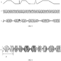
FIG. 4 , in the embodiment, the pattern of the basic waveform in the step 31 is a trapezoidal wave, and the waveform parameters are represented by a rising edge duration time t1, a high level duration time t2, a falling edge duration time t3 and a low level duration time t4. A variety of basic waveforms of different frequencies and types can be obtained according to the length of each duration time. - As shown in
FIG. 5 , in the embodiment, the settings of the first-order wave group 3 in the steps 32 and 33 can be represented as: n1 (First Basic Waveform) + n2 (Second Basic Waveform) + n3 (Third Basic Waveform) + n4 (Fourth Basic Waveform) + n5 (Fifth Basic Waveform), meaning that thebasic wave group 1 is combined by n1 first basic waveforms, n2 second basic waveforms, n3 third basic waveforms, n4 fourth basic waveforms and n5 fifth basic waveforms, wherein n1, n2, n3, n4 and n5 are integers.FIG. 5 shows a cycle of the basic waveform. The duration time of the basic waveform is determined by the frequency and number of the basic waveforms. The frequency of thecarrier wave 2 is set in the step 34, and thecarrier wave 2 is modulated by thebasic wave group 1 to obtain a first-order wave group 3 in the step 35. - As shown in
FIG. 6 , in the embodiment, the settings of the second-order wave group 4 in the steps 36 and 37 can be represented as: m1 (First First-order Wave Group) + m2 (Second First-order Wave Group) + m3 (Third First-order Wave Group) + m4 (Fourth First-order Wave Group) + m5 (Fifth First-order Wave Group), meaning that the second-order wave group is combined by n1 first first-order wave groups, n2 second first-order wave groups, n3 third first-order wave groups, n4 fourth first-order wave groups and n5 fifth first-order wave groups, wherein n1, n2, n3, n4 and n5 are integers.FIG. 6 shows a cycle of the first-order wave group. - In the embodiment, there is a set of parameters of the wave group for a good analgesic effect as follows. For the basic waveform, the rising edge duration time t1 and the falling edge duration time t3 are zero, and the high level duration time t2 and the low level duration time t4 are half of the period respective. There are eight basic waveforms of different frequencies including 2 Hz, 5 Hz, 10 Hz, 20 Hz, 25 Hz, 50Hz, 75 Hz and 100 Hz, and the corresponding periods are 500ms, 200ms, 100ms, 50ms, 40ms, 20ms, 13.3ms and 10ms respectively. The analgesic wave groups output to the hands and waist of the parturient are implemented by different first-order wave groups, but in order to make the hands and waist have the same feeling, the carrier frequencies output to the hands and waist at the same time are the same.
- First basic wave group: total duration time: 15 seconds, and carrier frequency: 1 KHz.
- Waist: 10 (2Hz) + 192 (5 Hz) + 128 (50 Hz) + 64 (25 Hz) + 255 (100 Hz)
- Hand: 10 (2Hz) + 192 (75 Hz) + 128 (50 Hz) + 64 (25 Hz) + 255 (100 Hz)
- Second basic wave group: total duration time: 11.6 seconds, and carrier frequency: 2.5 KHz.
- Waist: 15 (5Hz) + 80 (5 Hz) + 10 (2 Hz) + 80 (100 Hz) + 20 (10 Hz)
- Hand: 15 (2Hz) + 40 (50 Hz) + 10 (2 Hz) + 40 (50 Hz) + 20 (10 Hz)
- Third basic wave group: total duration time: 21 seconds, and carrier frequency: 2.5 KHz.
- Waist: 20 (2Hz) + 300 (75 Hz) + 99 (25 Hz) + 200 (100 Hz) + 50 (50 Hz)
- Hand: 20 (2Hz) + 200 (50 Hz) + 990 (25 Hz) + 50 (100 Hz) + 125 (50 Hz)
- Fourth basic wave group: total duration time: 9.5 seconds, and carrier frequency: 2.5 KHz.
- Waist: 10 (2Hz) + 50 (20 Hz) + 198 (100 Hz)
- Hand: 10 (2Hz) + 50 (20 Hz) + 99 (50 Hz)
- Fifth basic wave group: total duration time: 28 seconds, and carrier frequency: 1 KHz.
- Waist: 30 (2Hz) + 300 (75 Hz) + 99 (25 Hz) + 300 (100 Hz) + 90 (50 Hz)
- Hand: 30 (2Hz) + 300 (75 Hz) + 990 (25 Hz) + 80 (100 Hz) + 200 (50 Hz)
- Sixth basic wave group: total duration time: 9.5 seconds, and carrier frequency: 1 KHz.
- Waist: 10 (2Hz) + 50 (20 Hz) + 198 (100 Hz)
- Hand: 10 (2Hz) + 50 (20 Hz) + 99 (50 Hz)
- By modulating corresponding carrier waves with the above first to sixth basic wave groups, two better electrical-stimulation wave groups can be obtained as below.
- First second-order wave group: 42 (Third first-order wave group) + 38 (Fourth first-order wave group) + 56 (Fifth first-order wave group) + 24 (Second first-order wave group) + 45 (First first-order wave group)
- Second second-order wave group: 42 (Third first-order wave group) + 38 (Sixth first-order wave group) + 24 (Second first-order wave group) + 56 (Fifth first-order wave group) + 38 (Fourth first-order wave group) + 45 (First first-order wave group)
- At least two of the electrical-stimulation wave groups of two types are stored according to the implement parameters in the steps 31∼37, in the electrical-stimulation wave group generator in advance, and the childbirth pain-relief station conducts a comprehensive analysis according to the pressure value of uterine contraction from the maternal-fetal monitoring module and hand-grip pressure value from the hand-grip pressure transducer to calculate a output type, frequency and amplitude the electrical-stimulation wave group.
- In the embodiment, as shown in
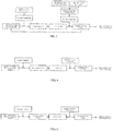
FIG. 7 , the electrical-stimulation wave group generator includes a waveform sampled data storage unit, a frequency storage unit, an amplitude storage unit, a data reading unit, a D/A converter and an amplifying-driving circuit. The real-time frequency and amplitude of the electrical-stimulation wave group are calculated based on the output type and amplitude of the electrical-stimulation wave group calculated buy the childbirth pain-relief station as follows. (1) The real-time frequency of the electrical-stimulation wave group is calculated based on the implement parameters of the electrical-stimulation wave group corresponding to the output type of the electrical-stimulation wave group calculated by the childbirth pain-relief station, that is, the real-time frequency of the electrical-stimulation wave group is equal to the real-time frequency of the carrier signal stored in the step 34 in advance; and (2) the real-time amplitude of the electrical-stimulation wave group is calculated based on the implement parameters of the electrical-stimulation wave group corresponding to the output type of the electrical-stimulation wave group calculated by the childbirth pain-relief station, and based on the output amplitude of the amplitude calculated by the childbirth pain-relief station, that is, the real-time amplitude of the electrical-stimulation wave group is calculated based on the pattern parameters stored in the step 31, the sequence of combination stored in the step 32 and the duration time stored in the step 33 in advance, and the real-time amplitude of the electrical-stimulation wave group is equal to the real-time amplitude of the basic wave group times the amplitude of the electrical-stimulation wave group stored in advance. The waveform sampled data storage unit is configured to store sampled data of a cycle of carrier signal, the frequency storage unit is configured to store a real-time frequency of the electrical-stimulation wave group, the amplitude storage unit is configured to store a real-time amplitude of the electrical-stimulation wave group, the data reading unit data reading unit is configured to circularly read the waveform sampled data storage unit at the frequency stored in the frequency storage unit, and circularly output waveform sampled data in sequence, the D/A converter is configured to convert the waveform sampled data to analog signal, and the amplifying-driving circuit is configured to adjust the electrical-stimulation wave group to be output according to the amplitude stored in the amplitude storage unit. - The example is similar to Example One, excepting that the sampled data of the electrical-stimulation wave group itself is stored in the electrical-stimulation wave group generator in advance, and it is selected for output according to actual need, as follows. At least two of the electrical-stimulation wave groups of two types are stored in the electrical-stimulation wave group generator in advance, and the childbirth pain-relief station conducts a comprehensive analysis according to the pressure value of uterine contraction from the maternal-fetal monitoring module and hand-grip pressure value from the hand-grip pressure transducer to calculate the output type, frequency and amplitude the electrical-stimulation wave group.
- As shown in
FIG. 8 , the electrical-stimulation wave group generator includes a wave group sampled database, a microcomputer system, D/A converter and an amplifying-driving circuit connected in sequence. The wave group sampled database is provided in a storage medium selected from the group consisting of magnetic disk, optical disc, USB flash disk, CF card and SD card, and configured to store the sampled data of at least two of the electrical-stimulation wave groups, the microcomputer system is configured to sequentially read wave group sampled data of a corresponding type from the wave group sampled database at a sampling frequency of the electrical-stimulation wave group, according to the output type of the electrical-stimulation wave group calculated by the childbirth pain-relief station, the D/A converter is configured to convert the wave group sampled data to an electrical-stimulation wave group, and the amplifying-driving circuit is configured to adjust the electrical-stimulation wave group to be output according to the output amplitude of the electrical-stimulation wave group calculated by the childbirth pain-relief station. - The example is similar to Example One, excepting that excepting that the sampled data of the electrical-stimulation wave group itself is stored in the electrical-stimulation wave group generator in advance, and it is selected for output according to actual need, as follows. At least two of the electrical-stimulation wave groups of two types are stored in the electrical-stimulation wave group generator in advance, and the childbirth pain-relief station conducts a comprehensive analysis according to the pressure value of uterine contraction from the maternal-fetal monitoring module and hand-grip pressure value from the hand-grip pressure transducer to calculate the output type, frequency and amplitude the electrical-stimulation wave group.
- As shown in
FIG. 9 , the electrical-stimulation wave group generator includes a wave group sampled data memory, an automatic scanning circuit, D/A converter and an amplifying-driving circuit connected in sequence. The wave group sampled data memory is selected from the group consisting of ROM, PROM, PROM, E2PROM and flash memory, and is configured to store the sampled data of at least two of the electrical-stimulation wave groups, the automatic scanning circuit is configured to generate address information with a digital logic circuit, and scan a waveform data storage unit a corresponding type at a sampling frequency of the electrical-stimulation wave group to make the memory output wave group sampled data in turn, according to the output type of the electrical-stimulation wave group calculated by the childbirth pain-relief station, the D/A converter is configured to convert the wave group sampled data to an electrical-stimulation wave group, and the amplifying-driving circuit is configured to adjust the electrical-stimulation wave group to be output according to the output amplitude of the electrical-stimulation wave group calculated by the childbirth pain-relief station. - In other embodiments, the implement parameters of the electrical-stimulation wave group or the type, frequency and amplitude of the electrical-stimulation wave group can also be manually set, and the device according to Example One to Three outputs the electrical-stimulation wave group.
- The above embodiments are chosen and described in order to explain the principles of the disclosure and their practical application so as to activate others skilled in the art to utilize the disclosure. Alternative embodiments will become apparent to those skilled in the art to which the present disclosure pertains without departing from its scope. Accordingly, the scope of the present disclosure is defined by the appended claims rather than the foregoing description and the exemplary embodiments described therein.
Claims (7)
- A bio-feedback type device for physical pain relief at childbirth, comprising a childbirth pain-relief station and an electrical-stimulation wave group output module, wherein the apparatus further comprising a maternal-fetal monitoring module, a hand-grip pressure transducer, and an electrical-stimulation wave group generator; the maternal-fetal monitoring module, the hand-grip pressure transducer and the electrical-stimulation wave group generator are coupled respectively to the childbirth pain-relief station, and the electrical-stimulation wave group generator is coupled to the electrical-stimulation wave group output module;
the maternal-fetal monitoring module is configured to detect a maternal-fetal physical signal and transmit the detected maternal-fetal physical signal to the childbirth pain-relief station;
the hand-grip pressure transducer is configured to convert a degree of a pain born by a parturient to a hand-grip pressure value and transmit the converted hand-grip pressure value to the childbirth pain-relief station;
the childbirth pain-relief station is configured to regulate an output parameter of electrical-stimulation wave group by analyzing a pressure value of uterine contraction in the maternal-fetal physical signal and the hand-grip pressure value from the hand-grip pressure transducer, and calculating the output parameter of electrical-stimulation wave group according to the analyzing; the output parameter of electrical-stimulation wave group including type, frequency and amplitude of the electrical-stimulation wave group;
the electrical-stimulation wave group generator is configured to generate a corresponding electrical-stimulation wave group according to the output parameter of electrical-stimulation wave group regulated by the childbirth pain-relief station, and the electrical-stimulation wave group output module is configured to output the electrical-stimulation wave group to the parturient's body,
wherein regulating the output parameter of electrical-stimulation wave group by the childbirth pain-relief station comprises:step 1, detecting a maximum hand-grip pressure value of the parturient, Fmax, by the hand-grip pressure transducer;step 2, detecting a real time pressure value of uterine contraction, TOCO, by the maternal-fetal monitoring module;step 3, detecting a real time hand-grip pressure value of the parturient, F, by the hand-grip pressure transducer; andstep 4, originally calculating a type XTOCO and an amplitude ATOCO of the electrical-stimulation wave group according to the TOCO detected in the step 2, andwhen TOCO>TOCOthreshold, the type XTOCO of the electrical-stimulation wave group is set to an analgesic wave group, and when TOCO<TOCOthreshold, the type XTOCO of the electrical-stimulation wave group is a massage wave group, wherein, the TOCOthreshold is a pain threshold of uterine contraction pressure, andthe amplitude ATOCO of the electrical-stimulation wave group is ATOCO=KTOCO *TOCO +Adefault, wherein Adefault is a minimum amplitude Amin, and KTOCO is a proportional coefficient of the amplitude ATOCO of the electrical-stimulation wave group and the real time pressure value of uterine contraction TOCO;step 5, further calculating a type XF and an amplitude AF of the electrical-stimulation wave group according to the real time hand-grip pressure value F detected in the step 3, andwhen F< Fkthreshold*Fmax, XF is set to XTOCO, and the amplitude AF of the electrical-stimulation wave group is AF=ATOCO + KF *F+Adefault, wherein Fkthreshold is a pain threshold of the hand-grip pressure value and meets Fkthreshold>0, and KF is a proportional coefficient of the amplitude AF of the electrical-stimulation wave group and the hand-grip pressure value F; andwhen F> Fkthreshold*Fmax, XF is set to an analgesic wave group, wherein if the XTOCO is a massage wave group, the amplitude AF of the electrical-stimulation wave group is AF= KF *F+Adefault, and if the XTOCO is a an analgesic wave group, the amplitude AF of the electrical-stimulation wave group is AF=ATOCO + KF *F+Adefault;step 6, determining a final output type X and amplitude A of the electrical-stimulation wave group according to two calculations in the step 4 and the step 5, and synthesizing a final electrical-stimulation wave group according to the final output type X and an amplitude A; andonly when both of the XTOCO and the XF are massage wave groups, the type X of the final electrical-stimulation wave group is set to a massage wave group; in other cases, the type X is set to an analgesic wave group; and the final output amplitude A is set to A=AF, wherein A is less than an upper safety limit of the amplitude Amax set by a system. - The bio-feedback type device for physical pain relief at childbirth of claim 1, wherein the synthesizing in the step 6 comprising:step 31, setting pattern parameters of each combined basic waveform of a low frequency modulation wave group;step 32, setting a sequence of combination of each combined basic waveform of the low frequency modulation wave group;step 33, setting a duration time of each combined basic waveform of the low frequency modulation wave group, combining the basic waveforms into a basic wave group, i.e., a low frequency modulation signal;step 34, setting a corresponding carrier frequency, to obtain a carrier signal;step 35, modulating the carrier signal in the step 34 with the basic wave group in the step 33 to obtain a first-order wave group;step 36, repeating steps 31∼35, to obtain a plurality of first-order wave groups of different characteristics; andstep 37, selecting three to six first-order wave groups obtained in the step 35, and setting a sequence of combination and a duration time to obtain a second-order wave group as an electrical-stimulation wave group.
- The bio-feedback type device for physical pain relief at childbirth of any one of claims 1-2, wherein the electrical-stimulation wave group generator comprises a waveform sampled data storage unit, a frequency storage unit, an amplitude storage unit, a data reading unit, a D/A converter and an amplifying-driving circuit,
wherein the waveform sampled data storage unit is configured to store sampled data of a cycle of carrier signal, the frequency storage unit is configured to store a real-time frequency of the electrical-stimulation wave group, the amplitude storage unit is configured to store a real-time amplitude of the electrical-stimulation wave group, the data reading unit data reading unit is configured to circularly read the waveform sampled data storage unit at the frequency stored in the frequency storage unit, and circularly output waveform sampled data in sequence, the D/A converter is configured to convert the waveform sampled data to analog signal, and the amplifying-driving circuit is configured to adjust the electrical-stimulation wave group to be output according to the amplitude stored in the amplitude storage unit. - The bio-feedback type device for physical pain relief at childbirth of any one of claims 1-2, wherein the electrical-stimulation wave group generator comprises a wave group sampled database, a microcomputer system, a D/A converter and an amplifying-driving circuit connected in sequence,
wherein the wave group sampled database is provided in a storage medium, and configured to store the sampled data of at least two of the electrical-stimulation wave groups; the microcomputer system is configured to sequentially read wave group sampled data of a corresponding type from the wave group sampled database at a sampling frequency of the electrical-stimulation wave group, according to the output type of the electrical-stimulation wave group calculated by the childbirth pain-relief station; the D/A converter is configured to convert the wave group sampled data to an electrical-stimulation wave group; and the amplifying-driving circuit is configured to adjust the electrical-stimulation wave group to be output according to the output amplitude of the electrical-stimulation wave group calculated by the childbirth pain-relief station. - The bio-feedback type device for physical pain relief at childbirth of any one of claims 1-2, wherein the electrical-stimulation wave group generator comprises a wave group sampled data memory, an automatic scanning circuit, D/A converter and an amplifying-driving circuit connected in sequence,
wherein the wave group sampled data memory is configured to store the sampled data of at least two of the electrical-stimulation wave groups, the automatic scanning circuit is configured to generate address information with a digital logic circuit, and scan a waveform data storage unit a corresponding type at a sampling frequency of the electrical-stimulation wave group to cause the memory output wave group sampled data in turn, according to the output type of the electrical-stimulation wave group calculated by the childbirth pain-relief station; the D/A converter is configured to convert the wave group sampled data to an electrical-stimulation wave group, and the amplifying-driving circuit is configured to adjust the electrical-stimulation wave group to be output according to the output amplitude of the electrical-stimulation wave group calculated by the childbirth pain-relief station. - The bio-feedback type device for physical pain relief at childbirth of any one of claims 1-2, further comprises an input and display module configured to interact with an operator or a device, and coupled to the childbirth pain-relief station.
- The bio-feedback type device for physical pain relief at childbirth of claim 2,
wherein the basic waveform has a frequency range from 1 Hz to 150 Hz, and the waveform of the carrier wave is a sine wave or a square wave, with a frequency range from 150 Hz to 10 KHz.
Applications Claiming Priority (2)
| Application Number | Priority Date | Filing Date | Title |
|---|---|---|---|
| CN201210488575.3A CN102940934B (en) | 2012-11-26 | 2012-11-26 | Biological feedback type delivery physical analgesia device |
| PCT/CN2013/087035 WO2014079333A1 (en) | 2012-11-26 | 2013-11-13 | Bio-feedback type device for physical pain relief at childbirth |
Publications (3)
| Publication Number | Publication Date |
|---|---|
| EP2918309A1 EP2918309A1 (en) | 2015-09-16 |
| EP2918309A4 EP2918309A4 (en) | 2016-07-13 |
| EP2918309B1 true EP2918309B1 (en) | 2017-11-08 |
Family
ID=47723984
Family Applications (1)
| Application Number | Title | Priority Date | Filing Date |
|---|---|---|---|
| EP13857234.2A Not-in-force EP2918309B1 (en) | 2012-11-26 | 2013-11-13 | Bio-feedback type device for physical pain relief at childbirth |
Country Status (8)
| Country | Link |
|---|---|
| US (1) | US9333349B2 (en) |
| EP (1) | EP2918309B1 (en) |
| JP (1) | JP6109328B2 (en) |
| KR (1) | KR101695331B1 (en) |
| CN (1) | CN102940934B (en) |
| BR (1) | BR112015012056A2 (en) |
| RU (1) | RU2615868C2 (en) |
| WO (1) | WO2014079333A1 (en) |
Families Citing this family (25)
| Publication number | Priority date | Publication date | Assignee | Title |
|---|---|---|---|---|
| IN2014DN09885A (en) | 2012-05-31 | 2015-08-07 | Zoll Medical Corp | |
| US10328266B2 (en) * | 2012-05-31 | 2019-06-25 | Zoll Medical Corporation | External pacing device with discomfort management |
| US11097107B2 (en) | 2012-05-31 | 2021-08-24 | Zoll Medical Corporation | External pacing device with discomfort management |
| CN102940934B (en) * | 2012-11-26 | 2014-11-19 | 广州三瑞医疗器械有限公司 | Biological feedback type delivery physical analgesia device |
| CN103736205B (en) * | 2013-12-25 | 2015-09-23 | 广州三瑞医疗器械有限公司 | A distributed pain relief system and method thereof |
| CN104014076B (en) * | 2014-04-21 | 2016-02-24 | 广州三瑞医疗器械有限公司 | A kind of analgesia Wave form detector and method thereof |
| CN105288837A (en) * | 2014-07-28 | 2016-02-03 | 广州三瑞医疗器械有限公司 | System and method for detecting labor analgesia waveforms |
| CN104587600B (en) * | 2015-01-21 | 2018-11-16 | 广州三瑞医疗器械有限公司 | A kind of wearable inhibiting pain in parturition device |
| CN105528611A (en) * | 2015-06-24 | 2016-04-27 | 广州三瑞医疗器械有限公司 | Ache identification classifier training method and device |
| CN104984472B (en) * | 2015-06-24 | 2018-08-21 | 广州三瑞医疗器械有限公司 | Analgesia control method based on speech recognition and its device |
| JP2018082870A (en) * | 2016-11-24 | 2018-05-31 | 株式会社ジーウェーブ | Electric therapy device |
| KR102515448B1 (en) * | 2018-10-01 | 2023-03-30 | 료지 쿠와하타 | bio stimulator |
| CN109316662A (en) * | 2018-10-23 | 2019-02-12 | 合肥智法自然电子科技有限公司 | It is a kind of applied to analgesia and/or functional restoration electric stimulation pulse modulated signal |
| CN110432884B (en) * | 2019-07-08 | 2022-07-01 | 暨南大学 | Fetal condition evaluation method and system based on fetal heart rate deceleration area |
| CN110548207B (en) * | 2019-09-09 | 2021-04-09 | 吉林大学 | Anesthetic direct injection device for painless childbirth |
| US20210386362A1 (en) * | 2020-06-11 | 2021-12-16 | Fructus Design, LLC | Childbirth and labor monitoring method and system |
| CN112366006A (en) * | 2020-11-26 | 2021-02-12 | 上海市第一妇婴保健院 | Delivery pain assessment system and method |
| CN113057597B (en) * | 2021-03-25 | 2021-11-16 | 南通市第一人民医院 | Method and system for monitoring physiological state of puerpera in real time in production process |
| CN113855198B (en) * | 2021-10-13 | 2022-12-06 | 深圳众佐科技有限公司 | Image enhancement system for uterine contraction recognition |
| CN116785586A (en) * | 2022-03-17 | 2023-09-22 | 深圳市理邦精密仪器股份有限公司 | Method, device, equipment and medium for generating auxiliary electric stimulation for childbirth |
| CN115006678A (en) * | 2022-05-04 | 2022-09-06 | 复旦大学附属妇产科医院 | Delivery analgesia method and device with adjustable drug concentration |
| CN118178785B (en) * | 2024-04-18 | 2025-01-10 | 首都医科大学宣武医院 | Analgesic administration regulation and control system |
| CN119400370A (en) * | 2024-09-25 | 2025-02-07 | 维怡医疗科技有限公司 | A smart delivery method and system |
| CN119908735B (en) * | 2025-03-31 | 2026-04-21 | 西安交通大学医学院第一附属医院 | Exercise cortex excitability assessment method based on threshold tracking magnetic stimulation |
| CN121041548A (en) * | 2025-09-01 | 2025-12-02 | 首都医科大学附属北京口腔医院 | An Adaptive Control Method and System for Anesthesia Depth Based on Dynamic Temporal Model |
Family Cites Families (23)
| Publication number | Priority date | Publication date | Assignee | Title |
|---|---|---|---|---|
| US2989357A (en) * | 1956-04-13 | 1961-06-20 | Wallace A Verrett | Obstetric labor pain recorder |
| FR2420980A1 (en) * | 1978-03-30 | 1979-10-26 | Winkler U | AUTOMATICALLY CONTROLLED DEVICE SERVING TO AVOID CHILDBIRTH PAIN |
| JPS5855775B2 (en) * | 1979-09-01 | 1983-12-12 | 淳士 丸山 | Labor progress monitoring device |
| JPH0716271A (en) * | 1991-11-25 | 1995-01-20 | Yaeka Yoshino | Pain-alleviating obstetric aid instrument |
| CN2216389Y (en) * | 1992-12-02 | 1996-01-03 | 王立东 | Computer delivery analgesia, monitor |
| RU2092128C1 (en) * | 1995-06-28 | 1997-10-10 | Кубанский государственный аграрный университет | Method of electric stimulation of contraction of prelum abdominate and uterus muscles during pathological birth of animals and device intended for its realization |
| US5653739A (en) * | 1995-09-13 | 1997-08-05 | Empi, Inc. | Electronic pain feedback system and method |
| CN1148989A (en) * | 1995-10-25 | 1997-05-07 | 李晓森 | Computer apparatus for monitoring childbirth and analgesia |
| US6879858B1 (en) * | 1998-11-25 | 2005-04-12 | Reproductive Health Technologies, Inc. | Uterine contraction detection and initiation system and method |
| WO2000056401A1 (en) * | 1999-03-24 | 2000-09-28 | Milkhaus Foundation For Children | Apparatus and methods for reducing pain and/or retraining muscles |
| US7862521B1 (en) * | 2002-03-27 | 2011-01-04 | Parker-Hannifin Corporation | Uterine contraction sensing system and method |
| KR100630058B1 (en) * | 2004-06-01 | 2006-09-27 | 삼성전자주식회사 | Low frequency stimulation device provided in portable terminal and control method thereof |
| CN2737391Y (en) | 2004-09-29 | 2005-11-02 | 赵文忠 | Labor pains therapeutical instrument |
| CN2862954Y (en) * | 2005-12-01 | 2007-01-31 | 中国中医研究院骨伤科研究所 | Instrument for quantitatively measuring human body pressing pain |
| US7942818B2 (en) * | 2006-02-01 | 2011-05-17 | University Of Florida Research Foundation, Inc. | Obstetric analgesia system |
| CN101148989B (en) | 2007-08-09 | 2010-05-19 | 上海港机重工有限公司 | Tunnel shield digging machine local and remote monitoring method |
| AU2007359039B2 (en) * | 2007-09-18 | 2013-06-20 | Giuseppe Marineo | Apparatus and method for quick pain suppression |
| US8064991B2 (en) * | 2008-01-08 | 2011-11-22 | The General Electric Company | Method of fetal and maternal ECG identification across multiple EPOCHS |
| RU2405479C1 (en) * | 2009-07-02 | 2010-12-10 | Комитет здравоохранения администрации города Саратова Муниципальное учреждение здравоохранения "1-ая городская клиническая больница им. Ю.Я. Гордеева" | Method of diagnostics and treatment of postpartum uterine complications and device for method realisation |
| WO2011079966A1 (en) | 2009-12-28 | 2011-07-07 | Msys Ag | Device and method for detecting and measuring pain |
| CN202086950U (en) | 2011-06-08 | 2011-12-28 | 北京百福生医疗器械有限公司 | Labor analgesia apparatus for obstetrics and gynecology |
| CN102940934B (en) * | 2012-11-26 | 2014-11-19 | 广州三瑞医疗器械有限公司 | Biological feedback type delivery physical analgesia device |
| CN203280902U (en) * | 2012-11-26 | 2013-11-13 | 广州三瑞医疗器械有限公司 | Biological feedback type delivery physical analgesia device |
-
2012
- 2012-11-26 CN CN201210488575.3A patent/CN102940934B/en active Active
-
2013
- 2013-11-13 JP JP2015543278A patent/JP6109328B2/en not_active Expired - Fee Related
- 2013-11-13 EP EP13857234.2A patent/EP2918309B1/en not_active Not-in-force
- 2013-11-13 RU RU2015123568A patent/RU2615868C2/en active
- 2013-11-13 BR BR112015012056A patent/BR112015012056A2/en not_active Application Discontinuation
- 2013-11-13 WO PCT/CN2013/087035 patent/WO2014079333A1/en not_active Ceased
- 2013-11-13 KR KR1020157016748A patent/KR101695331B1/en not_active Expired - Fee Related
- 2013-11-13 US US14/646,956 patent/US9333349B2/en active Active
Non-Patent Citations (1)
| Title |
|---|
| None * |
Also Published As
| Publication number | Publication date |
|---|---|
| KR101695331B1 (en) | 2017-01-11 |
| JP2015535448A (en) | 2015-12-14 |
| US9333349B2 (en) | 2016-05-10 |
| RU2615868C2 (en) | 2017-04-11 |
| US20150335886A1 (en) | 2015-11-26 |
| CN102940934A (en) | 2013-02-27 |
| CN102940934B (en) | 2014-11-19 |
| RU2015123568A (en) | 2017-01-10 |
| BR112015012056A2 (en) | 2017-07-11 |
| JP6109328B2 (en) | 2017-04-05 |
| EP2918309A4 (en) | 2016-07-13 |
| KR20150090905A (en) | 2015-08-06 |
| EP2918309A1 (en) | 2015-09-16 |
| WO2014079333A1 (en) | 2014-05-30 |
Similar Documents
| Publication | Publication Date | Title |
|---|---|---|
| US9333349B2 (en) | Bio-feedback type device for physical pain relief at childbirth | |
| CN106999088A (en) | System and method for monitoring muscular recuperation | |
| CN111921089A (en) | An adaptive regulation of vagus nerve stimulation system based on HRV parameter feedback | |
| CN109475740B (en) | Electric stimulation therapeutic instrument | |
| CN115137941A (en) | Emergency awakening method and system based on fatigue recognition model and electrical stimulation | |
| CN112716453A (en) | Blood pressure and nerve signal collecting and analyzing method | |
| CN114904140A (en) | Physical therapy equipment, control method thereof and physical therapy system | |
| CN118304572A (en) | Integrated synchronous treatment system combining TMS and taVNS | |
| CN118161748A (en) | A neural electrical stimulation device and method for resisting fatigue and promoting alertness | |
| CN113952633A (en) | Noninvasive exercise fatigue intervention and evaluation method | |
| CN202843601U (en) | Mental and physical physiotherapy health care instrument | |
| KR101315128B1 (en) | Method evaluating human homeostasis by measuring multidimensional biomedical signals | |
| CN116831897A (en) | An adaptive intelligent massage and relaxation device | |
| US20240238612A1 (en) | Method for interval closed loop adaptive transcranial photobiomodulation | |
| CN203280902U (en) | Biological feedback type delivery physical analgesia device | |
| WO2019168500A1 (en) | Connection quality assessment for eeg electrode arrays | |
| WO2022146295A1 (en) | System and method where treatment of diseases and disorders is realized via stimulation of nerves | |
| CN202036686U (en) | Novel intelligent low-frequency therapeutic apparatus with testing function | |
| US11801384B2 (en) | Method for calibration of transcutaneous nerve stimulator | |
| CN115633969B (en) | Anesthesia pain nociception assessment method based on electroencephalogram signals and pulse signals | |
| Zhu et al. | Respiratory training biofeedback system | |
| CN118203765A (en) | An integrated intelligent treatment system combining TMS and taVNS | |
| CN120690371A (en) | A neurogenic bladder-anxiety coordinated regulation auxiliary system based on biofeedback | |
| AU2026203477A1 (en) | Method for interval closed-loop adaptive transcranial photobiomodulation | |
| TWM670996U (en) | Biophysical signal detection apparatus |
Legal Events
| Date | Code | Title | Description |
|---|---|---|---|
| PUAI | Public reference made under article 153(3) epc to a published international application that has entered the european phase |
Free format text: ORIGINAL CODE: 0009012 |
|
| 17P | Request for examination filed |
Effective date: 20150610 |
|
| AK | Designated contracting states |
Kind code of ref document: A1 Designated state(s): AL AT BE BG CH CY CZ DE DK EE ES FI FR GB GR HR HU IE IS IT LI LT LU LV MC MK MT NL NO PL PT RO RS SE SI SK SM TR |
|
| AX | Request for extension of the european patent |
Extension state: BA ME |
|
| DAX | Request for extension of the european patent (deleted) | ||
| RA4 | Supplementary search report drawn up and despatched (corrected) |
Effective date: 20160609 |
|
| RIC1 | Information provided on ipc code assigned before grant |
Ipc: A61N 1/36 20060101AFI20160603BHEP |
|
| GRAP | Despatch of communication of intention to grant a patent |
Free format text: ORIGINAL CODE: EPIDOSNIGR1 |
|
| STAA | Information on the status of an ep patent application or granted ep patent |
Free format text: STATUS: GRANT OF PATENT IS INTENDED |
|
| INTG | Intention to grant announced |
Effective date: 20170621 |
|
| GRAS | Grant fee paid |
Free format text: ORIGINAL CODE: EPIDOSNIGR3 |
|
| GRAA | (expected) grant |
Free format text: ORIGINAL CODE: 0009210 |
|
| STAA | Information on the status of an ep patent application or granted ep patent |
Free format text: STATUS: THE PATENT HAS BEEN GRANTED |
|
| AK | Designated contracting states |
Kind code of ref document: B1 Designated state(s): AL AT BE BG CH CY CZ DE DK EE ES FI FR GB GR HR HU IE IS IT LI LT LU LV MC MK MT NL NO PL PT RO RS SE SI SK SM TR |
|
| REG | Reference to a national code |
Ref country code: GB Ref legal event code: FG4D |
|
| REG | Reference to a national code |
Ref country code: CH Ref legal event code: EP Ref country code: AT Ref legal event code: REF Ref document number: 943575 Country of ref document: AT Kind code of ref document: T Effective date: 20171115 |
|
| REG | Reference to a national code |
Ref country code: FR Ref legal event code: PLFP Year of fee payment: 5 Ref country code: IE Ref legal event code: FG4D |
|
| REG | Reference to a national code |
Ref country code: DE Ref legal event code: R096 Ref document number: 602013029290 Country of ref document: DE |
|
| REG | Reference to a national code |
Ref country code: NL Ref legal event code: MP Effective date: 20171108 |
|
| REG | Reference to a national code |
Ref country code: LT Ref legal event code: MG4D |
|
| REG | Reference to a national code |
Ref country code: AT Ref legal event code: MK05 Ref document number: 943575 Country of ref document: AT Kind code of ref document: T Effective date: 20171108 |
|
| PG25 | Lapsed in a contracting state [announced via postgrant information from national office to epo] |
Ref country code: FI Free format text: LAPSE BECAUSE OF FAILURE TO SUBMIT A TRANSLATION OF THE DESCRIPTION OR TO PAY THE FEE WITHIN THE PRESCRIBED TIME-LIMIT Effective date: 20171108 Ref country code: ES Free format text: LAPSE BECAUSE OF FAILURE TO SUBMIT A TRANSLATION OF THE DESCRIPTION OR TO PAY THE FEE WITHIN THE PRESCRIBED TIME-LIMIT Effective date: 20171108 Ref country code: LT Free format text: LAPSE BECAUSE OF FAILURE TO SUBMIT A TRANSLATION OF THE DESCRIPTION OR TO PAY THE FEE WITHIN THE PRESCRIBED TIME-LIMIT Effective date: 20171108 Ref country code: NL Free format text: LAPSE BECAUSE OF FAILURE TO SUBMIT A TRANSLATION OF THE DESCRIPTION OR TO PAY THE FEE WITHIN THE PRESCRIBED TIME-LIMIT Effective date: 20171108 Ref country code: SE Free format text: LAPSE BECAUSE OF FAILURE TO SUBMIT A TRANSLATION OF THE DESCRIPTION OR TO PAY THE FEE WITHIN THE PRESCRIBED TIME-LIMIT Effective date: 20171108 Ref country code: NO Free format text: LAPSE BECAUSE OF FAILURE TO SUBMIT A TRANSLATION OF THE DESCRIPTION OR TO PAY THE FEE WITHIN THE PRESCRIBED TIME-LIMIT Effective date: 20180208 |
|
| PG25 | Lapsed in a contracting state [announced via postgrant information from national office to epo] |
Ref country code: GR Free format text: LAPSE BECAUSE OF FAILURE TO SUBMIT A TRANSLATION OF THE DESCRIPTION OR TO PAY THE FEE WITHIN THE PRESCRIBED TIME-LIMIT Effective date: 20180209 Ref country code: LV Free format text: LAPSE BECAUSE OF FAILURE TO SUBMIT A TRANSLATION OF THE DESCRIPTION OR TO PAY THE FEE WITHIN THE PRESCRIBED TIME-LIMIT Effective date: 20171108 Ref country code: IS Free format text: LAPSE BECAUSE OF FAILURE TO SUBMIT A TRANSLATION OF THE DESCRIPTION OR TO PAY THE FEE WITHIN THE PRESCRIBED TIME-LIMIT Effective date: 20180308 Ref country code: BG Free format text: LAPSE BECAUSE OF FAILURE TO SUBMIT A TRANSLATION OF THE DESCRIPTION OR TO PAY THE FEE WITHIN THE PRESCRIBED TIME-LIMIT Effective date: 20180208 Ref country code: RS Free format text: LAPSE BECAUSE OF FAILURE TO SUBMIT A TRANSLATION OF THE DESCRIPTION OR TO PAY THE FEE WITHIN THE PRESCRIBED TIME-LIMIT Effective date: 20171108 Ref country code: HR Free format text: LAPSE BECAUSE OF FAILURE TO SUBMIT A TRANSLATION OF THE DESCRIPTION OR TO PAY THE FEE WITHIN THE PRESCRIBED TIME-LIMIT Effective date: 20171108 Ref country code: AT Free format text: LAPSE BECAUSE OF FAILURE TO SUBMIT A TRANSLATION OF THE DESCRIPTION OR TO PAY THE FEE WITHIN THE PRESCRIBED TIME-LIMIT Effective date: 20171108 |
|
| PG25 | Lapsed in a contracting state [announced via postgrant information from national office to epo] |
Ref country code: CY Free format text: LAPSE BECAUSE OF FAILURE TO SUBMIT A TRANSLATION OF THE DESCRIPTION OR TO PAY THE FEE WITHIN THE PRESCRIBED TIME-LIMIT Effective date: 20171108 Ref country code: DK Free format text: LAPSE BECAUSE OF FAILURE TO SUBMIT A TRANSLATION OF THE DESCRIPTION OR TO PAY THE FEE WITHIN THE PRESCRIBED TIME-LIMIT Effective date: 20171108 Ref country code: EE Free format text: LAPSE BECAUSE OF FAILURE TO SUBMIT A TRANSLATION OF THE DESCRIPTION OR TO PAY THE FEE WITHIN THE PRESCRIBED TIME-LIMIT Effective date: 20171108 Ref country code: LI Free format text: LAPSE BECAUSE OF NON-PAYMENT OF DUE FEES Effective date: 20171130 Ref country code: CZ Free format text: LAPSE BECAUSE OF FAILURE TO SUBMIT A TRANSLATION OF THE DESCRIPTION OR TO PAY THE FEE WITHIN THE PRESCRIBED TIME-LIMIT Effective date: 20171108 Ref country code: SK Free format text: LAPSE BECAUSE OF FAILURE TO SUBMIT A TRANSLATION OF THE DESCRIPTION OR TO PAY THE FEE WITHIN THE PRESCRIBED TIME-LIMIT Effective date: 20171108 Ref country code: CH Free format text: LAPSE BECAUSE OF NON-PAYMENT OF DUE FEES Effective date: 20171130 |
|
| REG | Reference to a national code |
Ref country code: DE Ref legal event code: R097 Ref document number: 602013029290 Country of ref document: DE |
|
| PG25 | Lapsed in a contracting state [announced via postgrant information from national office to epo] |
Ref country code: PL Free format text: LAPSE BECAUSE OF FAILURE TO SUBMIT A TRANSLATION OF THE DESCRIPTION OR TO PAY THE FEE WITHIN THE PRESCRIBED TIME-LIMIT Effective date: 20171108 Ref country code: LU Free format text: LAPSE BECAUSE OF NON-PAYMENT OF DUE FEES Effective date: 20171113 Ref country code: SM Free format text: LAPSE BECAUSE OF FAILURE TO SUBMIT A TRANSLATION OF THE DESCRIPTION OR TO PAY THE FEE WITHIN THE PRESCRIBED TIME-LIMIT Effective date: 20171108 Ref country code: RO Free format text: LAPSE BECAUSE OF FAILURE TO SUBMIT A TRANSLATION OF THE DESCRIPTION OR TO PAY THE FEE WITHIN THE PRESCRIBED TIME-LIMIT Effective date: 20171108 |
|
| REG | Reference to a national code |
Ref country code: BE Ref legal event code: MM Effective date: 20171130 |
|
| REG | Reference to a national code |
Ref country code: IE Ref legal event code: MM4A |
|
| PLBE | No opposition filed within time limit |
Free format text: ORIGINAL CODE: 0009261 |
|
| STAA | Information on the status of an ep patent application or granted ep patent |
Free format text: STATUS: NO OPPOSITION FILED WITHIN TIME LIMIT |
|
| PG25 | Lapsed in a contracting state [announced via postgrant information from national office to epo] |
Ref country code: MT Free format text: LAPSE BECAUSE OF NON-PAYMENT OF DUE FEES Effective date: 20171113 |
|
| 26N | No opposition filed |
Effective date: 20180809 |
|
| PG25 | Lapsed in a contracting state [announced via postgrant information from national office to epo] |
Ref country code: IE Free format text: LAPSE BECAUSE OF NON-PAYMENT OF DUE FEES Effective date: 20171113 |
|
| PG25 | Lapsed in a contracting state [announced via postgrant information from national office to epo] |
Ref country code: BE Free format text: LAPSE BECAUSE OF NON-PAYMENT OF DUE FEES Effective date: 20171130 Ref country code: SI Free format text: LAPSE BECAUSE OF FAILURE TO SUBMIT A TRANSLATION OF THE DESCRIPTION OR TO PAY THE FEE WITHIN THE PRESCRIBED TIME-LIMIT Effective date: 20171108 |
|
| PG25 | Lapsed in a contracting state [announced via postgrant information from national office to epo] |
Ref country code: HU Free format text: LAPSE BECAUSE OF FAILURE TO SUBMIT A TRANSLATION OF THE DESCRIPTION OR TO PAY THE FEE WITHIN THE PRESCRIBED TIME-LIMIT; INVALID AB INITIO Effective date: 20131113 Ref country code: MC Free format text: LAPSE BECAUSE OF FAILURE TO SUBMIT A TRANSLATION OF THE DESCRIPTION OR TO PAY THE FEE WITHIN THE PRESCRIBED TIME-LIMIT Effective date: 20171108 |
|
| PG25 | Lapsed in a contracting state [announced via postgrant information from national office to epo] |
Ref country code: MK Free format text: LAPSE BECAUSE OF FAILURE TO SUBMIT A TRANSLATION OF THE DESCRIPTION OR TO PAY THE FEE WITHIN THE PRESCRIBED TIME-LIMIT Effective date: 20171108 |
|
| PG25 | Lapsed in a contracting state [announced via postgrant information from national office to epo] |
Ref country code: TR Free format text: LAPSE BECAUSE OF FAILURE TO SUBMIT A TRANSLATION OF THE DESCRIPTION OR TO PAY THE FEE WITHIN THE PRESCRIBED TIME-LIMIT Effective date: 20171108 |
|
| PG25 | Lapsed in a contracting state [announced via postgrant information from national office to epo] |
Ref country code: PT Free format text: LAPSE BECAUSE OF FAILURE TO SUBMIT A TRANSLATION OF THE DESCRIPTION OR TO PAY THE FEE WITHIN THE PRESCRIBED TIME-LIMIT Effective date: 20171108 |
|
| PG25 | Lapsed in a contracting state [announced via postgrant information from national office to epo] |
Ref country code: AL Free format text: LAPSE BECAUSE OF FAILURE TO SUBMIT A TRANSLATION OF THE DESCRIPTION OR TO PAY THE FEE WITHIN THE PRESCRIBED TIME-LIMIT Effective date: 20171108 |
|
| PGFP | Annual fee paid to national office [announced via postgrant information from national office to epo] |
Ref country code: GB Payment date: 20231123 Year of fee payment: 11 |
|
| PGFP | Annual fee paid to national office [announced via postgrant information from national office to epo] |
Ref country code: IT Payment date: 20231124 Year of fee payment: 11 Ref country code: FR Payment date: 20231120 Year of fee payment: 11 Ref country code: DE Payment date: 20231121 Year of fee payment: 11 |
|
| REG | Reference to a national code |
Ref country code: DE Ref legal event code: R119 Ref document number: 602013029290 Country of ref document: DE |
|
| GBPC | Gb: european patent ceased through non-payment of renewal fee |
Effective date: 20241113 |
|
| PG25 | Lapsed in a contracting state [announced via postgrant information from national office to epo] |
Ref country code: DE Free format text: LAPSE BECAUSE OF NON-PAYMENT OF DUE FEES Effective date: 20250603 |
|
| PG25 | Lapsed in a contracting state [announced via postgrant information from national office to epo] |
Ref country code: IT Free format text: LAPSE BECAUSE OF NON-PAYMENT OF DUE FEES Effective date: 20241113 |
|
| PG25 | Lapsed in a contracting state [announced via postgrant information from national office to epo] |
Ref country code: GB Free format text: LAPSE BECAUSE OF NON-PAYMENT OF DUE FEES Effective date: 20241113 |
|
| PG25 | Lapsed in a contracting state [announced via postgrant information from national office to epo] |
Ref country code: FR Free format text: LAPSE BECAUSE OF NON-PAYMENT OF DUE FEES Effective date: 20241130 |