EP2918306A1 - Guide wire - Google Patents
Guide wire Download PDFInfo
- Publication number
- EP2918306A1 EP2918306A1 EP15156272.5A EP15156272A EP2918306A1 EP 2918306 A1 EP2918306 A1 EP 2918306A1 EP 15156272 A EP15156272 A EP 15156272A EP 2918306 A1 EP2918306 A1 EP 2918306A1
- Authority
- EP
- European Patent Office
- Prior art keywords
- guide wire
- winding
- curved section
- coil
- coil body
- Prior art date
- Legal status (The legal status is an assumption and is not a legal conclusion. Google has not performed a legal analysis and makes no representation as to the accuracy of the status listed.)
- Granted
Links
Images


Classifications
-
- A—HUMAN NECESSITIES
- A61—MEDICAL OR VETERINARY SCIENCE; HYGIENE
- A61M—DEVICES FOR INTRODUCING MEDIA INTO, OR ONTO, THE BODY; DEVICES FOR TRANSDUCING BODY MEDIA OR FOR TAKING MEDIA FROM THE BODY; DEVICES FOR PRODUCING OR ENDING SLEEP OR STUPOR
- A61M25/00—Catheters; Hollow probes
- A61M25/01—Introducing, guiding, advancing, emplacing or holding catheters
- A61M25/09—Guide wires
-
- A—HUMAN NECESSITIES
- A61—MEDICAL OR VETERINARY SCIENCE; HYGIENE
- A61M—DEVICES FOR INTRODUCING MEDIA INTO, OR ONTO, THE BODY; DEVICES FOR TRANSDUCING BODY MEDIA OR FOR TAKING MEDIA FROM THE BODY; DEVICES FOR PRODUCING OR ENDING SLEEP OR STUPOR
- A61M25/00—Catheters; Hollow probes
- A61M25/01—Introducing, guiding, advancing, emplacing or holding catheters
- A61M25/09—Guide wires
- A61M2025/09058—Basic structures of guide wires
- A61M2025/09083—Basic structures of guide wires having a coil around a core
-
- A—HUMAN NECESSITIES
- A61—MEDICAL OR VETERINARY SCIENCE; HYGIENE
- A61M—DEVICES FOR INTRODUCING MEDIA INTO, OR ONTO, THE BODY; DEVICES FOR TRANSDUCING BODY MEDIA OR FOR TAKING MEDIA FROM THE BODY; DEVICES FOR PRODUCING OR ENDING SLEEP OR STUPOR
- A61M25/00—Catheters; Hollow probes
- A61M25/01—Introducing, guiding, advancing, emplacing or holding catheters
- A61M25/09—Guide wires
- A61M2025/09058—Basic structures of guide wires
- A61M2025/09083—Basic structures of guide wires having a coil around a core
- A61M2025/09091—Basic structures of guide wires having a coil around a core where a sheath surrounds the coil at the distal part
-
- A—HUMAN NECESSITIES
- A61—MEDICAL OR VETERINARY SCIENCE; HYGIENE
- A61M—DEVICES FOR INTRODUCING MEDIA INTO, OR ONTO, THE BODY; DEVICES FOR TRANSDUCING BODY MEDIA OR FOR TAKING MEDIA FROM THE BODY; DEVICES FOR PRODUCING OR ENDING SLEEP OR STUPOR
- A61M25/00—Catheters; Hollow probes
- A61M25/01—Introducing, guiding, advancing, emplacing or holding catheters
- A61M25/09—Guide wires
- A61M2025/09108—Methods for making a guide wire
-
- A—HUMAN NECESSITIES
- A61—MEDICAL OR VETERINARY SCIENCE; HYGIENE
- A61M—DEVICES FOR INTRODUCING MEDIA INTO, OR ONTO, THE BODY; DEVICES FOR TRANSDUCING BODY MEDIA OR FOR TAKING MEDIA FROM THE BODY; DEVICES FOR PRODUCING OR ENDING SLEEP OR STUPOR
- A61M25/00—Catheters; Hollow probes
- A61M25/01—Introducing, guiding, advancing, emplacing or holding catheters
- A61M25/09—Guide wires
- A61M2025/09175—Guide wires having specific characteristics at the distal tip
-
- A—HUMAN NECESSITIES
- A61—MEDICAL OR VETERINARY SCIENCE; HYGIENE
- A61M—DEVICES FOR INTRODUCING MEDIA INTO, OR ONTO, THE BODY; DEVICES FOR TRANSDUCING BODY MEDIA OR FOR TAKING MEDIA FROM THE BODY; DEVICES FOR PRODUCING OR ENDING SLEEP OR STUPOR
- A61M25/00—Catheters; Hollow probes
- A61M25/01—Introducing, guiding, advancing, emplacing or holding catheters
- A61M25/09—Guide wires
- A61M2025/09191—Guide wires made of twisted wires
Definitions
- the present invention relates to a guide wire used as a medical device inserted in a body cavity for treatment or examination.
- a tubular organ such as a blood vessel, a gastrointestinal tract, and a urinary duct, or a body tissue for treatment or examination.
- Japanese Unexamined Patent Application Publication No. 2007-501648 discloses a guide wire including a core wire and a coil body wound around an distal portion of the core wire.
- the coil body includes a straight section in a straight state from the proximal end toward the distal direction and a curved section arranged at a distal side of the straight section.
- a degree of a stenosis of a blood vessel is relatively serious as a stenosis portion typically known as a chronic total occlusion (CTO)
- CTO chronic total occlusion
- a fragment of a calcified lesion in a stenosis portion enters between a gap of element wires positioned in the curved section and causes interference, and the distal portion of the guide wire is suppressed to move and becomes difficult to move, that is, the situation may cause a stuck of the guide wire.
- Such the situation decreases the passing performance when the guide wire passes through the stenosis portion.
- the present invention aims at providing a guide wire capable of avoiding a situation in which a distal portion of the guide wire is got caught and stuck in a stenosis portion and securing a sufficient passing performance in the stenosis portion.
- the guide wire according to an aspect of the present invention has the following characteristics.
- a guide wire is a guide wire including a core shaft and a coil body comprising a plurality of turns wound around a distal portion of the core shaft, wherein the coil body is formed by winding at least one winding element into a helical coil structure, the coil body includes a straight section in a straight state from a proximal end of the coil body toward a distal direction and a curved section arranged at a distal side of the straight section, and adjacent turns of the coil body are in contact with each other on an outer side of the curved section.
- the second aspect of the present invention is the guide wire according to the first aspect, wherein each of the at least one winding element is formed of a single wire.
- the third aspect of the present invention is the guide wire according to the first aspect, wherein each of the at least one winding element is obtained by stranding a plurality of wires.
- the fourth aspect of the present invention is the guide wire according to any one of the first to third aspects, wherein the coil body is formed by winding a single winding element into a helical coil structure.
- the fifth aspect of the present invention is the guide wire according to the first aspect, wherein the coil body comprises a first coil portion forming the curved section and a second coil portion forming the straight section, wherein the first coil portion is formed by winding a plurality of winding elements into a helical coil structure with each winding element being obtained by stranding a plurality of wires, and wherein the second coil portion is formed of a single wire winding element wound into a helical coil structure.
- the sixth aspect of the present invention is the guide wire according to the fifth aspect, wherein a proximal end of the first coil portion and a distal end of the second coil portion are joined to each other.
- the seventh aspect of the present invention is the guide wire according to any one of the first to third aspects, wherein the coil body is formed by winding a plurality of winding elements into a helical coil structure.
- the eighth aspect of the present invention is the guide wire according to the seventh aspect, wherein a winding angle of first winding elements forming the curved section with respect to a longitudinal axis of the straight section is larger than a winding angle of second winding elements forming the straight section with respect to the longitudinal axis of the straight section.
- the ninth aspect of the present invention is the guide wire according to the seventh aspect or the eighth aspect, wherein the first winding elements forming the curved section are partially arranged substantially in parallel.
- the tenth aspect of the present invention is the guide wire according to any one of the seventh aspect to the ninth aspect, wherein the first winding elements forming the curved section are in pressure contact with each other.
- the eleventh aspect of the present invention is the guide wire according to any one of the seventh aspect to the tenth aspect, wherein the straight section is tapered to a smaller diameter toward the curved section.
- the coil body comprises a plurality of turns (loops) formed by winding at least one winding element (a single winding element or a plurality of winding elements) into a helical coil structure so that adjacent turns of the coil body on the outer side of the curved section are in contact with each other. If the adjacent turns on the outer side of the curved section are separate from each other with a space, a fragment of a calcified lesion in a stenosis portion, for example, may enter into the gaps between adjacent turns of the at least one winding element and cause interference, and the distal portion of the guide wire may be suppressed to move, and the passing performance when the guide wire passes through the stenosis portion may decrease.
- adjacent turns of the coil body on the outer side of the curved section are in contact with each other, which prevents a fragment of a lesion from entering between the adjacent turns in the curved section.
- the distal portion of the guide wire is hardly got caught, which sufficiently secures the passing performance when the guide wire passes through the stenosis portion.
- each of the at least one winding element is formed either of a single wire or is obtained by stranding a plurality of wires (the plurality of stranded wires may also be referred to as a "stranded wire").
- the turns of the at least one winding element on the outside of the curved section are in contact with each other.
- a fragment of a calcified lesion in a stenosis portion may enter between the element wires and cause interference, and the distal portion of the guide wire may be suppressed to move, and the passing performance when the guide wire passes through the stenosis portion may decrease.
- a fragment of a lesion is prevented from entering between the turns of the at least one winding element in the curved section.
- the distal portion of the guide wire is hardly got caught, which sufficiently secures the passing performance when the guide wire passes through the stenosis portion.
- the coil body is formed by winding a single winding element into a helical coil structure.
- the single winding element may be formed of a single wire or may be obtained by stranding a plurality of wires.
- the coil body is composed of a first coil portion and a second coil portion wherein the first coil portion is formed of a stranded winding element wound into a helical coil structure and the second coil portion is formed of a single wire winding element wound into a helical coil structure.
- the first coil portion and second coil portion are joined to each other, e.g. by applying a bonding material, in particular a brazing metal, to a border portion between a proximal end of the first coil portion and a distal end of the second coil portion.
- a bonding material in particular a brazing metal
- the coil body is formed by winding a plurality of winding elements into a helical coil structure.
- Each of the plurality of winding elements may formed of a single wire or may be obtained by stranding a plurality of wires (the plurality of stranded wires may also be referred to as a "stranded wire").
- the coil body is formed by winding a plurality of winding elements, which are obtained by stranding single wires, into a helical coil structure.
- the stranded wires are in close contact with each other firmly, and thus even when the curved section is formed, the stranded wires do not separate from each other, and a gap is hardly generated. Therefore, it is possible to securely prevent a fragment of a lesion from entering the curved section.
- the distal portion when the stress is added to the distal portion (the curved section) of the guide wire, relative slight movement is possible not only between stranded wires but also between element wires forming the stranded wires.
- the distal portion has a high degree of freedom and excellent flexibility while being resistant to plastic deformation and securing a preferable restoring characteristic. Consequently, excellent following property and selectivity are obtained even in a blood vessel bent three-dimensionally in a complicated manner. Furthermore, even when the distal portion of the guide wire hits a lesion having high hardness, the distal portion is not bent by stress exerted by the hit and the guide wire can be used continuously.
- a (stranding angle or) winding angle of the first winding elements, e.g. stranded wires, forming the curved section with respect to a longitudinal axis of the straight section is larger than a (stranding or) winding angle of the second windingelements,e.g.stranded wires,formingthestraight section.
- the first winding elements forming the curved section erect along a vertical direction, and come to press the second winding elements forming the straight section in an axial direction. That is, it is possible to secure the contact between the winding elements even in a part where a gap is easily generated between the winding elements (a boundary part between the straight section and the curved section) when the distal portion of the guide wire is curved.
- the guide wire of the ninth aspect includes a part where the first winding elements, e. g. stranded wires, forming the curved section are arranged substantially in parallel. That is, such a structure prevents the first winding elements forming the curved section from deviating relatively from the adjacent first stranded wire and separating therefrom, and no gap is generated between the turns of the winding elements forming the curved section. This prevents a fragment of a lesion, for example, from entering between the turns of the winding elements in the curved section. Thus, the distal portion of the guide wire is hardly got caught, which secures the favorable passing performance when the guide wire passes through a stenosis portion.
- the first winding elements e. g. stranded wires
- the first winding elements, e.g. stranded wires, forming the curved section are in pressure contact with each other. In this manner, it is possible to securely prevent generation of a gap between the turns of the winding elements forming the curved section of the guide wire.
- the straight section of the coil body is tapered to a smaller diameter toward the curved section (the distal side).
- the winding angle of the second winding elements e.g. the stranding angle of the second stranded wires, forming the straight section becomes smaller toward the curved section, and the second winding elements come to press the first winding elements, e.g. stranded wires, forming the curved section. That is, the turns of the winding elements are in pressure contact with each other firmly at the border portion between the curved section and the straight section. As a result, it is possible to prevent more securely generation of a gap between the turns of the winding elements positioned at the border portion between the curved section and the straight section.
- the diameter is smallest at the proximal end part of the curved section, which improves the flexibility of the curved section. Therefore, even in a blood vessel bent three-dimensionally in a complicated manner, it is possible to sufficiently secure the blood vessel following property and the blood vessel selectivity of the distal portion of the guide wire.
- the diameter becomes larger from the distal side to the proximal side.
- sliding resistance to a blood vessel wall becomes larger toward the proximal side. Therefore, if the distal portion (the curved section) of the guide wire penetrates through a blood vessel wall and projects outside the blood vessel, and the operation is still continued thereafter, the sliding resistance of the straight section to the blood vessel wall (a wall of the through-hole) becomes larger gradually, thus conveying such touch feeling to a hand of an operator.
- the guide wire of the eleventh aspect allows insertion of the distal portion to a target region safely and accurately.
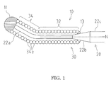
- FIG. 1 is a partial cross-sectional enlarged view illustrating a first embodiment of a guide wire of the present invention.
- the left side corresponds to a distal side to be inserted in a body
- the right side corresponds to a proximal side to be operated by a technician such as a physician.
- FIG. 1 schematically illustrates the guide wire, and the proportion in FIG. 1 is different from actual one.
- a guide wire 10 illustrated in FIG. 1 is used to facilitate positioning of a catheter in a cardiovascular system, for example.
- the guide wire 10 includes a core shaft 20 and a coil body 30 covering the outer periphery of the distal portion of the core shaft 20.
- the core shaft 20 includes a small diameter portion 22a, a taper portion 22b, and a large diameter portion 22c, in this order from the distal end to the proximal side.
- the small diameter portion 22a is a portion on the most distal end of the core shaft 20, and is a softest portion in the core shaft 20.
- the small diameter portion 22a is formed to be a flat plate shape by press working.
- the taper portion 22b is tapered with a circular cross-section, and is reduced in diameter toward the distal side.
- the large diameter portion 22c has a larger diameter than the small diameter portion 22a.
- the material composing the core shaft 20 is not especially limited, and includes stainless steel (SUS304), a super-elastic alloy such as a Ni-Ti alloy, a piano wire, or a cobalt alloy, for example.
- the coil body 30 of the first embodiment is a single wound coil formed by winding a single wire into a helical coil structure.
- the coil body 30 comprises a plurality of turns (loops) 34a arranged one after the other in a longitudinal direction of the coil body 30.
- the single wire forming the coil body 30 is an example of a (single) winding element in the claims.
- the distal end of the coil body 30 is fixed to the distal end of the core shaft 20 by a distal side joint portion 11.
- the proximal end of the coil body 30 is fixed to the core shaft 20 by a proximal side joint portion 13.
- the material composing the distal side joint portion 11 and the proximal side joint portion 13 is not especially limited, and includes a brazing metal such as a Sn-Pb alloy, a Pb-Ag alloy, a Sn-Ag alloy, or an Au-Sn alloy, for example.
- the coil body 30 includes a straight section 32 in a straight state from a proximal end toward the distal direction and a curved section 34 arranged at the distal side of the straight section 32.
- the curved section 34 is curved with a predetermined angle relative to an axial direction N of the straight section 32.
- adjacent turns 34a of the coil body 30 are in contact with each other on an outer side of the curved section 34. That is, on the outer side of the curved section 34, no gap is generated between adjacent turns 34a of the single wire.
- the outer side of the curved section 34 is a side opposite to the side to which the curved section 34 is curved, relative to the axial direction N. This applies also in the embodiments described later.
- the turns 34a are separate from each another with a space or gap being provided between adjacent turns 34a on the outer side of the curved section 34, a fragment of a calcified lesion in a stenosis portion, for example, may enter between adjacent turns 34a and cause interference, and the distal portion of the guide wire 10 may be suppressed to move, and the passing performance when the guide wire passes through the stenosis portion may decrease.
- the adjacent turns 34a on the outer side of the curved section 34 are in contact with each other, which prevents a part of a lesion from entering between the turns 34a in the curved section 34. As a result, the distal portion of the guide wire 10 is hardly got caught, which sufficiently secures the passing performance when the guide wire passes through the stenosis portion.
- the material composing the coil body 30 is not especially limited, and the coil body 30 may be formed by a radiopaque wire or a radiotransparent wire.
- the material of the radiopaque wire is not especially limited, and includes gold, platinum, tungsten, or an alloy including such elements (e.g., a platinum-nickel alloy), for example.
- the material of the radiotransparent wire is not especially limited, and includes stainless steel (SUS304, SUS316, etc.), a super-elastic alloy such as a Ni-Ti alloy, or a piano wire, for example.
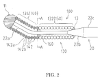
- FIG. 2 schematically illustrates the guide wire, and the proportion in FIG. 2 , including the configuration of the cross-section of the stranded wire, is different from actual one.
- a guide wire 100 of the second embodiment includes a coil body 130 comprising a first coil portion 140 forming a curved section 134 and a second coil portion 150 forming a straight section 132.
- the first coil portion 140 forming the curved section 134 is formed by winding a plurality of stranded wires 142, which are each obtained by stranding a plurality of single wires 142a, 142b, into a helical coil structure.
- the plurality of stranded wires 142 is an example of a plurality of winding elements in the claims.
- a single stranded wire 142 is an example of a single winding element in the claims.
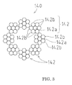
- the first coil portion 140 forming the curved section 134 is formed by winding a plurality of (eight in the embodiment) the stranded wires 142, each of which includes a core wire 142a and six side wires 142b wound to cover the periphery of the core wire 142a, into a helical coil structure.
- the material composing the core wire 142a and the side wires 142b is not especially limited, and includes stainless steel such as martensitic stainless steel, ferritic stainless steel, austenitic stainless steel, austenite-ferrite duplex stainless steel, or a precipitation hardening type stainless steel; a super-elastic alloy such as a Ni-Ti alloy; or platinum, gold, tungsten, tantalum, iridium, or an alloy including such elements, which are radiopaque metal impermeable to radiation such as X-rays, for example.
- stainless steel such as martensitic stainless steel, ferritic stainless steel, austenitic stainless steel, austenite-ferrite duplex stainless steel, or a precipitation hardening type stainless steel
- a super-elastic alloy such as a Ni-Ti alloy
- the first coil portion 140 forming the curved section 134 is formed by winding the stranded wires 142, which are each obtained by stranding the single wires 142a, 142b, into a helical coil structure.
- the stranded wires 142 are in close contact with each other firmly.
- the stranded wires 142 do not separate from each other and a gap is hardly generated therebetween.
- the distal portion When the stress is added to the distal portion (the curved section 134) of the guide wire 100, relative slight movement is possible not only between the stranded wires 142 but also between the single wires 142a, 142b forming the stranded wires 142.
- the distal portion has a high degree of freedom and excellent flexibility while being resistant to plastic deformation and securing a preferable restoring characteristic. Consequently, excellent following property and selectivity are obtained even in a blood vessel bent three-dimensionally in a complicated manner. Furthermore, even when the distal portion of the guide wire 100 hits a lesion having high hardness, the distal portion is not bent by stress exerted by the hit and the guide wire can be used continuously.
- the second coil body 150 forming the straight section 132 is formed by a single-wound coil obtained by winding a single wire into a helical coil structure.
- Such single wire is an example of a single winding element in the claims.
- the material composing the second coil body 150 is not especially limited, and the second coil body may be formed by a radiopaque wire or a radiotransparent wire.
- the material of the radiopaque wire is not especially limited, and includes gold, platinum, tungsten, or an alloy including such elements (e.g., a platinum-nickel alloy), for example.
- the material of the radiotransparent wire is not especially limited, and includes stainless steel (SUS304, SUS316, etc.), a super-elastic alloy such as a Ni-Ti alloy, and a piano wire, for example.
- the proximal end of the first coil portion 140 and the distal end of the second coil portion 150 are joined to each other by an intermediate joint portion 160.
- the material composing the intermediate joint portion 160 is not especially limited, and includes a brazing metal such as a Sn-Pb alloy, a Pb-Ag alloy, a Sn-Ag alloy, and an Au-Sn alloy, for example.
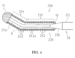
- FIG. 4 schematically illustrates the guide wire, and the proportion in FIG. 4 , including the configuration of the cross-section of the stranded wire, is different from actual one.
- a guide wire 200 of the third embodiment not only a curved section 234 but also a straight section 232 is formed by winding a plurality of stranded wires 242, which are each obtained by stranding a plurality of single wires, into a helical coil structure.
- the coil body 230 is configured entirely by winding a plurality of stranded wires 242, which are obtained by stranding a plurality of single wires 242a, into a helical coil structure. Note that the structure of the coil body 230 is same as the first coil portion of the second embodiment described above.
- the stranded wires 242 are in close contact with each other, similarly to the second embodiment, and a gap is hardly generated when the curved section 234 is formed.
- the coil body 230 of the third embodiment is formed entirely by winding a plurality of the stranded wires 242, which are obtained by stranding a plurality of the single wires 242a, into a helical coil structure, and thus the stranded wires positioned at a border portion K between the straight section 232 and the curved section 234 are in pressure contact with each other firmly.
- the single wires 242a are fastened by each other and the stranded wires 242 are also fastened by each other, which increases contact pressure and improves the adherence, when a rotational force is added. Consequently, the torque transmission performance is improved, and the preferable passing performance of the guide wire 200 is secured.
- a stranding angle or winding angle ⁇ 1 of the first stranded wires 252 forming the curved section 234 is larger than a stranding angle or winding angle ⁇ 2 of the second stranded wires 262 forming the straight section 232.
- the first stranded wires 252 forming the curved section 234 erect along a vertical direction, and come to press the second stranded wires 262 forming the straight section 232 in an axial direction N.
- the stranding angle ⁇ 1 of the first stranded wires 252 is an angle on an acute angle side defined by the axial direction N of the straight section 232 and the winding direction of the first stranded wires 252, while the stranding angle ⁇ 2 of the second stranded wires 262 is an angle on an acute angle side defined by the axial direction N of the straight section 232 and the winding direction of the second stranded wires 262. This applies also in the embodiment described later.
- first stranded wires 252 forming the curved section 234 are arranged substantially in parallel in a part X. Such a structure prevents a first stranded wire 252 forming the curved section 234 from deviating relatively from an adjacent first stranded wire 252 and separating therefrom, and no gap is formed between turns of the stranded wires 252 forming the curved section 234.
- the adjacent first stranded wires 252 are in pressure contact with each other. In this manner, it is possible to securely prevent generation of a gap between the first stranded wires 252 forming the curved section 234 of the guide wire 200.
- FIG. 6 schematically illustrates the guide wire, and the proportion in FIG. 6 , including the configuration of the cross-section of the stranded wire, is different from actual one.
- a straight section 332 of a coil body 330 is tapered to a smaller diameter toward a curved section 334 (the distal side). That is, in the straight section 332, an outer diameter ⁇ 1 at a portion on the curved section 334 side (the distal side) is smaller than an outer diameter ⁇ 2 at a position on the rear side (the proximal side).
- the stranding angle or winding angle ⁇ 2 of the second stranded wires 362 forming the straight section 332 becomes gradually smaller toward the curved section 334 side (the distal side), and the second stranded wires 362 come to press the first stranded wires 352 forming the curved section 334, from the proximal side, as illustrated in FIG. 7 .
- the stranded wires 352, 362 are in pressure contact with each other firmly at a border portion L between the curved section 334 and the straight section 332.
- the diameter is smallest at the proximal end part of the curved section 334, which improves flexibility of the curved section 334.
- the diameter becomes larger from the distal side to the proximal side.
- sliding resistance to a blood vessel wall becomes larger toward the proximal side.
- the distal portion (the curved section 334) of the guide wire 300 penetrates through a blood vessel wall and projects outside the blood vessel, and the operation is still continued thereafter, the sliding resistance of the straight section 332 to the blood vessel wall (a wall of the through-hole) becomes larger gradually, thus conveying such touch feeling to a hand of an operator.
- the guide wire 300 of the fourth embodiment allows insertion of the distal portion to a target region safely and accurately. Furthermore, in such a case, with the use of a coil body whose outer diameter becomes smaller toward the distal side, the sliding resistance to a blood vessel wall, for example, in press-in operation further becomes larger toward the proximal side, thus easily conveying touch feeling in press-in operation in the guide wire to a hand of an operator.
Landscapes
- Health & Medical Sciences (AREA)
- Life Sciences & Earth Sciences (AREA)
- Biophysics (AREA)
- Pulmonology (AREA)
- Engineering & Computer Science (AREA)
- Anesthesiology (AREA)
- Biomedical Technology (AREA)
- Heart & Thoracic Surgery (AREA)
- Hematology (AREA)
- Animal Behavior & Ethology (AREA)
- General Health & Medical Sciences (AREA)
- Public Health (AREA)
- Veterinary Medicine (AREA)
- Media Introduction/Drainage Providing Device (AREA)
Abstract
Description
- The present invention relates to a guide wire used as a medical device inserted in a body cavity for treatment or examination.
- Conventionally, there are proposed various medical devices inserted in a tubular organ such as a blood vessel, a gastrointestinal tract, and a urinary duct, or a body tissue for treatment or examination.
- For example, Japanese Unexamined Patent Application Publication No.
2007-501648 - When a degree of a stenosis of a blood vessel is relatively serious as a stenosis portion typically known as a chronic total occlusion (CTO), it is preferable to shape a guide wire in considerably short range from the distal end in order to allow the guide wire to pass through a slight gap in the stenosis portion, as performed in the guide wire described in Japanese Unexamined Patent Application Publication No.
2007-501648 - However, in the guide wire including a curved section by such shaping, a fragment of a calcified lesion in a stenosis portion, for example, enters between a gap of element wires positioned in the curved section and causes interference, and the distal portion of the guide wire is suppressed to move and becomes difficult to move, that is, the situation may cause a stuck of the guide wire. Such the situation decreases the passing performance when the guide wire passes through the stenosis portion.
- Even the guide wire described in Japanese Unexamined Patent Application Publication No.
2007-501648 - In view of the above aspects, the present invention aims at providing a guide wire capable of avoiding a situation in which a distal portion of the guide wire is got caught and stuck in a stenosis portion and securing a sufficient passing performance in the stenosis portion.
- In order to solve the above problem, the guide wire according to an aspect of the present invention has the following characteristics.
- A guide wire according to the first aspect is a guide wire including a core shaft and a coil body comprising a plurality of turns wound around a distal portion of the core shaft, wherein the coil body is formed by winding at least one winding element into a helical coil structure, the coil body includes a straight section in a straight state from a proximal end of the coil body toward a distal direction and a curved section arranged at a distal side of the straight section, and adjacent turns of the coil body are in contact with each other on an outer side of the curved section.
- The second aspect of the present invention is the guide wire according to the first aspect, wherein each of the at least one winding element is formed of a single wire.
- The third aspect of the present invention is the guide wire according to the first aspect, wherein each of the at least one winding element is obtained by stranding a plurality of wires.
- The fourth aspect of the present invention is the guide wire according to any one of the first to third aspects, wherein the coil body is formed by winding a single winding element into a helical coil structure.
- The fifth aspect of the present invention is the guide wire according to the first aspect, wherein the coil body comprises a first coil portion forming the curved section and a second coil portion forming the straight section, wherein the first coil portion is formed by winding a plurality of winding elements into a helical coil structure with each winding element being obtained by stranding a plurality of wires, and wherein the second coil portion is formed of a single wire winding element wound into a helical coil structure.
- The sixth aspect of the present invention is the guide wire according to the fifth aspect, wherein a proximal end of the first coil portion and a distal end of the second coil portion are joined to each other.
- The seventh aspect of the present invention is the guide wire according to any one of the first to third aspects, wherein the coil body is formed by winding a plurality of winding elements into a helical coil structure.
- The eighth aspect of the present invention is the guide wire according to the seventh aspect, wherein a winding angle of first winding elements forming the curved section with respect to a longitudinal axis of the straight section is larger than a winding angle of second winding elements forming the straight section with respect to the longitudinal axis of the straight section.
- The ninth aspect of the present invention is the guide wire according to the seventh aspect or the eighth aspect, wherein the first winding elements forming the curved section are partially arranged substantially in parallel.
- The tenth aspect of the present invention is the guide wire according to any one of the seventh aspect to the ninth aspect, wherein the first winding elements forming the curved section are in pressure contact with each other.
- The eleventh aspect of the present invention is the guide wire according to any one of the seventh aspect to the tenth aspect, wherein the straight section is tapered to a smaller diameter toward the curved section.
- In the coil body used in the guide wire of the first aspect, the coil body comprises a plurality of turns (loops) formed by winding at least one winding element (a single winding element or a plurality of winding elements) into a helical coil structure so that adjacent turns of the coil body on the outer side of the curved section are in contact with each other. If the adjacent turns on the outer side of the curved section are separate from each other with a space, a fragment of a calcified lesion in a stenosis portion, for example, may enter into the gaps between adjacent turns of the at least one winding element and cause interference, and the distal portion of the guide wire may be suppressed to move, and the passing performance when the guide wire passes through the stenosis portion may decrease. However, in the first aspect, adjacent turns of the coil body on the outer side of the curved section are in contact with each other, which prevents a fragment of a lesion from entering between the adjacent turns in the curved section. As a result, the distal portion of the guide wire is hardly got caught, which sufficiently secures the passing performance when the guide wire passes through the stenosis portion.
- In the guide wire of the second and third aspects, each of the at least one winding element is formed either of a single wire or is obtained by stranding a plurality of wires (the plurality of stranded wires may also be referred to as a "stranded wire"). In any case, the turns of the at least one winding element on the outside of the curved section are in contact with each other. If the turns on the outer side of the curved section are separate from each another and provided with a space, a fragment of a calcified lesion in a stenosis portion, for example, may enter between the element wires and cause interference, and the distal portion of the guide wire may be suppressed to move, and the passing performance when the guide wire passes through the stenosis portion may decrease. However, as the turns on the outer side of the curved section are in contact with each other, a fragment of a lesion is prevented from entering between the turns of the at least one winding element in the curved section. As a result, the distal portion of the guide wire is hardly got caught, which sufficiently secures the passing performance when the guide wire passes through the stenosis portion.
- In the guide wire of the fourth aspect, the coil body is formed by winding a single winding element into a helical coil structure. The single winding element may be formed of a single wire or may be obtained by stranding a plurality of wires.
- In the guide wire of the fifth aspect, the coil body is composed of a first coil portion and a second coil portion wherein the first coil portion is formed of a stranded winding element wound into a helical coil structure and the second coil portion is formed of a single wire winding element wound into a helical coil structure.
- In the guide wire of the sixth aspect, the first coil portion and second coil portion are joined to each other, e.g. by applying a bonding material, in particular a brazing metal, to a border portion between a proximal end of the first coil portion and a distal end of the second coil portion.
- In the guide wire of the seventh aspect, the coil body is formed by winding a plurality of winding elements into a helical coil structure. Each of the plurality of winding elements may formed of a single wire or may be obtained by stranding a plurality of wires (the plurality of stranded wires may also be referred to as a "stranded wire").
- For example, in the guide wire of the eighth aspect, the coil body is formed by winding a plurality of winding elements, which are obtained by stranding single wires, into a helical coil structure. The stranded wires are in close contact with each other firmly, and thus even when the curved section is formed, the stranded wires do not separate from each other, and a gap is hardly generated. Therefore, it is possible to securely prevent a fragment of a lesion from entering the curved section.
- Moreover, when the stress is added to the distal portion (the curved section) of the guide wire, relative slight movement is possible not only between stranded wires but also between element wires forming the stranded wires. Thus, the distal portion has a high degree of freedom and excellent flexibility while being resistant to plastic deformation and securing a preferable restoring characteristic. Consequently, excellent following property and selectivity are obtained even in a blood vessel bent three-dimensionally in a complicated manner. Furthermore, even when the distal portion of the guide wire hits a lesion having high hardness, the distal portion is not bent by stress exerted by the hit and the guide wire can be used continuously.
- In the guide wire of the eighth aspect, a (stranding angle or) winding angle of the first winding elements, e.g. stranded wires, forming the curved section with respect to a longitudinal axis of the straight section is larger than a (stranding or) winding angle of the second windingelements,e.g.stranded wires,formingthestraight section. In this manner, when the distal portion of the guide wire is curved, the first winding elements forming the curved section erect along a vertical direction, and come to press the second winding elements forming the straight section in an axial direction. That is, it is possible to secure the contact between the winding elements even in a part where a gap is easily generated between the winding elements (a boundary part between the straight section and the curved section) when the distal portion of the guide wire is curved.
- The guide wire of the ninth aspect includes a part where the first winding elements, e. g. stranded wires, forming the curved section are arranged substantially in parallel. That is, such a structure prevents the first winding elements forming the curved section from deviating relatively from the adjacent first stranded wire and separating therefrom, and no gap is generated between the turns of the winding elements forming the curved section. This prevents a fragment of a lesion, for example, from entering between the turns of the winding elements in the curved section. Thus, the distal portion of the guide wire is hardly got caught, which secures the favorable passing performance when the guide wire passes through a stenosis portion.
- In the guide wire of the tenth aspect, the first winding elements, e.g. stranded wires, forming the curved section are in pressure contact with each other. In this manner, it is possible to securely prevent generation of a gap between the turns of the winding elements forming the curved section of the guide wire.
- In the eleventh aspect, the straight section of the coil body is tapered to a smaller diameter toward the curved section (the distal side). In this manner, the winding angle of the second winding elements, e.g. the stranding angle of the second stranded wires, forming the straight section becomes smaller toward the curved section, and the second winding elements come to press the first winding elements, e.g. stranded wires, forming the curved section. That is, the turns of the winding elements are in pressure contact with each other firmly at the border portion between the curved section and the straight section. As a result, it is possible to prevent more securely generation of a gap between the turns of the winding elements positioned at the border portion between the curved section and the straight section.
- Moreover, the diameter is smallest at the proximal end part of the curved section, which improves the flexibility of the curved section. Therefore, even in a blood vessel bent three-dimensionally in a complicated manner, it is possible to sufficiently secure the blood vessel following property and the blood vessel selectivity of the distal portion of the guide wire.
- In addition, in the straight section of the guide wire of the eleventh aspect, the diameter becomes larger from the distal side to the proximal side. Thus, when the press-in operation is performed, sliding resistance to a blood vessel wall, for example, becomes larger toward the proximal side. Therefore, if the distal portion (the curved section) of the guide wire penetrates through a blood vessel wall and projects outside the blood vessel, and the operation is still continued thereafter, the sliding resistance of the straight section to the blood vessel wall (a wall of the through-hole) becomes larger gradually, thus conveying such touch feeling to a hand of an operator.
- Consequently, it becomes easy to stop the press-in operation in the guide wire once and introduce again the distal portion of the guide wire to a proper blood vessel. That is, the guide wire of the eleventh aspect allows insertion of the distal portion to a target region safely and accurately.
-
-
FIG. 1 is a partial cross-sectional enlarged view illustrating a first embodiment of a guide wire of the present invention; -
FIG. 2 is a partial cross-sectional enlarged view illustrating a second embodiment of the guide wire of the present invention; -
FIG. 3 is a cross-sectional view taken from A-A of a coil body inFIG. 2 ; -
FIG. 4 is a partial cross-sectional enlarged view illustrating a third embodiment of the guide wire of the present invention; -
FIG. 5 is a partial enlarged view illustrating a curved section of a coil body inFIG. 4 and the vicinity thereof; -
FIG. 6 is a partial cross-sectional enlarged view illustrating a fourth embodiment of the guide wire of the present invention; and -
FIG. 7 is a partial enlarged view illustrating a curved section of a coil body inFIG. 6 and the vicinity thereof. - The guide wire of the present invention will be described based on preferred embodiments illustrated in the enclosed drawings.
-
FIG. 1 is a partial cross-sectional enlarged view illustrating a first embodiment of a guide wire of the present invention. InFIG. 1 , the left side corresponds to a distal side to be inserted in a body, while the right side corresponds to a proximal side to be operated by a technician such as a physician. Note thatFIG. 1 schematically illustrates the guide wire, and the proportion inFIG. 1 is different from actual one. - A
guide wire 10 illustrated inFIG. 1 is used to facilitate positioning of a catheter in a cardiovascular system, for example. Theguide wire 10 includes acore shaft 20 and acoil body 30 covering the outer periphery of the distal portion of thecore shaft 20. - First, the
core shaft 20 is described. Thecore shaft 20 includes asmall diameter portion 22a, ataper portion 22b, and alarge diameter portion 22c, in this order from the distal end to the proximal side. Thesmall diameter portion 22a is a portion on the most distal end of thecore shaft 20, and is a softest portion in thecore shaft 20. Thesmall diameter portion 22a is formed to be a flat plate shape by press working. Thetaper portion 22b is tapered with a circular cross-section, and is reduced in diameter toward the distal side. Thelarge diameter portion 22c has a larger diameter than thesmall diameter portion 22a. - The material composing the
core shaft 20 is not especially limited, and includes stainless steel (SUS304), a super-elastic alloy such as a Ni-Ti alloy, a piano wire, or a cobalt alloy, for example. - Next, the
coil body 30 is described. Thecoil body 30 of the first embodiment is a single wound coil formed by winding a single wire into a helical coil structure. Thecoil body 30 comprises a plurality of turns (loops) 34a arranged one after the other in a longitudinal direction of thecoil body 30. The single wire forming thecoil body 30 is an example of a (single) winding element in the claims. - As illustrated in
FIG. 1 , the distal end of thecoil body 30 is fixed to the distal end of thecore shaft 20 by a distal sidejoint portion 11. The proximal end of thecoil body 30 is fixed to thecore shaft 20 by a proximal sidejoint portion 13. The material composing the distal sidejoint portion 11 and the proximal sidejoint portion 13 is not especially limited, and includes a brazing metal such as a Sn-Pb alloy, a Pb-Ag alloy, a Sn-Ag alloy, or an Au-Sn alloy, for example. - The
coil body 30 includes astraight section 32 in a straight state from a proximal end toward the distal direction and acurved section 34 arranged at the distal side of thestraight section 32. Thecurved section 34 is curved with a predetermined angle relative to an axial direction N of thestraight section 32. - In the first embodiment,
adjacent turns 34a of thecoil body 30 are in contact with each other on an outer side of thecurved section 34. That is, on the outer side of thecurved section 34, no gap is generated betweenadjacent turns 34a of the single wire. - Note that the outer side of the
curved section 34 is a side opposite to the side to which thecurved section 34 is curved, relative to the axial direction N. This applies also in the embodiments described later. - Here, if the
turns 34a are separate from each another with a space or gap being provided betweenadjacent turns 34a on the outer side of thecurved section 34, a fragment of a calcified lesion in a stenosis portion, for example, may enter betweenadjacent turns 34a and cause interference, and the distal portion of theguide wire 10 may be suppressed to move, and the passing performance when the guide wire passes through the stenosis portion may decrease. However, in the first embodiment, theadjacent turns 34a on the outer side of thecurved section 34 are in contact with each other, which prevents a part of a lesion from entering between theturns 34a in thecurved section 34. As a result, the distal portion of theguide wire 10 is hardly got caught, which sufficiently secures the passing performance when the guide wire passes through the stenosis portion. - The material composing the
coil body 30 is not especially limited, and thecoil body 30 may be formed by a radiopaque wire or a radiotransparent wire. The material of the radiopaque wire is not especially limited, and includes gold, platinum, tungsten, or an alloy including such elements (e.g., a platinum-nickel alloy), for example. The material of the radiotransparent wire is not especially limited, and includes stainless steel (SUS304, SUS316, etc.), a super-elastic alloy such as a Ni-Ti alloy, or a piano wire, for example. - Next, the second embodiment of the guide wire of the present invention will be described with reference to
FIG. 2 . InFIG. 2 , the left side corresponds to a distal side to be inserted in a body, while the right side corresponds to a proximal side to be operated by a technician such as a physician. Note thatFIG. 2 schematically illustrates the guide wire, and the proportion inFIG. 2 , including the configuration of the cross-section of the stranded wire, is different from actual one. - The first embodiment described above adopts a single wound coil formed by winding a single wire (single winding element) into a helical coil structure. By contrast, a
guide wire 100 of the second embodiment includes acoil body 130 comprising afirst coil portion 140 forming acurved section 134 and asecond coil portion 150 forming astraight section 132. Thefirst coil portion 140 forming thecurved section 134 is formed by winding a plurality of strandedwires 142, which are each obtained by stranding a plurality ofsingle wires wires 142 is an example of a plurality of winding elements in the claims. Further, a single strandedwire 142 is an example of a single winding element in the claims. - To be more specific, as illustrated in
FIGS. 2 and3 , thefirst coil portion 140 forming thecurved section 134 is formed by winding a plurality of (eight in the embodiment) the strandedwires 142, each of which includes acore wire 142a and sixside wires 142b wound to cover the periphery of thecore wire 142a, into a helical coil structure. - The material composing the
core wire 142a and theside wires 142b is not especially limited, and includes stainless steel such as martensitic stainless steel, ferritic stainless steel, austenitic stainless steel, austenite-ferrite duplex stainless steel, or a precipitation hardening type stainless steel; a super-elastic alloy such as a Ni-Ti alloy; or platinum, gold, tungsten, tantalum, iridium, or an alloy including such elements, which are radiopaque metal impermeable to radiation such as X-rays, for example. - As described above, in the
guide wire 100 of the second embodiment, thefirst coil portion 140 forming thecurved section 134 is formed by winding the strandedwires 142, which are each obtained by stranding thesingle wires curved section 134 having such a structure, the strandedwires 142 are in close contact with each other firmly. Thus, when thecurved section 134 is formed, the strandedwires 142 do not separate from each other and a gap is hardly generated therebetween. - This prevents a fragment of a lesion from entering between adjacent turns in the
curved section 134. As a result, the distal portion of theguide wire 100 is hardly got caught by the lesion, which sufficiently secures the passing performance when the guide wire passes through the stenosis portion. - When the stress is added to the distal portion (the curved section 134) of the
guide wire 100, relative slight movement is possible not only between the strandedwires 142 but also between thesingle wires wires 142. Thus, the distal portion has a high degree of freedom and excellent flexibility while being resistant to plastic deformation and securing a preferable restoring characteristic. Consequently, excellent following property and selectivity are obtained even in a blood vessel bent three-dimensionally in a complicated manner. Furthermore, even when the distal portion of theguide wire 100 hits a lesion having high hardness, the distal portion is not bent by stress exerted by the hit and the guide wire can be used continuously. - Meanwhile, the
second coil body 150 forming thestraight section 132 is formed by a single-wound coil obtained by winding a single wire into a helical coil structure. Such single wire is an example of a single winding element in the claims. The material composing thesecond coil body 150 is not especially limited, and the second coil body may be formed by a radiopaque wire or a radiotransparent wire. The material of the radiopaque wire is not especially limited, and includes gold, platinum, tungsten, or an alloy including such elements (e.g., a platinum-nickel alloy), for example. The material of the radiotransparent wire is not especially limited, and includes stainless steel (SUS304, SUS316, etc.), a super-elastic alloy such as a Ni-Ti alloy, and a piano wire, for example. - The proximal end of the
first coil portion 140 and the distal end of thesecond coil portion 150 are joined to each other by an intermediatejoint portion 160. The material composing the intermediatejoint portion 160 is not especially limited, and includes a brazing metal such as a Sn-Pb alloy, a Pb-Ag alloy, a Sn-Ag alloy, and an Au-Sn alloy, for example. - Next, the third embodiment of the guide wire of the present invention will be described with reference to
FIG. 4 . InFIG. 4 , the left side corresponds to a distal side to be inserted in a body, while the right side corresponds to a proximal side to be operated by a technician such as a physician. Note thatFIG. 4 schematically illustrates the guide wire, and the proportion inFIG. 4 , including the configuration of the cross-section of the stranded wire, is different from actual one. - In the second embodiment described above, only the curved section of the coil body is formed by winding a plurality of stranded wires (winding elements), which are obtained by stranding a plurality of single wires, into a helical coil structure. By contrast, in a
guide wire 200 of the third embodiment, not only acurved section 234 but also astraight section 232 is formed by winding a plurality of strandedwires 242, which are each obtained by stranding a plurality of single wires, into a helical coil structure. That is, in the third embodiment, thecoil body 230 is configured entirely by winding a plurality of strandedwires 242, which are obtained by stranding a plurality ofsingle wires 242a, into a helical coil structure. Note that the structure of thecoil body 230 is same as the first coil portion of the second embodiment described above. - In this structure, the stranded
wires 242 are in close contact with each other, similarly to the second embodiment, and a gap is hardly generated when thecurved section 234 is formed. Particularly, thecoil body 230 of the third embodiment is formed entirely by winding a plurality of the strandedwires 242, which are obtained by stranding a plurality of thesingle wires 242a, into a helical coil structure, and thus the stranded wires positioned at a border portion K between thestraight section 232 and thecurved section 234 are in pressure contact with each other firmly. - That is, even in a portion where a gap is generated easily when the
curved section 234 is formed (the border portion K between thestraight section 232 and the curved section 234), it is possible to effectively prevent generation of such the gap, and securely prevent a fragment of a lesion, for example, from entering between adjacent turns of thecurved section 234. As a result, the distal portion of theguide wire 200 is hardly got caught by the lesion, which sufficiently secures the passing performance when theguide wire 200 passes through the stenosis portion. - Furthermore, in the proximal portion of the coil body 230 (the straight section 232), the
single wires 242a are fastened by each other and the strandedwires 242 are also fastened by each other, which increases contact pressure and improves the adherence, when a rotational force is added. Consequently, the torque transmission performance is improved, and the preferable passing performance of theguide wire 200 is secured. - Here, the structure of the
curved section 234 of the embodiment and the vicinity thereof will be described in detail with reference toFIG. 5 . - As illustrated in
FIG. 5 , a stranding angle or winding angle θ1 of the first strandedwires 252 forming thecurved section 234 is larger than a stranding angle or winding angle θ2 of the second strandedwires 262 forming thestraight section 232. In this manner, when the distal portion of theguide wire 200 is curved, the first strandedwires 252 forming thecurved section 234 erect along a vertical direction, and come to press the second strandedwires 262 forming thestraight section 232 in an axial direction N. - Note that the stranding angle θ1 of the first stranded
wires 252 is an angle on an acute angle side defined by the axial direction N of thestraight section 232 and the winding direction of the first strandedwires 252, while the stranding angle θ2 of the second strandedwires 262 is an angle on an acute angle side defined by the axial direction N of thestraight section 232 and the winding direction of the second strandedwires 262. This applies also in the embodiment described later. - That is, it becomes possible to secure contact between the stranded
wires guide wire 200 is curved (the border portion K between thestraight section 232 and the curved section 234). - Furthermore, the first stranded
wires 252 forming thecurved section 234 are arranged substantially in parallel in a part X. Such a structure prevents a first strandedwire 252 forming thecurved section 234 from deviating relatively from an adjacent first strandedwire 252 and separating therefrom, and no gap is formed between turns of the strandedwires 252 forming thecurved section 234. - This prevents a fragment of a lesion from entering between turns of the first stranded
wires 252 forming thecurved section 234. Thus, the distal portion of theguide wire 200 is hardly got caught, which secures the preferable passing performance when theguide wire 200 passes the stenosis portion. - Moreover, in the
curved section 234, the adjacent first strandedwires 252 are in pressure contact with each other. In this manner, it is possible to securely prevent generation of a gap between the first strandedwires 252 forming thecurved section 234 of theguide wire 200. - Next, the fourth embodiment of the guide wire of the present invention will be described with reference to
FIG. 6 . InFIG. 6 , the left side corresponds to a distal side to be inserted in a body, while the right side corresponds to a proximal side to be operated by a technician such as a physician. Note thatFIG. 6 schematically illustrates the guide wire, and the proportion inFIG. 6 , including the configuration of the cross-section of the stranded wire, is different from actual one. - In a
guide wire 300 of the fourth embodiment, astraight section 332 of acoil body 330 is tapered to a smaller diameter toward a curved section 334 (the distal side). That is, in thestraight section 332, an outer diameter α1 at a portion on thecurved section 334 side (the distal side) is smaller than an outer diameter α2 at a position on the rear side (the proximal side). - In this manner, the stranding angle or winding angle θ2 of the second stranded
wires 362 forming thestraight section 332 becomes gradually smaller toward thecurved section 334 side (the distal side), and the second strandedwires 362 come to press the first strandedwires 352 forming thecurved section 334, from the proximal side, as illustrated inFIG. 7 . - That is, as illustrated in
FIGS. 6 and7 , the strandedwires curved section 334 and thestraight section 332. As a result, it is possible to prevent more securely generation of a gap between turns of the stranded wires 342 (352, 362) even in a portion where a gap is generated easily when the distal portion of theguide wire 300 is curved (the border portion L between thestraight section 332 and the curved section 334). - Moreover, in the embodiment, the diameter is smallest at the proximal end part of the
curved section 334, which improves flexibility of thecurved section 334. Thus, even in a blood vessel curved three-dimensionally in a complicated manner, it is possible to sufficiently secure excellent blood vessel following property and the blood vessel selectivity of the distal portion of theguide wire 300. - In addition, in the
straight section 332 of theguide wire 300 of the embodiment, the diameter becomes larger from the distal side to the proximal side. Thus, when the press-in operation is performed, sliding resistance to a blood vessel wall, for example, becomes larger toward the proximal side. Thus, if the distal portion (the curved section 334) of theguide wire 300 penetrates through a blood vessel wall and projects outside the blood vessel, and the operation is still continued thereafter, the sliding resistance of thestraight section 332 to the blood vessel wall (a wall of the through-hole) becomes larger gradually, thus conveying such touch feeling to a hand of an operator. - Consequently, it becomes easy to stop the press-in operation in the
guide wire 300 once and introduce again the distal portion of theguide wire 300 to a proper blood vessel. That is, theguide wire 300 of the fourth embodiment allows insertion of the distal portion to a target region safely and accurately. Furthermore, in such a case, with the use of a coil body whose outer diameter becomes smaller toward the distal side, the sliding resistance to a blood vessel wall, for example, in press-in operation further becomes larger toward the proximal side, thus easily conveying touch feeling in press-in operation in the guide wire to a hand of an operator.
Claims (11)
- A guide wire (10; 100; 200; 300), comprising:a core shaft (20); anda coil body (30; 130; 230; 330) comprising a plurality of turns wound around a distal portion of the core shaft (20),wherein the coil body (130, 230, 330) is formed by winding at least one winding element into a helical coil structure, andwherein the coil body (30; 130; 230; 330) includes a straight section (32; 132; 232; 332) in a straight state from a proximal end of the coil body (30; 130; 230; 330) toward a distal direction and a curved section (34; 134; 234; 334) arranged at a distal side of the straight section (32; 132; 232; 332), characterized in thatadjacent turns of the coil body (30; 130; 230; 330) are in contact with each other on an outer side of the curved section (34; 134; 234; 334).
- The guide wire (10) according to claim 1,
wherein each of the at least one winding element is formed of a single wire. - The guide wire (200) according to claim 1,
wherein each of the at least one winding element (242) is obtained by stranding a plurality of wires (242a). - The guide wire (10) according to any one of claims 1 to 3,
wherein the coil body (30) is formed by winding a single winding element into a helical coil structure. - The guide wire (100) according to claim 1,
wherein the coil body (130) comprises a first coil portion (140) forming the curved section (134) and a second coil portion (150) forming the straight section (132),
wherein the first coil portion (140) is formed by winding a plurality of winding elements (142) into a helical coil structure, each winding element (142) being obtained by stranding a plurality of wires (142a, 142b), and
wherein the second coil portion (150) is formed of a single wire winding element wound into a helical coil structure. - The guide wire (100) according to claim 5,
wherein a proximal end of the first coil portion (140) and a distal end of the second coil portion (150) are joined to each other. - The guide wire (200; 300) according to any one of claims 1 to 3,
wherein the coil body (230; 330) is formed by winding a plurality of winding elements (242; 342) into a helical coil structure. - The guide wire (200; 300) according to claim 7,
wherein a winding angle (θ1) of first winding elements (252; 352) forming the curved section (234; 334) with respect to a longitudinal axis (N) of the straight section (232; 332) is larger than a winding angle (θ2) of second winding elements (262; 362) forming the straight section (232; 332) with respect to the longitudinal axis (N) of the straight section (232; 332). - The guide wire (200; 300) according to claim 7 or 8,
wherein the first winding elements (252; 352) forming the curved section (234; 334) are partially arranged substantially in parallel. - The guide wire (200; 300) according to any one of claims 7 to 9,
wherein the first winding elements (252; 352) forming the curved section (234; 334) are in pressure contact with each other. - The guide wire (300) according to any one of claims 7 to 10,
wherein the straight section (332) is tapered to a smaller diameter toward the curved section (334).
Applications Claiming Priority (2)
| Application Number | Priority Date | Filing Date | Title |
|---|---|---|---|
| JP2014032993 | 2014-02-24 | ||
| JP2014228130A JP6294211B2 (en) | 2014-02-24 | 2014-11-10 | Guide wire |
Publications (2)
| Publication Number | Publication Date |
|---|---|
| EP2918306A1 true EP2918306A1 (en) | 2015-09-16 |
| EP2918306B1 EP2918306B1 (en) | 2020-11-04 |
Family
ID=52573625
Family Applications (1)
| Application Number | Title | Priority Date | Filing Date |
|---|---|---|---|
| EP15156272.5A Active EP2918306B1 (en) | 2014-02-24 | 2015-02-24 | Guide wire |
Country Status (4)
| Country | Link |
|---|---|
| US (1) | US10471237B2 (en) |
| EP (1) | EP2918306B1 (en) |
| JP (1) | JP6294211B2 (en) |
| CN (1) | CN104857613B (en) |
Cited By (1)
| Publication number | Priority date | Publication date | Assignee | Title |
|---|---|---|---|---|
| KR20170134305A (en) * | 2016-03-10 | 2017-12-06 | 아사히 인텍크 가부시키가이샤 | Guide wire |
Families Citing this family (27)
| Publication number | Priority date | Publication date | Assignee | Title |
|---|---|---|---|---|
| US8468919B2 (en) | 2008-12-08 | 2013-06-25 | Next Vascular, Llc | Micro-cutting machine for forming cuts in products |
| US12220538B2 (en) | 2008-12-08 | 2025-02-11 | Scientia Vascular, Inc. | Micro-fabricated intravascular devices having varying diameters |
| US11406791B2 (en) | 2009-04-03 | 2022-08-09 | Scientia Vascular, Inc. | Micro-fabricated guidewire devices having varying diameters |
| US10363389B2 (en) | 2009-04-03 | 2019-07-30 | Scientia Vascular, Llc | Micro-fabricated guidewire devices having varying diameters |
| US9950137B2 (en) | 2009-04-03 | 2018-04-24 | Scientia Vascular, Llc | Micro-fabricated guidewire devices formed with hybrid materials |
| WO2016028486A1 (en) * | 2014-08-21 | 2016-02-25 | Boston Scientific Scimed, Inc. | Medical device with support member |
| US11207502B2 (en) | 2016-07-18 | 2021-12-28 | Scientia Vascular, Llc | Guidewire devices having shapeable tips and bypass cuts |
| US11052228B2 (en) | 2016-07-18 | 2021-07-06 | Scientia Vascular, Llc | Guidewire devices having shapeable tips and bypass cuts |
| US10646689B2 (en) | 2016-07-29 | 2020-05-12 | Cephea Valve Technologies, Inc. | Mechanical interlock for catheters |
| WO2018034072A1 (en) * | 2016-08-17 | 2018-02-22 | テルモ株式会社 | Guidewire |
| US11109967B2 (en) | 2016-08-29 | 2021-09-07 | Cephea Valve Technologies, Inc. | Systems and methods for loading and deploying an intravascular device |
| US10821268B2 (en) | 2016-09-14 | 2020-11-03 | Scientia Vascular, Llc | Integrated coil vascular devices |
| US11452541B2 (en) | 2016-12-22 | 2022-09-27 | Scientia Vascular, Inc. | Intravascular device having a selectively deflectable tip |
| WO2018185917A1 (en) * | 2017-04-06 | 2018-10-11 | 朝日インテック株式会社 | Tubular body and tubular body having catheter |
| EP4257173A3 (en) | 2017-05-26 | 2023-11-29 | Scientia Vascular, Inc. | Micro-fabricated medical device having a non-helical cut arrangement |
| JP6917456B2 (en) * | 2017-07-19 | 2021-08-11 | 朝日インテック株式会社 | Guide wire |
| JP6671072B2 (en) * | 2017-10-24 | 2020-03-25 | 朝日インテック株式会社 | Guide wire |
| CN111432870B (en) * | 2018-02-07 | 2022-08-30 | 朝日英达科株式会社 | guide wire |
| US11305095B2 (en) | 2018-02-22 | 2022-04-19 | Scientia Vascular, Llc | Microfabricated catheter having an intermediate preferred bending section |
| US12011555B2 (en) | 2019-01-15 | 2024-06-18 | Scientia Vascular, Inc. | Guidewire with core centering mechanism |
| US12623049B2 (en) | 2019-05-02 | 2026-05-12 | Scientia Vascular, Inc. | Intravascular device with enhanced one-beam cut pattern |
| JP7231735B2 (en) * | 2019-06-21 | 2023-03-01 | 朝日インテック株式会社 | guide wire |
| US12343485B2 (en) | 2020-01-23 | 2025-07-01 | Scientia Vascular, Inc. | High torque guidewire device |
| US12178975B2 (en) | 2020-01-23 | 2024-12-31 | Scientia Vascular, Inc. | Guidewire having enlarged, micro-fabricated distal section |
| JP6994287B2 (en) * | 2020-02-27 | 2022-01-14 | 朝日インテック株式会社 | Guide wire |
| US12296112B2 (en) | 2020-10-05 | 2025-05-13 | Scientia Vascular, Inc. | Microfabricated catheter devices with high axial strength |
| JP7051032B1 (en) | 2021-11-01 | 2022-04-08 | 朝日インテック株式会社 | Guide wire |
Citations (5)
| Publication number | Priority date | Publication date | Assignee | Title |
|---|---|---|---|---|
| US3452742A (en) * | 1966-05-31 | 1969-07-01 | Us Catheter & Instr Corp | Controlled vascular curvable spring guide |
| US4854330A (en) * | 1986-07-10 | 1989-08-08 | Medrad, Inc. | Formed core catheter guide wire assembly |
| JP2007501648A (en) | 2003-08-07 | 2007-02-01 | ブリヴァント リサーチ アンド デベロップメント リミテッド | Guide wire for catheter |
| EP2005988A1 (en) * | 2007-06-22 | 2008-12-24 | Asahi Intecc Co., Ltd. | A medical guide wire |
| EP2505225A2 (en) * | 2011-03-30 | 2012-10-03 | Asahi Intecc Co., Ltd. | Guide wire |
Family Cites Families (10)
| Publication number | Priority date | Publication date | Assignee | Title |
|---|---|---|---|---|
| US5606981A (en) * | 1994-03-11 | 1997-03-04 | C. R. Bard, Inc. | Catheter guidewire with radiopaque markers |
| US6132389A (en) * | 1998-04-23 | 2000-10-17 | Advanced Cardiovascular Systems, Inc. | Proximally tapered guidewire tip coil |
| WO2003043685A2 (en) * | 2001-11-19 | 2003-05-30 | Cardiovascular Systems, Inc | High torque, low profile intravascular guidewire system |
| JP2005185386A (en) | 2003-12-25 | 2005-07-14 | Asahi Intecc Co Ltd | Medical guidewire |
| JP4829684B2 (en) * | 2006-06-02 | 2011-12-07 | 株式会社エフエムディ | Medical guidewire |
| JP3940161B1 (en) * | 2006-07-03 | 2007-07-04 | 朝日インテック株式会社 | Medical guidewire, medical guidewire and microcatheter assembly, and medical guidewire, balloon catheter and guiding catheter assembly |
| JP5392785B2 (en) * | 2010-06-25 | 2014-01-22 | 朝日インテック株式会社 | Medical guidewire |
| JP5273820B2 (en) | 2010-08-10 | 2013-08-28 | 朝日インテック株式会社 | Guide wire |
| JP2013176488A (en) | 2012-02-29 | 2013-09-09 | Asahi Intecc Co Ltd | Guide wire |
| JP2014100300A (en) * | 2012-11-20 | 2014-06-05 | Asahi Intecc Co Ltd | Guide wire |
-
2014
- 2014-11-10 JP JP2014228130A patent/JP6294211B2/en active Active
-
2015
- 2015-01-28 CN CN201510043593.4A patent/CN104857613B/en active Active
- 2015-02-19 US US14/626,066 patent/US10471237B2/en active Active
- 2015-02-24 EP EP15156272.5A patent/EP2918306B1/en active Active
Patent Citations (5)
| Publication number | Priority date | Publication date | Assignee | Title |
|---|---|---|---|---|
| US3452742A (en) * | 1966-05-31 | 1969-07-01 | Us Catheter & Instr Corp | Controlled vascular curvable spring guide |
| US4854330A (en) * | 1986-07-10 | 1989-08-08 | Medrad, Inc. | Formed core catheter guide wire assembly |
| JP2007501648A (en) | 2003-08-07 | 2007-02-01 | ブリヴァント リサーチ アンド デベロップメント リミテッド | Guide wire for catheter |
| EP2005988A1 (en) * | 2007-06-22 | 2008-12-24 | Asahi Intecc Co., Ltd. | A medical guide wire |
| EP2505225A2 (en) * | 2011-03-30 | 2012-10-03 | Asahi Intecc Co., Ltd. | Guide wire |
Cited By (3)
| Publication number | Priority date | Publication date | Assignee | Title |
|---|---|---|---|---|
| KR20170134305A (en) * | 2016-03-10 | 2017-12-06 | 아사히 인텍크 가부시키가이샤 | Guide wire |
| EP3248644A4 (en) * | 2016-03-10 | 2018-05-02 | Asahi Intecc Co., Ltd. | Guide wire |
| US10493245B2 (en) | 2016-03-10 | 2019-12-03 | Asahi Intecc Co., Ltd. | Guide wire |
Also Published As
| Publication number | Publication date |
|---|---|
| CN104857613A (en) | 2015-08-26 |
| US20150238734A1 (en) | 2015-08-27 |
| EP2918306B1 (en) | 2020-11-04 |
| JP6294211B2 (en) | 2018-03-14 |
| US10471237B2 (en) | 2019-11-12 |
| JP2015171519A (en) | 2015-10-01 |
| CN104857613B (en) | 2020-01-17 |
Similar Documents
| Publication | Publication Date | Title |
|---|---|---|
| EP2918306B1 (en) | Guide wire | |
| EP2689795B1 (en) | Guidewire | |
| EP2962718B1 (en) | Guidewire | |
| EP2361652B1 (en) | Guidewire | |
| JP5382881B2 (en) | Guide wire | |
| JP5067845B2 (en) | Medical guidewire | |
| US8622932B2 (en) | Guidewire | |
| JP5783635B2 (en) | Guide wire | |
| EP2338556A2 (en) | Guidewire | |
| EP2881136B1 (en) | Guidewire | |
| EP2732846A1 (en) | Guidewire | |
| EP2502645A1 (en) | Guidewire | |
| US20150238735A1 (en) | Guide wire | |
| EP2937109B1 (en) | Guidewire | |
| EP2896426B1 (en) | Stranded wire and guidewire employing the same | |
| JP6148587B2 (en) | Guide wire | |
| JP2013176488A (en) | Guide wire | |
| JP2017070803A (en) | Guide wire | |
| JP3179894U (en) | catheter | |
| JP2015089379A (en) | Guide wire | |
| JP2015077159A (en) | Guide wire |
Legal Events
| Date | Code | Title | Description |
|---|---|---|---|
| PUAI | Public reference made under article 153(3) epc to a published international application that has entered the european phase |
Free format text: ORIGINAL CODE: 0009012 |
|
| AK | Designated contracting states |
Kind code of ref document: A1 Designated state(s): AL AT BE BG CH CY CZ DE DK EE ES FI FR GB GR HR HU IE IS IT LI LT LU LV MC MK MT NL NO PL PT RO RS SE SI SK SM TR |
|
| AX | Request for extension of the european patent |
Extension state: BA ME |
|
| 17P | Request for examination filed |
Effective date: 20160223 |
|
| RBV | Designated contracting states (corrected) |
Designated state(s): AL AT BE BG CH CY CZ DE DK EE ES FI FR GB GR HR HU IE IS IT LI LT LU LV MC MK MT NL NO PL PT RO RS SE SI SK SM TR |
|
| RAP1 | Party data changed (applicant data changed or rights of an application transferred) |
Owner name: ASAHI INTECC CO., LTD. |
|
| GRAP | Despatch of communication of intention to grant a patent |
Free format text: ORIGINAL CODE: EPIDOSNIGR1 |
|
| STAA | Information on the status of an ep patent application or granted ep patent |
Free format text: STATUS: GRANT OF PATENT IS INTENDED |
|
| INTG | Intention to grant announced |
Effective date: 20200520 |
|
| RAP1 | Party data changed (applicant data changed or rights of an application transferred) |
Owner name: ASAHI INTECC CO., LTD. |
|
| GRAS | Grant fee paid |
Free format text: ORIGINAL CODE: EPIDOSNIGR3 |
|
| GRAA | (expected) grant |
Free format text: ORIGINAL CODE: 0009210 |
|
| STAA | Information on the status of an ep patent application or granted ep patent |
Free format text: STATUS: THE PATENT HAS BEEN GRANTED |
|
| RIN1 | Information on inventor provided before grant (corrected) |
Inventor name: KANAZAWA, YUYA |
|
| AK | Designated contracting states |
Kind code of ref document: B1 Designated state(s): AL AT BE BG CH CY CZ DE DK EE ES FI FR GB GR HR HU IE IS IT LI LT LU LV MC MK MT NL NO PL PT RO RS SE SI SK SM TR |
|
| REG | Reference to a national code |
Ref country code: GB Ref legal event code: FG4D |
|
| REG | Reference to a national code |
Ref country code: CH Ref legal event code: EP |
|
| REG | Reference to a national code |
Ref country code: AT Ref legal event code: REF Ref document number: 1330014 Country of ref document: AT Kind code of ref document: T Effective date: 20201115 |
|
| REG | Reference to a national code |
Ref country code: IE Ref legal event code: FG4D |
|
| REG | Reference to a national code |
Ref country code: DE Ref legal event code: R096 Ref document number: 602015061380 Country of ref document: DE |
|
| REG | Reference to a national code |
Ref country code: NL Ref legal event code: MP Effective date: 20201104 |
|
| REG | Reference to a national code |
Ref country code: AT Ref legal event code: MK05 Ref document number: 1330014 Country of ref document: AT Kind code of ref document: T Effective date: 20201104 |
|
| PG25 | Lapsed in a contracting state [announced via postgrant information from national office to epo] |
Ref country code: GR Free format text: LAPSE BECAUSE OF FAILURE TO SUBMIT A TRANSLATION OF THE DESCRIPTION OR TO PAY THE FEE WITHIN THE PRESCRIBED TIME-LIMIT Effective date: 20210205 Ref country code: RS Free format text: LAPSE BECAUSE OF FAILURE TO SUBMIT A TRANSLATION OF THE DESCRIPTION OR TO PAY THE FEE WITHIN THE PRESCRIBED TIME-LIMIT Effective date: 20201104 Ref country code: FI Free format text: LAPSE BECAUSE OF FAILURE TO SUBMIT A TRANSLATION OF THE DESCRIPTION OR TO PAY THE FEE WITHIN THE PRESCRIBED TIME-LIMIT Effective date: 20201104 Ref country code: PT Free format text: LAPSE BECAUSE OF FAILURE TO SUBMIT A TRANSLATION OF THE DESCRIPTION OR TO PAY THE FEE WITHIN THE PRESCRIBED TIME-LIMIT Effective date: 20210304 Ref country code: NO Free format text: LAPSE BECAUSE OF FAILURE TO SUBMIT A TRANSLATION OF THE DESCRIPTION OR TO PAY THE FEE WITHIN THE PRESCRIBED TIME-LIMIT Effective date: 20210204 |
|
| PG25 | Lapsed in a contracting state [announced via postgrant information from national office to epo] |
Ref country code: PL Free format text: LAPSE BECAUSE OF FAILURE TO SUBMIT A TRANSLATION OF THE DESCRIPTION OR TO PAY THE FEE WITHIN THE PRESCRIBED TIME-LIMIT Effective date: 20201104 Ref country code: IS Free format text: LAPSE BECAUSE OF FAILURE TO SUBMIT A TRANSLATION OF THE DESCRIPTION OR TO PAY THE FEE WITHIN THE PRESCRIBED TIME-LIMIT Effective date: 20210304 Ref country code: SE Free format text: LAPSE BECAUSE OF FAILURE TO SUBMIT A TRANSLATION OF THE DESCRIPTION OR TO PAY THE FEE WITHIN THE PRESCRIBED TIME-LIMIT Effective date: 20201104 Ref country code: LV Free format text: LAPSE BECAUSE OF FAILURE TO SUBMIT A TRANSLATION OF THE DESCRIPTION OR TO PAY THE FEE WITHIN THE PRESCRIBED TIME-LIMIT Effective date: 20201104 Ref country code: ES Free format text: LAPSE BECAUSE OF FAILURE TO SUBMIT A TRANSLATION OF THE DESCRIPTION OR TO PAY THE FEE WITHIN THE PRESCRIBED TIME-LIMIT Effective date: 20201104 Ref country code: AT Free format text: LAPSE BECAUSE OF FAILURE TO SUBMIT A TRANSLATION OF THE DESCRIPTION OR TO PAY THE FEE WITHIN THE PRESCRIBED TIME-LIMIT Effective date: 20201104 Ref country code: BG Free format text: LAPSE BECAUSE OF FAILURE TO SUBMIT A TRANSLATION OF THE DESCRIPTION OR TO PAY THE FEE WITHIN THE PRESCRIBED TIME-LIMIT Effective date: 20210204 |
|
| REG | Reference to a national code |
Ref country code: LT Ref legal event code: MG9D |
|
| PG25 | Lapsed in a contracting state [announced via postgrant information from national office to epo] |
Ref country code: HR Free format text: LAPSE BECAUSE OF FAILURE TO SUBMIT A TRANSLATION OF THE DESCRIPTION OR TO PAY THE FEE WITHIN THE PRESCRIBED TIME-LIMIT Effective date: 20201104 |
|
| PG25 | Lapsed in a contracting state [announced via postgrant information from national office to epo] |
Ref country code: SK Free format text: LAPSE BECAUSE OF FAILURE TO SUBMIT A TRANSLATION OF THE DESCRIPTION OR TO PAY THE FEE WITHIN THE PRESCRIBED TIME-LIMIT Effective date: 20201104 Ref country code: RO Free format text: LAPSE BECAUSE OF FAILURE TO SUBMIT A TRANSLATION OF THE DESCRIPTION OR TO PAY THE FEE WITHIN THE PRESCRIBED TIME-LIMIT Effective date: 20201104 Ref country code: LT Free format text: LAPSE BECAUSE OF FAILURE TO SUBMIT A TRANSLATION OF THE DESCRIPTION OR TO PAY THE FEE WITHIN THE PRESCRIBED TIME-LIMIT Effective date: 20201104 Ref country code: SM Free format text: LAPSE BECAUSE OF FAILURE TO SUBMIT A TRANSLATION OF THE DESCRIPTION OR TO PAY THE FEE WITHIN THE PRESCRIBED TIME-LIMIT Effective date: 20201104 Ref country code: EE Free format text: LAPSE BECAUSE OF FAILURE TO SUBMIT A TRANSLATION OF THE DESCRIPTION OR TO PAY THE FEE WITHIN THE PRESCRIBED TIME-LIMIT Effective date: 20201104 Ref country code: CZ Free format text: LAPSE BECAUSE OF FAILURE TO SUBMIT A TRANSLATION OF THE DESCRIPTION OR TO PAY THE FEE WITHIN THE PRESCRIBED TIME-LIMIT Effective date: 20201104 |
|
| REG | Reference to a national code |
Ref country code: DE Ref legal event code: R097 Ref document number: 602015061380 Country of ref document: DE |
|
| PG25 | Lapsed in a contracting state [announced via postgrant information from national office to epo] |
Ref country code: DK Free format text: LAPSE BECAUSE OF FAILURE TO SUBMIT A TRANSLATION OF THE DESCRIPTION OR TO PAY THE FEE WITHIN THE PRESCRIBED TIME-LIMIT Effective date: 20201104 |
|
| PLBE | No opposition filed within time limit |
Free format text: ORIGINAL CODE: 0009261 |
|
| STAA | Information on the status of an ep patent application or granted ep patent |
Free format text: STATUS: NO OPPOSITION FILED WITHIN TIME LIMIT |
|
| PG25 | Lapsed in a contracting state [announced via postgrant information from national office to epo] |
Ref country code: MC Free format text: LAPSE BECAUSE OF FAILURE TO SUBMIT A TRANSLATION OF THE DESCRIPTION OR TO PAY THE FEE WITHIN THE PRESCRIBED TIME-LIMIT Effective date: 20201104 |
|
| 26N | No opposition filed |
Effective date: 20210805 |
|
| REG | Reference to a national code |
Ref country code: BE Ref legal event code: MM Effective date: 20210228 |
|
| PG25 | Lapsed in a contracting state [announced via postgrant information from national office to epo] |
Ref country code: LU Free format text: LAPSE BECAUSE OF NON-PAYMENT OF DUE FEES Effective date: 20210224 Ref country code: NL Free format text: LAPSE BECAUSE OF FAILURE TO SUBMIT A TRANSLATION OF THE DESCRIPTION OR TO PAY THE FEE WITHIN THE PRESCRIBED TIME-LIMIT Effective date: 20201104 Ref country code: LI Free format text: LAPSE BECAUSE OF NON-PAYMENT OF DUE FEES Effective date: 20210228 Ref country code: AL Free format text: LAPSE BECAUSE OF FAILURE TO SUBMIT A TRANSLATION OF THE DESCRIPTION OR TO PAY THE FEE WITHIN THE PRESCRIBED TIME-LIMIT Effective date: 20201104 Ref country code: CH Free format text: LAPSE BECAUSE OF NON-PAYMENT OF DUE FEES Effective date: 20210228 Ref country code: IT Free format text: LAPSE BECAUSE OF FAILURE TO SUBMIT A TRANSLATION OF THE DESCRIPTION OR TO PAY THE FEE WITHIN THE PRESCRIBED TIME-LIMIT Effective date: 20201104 |
|
| PG25 | Lapsed in a contracting state [announced via postgrant information from national office to epo] |
Ref country code: SI Free format text: LAPSE BECAUSE OF FAILURE TO SUBMIT A TRANSLATION OF THE DESCRIPTION OR TO PAY THE FEE WITHIN THE PRESCRIBED TIME-LIMIT Effective date: 20201104 |
|
| PG25 | Lapsed in a contracting state [announced via postgrant information from national office to epo] |
Ref country code: IE Free format text: LAPSE BECAUSE OF NON-PAYMENT OF DUE FEES Effective date: 20210224 |
|
| PG25 | Lapsed in a contracting state [announced via postgrant information from national office to epo] |
Ref country code: IS Free format text: LAPSE BECAUSE OF FAILURE TO SUBMIT A TRANSLATION OF THE DESCRIPTION OR TO PAY THE FEE WITHIN THE PRESCRIBED TIME-LIMIT Effective date: 20210304 |
|
| PG25 | Lapsed in a contracting state [announced via postgrant information from national office to epo] |
Ref country code: BE Free format text: LAPSE BECAUSE OF NON-PAYMENT OF DUE FEES Effective date: 20210228 |
|
| PG25 | Lapsed in a contracting state [announced via postgrant information from national office to epo] |
Ref country code: HU Free format text: LAPSE BECAUSE OF FAILURE TO SUBMIT A TRANSLATION OF THE DESCRIPTION OR TO PAY THE FEE WITHIN THE PRESCRIBED TIME-LIMIT; INVALID AB INITIO Effective date: 20150224 |
|
| PG25 | Lapsed in a contracting state [announced via postgrant information from national office to epo] |
Ref country code: CY Free format text: LAPSE BECAUSE OF FAILURE TO SUBMIT A TRANSLATION OF THE DESCRIPTION OR TO PAY THE FEE WITHIN THE PRESCRIBED TIME-LIMIT Effective date: 20201104 |
|
| PG25 | Lapsed in a contracting state [announced via postgrant information from national office to epo] |
Ref country code: MK Free format text: LAPSE BECAUSE OF FAILURE TO SUBMIT A TRANSLATION OF THE DESCRIPTION OR TO PAY THE FEE WITHIN THE PRESCRIBED TIME-LIMIT Effective date: 20201104 |
|
| PG25 | Lapsed in a contracting state [announced via postgrant information from national office to epo] |
Ref country code: MT Free format text: LAPSE BECAUSE OF FAILURE TO SUBMIT A TRANSLATION OF THE DESCRIPTION OR TO PAY THE FEE WITHIN THE PRESCRIBED TIME-LIMIT Effective date: 20201104 |
|
| PG25 | Lapsed in a contracting state [announced via postgrant information from national office to epo] |
Ref country code: TR Free format text: LAPSE BECAUSE OF FAILURE TO SUBMIT A TRANSLATION OF THE DESCRIPTION OR TO PAY THE FEE WITHIN THE PRESCRIBED TIME-LIMIT Effective date: 20201104 |
|
| PGFP | Annual fee paid to national office [announced via postgrant information from national office to epo] |
Ref country code: GB Payment date: 20260219 Year of fee payment: 12 |
|
| PGFP | Annual fee paid to national office [announced via postgrant information from national office to epo] |
Ref country code: DE Payment date: 20260218 Year of fee payment: 12 |
|
| PGFP | Annual fee paid to national office [announced via postgrant information from national office to epo] |
Ref country code: FR Payment date: 20260218 Year of fee payment: 12 |