EP2918192A1 - Folding table - Google Patents
Folding table Download PDFInfo
- Publication number
- EP2918192A1 EP2918192A1 EP13853046.4A EP13853046A EP2918192A1 EP 2918192 A1 EP2918192 A1 EP 2918192A1 EP 13853046 A EP13853046 A EP 13853046A EP 2918192 A1 EP2918192 A1 EP 2918192A1
- Authority
- EP
- European Patent Office
- Prior art keywords
- table body
- brackets
- use state
- lock pin
- folding table
- Prior art date
- Legal status (The legal status is an assumption and is not a legal conclusion. Google has not performed a legal analysis and makes no representation as to the accuracy of the status listed.)
- Granted
Links
Images


Classifications
-
- A—HUMAN NECESSITIES
- A47—FURNITURE; DOMESTIC ARTICLES OR APPLIANCES; COFFEE MILLS; SPICE MILLS; SUCTION CLEANERS IN GENERAL
- A47B—TABLES; DESKS; OFFICE FURNITURE; CABINETS; DRAWERS; GENERAL DETAILS OF FURNITURE
- A47B5/00—Suspended or hinged panels forming a table; Wall tables
- A47B5/006—Suspended or hinged panels forming a table; Wall tables brought into operative position through a combination of translational and rotational movement
-
- A—HUMAN NECESSITIES
- A47—FURNITURE; DOMESTIC ARTICLES OR APPLIANCES; COFFEE MILLS; SPICE MILLS; SUCTION CLEANERS IN GENERAL
- A47B—TABLES; DESKS; OFFICE FURNITURE; CABINETS; DRAWERS; GENERAL DETAILS OF FURNITURE
- A47B5/00—Suspended or hinged panels forming a table; Wall tables
- A47B5/04—Suspended or hinged panels forming a table; Wall tables foldable
-
- B—PERFORMING OPERATIONS; TRANSPORTING
- B60—VEHICLES IN GENERAL
- B60N—SEATS SPECIALLY ADAPTED FOR VEHICLES; VEHICLE PASSENGER ACCOMMODATION NOT OTHERWISE PROVIDED FOR
- B60N3/00—Arrangements or adaptations of other passenger fittings, not otherwise provided for
- B60N3/001—Arrangements or adaptations of other passenger fittings, not otherwise provided for of tables or trays
- B60N3/002—Arrangements or adaptations of other passenger fittings, not otherwise provided for of tables or trays of trays
- B60N3/004—Arrangements or adaptations of other passenger fittings, not otherwise provided for of tables or trays of trays of foldable trays mounted on the back-rest
-
- E—FIXED CONSTRUCTIONS
- E05—LOCKS; KEYS; WINDOW OR DOOR FITTINGS; SAFES
- E05D—HINGES OR SUSPENSION DEVICES FOR DOORS, WINDOWS OR WINGS
- E05D3/00—Hinges with pins
- E05D3/06—Hinges with pins with two or more pins
- E05D3/12—Hinges with pins with two or more pins with two parallel pins and one arm
-
- E—FIXED CONSTRUCTIONS
- E05—LOCKS; KEYS; WINDOW OR DOOR FITTINGS; SAFES
- E05D—HINGES OR SUSPENSION DEVICES FOR DOORS, WINDOWS OR WINGS
- E05D3/00—Hinges with pins
- E05D3/06—Hinges with pins with two or more pins
- E05D3/18—Hinges with pins with two or more pins with sliding pins or guides
Definitions
- the present invention relates to a folding table configured by making a simple change to a conventional folding table to prevent insertion of foreign matters into a hole or holes.
- FIG. 7 is a perspective view showing a configuration of a shaft part of a folding table disclosed in Patent Document 1 listed below.
- a table body 102 has a hinge pin 105 which is fitted in a shaft hole of a bracket 103.
- the table body 102 can be pivoted about the hinge pin 105.
- the bracket 103 has a movable hole 110 formed larger than the shaft hole.
- spring members 111 and 112 are installed in this movable hole 110.
- the table body 102 is provided with a lock pin 106 in addition to the hinge pin 105. This lock pin 106 is pressed against the wall of the movable hole 110 so as to be held in each of positions corresponding to the use state and the non-use state of the table body 102.
- Patent Document 1 JP-A-2011-15746
- the movable hole 110 of the table body 102 is always closed by the bracket 103. This is to avoid exposure of the hinge pin 105 and the lock pin 106, in particular, the movable hole 110.
- a movable hole 110 is exposed in a non-use state in which a table body is oriented upright and thus foreign matters may enter in the movable hole 110.
- the table body 102 is tilted with the foreign matters remaining entered, there is a risk that the foreign matters are caught, thus restricting the pivoting operation of the table body 102.
- the conventional example shown in FIG. 7 can address such a problem; however, this conventional example shown in FIG. 7 needs redesign and remanufacturing of a new folding table. This leads to replacement of all the existing tables, resulting in large cost increase.
- the present invention has been made to solve the above problems and has a purpose to provide a folding table configured by utilizing an existing folding table to prevent entrance of foreign matters in a movable hole.
- one aspect of the invention provides a folding table including a table body provided with a pair of hinge pins oppositely protruding on left and right sides and a pair of lock pins oppositely protruding on left and right sides, and a pair of left and right brackets each having a shaft hole in which the hinge pin serving as a pivotal center is inserted and a movable hole in which a spring member is installed to urge the lock pin inserted therein, the table body being supported pivotally by the brackets fixed to a wall surface, wherein the folding table includes closing plates that are plate members each having through holes through which the hinge pin and the lock pin of the table body are penetrated, and the closing plates are individually sandwiched between the table body and the brackets to close the movable holes.
- the through holes through which the hinge pin and the lock pin are individually penetrated are long holes, the through hole through which the lock pin is penetrated is smaller than a moving range of the lock pin to allow the closing plate to slide in association with pivoting of the table body.
- a part of the closing plate has a shape conforming to outer shapes of the table body and the brackets seen from side in a use state in which the table body is tilted down and in a non-use state in which the table body is oriented upright.
- each of the brackets includes a step on an open side of the movable hole to define a movable range in which the closing plate is allowed to slide, so that each of the brackets provides a recessed area corresponding to the movable range.
- the closing plates are positioned by abutting on the steps.
- a closing plate is provided to be sandwiched between a table body and a bracket to close or cover a large movable hole to reduce an exposed area of the movable hole, thereby enabling preventing entrance of foreign matters in the movable hole.
- the present invention is configured to prevent entrance of foreign matters by use of the closing plate, so that there is no need to redesign and remanufacture a folding table itself, different from the conventional example.
- the present invention utilizing an existing folding table can achieve the same effects without increasing costs as with the effects in the conventional example.
- FIG. 1 is a plan view showing a use state of the folding table.
- FIG. 2 is a side view showing the use state of the same folding table.
- the folding table 1 is configured, as with the conventional folding table, such that a supporting member 2 is fixed to a wall 80, and a table body 3 is pivotally supported on the supporting member 2.
- the supporting member 2 includes left and right brackets 21 and 22 integrally formed at ends of a fixed part 23.
- the fixed part 23 of the supporting member 2 is fixed to the wall 80 with screws 25 so that the brackets 21 and 22 protrude horizontally from the wall 80.
- the brackets 21 and 22 are removably attached to the fixed part 23 with screws 26.
- the table body 3 has left and right shoulders 31 and 32 formed in a cut-out shape according to the shapes of the brackets 21 and 22 respectively. Each of these shoulders 31 and 32 is provided with two pins protruding therefrom. One of the two pins is a hinge pin 35 serving as a pivotal center of the table body 3 and the other is a lock pin 36 to retain the posture of the table body 3.
- Each of the brackets 21 and 22 of the supporting member 2 is formed with holes receiving the hinge pin 35 and the lock pin 36.
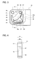
- FIG. 3 is an internal side view of the bracket 21 of the supporting member 2.
- the opposite bracket 22 is configured to be symmetrical to the bracket 21 and thus its figure and explanation are omitted.
- the bracket 21 is a plate-like member having a predetermined thickness as shown in FIG. 1 and is formed with a circular shaft through-hole 41 and a movable hole 42 large enough to allow the lock pin 36 to move.
- a plurality of spring members are mounted and fixed with a bolt 27 and a nut 28.
- Each of the spring members is made of a strip-shaped metal bent in a predetermined shape to urge the lock pin 36.
- These spring members include a spring member 43 having a curved surface along a movement path of the lock pin 36 which will move in a circular arc, and further spring members 44 and 45 elastically supporting the spring member 43, and others.
- the spring member 43 is continuously in pressure contact with the lock pin 36.
- the urging forces of the spring members 44 and 45 act at both end portions of the spring member 43 in a moving direction of the lock pin 36 which will move in a circular arc, that is, at positions of the lock pin 36 indicated by solid lines and broken lines in FIG. 3 .
- the movable hole 42 is formed with recesses 42a and 42b in correspondence with the urging positions so that the spring members 44 and 45 are allowed to warp in a depth direction of each corresponding recess 42a and 42b.
- the bracket 21 is formed with a step 48 to define a movable range 47 provided with the shaft hole 41 and the movable hole 42. Specifically, the bracket 21 has a thin thickness to provide a recessed area corresponding to the movable range 47.
- FIG. 4 is a sectional view of the bracket 21 taken along I-I in FIG. 3 .
- the bracket 21 in the present embodiment is designed with a thickness B1 of 17 mm and the movable range 47 is designed with a thickness B2 of 15 mm.
- the step 48 is formed on an open side of the movable hole 42, thereby providing a gap between the bracket 21 and the table body 3 by an amount corresponding to the step. In this gap, a closing plate 5 having a thickness of 1.7 mm is inserted.
- FIG. 5 is a view showing the closing plate 5.
- This closing plate 5 is placed to close the movable hole 42 of the bracket 21 to prevent foreign matters from entering in the movable hole 42.
- the closing plate 5 has such a shape as shown in the figure having a shaft-side oval through hole 51 through which the hinge pin 35 is penetrated and a movable-hole-side curved oval through hole 52 through which the lock pin 36 is penetrated. These through holes 51 and 52 are both long holes.
- the closing plates 5 are individually held, or sandwiched, between the bracket 21 and the table body 3 and between the bracket 22 and the table body 3 while the hinge pins 35 and the lock pins 36 are penetrated through the closing plates 5 as shown in FIG. 1 .
- the closing plate 5 which is not present in the conventional art is additionally provided and the bracket 21 is formed with the step 48 to receive the closing plate 5.
- the supporting member 2 of the folding table 1 consists of the brackets 21 and 22 integrally fixed to the fixed part 23 with screws.
- the table body 3 and fixed part 23 of the supporting member 2 which are conventionally used are utilized as-is, and the closing plates 5 and the brackets 21 and 22 are newly designed and manufactured.
- the folding table 1 is configured as shown in FIGs. 1 and 2 such that the supporting member 2 is fixed to the wall 80 and the table body 3 is pivotally attached to the brackets 21 and 22.
- the hinge pins 35 and the lock pins 36 of the table body 3 are inserted in the shaft holes 41 and the movable holes 42 of the corresponding brackets 21 and 22.
- the closing plates 5 are put between the table body 3 and the brackets 21 and 22 so that the hinge pins 35 and the lock pins 36 are penetrated respectively through the shaft-side through holes 51 and the movable-hole-side through holes 52.
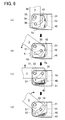
- FIG. 6 are diagrams each showing a state of the closing plate 5 associated with rotating, or pivoting, of the table body 3; (a) to (d) sequentially represent (a) a non-use state in which the table body 3 is oriented upright along the wall, (b) an intermediate state of the table body 3 being tilting down to a use position, (c) a use state in which the table body 3 is horizontally tilted, and (d) an intermediate state of the table body 3 being tilting up to a non-use position.
- the folding table 1 is normally in the non-use state with the table body 3 oriented upright as shown in FIG. 6(a) .
- a rider or passenger seated on the first-row seat will tilt the table body 3 down to the near side (leftward in the figure) in use.
- the table body 3 is pivoted about the hinge pin 35 and inclined as shown in FIG. 6(b) .
- each of the lock pins 36 (see FIG. 3 ) is moved from the position indicated by the broken lines to the position indicated by the solid lines by sliding on the curved surface of the corresponding spring member 43.
- the movable-hole-side through hole 52 of the closing plate 5 is short than the moving range of the lock pin 36.
- the shaft-side through hole 51 for the hinge pin 35 is designed as an oval hole, not a circular hole, and the movable-hole-side through hole 52 is formed smaller, or shorter, than the moving range of the lock pin 36 as described above. This is to allow the closing plate 5 to slide, so that the size of the closing plate 5 itself is reduced. Because of the reduced size of the closing plate 5, the closing plate 5 is less likely to protrude from the table body 3 and the bracket 21 when seen from side in the non-use state in FIG. 6(a) and the use state in FIG. 6(c) .
- the closing plate 5 is intended to close the movable hole 42 but configured not to protrude from the table body 3 and the bracket 21.
- a part of the closing plate 5 has a shape conforming to the outer shapes of the table body 3 and the bracket 21 seen from side in the non-use state (a) and the use state (c).
- the closing plate 5 has such a shape that two straight sides 5a and 5b abut on the step 48 of the bracket 21 respectively in the non-use state (a) and the use state (c) to position the closing plate 5.
- the closing plate 5 In the use state in which the table body 3 is horizontally oriented as shown in FIG. 6(c) , the closing plate 5 is positioned in place with the side 5b abutting on the step 48.
- the urging force of the spring members act on the lock pin 36 to retain the posture of the table body 3, thereby preventing the table body 3 from rattling due to vibration while the vehicle is running.
- the lock pin 36 located at the position indicated by the solid lines in FIG. 3 presses a return portion of the spring member 45 toward the recess 42a and thus is pressed against the protecting plate 46 by the reaction force of the spring member 45. In this way, the table body 3 of the folding table 1 is retained in the use state.
- a passenger or rider orients the table body 3 in the upright position in such a way so as to flip up a distal end of the table body 3 from the state shown in FIG. 6(c) .
- the table body 3 is pivoted about the hinge pins 35 and tilted as shown in FIG. 6(d) .
- the lock pin 36 (see FIG. 3 ) is caused to slide on the curved surface of the spring member 43 and move from the position indicated by the solid lines to the position indicated by the broken lines.
- the closing plate 5 is slid downward as shown in FIG. 6(d) . Since the moving path of the lock pin 36 does not coincide with the shape of the movable-hole-side through hole 52, the closing plate 5 is pushed down by the lock pin 36 moving within the movable-hole-side through hole 52. Thereafter, the closing plate 5 is also slid in a rotation direction and then positioned with the side 5a abutting on the step 48 as shown in FIG. 6(a) . Thus, the table body 3 is made upright and the folding table 1 comes to the non-use state.
- the table body 3 can be maintained upright in the non-use state without tilting down due to vibrations even during running. Specifically, the lock pin 36 located at the position shown by the broken lines in FIG. 3 presses a return portion of the spring member 44 toward the recess 42b and thus is pressed against the protecting plate 46 by the reaction force of the spring member 44. In this way, the folding table 1 is retained in the non-use state with the table body 3 oriented upright.
- the folding table 1 in the present embodiment will be switched between the non-use state shown in FIG. 6(a) and the use state shown in FIG. 6(c) as described above.
- the closing plate 5 covers the movable hole 42.
- the closing plate 5 has such a shape as not to protrude out of the table body 3 and the bracket 21 in each of the use state and the non-use state to reduce an exposed portion of the movable hole 42.
- the closing plate 5 cannot completely close the movable hole 42; however, the spring members 43, 44, and 45 and the nut are present in such an exposed portion and thus there is little space even in the use state shown in FIG. 6(c) . This can effectively prevent entrance of foreign matters in the movable hole 42.
- the present embodiment does not need to redesign and remanufacture the folding table itself, differently from the conventional example and enables utilization of an existing one. This can achieve the aforementioned effects similar to those in the conventional example without increasing costs.
- the closing plates 5 and the brackets 21 and 22 each provided with the step 48 for receiving the closing plate 5.
- existing ones can be directly utilized.
- the closing plate 5 is shaped so as to overlap the table body 3 and the bracket 21 without protruding out in each of the use state and the non-use state. Accordingly, even the closing plate 5 which is a thin plate having a thickness of about 1.7 mm is less likely to hit or bump against something and be broken.
- the closing plate 5 is guided to be slid or positioned by the step 48, so that the closing plate 5 is stably placed in each of the use state and the non-use state or moved between them.
- each bracket itself may be moved outward to the right and left and fixed thereat to allow each closing plate to be sandwiched between the corresponding bracket and the table body 3.
Landscapes
- Engineering & Computer Science (AREA)
- Mechanical Engineering (AREA)
- Transportation (AREA)
- Passenger Equipment (AREA)
- Tables And Desks Characterized By Structural Shape (AREA)
- Ladders (AREA)
Abstract
Description
- The present invention relates to a folding table configured by making a simple change to a conventional folding table to prevent insertion of foreign matters into a hole or holes.
- For instance, high-speed rail vehicles and the like are provided with a table for each seat. For a first-row seat, particularly, a table is provided so that a table body is pivotally mounted on brackets fixed to a front wall. The folding table is configured such that the table body is able to rotate, or pivot, between a non-use state in which the table body is oriented upright along the wall and a use state in which the table body is tilted horizontally.
FIG. 7 is a perspective view showing a configuration of a shaft part of a folding table disclosed inPatent Document 1 listed below. - In this folding table 100, a
table body 102 has ahinge pin 105 which is fitted in a shaft hole of abracket 103. Thetable body 102 can be pivoted about thehinge pin 105. Thebracket 103 has amovable hole 110 formed larger than the shaft hole. In thismovable hole 110,spring members table body 102 is provided with alock pin 106 in addition to thehinge pin 105. Thislock pin 106 is pressed against the wall of themovable hole 110 so as to be held in each of positions corresponding to the use state and the non-use state of thetable body 102. - Patent Document 1:
JP-A-2011-15746 - Meanwhile, in the conventional folding table shown in
FIG. 7 , themovable hole 110 of thetable body 102 is always closed by thebracket 103. This is to avoid exposure of thehinge pin 105 and thelock pin 106, in particular, themovable hole 110. In other conventional folding tables than that shown inFIG. 7 , amovable hole 110 is exposed in a non-use state in which a table body is oriented upright and thus foreign matters may enter in themovable hole 110. When thetable body 102 is tilted with the foreign matters remaining entered, there is a risk that the foreign matters are caught, thus restricting the pivoting operation of thetable body 102. This makes thetable body 102 unusable or breaks a part or parts thereof if thistable body 102 is forced to pivot. In this regard, the conventional example shown inFIG. 7 can address such a problem; however, this conventional example shown inFIG. 7 needs redesign and remanufacturing of a new folding table. This leads to replacement of all the existing tables, resulting in large cost increase. - The present invention has been made to solve the above problems and has a purpose to provide a folding table configured by utilizing an existing folding table to prevent entrance of foreign matters in a movable hole.
- To achieve the above purpose, one aspect of the invention provides a folding table including a table body provided with a pair of hinge pins oppositely protruding on left and right sides and a pair of lock pins oppositely protruding on left and right sides, and a pair of left and right brackets each having a shaft hole in which the hinge pin serving as a pivotal center is inserted and a movable hole in which a spring member is installed to urge the lock pin inserted therein, the table body being supported pivotally by the brackets fixed to a wall surface, wherein the folding table includes closing plates that are plate members each having through holes through which the hinge pin and the lock pin of the table body are penetrated, and the closing plates are individually sandwiched between the table body and the brackets to close the movable holes.
- In the folding table in the above aspect of the invention, preferably, the through holes through which the hinge pin and the lock pin are individually penetrated are long holes, the through hole through which the lock pin is penetrated is smaller than a moving range of the lock pin to allow the closing plate to slide in association with pivoting of the table body.
- In the folding table in the above aspect of the invention, preferably, a part of the closing plate has a shape conforming to outer shapes of the table body and the brackets seen from side in a use state in which the table body is tilted down and in a non-use state in which the table body is oriented upright.
- In the folding table in the above aspect of the invention, preferably, each of the brackets includes a step on an open side of the movable hole to define a movable range in which the closing plate is allowed to slide, so that each of the brackets provides a recessed area corresponding to the movable range.
- In the folding table in the above aspect of the invention, preferably, in a use state in which the table body is tilted down and a non-use state in which table body is oriented upright, the closing plates are positioned by abutting on the steps.
- According to the present invention, a closing plate is provided to be sandwiched between a table body and a bracket to close or cover a large movable hole to reduce an exposed area of the movable hole, thereby enabling preventing entrance of foreign matters in the movable hole. In particular, the present invention is configured to prevent entrance of foreign matters by use of the closing plate, so that there is no need to redesign and remanufacture a folding table itself, different from the conventional example. The present invention utilizing an existing folding table can achieve the same effects without increasing costs as with the effects in the conventional example.
-
-
FIG. 1 is a plan view showing a use state of a folding table in an embodiment; -
FIG. 2 is a side view showing the use state of the folding table in the embodiment; -
FIG. 3 is an internal side view of a bracket of the folding table; -
FIG. 4 is a sectional view of the bracket taken along I-I inFIG. 3 ; -
FIG. 5 is a view of a closing plate; -
FIG. 6 are diagrams each showing a state of the closing plate associated with pivoting of a table body; and -
FIG. 7 is a perspective view showing a configuration of a shaft part of a conventional folding table. - A detailed description of a preferred embodiment of a folding table embodying the present invention will now be given referring to the accompanying drawings. The folding table in this embodiment will be explained as one used in a railway carriage. Specifically, a folding table provided on a wall in front of a first-row seat will be explained.
FIG. 1 is a plan view showing a use state of the folding table.FIG. 2 is a side view showing the use state of the same folding table. - The folding table 1 is configured, as with the conventional folding table, such that a supporting
member 2 is fixed to awall 80, and atable body 3 is pivotally supported on the supportingmember 2. The supportingmember 2 includes left andright brackets fixed part 23. Thefixed part 23 of the supportingmember 2 is fixed to thewall 80 withscrews 25 so that thebrackets wall 80. Thebrackets fixed part 23 withscrews 26. - The
table body 3 has left andright shoulders 31 and 32 formed in a cut-out shape according to the shapes of thebrackets shoulders 31 and 32 is provided with two pins protruding therefrom. One of the two pins is ahinge pin 35 serving as a pivotal center of thetable body 3 and the other is alock pin 36 to retain the posture of thetable body 3. Each of thebrackets member 2 is formed with holes receiving thehinge pin 35 and thelock pin 36.FIG. 3 is an internal side view of thebracket 21 of the supportingmember 2. Theopposite bracket 22 is configured to be symmetrical to thebracket 21 and thus its figure and explanation are omitted. - The
bracket 21 is a plate-like member having a predetermined thickness as shown inFIG. 1 and is formed with a circular shaft through-hole 41 and amovable hole 42 large enough to allow thelock pin 36 to move. In themovable hole 42, a plurality of spring members are mounted and fixed with abolt 27 and anut 28. Each of the spring members is made of a strip-shaped metal bent in a predetermined shape to urge thelock pin 36. These spring members include aspring member 43 having a curved surface along a movement path of thelock pin 36 which will move in a circular arc, andfurther spring members spring member 43, and others. - The
spring member 43 is continuously in pressure contact with thelock pin 36. In particular, the urging forces of thespring members spring member 43 in a moving direction of thelock pin 36 which will move in a circular arc, that is, at positions of thelock pin 36 indicated by solid lines and broken lines inFIG. 3 . Themovable hole 42 is formed withrecesses spring members corresponding recess - In the
movable hole 42, protectingplates 46 are fitted one at each of positions corresponding to both ends in the moving direction of thelock pin 36. Therefore, thelock pin 36 located in either end in the moving direction is pressed against the protectingplate 46 by reaction force of thespring member recess lock pin 36 is thus positioned, retaining thetable body 3 in the use state or non-use state. The position of thelock pin 36 illustrated with the solid lines represents the use state of the folding table 1 with thetable body 3 tilted horizontally and the position of the same illustrated with the broken lines represents the non-use state of the folding table 1 with thetable body 3 oriented upright along the wall. - The
bracket 21 is formed with astep 48 to define amovable range 47 provided with theshaft hole 41 and themovable hole 42. Specifically, thebracket 21 has a thin thickness to provide a recessed area corresponding to themovable range 47. Herein,FIG. 4 is a sectional view of thebracket 21 taken along I-I inFIG. 3 . Thebracket 21 in the present embodiment is designed with a thickness B1 of 17 mm and themovable range 47 is designed with a thickness B2 of 15 mm. In the present embodiment, thestep 48 is formed on an open side of themovable hole 42, thereby providing a gap between thebracket 21 and thetable body 3 by an amount corresponding to the step. In this gap, aclosing plate 5 having a thickness of 1.7 mm is inserted. -
FIG. 5 is a view showing theclosing plate 5. Thisclosing plate 5 is placed to close themovable hole 42 of thebracket 21 to prevent foreign matters from entering in themovable hole 42. Theclosing plate 5 has such a shape as shown in the figure having a shaft-side oval throughhole 51 through which thehinge pin 35 is penetrated and a movable-hole-side curved oval throughhole 52 through which thelock pin 36 is penetrated. These throughholes closing plates 5 are individually held, or sandwiched, between thebracket 21 and thetable body 3 and between thebracket 22 and thetable body 3 while the hinge pins 35 and the lock pins 36 are penetrated through theclosing plates 5 as shown inFIG. 1 . - In the present embodiment, as above, the
closing plate 5 which is not present in the conventional art is additionally provided and thebracket 21 is formed with thestep 48 to receive theclosing plate 5. The supportingmember 2 of the folding table 1 consists of thebrackets part 23 with screws. For this folding table 1, therefore, thetable body 3 and fixedpart 23 of the supportingmember 2 which are conventionally used are utilized as-is, and theclosing plates 5 and thebrackets - The folding table 1 is configured as shown in
FIGs. 1 and2 such that the supportingmember 2 is fixed to thewall 80 and thetable body 3 is pivotally attached to thebrackets table body 3 are inserted in the shaft holes 41 and themovable holes 42 of thecorresponding brackets closing plates 5 are put between thetable body 3 and thebrackets holes 51 and the movable-hole-side through holes 52. - Next, operations of the folding table 1 will be explained.
FIG. 6 are diagrams each showing a state of theclosing plate 5 associated with rotating, or pivoting, of thetable body 3; (a) to (d) sequentially represent (a) a non-use state in which thetable body 3 is oriented upright along the wall, (b) an intermediate state of thetable body 3 being tilting down to a use position, (c) a use state in which thetable body 3 is horizontally tilted, and (d) an intermediate state of thetable body 3 being tilting up to a non-use position. - The folding table 1 is normally in the non-use state with the
table body 3 oriented upright as shown inFIG. 6(a) . Thus, a rider or passenger seated on the first-row seat will tilt thetable body 3 down to the near side (leftward in the figure) in use. When tilted to the near side, thetable body 3 is pivoted about thehinge pin 35 and inclined as shown inFIG. 6(b) . At that time, each of the lock pins 36 (seeFIG. 3 ) is moved from the position indicated by the broken lines to the position indicated by the solid lines by sliding on the curved surface of thecorresponding spring member 43. The movable-hole-side throughhole 52 of theclosing plate 5 is short than the moving range of thelock pin 36. Thus, thelock pin 36 abuts on the throughhole 52 in the course of movement as shown inFIG. 6(b) , and then theclosing plate 5 is caused to slide by engagement with thelock pin 36. As shownFIG. 6(c) , accordingly, theclosing plate 5 is moved upward in association of movement of thelock pin 36, and thehinge pin 35 relatively shifts downward within the shaft-side throughhole 51. - In the present embodiment, to slid the
closing plate 5 in the above way, the shaft-side throughhole 51 for thehinge pin 35 is designed as an oval hole, not a circular hole, and the movable-hole-side throughhole 52 is formed smaller, or shorter, than the moving range of thelock pin 36 as described above. This is to allow theclosing plate 5 to slide, so that the size of theclosing plate 5 itself is reduced. Because of the reduced size of theclosing plate 5, theclosing plate 5 is less likely to protrude from thetable body 3 and thebracket 21 when seen from side in the non-use state inFIG. 6(a) and the use state inFIG. 6(c) . - Accordingly, the
closing plate 5 is intended to close themovable hole 42 but configured not to protrude from thetable body 3 and thebracket 21. A part of theclosing plate 5 has a shape conforming to the outer shapes of thetable body 3 and thebracket 21 seen from side in the non-use state (a) and the use state (c). Furthermore, theclosing plate 5 has such a shape that twostraight sides step 48 of thebracket 21 respectively in the non-use state (a) and the use state (c) to position theclosing plate 5. In the use state in which thetable body 3 is horizontally oriented as shown inFIG. 6(c) , theclosing plate 5 is positioned in place with theside 5b abutting on thestep 48. - In the use state shown in
FIG. 6(c) , the urging force of the spring members act on thelock pin 36 to retain the posture of thetable body 3, thereby preventing thetable body 3 from rattling due to vibration while the vehicle is running. Specifically, thelock pin 36 located at the position indicated by the solid lines inFIG. 3 presses a return portion of thespring member 45 toward therecess 42a and thus is pressed against the protectingplate 46 by the reaction force of thespring member 45. In this way, thetable body 3 of the folding table 1 is retained in the use state. When the folding table 1 is to be brought in the non-use state, a passenger or rider orients thetable body 3 in the upright position in such a way so as to flip up a distal end of thetable body 3 from the state shown inFIG. 6(c) . At that time, thetable body 3 is pivoted about the hinge pins 35 and tilted as shown inFIG. 6(d) . - The lock pin 36 (see
FIG. 3 ) is caused to slide on the curved surface of thespring member 43 and move from the position indicated by the solid lines to the position indicated by the broken lines. In mid-course thereof, theclosing plate 5 is slid downward as shown inFIG. 6(d) . Since the moving path of thelock pin 36 does not coincide with the shape of the movable-hole-side throughhole 52, theclosing plate 5 is pushed down by thelock pin 36 moving within the movable-hole-side throughhole 52. Thereafter, theclosing plate 5 is also slid in a rotation direction and then positioned with theside 5a abutting on thestep 48 as shown inFIG. 6(a) . Thus, thetable body 3 is made upright and the folding table 1 comes to the non-use state. - Since the lock pins 36 receive the urging forces of the spring members, the
table body 3 can be maintained upright in the non-use state without tilting down due to vibrations even during running. Specifically, thelock pin 36 located at the position shown by the broken lines inFIG. 3 presses a return portion of thespring member 44 toward therecess 42b and thus is pressed against the protectingplate 46 by the reaction force of thespring member 44. In this way, the folding table 1 is retained in the non-use state with thetable body 3 oriented upright. - The folding table 1 in the present embodiment will be switched between the non-use state shown in
FIG. 6(a) and the use state shown inFIG. 6(c) as described above. In each of the above states, theclosing plate 5 covers themovable hole 42. Theclosing plate 5 has such a shape as not to protrude out of thetable body 3 and thebracket 21 in each of the use state and the non-use state to reduce an exposed portion of themovable hole 42. Theclosing plate 5 cannot completely close themovable hole 42; however, thespring members FIG. 6(c) . This can effectively prevent entrance of foreign matters in themovable hole 42. - Since the folding table is particularly configured by use of the
closing plates 5 to prevent entrance of foreign matters in themovable holes 42, the present embodiment does not need to redesign and remanufacture the folding table itself, differently from the conventional example and enables utilization of an existing one. This can achieve the aforementioned effects similar to those in the conventional example without increasing costs. To be concrete, it is only necessary to provide, as new members, theclosing plates 5 and thebrackets step 48 for receiving theclosing plate 5. For thetable body 3 and thespring members 43 to 45 installed in thebrackets - The
closing plate 5 is shaped so as to overlap thetable body 3 and thebracket 21 without protruding out in each of the use state and the non-use state. Accordingly, even theclosing plate 5 which is a thin plate having a thickness of about 1.7 mm is less likely to hit or bump against something and be broken. Theclosing plate 5 is guided to be slid or positioned by thestep 48, so that theclosing plate 5 is stably placed in each of the use state and the non-use state or moved between them. - The folding table according to the present invention is explained in the embodiment as above, but it is not limited thereto. The present invention may be embodied in other specific forms without departing from the essential characteristics thereof. For instance, the aforementioned embodiment ensures the installation space of the
closing plates 5 by forming thesteps 48 in thebrackets table body 3. -
- 1
- Folding table
- 2
- Supporting member
- 3
- Table body
- 5
- Closing plate
- 21, 22
- Bracket
- 35
- Hinge pin
- 36
- Lock pin
- 41
- Shaft hole
- 42
- Movable hole
- 43, 44, 45
- Spring member
- 48
- Step
- 51
- Shaft-side through hole
- 52
- Movable-hole-side through hole
Claims (5)
- A folding table including a table body provided with a pair of hinge pins oppositely protruding on left and right sides and a pair of lock pins oppositely protruding on left and right sides, and a pair of left and right brackets each having a shaft hole in which the hinge pin serving as a pivotal center is inserted and a movable hole in which a spring member is installed to urge the lock pin inserted therein, the table body being supported pivotally by the brackets fixed to a wall surface,
wherein the folding table includes closing plates that are plate members each having through holes through which the hinge pin and the lock pin of the table body are penetrated, and the closing plates are individually sandwiched between the table body and the brackets to close the movable holes. - The folding table according to claim 1, wherein the through holes through which the hinge pin and the lock pin are individually penetrated are long holes, the through hole through which the lock pin is penetrated is smaller than a moving range of the lock pin to allow the closing plate to slide in association with pivoting of the table body.
- The folding table according to claim 2, wherein a part of the closing plate has a shape conforming to outer shapes of the table body and the brackets seen from side in a use state in which the table body is tilted down and in a non-use state in which the table body is oriented upright.
- The folding table according to any one of claims 1 to 3, wherein each of the brackets includes a step on an open side of the movable hole to define a movable range in which the closing plate is allowed to slide, so that each of the brackets provides a recessed area corresponding to the movable range.
- The folding table according to claim 4, wherein
in a use state in which the table body is tilted down and a non-use state in which table body is oriented upright, the closing plates are positioned by abutting on the steps.
Applications Claiming Priority (2)
| Application Number | Priority Date | Filing Date | Title |
|---|---|---|---|
| JP2012245982A JP5467139B1 (en) | 2012-11-08 | 2012-11-08 | Folding table |
| PCT/JP2013/079414 WO2014073432A1 (en) | 2012-11-08 | 2013-10-30 | Folding table |
Publications (3)
| Publication Number | Publication Date |
|---|---|
| EP2918192A1 true EP2918192A1 (en) | 2015-09-16 |
| EP2918192A4 EP2918192A4 (en) | 2015-11-11 |
| EP2918192B1 EP2918192B1 (en) | 2016-09-21 |
Family
ID=50619489
Family Applications (1)
| Application Number | Title | Priority Date | Filing Date |
|---|---|---|---|
| EP13853046.4A Not-in-force EP2918192B1 (en) | 2012-11-08 | 2013-10-30 | Folding table |
Country Status (6)
| Country | Link |
|---|---|
| US (1) | US9380863B2 (en) |
| EP (1) | EP2918192B1 (en) |
| JP (1) | JP5467139B1 (en) |
| CN (1) | CN104797167B (en) |
| TW (1) | TWI604807B (en) |
| WO (1) | WO2014073432A1 (en) |
Families Citing this family (27)
| Publication number | Priority date | Publication date | Assignee | Title |
|---|---|---|---|---|
| USD753578S1 (en) * | 2013-10-28 | 2016-04-12 | Jaguar Land Rover Limited | Vehicle component |
| EP3078548B1 (en) * | 2015-04-09 | 2018-08-29 | Modul-System HH AB | A storage system |
| USD778652S1 (en) * | 2015-07-20 | 2017-02-14 | Brunswick Corporation | Pivotal conference room table |
| US10278496B2 (en) * | 2015-12-17 | 2019-05-07 | M&J Srour Properties Llc | Three parts modular furniture set |
| CN106196819A (en) * | 2016-08-05 | 2016-12-07 | 青岛海尔股份有限公司 | Refrigerator |
| US20180111691A1 (en) * | 2016-10-20 | 2018-04-26 | Molon Labe Llc | Aircraft tray table |
| US10258145B2 (en) * | 2016-11-18 | 2019-04-16 | Onward Multi-Corp Inc. | Shelf attachment assembly |
| USD823620S1 (en) * | 2017-04-30 | 2018-07-24 | Toshikazu Tsukii | Flip top table |
| CN107191081B (en) * | 2017-06-28 | 2018-05-04 | 安徽江淮汽车集团股份有限公司 | A kind of door hinge assy |
| EP3425147B1 (en) | 2017-07-03 | 2023-07-26 | Ningbo Geely Automobile Research & Development Co., Ltd. | A hinge device |
| CN107307582A (en) * | 2017-08-21 | 2017-11-03 | 无锡德兴塑料科技有限公司 | Folding table |
| US10426282B1 (en) | 2018-03-20 | 2019-10-01 | Margaret HAMILTON | Personal foldable server tray apparatus |
| JP2019170847A (en) * | 2018-03-29 | 2019-10-10 | 株式会社東京ボックス | Mounting table |
| USD928696S1 (en) * | 2019-04-16 | 2021-08-24 | Lg Electronics Inc. | Automobile |
| WO2021012652A1 (en) * | 2019-07-23 | 2021-01-28 | 青岛海尔电冰箱有限公司 | Hinge assembly with baffle and refrigerator having same |
| US20220260303A1 (en) * | 2019-07-23 | 2022-08-18 | Qingdao Haier Refrigerator Co., Ltd. | Hinge assembly with decorative sheet and refrigerator having the same |
| CN112282543B (en) * | 2019-07-23 | 2022-07-12 | 青岛海尔电冰箱有限公司 | Refrigerator with a door |
| EP4023975A4 (en) * | 2019-08-28 | 2022-10-19 | Qingdao Haier Refrigerator Co., Ltd | Embedded refrigerator |
| US20220282903A1 (en) * | 2019-08-28 | 2022-09-08 | Qingdao Haier Refrigerator Co., Ltd. | Embedded refrigerator with switching assembly |
| US20220333845A1 (en) * | 2019-08-28 | 2022-10-20 | Qingdao Haier Refrigerator Co., Ltd. | Free embedded refrigerator with increased opening degree |
| CN115110862B (en) * | 2019-08-28 | 2023-11-14 | 青岛海尔电冰箱有限公司 | Hinge assembly and refrigerating device with same |
| US20220282902A1 (en) * | 2019-08-28 | 2022-09-08 | Qingdao Haier Refrigerator Co., Ltd. | Free embedded refrigerator |
| CN110934417B (en) * | 2019-10-29 | 2022-05-13 | 厦门新技术集成有限公司 | Simple folding table |
| US20220081924A1 (en) * | 2020-09-15 | 2022-03-17 | Illinois Grain & Seed, Inc. | Support Platform for a Grain Bin Conditioning System |
| CN112265727B (en) * | 2020-11-25 | 2022-04-01 | 瑞昌市渝瑞实业有限公司 | Yam refrigerating equipment and method |
| CN112757985B (en) * | 2021-02-04 | 2022-02-22 | 麦格纳座椅研发(重庆)有限公司 | Seat table plate with stepless adjustment |
| US11641935B2 (en) | 2021-02-18 | 2023-05-09 | Donald S. Williams | Attachable table apparatus |
Family Cites Families (14)
| Publication number | Priority date | Publication date | Assignee | Title |
|---|---|---|---|---|
| JP2868734B2 (en) * | 1996-07-29 | 1999-03-10 | タキゲン製造株式会社 | Folding table support device |
| US5876092A (en) * | 1997-12-05 | 1999-03-02 | Industrial Technology Research Institute | Foldaway table behind the backrest of a seat |
| JPH11247394A (en) * | 1998-03-03 | 1999-09-14 | Inax Corp | Armrest support structure |
| US6520558B1 (en) * | 1999-02-09 | 2003-02-18 | Decoma Exterior Trim Inc. | Mounting hardware for a hard tonneau cover |
| JP3697993B2 (en) * | 2000-01-25 | 2005-09-21 | 株式会社ノーリツ | Washing counter |
| JP2001311354A (en) * | 2000-05-01 | 2001-11-09 | Nifco Inc | Guide structure of movable body |
| TW567781U (en) * | 2002-12-27 | 2003-12-21 | E Make Co Ltd | Support structure of placement plate |
| US7963231B2 (en) * | 2007-09-21 | 2011-06-21 | Honda Motor Co., Ltd. | Folding table and support frame assembly |
| CN201398631Y (en) * | 2009-04-08 | 2010-02-10 | 章高华 | Switch device of foldable wall table |
| JP5415166B2 (en) * | 2009-07-07 | 2014-02-12 | コンビ株式会社 | Movable table |
| DE102009042879A1 (en) * | 2009-09-24 | 2011-03-31 | GM Global Technology Operations, Inc., Detroit | Folding table for a vehicle |
| US8936308B2 (en) * | 2010-06-18 | 2015-01-20 | B/E Aerospace, Inc. | Aircraft seat with fabric seat back tray |
| CN201759029U (en) * | 2010-08-26 | 2011-03-16 | 章高华 | Folding wall table |
| EP3032986A4 (en) * | 2013-08-12 | 2017-05-17 | Ergo-Industrial Seating Systems Inc. | Pivoting shelf |
-
2012
- 2012-11-08 JP JP2012245982A patent/JP5467139B1/en active Active
-
2013
- 2013-10-30 CN CN201380058370.4A patent/CN104797167B/en not_active Expired - Fee Related
- 2013-10-30 WO PCT/JP2013/079414 patent/WO2014073432A1/en active Application Filing
- 2013-10-30 EP EP13853046.4A patent/EP2918192B1/en not_active Not-in-force
- 2013-10-30 US US14/439,262 patent/US9380863B2/en not_active Expired - Fee Related
- 2013-10-31 TW TW102139482A patent/TWI604807B/en not_active IP Right Cessation
Also Published As
| Publication number | Publication date |
|---|---|
| CN104797167B (en) | 2017-03-29 |
| JP5467139B1 (en) | 2014-04-09 |
| WO2014073432A1 (en) | 2014-05-15 |
| US20150282608A1 (en) | 2015-10-08 |
| CN104797167A (en) | 2015-07-22 |
| TWI604807B (en) | 2017-11-11 |
| US9380863B2 (en) | 2016-07-05 |
| EP2918192B1 (en) | 2016-09-21 |
| EP2918192A4 (en) | 2015-11-11 |
| JP2014094064A (en) | 2014-05-22 |
| TW201433281A (en) | 2014-09-01 |
Similar Documents
| Publication | Publication Date | Title |
|---|---|---|
| EP2918192B1 (en) | Folding table | |
| JP5616116B2 (en) | Slide rail device for vehicle | |
| JP4939810B2 (en) | Vehicle seat slide device | |
| KR20180079390A (en) | Vehicle door checkers | |
| JP2010215028A (en) | Storage box | |
| JP5454257B2 (en) | Deflector device for vehicle | |
| KR100723991B1 (en) | Lock device of seat rail for vehicle | |
| JP5837479B2 (en) | Hinge for game console | |
| JP4933959B2 (en) | hinge | |
| CN101259836A (en) | Device for opening automobile glove box | |
| JP4584042B2 (en) | Locking device bracket | |
| JP4601390B2 (en) | Locking device bracket | |
| JP4510606B2 (en) | Hinge for game console | |
| JP5525752B2 (en) | Locking mechanism of gaming machine | |
| JP7181721B2 (en) | Articulated control panel | |
| JP5681081B2 (en) | Hinge for game console | |
| JP5415883B2 (en) | Vehicle seat slide device | |
| JP4953958B2 (en) | Game machine locking device | |
| JP5525753B2 (en) | Locking mechanism of gaming machine | |
| JP2020029225A (en) | Vehicle slide door device | |
| JP2006233514A (en) | Door opening-closing mechanism of automobile | |
| JP2007252776A (en) | Locking device for game machine | |
| JP5466101B2 (en) | Lid support structure for vehicle accessory case | |
| JP5433292B2 (en) | Locking mechanism of gaming machine | |
| JP6104783B2 (en) | Console Box |
Legal Events
| Date | Code | Title | Description |
|---|---|---|---|
| PUAI | Public reference made under article 153(3) epc to a published international application that has entered the european phase |
Free format text: ORIGINAL CODE: 0009012 |
|
| 17P | Request for examination filed |
Effective date: 20150504 |
|
| AK | Designated contracting states |
Kind code of ref document: A1 Designated state(s): AL AT BE BG CH CY CZ DE DK EE ES FI FR GB GR HR HU IE IS IT LI LT LU LV MC MK MT NL NO PL PT RO RS SE SI SK SM TR |
|
| AX | Request for extension of the european patent |
Extension state: BA ME |
|
| RA4 | Supplementary search report drawn up and despatched (corrected) |
Effective date: 20151009 |
|
| RIC1 | Information provided on ipc code assigned before grant |
Ipc: B60N 3/00 20060101ALI20151005BHEP Ipc: A47B 5/04 20060101AFI20151005BHEP |
|
| DAX | Request for extension of the european patent (deleted) | ||
| REG | Reference to a national code |
Ref country code: DE Ref legal event code: R079 Ref document number: 602013012042 Country of ref document: DE Free format text: PREVIOUS MAIN CLASS: A47B0005040000 Ipc: E05D0003120000 |
|
| GRAP | Despatch of communication of intention to grant a patent |
Free format text: ORIGINAL CODE: EPIDOSNIGR1 |
|
| RIC1 | Information provided on ipc code assigned before grant |
Ipc: E05D 3/12 20060101AFI20160318BHEP Ipc: A47B 5/00 20060101ALI20160318BHEP Ipc: A47B 5/04 20060101ALI20160318BHEP Ipc: B60N 3/00 20060101ALI20160318BHEP Ipc: E05D 3/18 20060101ALI20160318BHEP |
|
| INTG | Intention to grant announced |
Effective date: 20160411 |
|
| GRAS | Grant fee paid |
Free format text: ORIGINAL CODE: EPIDOSNIGR3 |
|
| GRAA | (expected) grant |
Free format text: ORIGINAL CODE: 0009210 |
|
| AK | Designated contracting states |
Kind code of ref document: B1 Designated state(s): AL AT BE BG CH CY CZ DE DK EE ES FI FR GB GR HR HU IE IS IT LI LT LU LV MC MK MT NL NO PL PT RO RS SE SI SK SM TR |
|
| REG | Reference to a national code |
Ref country code: GB Ref legal event code: FG4D |
|
| REG | Reference to a national code |
Ref country code: CH Ref legal event code: EP |
|
| REG | Reference to a national code |
Ref country code: AT Ref legal event code: REF Ref document number: 831213 Country of ref document: AT Kind code of ref document: T Effective date: 20161015 |
|
| REG | Reference to a national code |
Ref country code: IE Ref legal event code: FG4D |
|
| REG | Reference to a national code |
Ref country code: DE Ref legal event code: R096 Ref document number: 602013012042 Country of ref document: DE |
|
| REG | Reference to a national code |
Ref country code: LT Ref legal event code: MG4D Ref country code: NL Ref legal event code: MP Effective date: 20160921 |
|
| PG25 | Lapsed in a contracting state [announced via postgrant information from national office to epo] |
Ref country code: NO Free format text: LAPSE BECAUSE OF FAILURE TO SUBMIT A TRANSLATION OF THE DESCRIPTION OR TO PAY THE FEE WITHIN THE PRESCRIBED TIME-LIMIT Effective date: 20161221 Ref country code: FI Free format text: LAPSE BECAUSE OF FAILURE TO SUBMIT A TRANSLATION OF THE DESCRIPTION OR TO PAY THE FEE WITHIN THE PRESCRIBED TIME-LIMIT Effective date: 20160921 Ref country code: RS Free format text: LAPSE BECAUSE OF FAILURE TO SUBMIT A TRANSLATION OF THE DESCRIPTION OR TO PAY THE FEE WITHIN THE PRESCRIBED TIME-LIMIT Effective date: 20160921 Ref country code: LT Free format text: LAPSE BECAUSE OF FAILURE TO SUBMIT A TRANSLATION OF THE DESCRIPTION OR TO PAY THE FEE WITHIN THE PRESCRIBED TIME-LIMIT Effective date: 20160921 |
|
| REG | Reference to a national code |
Ref country code: AT Ref legal event code: MK05 Ref document number: 831213 Country of ref document: AT Kind code of ref document: T Effective date: 20160921 |
|
| PG25 | Lapsed in a contracting state [announced via postgrant information from national office to epo] |
Ref country code: GR Free format text: LAPSE BECAUSE OF FAILURE TO SUBMIT A TRANSLATION OF THE DESCRIPTION OR TO PAY THE FEE WITHIN THE PRESCRIBED TIME-LIMIT Effective date: 20161222 Ref country code: LV Free format text: LAPSE BECAUSE OF FAILURE TO SUBMIT A TRANSLATION OF THE DESCRIPTION OR TO PAY THE FEE WITHIN THE PRESCRIBED TIME-LIMIT Effective date: 20160921 Ref country code: NL Free format text: LAPSE BECAUSE OF FAILURE TO SUBMIT A TRANSLATION OF THE DESCRIPTION OR TO PAY THE FEE WITHIN THE PRESCRIBED TIME-LIMIT Effective date: 20160921 Ref country code: SE Free format text: LAPSE BECAUSE OF FAILURE TO SUBMIT A TRANSLATION OF THE DESCRIPTION OR TO PAY THE FEE WITHIN THE PRESCRIBED TIME-LIMIT Effective date: 20160921 Ref country code: BE Free format text: LAPSE BECAUSE OF NON-PAYMENT OF DUE FEES Effective date: 20161031 |
|
| PG25 | Lapsed in a contracting state [announced via postgrant information from national office to epo] |
Ref country code: EE Free format text: LAPSE BECAUSE OF FAILURE TO SUBMIT A TRANSLATION OF THE DESCRIPTION OR TO PAY THE FEE WITHIN THE PRESCRIBED TIME-LIMIT Effective date: 20160921 Ref country code: RO Free format text: LAPSE BECAUSE OF FAILURE TO SUBMIT A TRANSLATION OF THE DESCRIPTION OR TO PAY THE FEE WITHIN THE PRESCRIBED TIME-LIMIT Effective date: 20160921 |
|
| REG | Reference to a national code |
Ref country code: DE Ref legal event code: R119 Ref document number: 602013012042 Country of ref document: DE |
|
| PG25 | Lapsed in a contracting state [announced via postgrant information from national office to epo] |
Ref country code: SK Free format text: LAPSE BECAUSE OF FAILURE TO SUBMIT A TRANSLATION OF THE DESCRIPTION OR TO PAY THE FEE WITHIN THE PRESCRIBED TIME-LIMIT Effective date: 20160921 Ref country code: SM Free format text: LAPSE BECAUSE OF FAILURE TO SUBMIT A TRANSLATION OF THE DESCRIPTION OR TO PAY THE FEE WITHIN THE PRESCRIBED TIME-LIMIT Effective date: 20160921 Ref country code: ES Free format text: LAPSE BECAUSE OF FAILURE TO SUBMIT A TRANSLATION OF THE DESCRIPTION OR TO PAY THE FEE WITHIN THE PRESCRIBED TIME-LIMIT Effective date: 20160921 Ref country code: AT Free format text: LAPSE BECAUSE OF FAILURE TO SUBMIT A TRANSLATION OF THE DESCRIPTION OR TO PAY THE FEE WITHIN THE PRESCRIBED TIME-LIMIT Effective date: 20160921 Ref country code: CZ Free format text: LAPSE BECAUSE OF FAILURE TO SUBMIT A TRANSLATION OF THE DESCRIPTION OR TO PAY THE FEE WITHIN THE PRESCRIBED TIME-LIMIT Effective date: 20160921 Ref country code: PT Free format text: LAPSE BECAUSE OF FAILURE TO SUBMIT A TRANSLATION OF THE DESCRIPTION OR TO PAY THE FEE WITHIN THE PRESCRIBED TIME-LIMIT Effective date: 20170123 Ref country code: BG Free format text: LAPSE BECAUSE OF FAILURE TO SUBMIT A TRANSLATION OF THE DESCRIPTION OR TO PAY THE FEE WITHIN THE PRESCRIBED TIME-LIMIT Effective date: 20161221 Ref country code: PL Free format text: LAPSE BECAUSE OF FAILURE TO SUBMIT A TRANSLATION OF THE DESCRIPTION OR TO PAY THE FEE WITHIN THE PRESCRIBED TIME-LIMIT Effective date: 20160921 Ref country code: IS Free format text: LAPSE BECAUSE OF FAILURE TO SUBMIT A TRANSLATION OF THE DESCRIPTION OR TO PAY THE FEE WITHIN THE PRESCRIBED TIME-LIMIT Effective date: 20170121 Ref country code: BE Free format text: LAPSE BECAUSE OF FAILURE TO SUBMIT A TRANSLATION OF THE DESCRIPTION OR TO PAY THE FEE WITHIN THE PRESCRIBED TIME-LIMIT Effective date: 20160921 |
|
| REG | Reference to a national code |
Ref country code: CH Ref legal event code: PL |
|
| PG25 | Lapsed in a contracting state [announced via postgrant information from national office to epo] |
Ref country code: IT Free format text: LAPSE BECAUSE OF FAILURE TO SUBMIT A TRANSLATION OF THE DESCRIPTION OR TO PAY THE FEE WITHIN THE PRESCRIBED TIME-LIMIT Effective date: 20160921 |
|
| REG | Reference to a national code |
Ref country code: IE Ref legal event code: MM4A |
|
| PLBE | No opposition filed within time limit |
Free format text: ORIGINAL CODE: 0009261 |
|
| REG | Reference to a national code |
Ref country code: FR Ref legal event code: ST Effective date: 20170630 |
|
| STAA | Information on the status of an ep patent application or granted ep patent |
Free format text: STATUS: NO OPPOSITION FILED WITHIN TIME LIMIT |
|
| PG25 | Lapsed in a contracting state [announced via postgrant information from national office to epo] |
Ref country code: CH Free format text: LAPSE BECAUSE OF NON-PAYMENT OF DUE FEES Effective date: 20161031 Ref country code: DK Free format text: LAPSE BECAUSE OF FAILURE TO SUBMIT A TRANSLATION OF THE DESCRIPTION OR TO PAY THE FEE WITHIN THE PRESCRIBED TIME-LIMIT Effective date: 20160921 Ref country code: FR Free format text: LAPSE BECAUSE OF NON-PAYMENT OF DUE FEES Effective date: 20161121 Ref country code: LI Free format text: LAPSE BECAUSE OF NON-PAYMENT OF DUE FEES Effective date: 20161031 Ref country code: DE Free format text: LAPSE BECAUSE OF NON-PAYMENT OF DUE FEES Effective date: 20170503 |
|
| 26N | No opposition filed |
Effective date: 20170622 |
|
| PG25 | Lapsed in a contracting state [announced via postgrant information from national office to epo] |
Ref country code: LU Free format text: LAPSE BECAUSE OF NON-PAYMENT OF DUE FEES Effective date: 20161030 |
|
| PG25 | Lapsed in a contracting state [announced via postgrant information from national office to epo] |
Ref country code: SI Free format text: LAPSE BECAUSE OF FAILURE TO SUBMIT A TRANSLATION OF THE DESCRIPTION OR TO PAY THE FEE WITHIN THE PRESCRIBED TIME-LIMIT Effective date: 20160921 Ref country code: IE Free format text: LAPSE BECAUSE OF NON-PAYMENT OF DUE FEES Effective date: 20161030 |
|
| PG25 | Lapsed in a contracting state [announced via postgrant information from national office to epo] |
Ref country code: HU Free format text: LAPSE BECAUSE OF FAILURE TO SUBMIT A TRANSLATION OF THE DESCRIPTION OR TO PAY THE FEE WITHIN THE PRESCRIBED TIME-LIMIT; INVALID AB INITIO Effective date: 20131030 |
|
| GBPC | Gb: european patent ceased through non-payment of renewal fee |
Effective date: 20171030 |
|
| PG25 | Lapsed in a contracting state [announced via postgrant information from national office to epo] |
Ref country code: MC Free format text: LAPSE BECAUSE OF FAILURE TO SUBMIT A TRANSLATION OF THE DESCRIPTION OR TO PAY THE FEE WITHIN THE PRESCRIBED TIME-LIMIT Effective date: 20160921 Ref country code: MK Free format text: LAPSE BECAUSE OF FAILURE TO SUBMIT A TRANSLATION OF THE DESCRIPTION OR TO PAY THE FEE WITHIN THE PRESCRIBED TIME-LIMIT Effective date: 20160921 Ref country code: CY Free format text: LAPSE BECAUSE OF FAILURE TO SUBMIT A TRANSLATION OF THE DESCRIPTION OR TO PAY THE FEE WITHIN THE PRESCRIBED TIME-LIMIT Effective date: 20160921 Ref country code: HR Free format text: LAPSE BECAUSE OF FAILURE TO SUBMIT A TRANSLATION OF THE DESCRIPTION OR TO PAY THE FEE WITHIN THE PRESCRIBED TIME-LIMIT Effective date: 20160921 Ref country code: MT Free format text: LAPSE BECAUSE OF NON-PAYMENT OF DUE FEES Effective date: 20161031 |
|
| PG25 | Lapsed in a contracting state [announced via postgrant information from national office to epo] |
Ref country code: GB Free format text: LAPSE BECAUSE OF NON-PAYMENT OF DUE FEES Effective date: 20171030 |
|
| PG25 | Lapsed in a contracting state [announced via postgrant information from national office to epo] |
Ref country code: AL Free format text: LAPSE BECAUSE OF FAILURE TO SUBMIT A TRANSLATION OF THE DESCRIPTION OR TO PAY THE FEE WITHIN THE PRESCRIBED TIME-LIMIT Effective date: 20160921 Ref country code: TR Free format text: LAPSE BECAUSE OF FAILURE TO SUBMIT A TRANSLATION OF THE DESCRIPTION OR TO PAY THE FEE WITHIN THE PRESCRIBED TIME-LIMIT Effective date: 20160921 |