EP2918180B2 - Optische Prüfung von stabförmigen Artikeln der Tabak verarbeitenden Industrie - Google Patents
Optische Prüfung von stabförmigen Artikeln der Tabak verarbeitenden Industrie Download PDFInfo
- Publication number
- EP2918180B2 EP2918180B2 EP15154819.5A EP15154819A EP2918180B2 EP 2918180 B2 EP2918180 B2 EP 2918180B2 EP 15154819 A EP15154819 A EP 15154819A EP 2918180 B2 EP2918180 B2 EP 2918180B2
- Authority
- EP
- European Patent Office
- Prior art keywords
- rod
- camera
- reflective optical
- path
- optical device
- Prior art date
- Legal status (The legal status is an assumption and is not a legal conclusion. Google has not performed a legal analysis and makes no representation as to the accuracy of the status listed.)
- Active
Links
Images


Classifications
-
- G—PHYSICS
- G01—MEASURING; TESTING
- G01N—INVESTIGATING OR ANALYSING MATERIALS BY DETERMINING THEIR CHEMICAL OR PHYSICAL PROPERTIES
- G01N21/00—Investigating or analysing materials by the use of optical means, i.e. using sub-millimetre waves, infrared, visible or ultraviolet light
- G01N21/84—Systems specially adapted for particular applications
- G01N21/88—Investigating the presence of flaws or contamination
- G01N21/95—Investigating the presence of flaws or contamination characterised by the material or shape of the object to be examined
- G01N21/952—Inspecting the exterior surface of cylindrical bodies or wires
-
- A—HUMAN NECESSITIES
- A24—TOBACCO; CIGARS; CIGARETTES; SIMULATED SMOKING DEVICES; SMOKERS' REQUISITES
- A24C—MACHINES FOR MAKING CIGARS OR CIGARETTES
- A24C5/00—Making cigarettes; Making tipping materials for, or attaching filters or mouthpieces to, cigars or cigarettes
- A24C5/32—Separating, ordering, counting or examining cigarettes; Regulating the feeding of tobacco according to rod or cigarette condition
- A24C5/34—Examining cigarettes or the rod, e.g. for regulating the feeding of tobacco; Removing defective cigarettes
- A24C5/3412—Examining cigarettes or the rod, e.g. for regulating the feeding of tobacco; Removing defective cigarettes by means of light, radiation or electrostatic fields
Definitions
- the invention relates to an image recording device for the optical inspection of rod-shaped articles in the tobacco processing industry, comprising a camera, wherein the camera is configured to simultaneously record at least two images of at least one rod-shaped article or at least one image of at least two rod-shaped articles, wherein for each image, a beam path is provided from the respective rod-shaped article to the camera via at least one first reflective optical device.
- the invention further relates to a method for the optical inspection of rod-shaped articles in the tobacco processing industry, wherein at least two images of at least one rod-shaped article or at least two rod-shaped articles are recorded simultaneously by means of a camera, wherein for each image, rays are transmitted via a beam path from the at least one rod-shaped article via a first reflective optical device to the camera.
- Rod-shaped articles from the tobacco processing industry can be inspected using an inspection device on a conveyor. This preferably occurs during transverse-axial conveying of the articles using an inspection device provided on the conveyor.
- the inspection device comprises, for example, an image recording device and a connected evaluation device.
- the evaluation device has, for example, a computer on which image processing is performed.
- an arrangement for testing rod-shaped articles of the tobacco processing industry comprising a conveyor element for conveying the rod-shaped articles, preferably transversely, and a testing device provided on the conveyor element for testing the rod-shaped articles conveyed on the conveyor element.
- the invention relates to a machine of the tobacco processing industry, in particular a filter attachment machine.
- a filter attachment machine of the patent applicant is known under the name "MAX".
- a filter attachment machine is understood to be a device or machine for producing filter cigarettes with means for receiving tobacco rods of double length with means for cutting these double-length tobacco rods into tobacco rods of single length, with means for inserting filter plugs of double length between the tobacco rods of single length, with means for connecting the double-length filter plug with the two tobacco rods of single length Length by wrapping with a tipping paper sheet which is separated from a fed tipping paper strip by means of a cutting device, with means for subsequently making a separating cut through the double-length filter plug, so that filter cigarettes of normal usage length are produced.
- a leak test and/or at least one head end test and/or a ventilation test and/or at least one visual inspection of the cigarettes are carried out in the filter attachment machine.
- each individual cigarette is pressurized with test air on a test drum. If the measured pressure deviates from a target value, the cigarette in question is defective and is ejected.
- a capacitive sensor for example, checks the tobacco density in the head ends of the cigarettes.
- the cigarettes are pressurized with test air. The measured outlet/inlet pressure ratio is proportional to the cigarette's ventilation level.
- the products or manufactured rod-shaped articles or filter cigarettes are examined using optical inspection devices on a filter attachment machine.
- quality characteristics of the products of the tobacco processing industry are typically detected, such as holes, dimensions, object identification, stamps, glue application, stains, the presence of filter elements, damage, and the like.
- products of the tobacco processing industry are understood to mean, in particular, rod-shaped articles or objects such as cigarettes, filter rods, multi-segment filter rods, and the like.
- Line scan or matrix cameras are typically used for optical inspection. These cameras are equipped with complex, large lenses due to the demands on image and recording quality. For example, to view the entire length of a cigarette without distortion or loss of sharpness, a large distance between the object being measured and the camera is necessary. At some points on machines in the tobacco processing industry, such as a filter attachment machine, the optical path must be folded multiple times using mirrors.
- the illumination of the measurement objects or rod-shaped products in the tobacco processing industry is achieved with separate light sources, which must have high luminous intensities due to the large distance from the object. It is also known, among other things, to guide the light to the measurement object using fiber optic cables, with a loss of intensity. Due to the large distance between the control devices and testing equipment used, flying particles such as tobacco dust, tobacco crumbs, and paper scraps in the dusty environment of a machine in the tobacco processing industry can interfere with the optical inspection and lead to incorrect evaluations. Due to the large distance between the control devices and testing equipment used, this can only be reduced through complex measures.
- DE 10 2004 040 912 A1 a device for the optical inspection of products of the tobacco processing industry is known, which comprises an image capture device, wherein gradient index lenses are used to reduce the distance between the image capture device and the products to be inspected.
- EP 0 812 548 B1 a device for monitoring the external integrity of cigarettes which are conveyed past a plurality of matrix cameras transversely axially on a conveyor drum and are rotated around their longitudinal axis on the conveyor path.
- DE 39 17 321 A1 discloses a method for electro-optical testing of cigarettes, wherein the cigarettes are conveyed along a path defined by two counter-rotating conveyor rollers. Exposed surface halves of each cigarette are inspected by an electro-optical unit, such as a television camera, as they pass over each conveyor roller, while the end face of the cigarette is inspected by at least one further electro-optical unit.
- an electro-optical unit such as a television camera
- the DE 39 17 321 A1 The additional electro-optical unit provided for testing, in particular the ends of the cigarette, is relatively large and cannot be used at every point on a machine in the tobacco processing industry, for example a filter attachment machine.
- US 2005/0185181 A1 A device for optically inspecting an electronic component is disclosed.
- the electronic component is examined from multiple sides using a single camera, using prisms with different refractive indices.
- EP 0 570 163 A2 Another device for optical control of cigarettes is in EP 0 570 163 A2 Two cameras each take two images of the cigarettes' outer surfaces, allowing the entire outer surface to be viewed.
- DE 102 45 559 A1 discloses a camera with an intermediate imaging optics in which a convex and a concave mirror are used to generate the intermediate image.
- EP 1 430 796 A1 A device for optically checking cigarettes is disclosed, in which an image of the outer surfaces of the cigarettes is recorded on a main path and two bypass paths.
- the machine comprises at least one image recording device for the optical inspection of rod-shaped articles of the tobacco processing industry, comprising a camera, wherein the camera is set up to record at least two images of at least one rod-shaped article or at least one image of at least two rod-shaped articles simultaneously, wherein for each image a beam path is provided from the respective rod-shaped article to the camera via at least one first reflective optical device, which is further developed in that each beam path has a path length, wherein the path length of at least one first beam path is or is adapted to the path length of a second beam path by a path length adaptation device.
- the inventive solution allows for very efficient adjustment of the path lengths of the beam paths so that multiple images can be sharply captured even at different distances from the camera. For example, it is possible to set different depths of field of the same objects or the same locations on the respective rod-shaped article, thus enabling sharp images at different depths of the rod-shaped article, for example, at the end of a tobacco rod or at the end of a filter.
- the path length adjustment device enables variable adjustment of the path lengths for rod-shaped articles of different lengths.
- the path length adjustment device is configured to set a first object distance of the first beam path to be as large as a second object distance of the second beam path. This allows objects or surfaces or sides of the at least one rod-shaped article or articles at different distances from the camera to be sharply imaged on the camera simultaneously.
- the camera preferably comprises a light-sensitive image sensor, for example, of the type CMV4000 or CMV2000 from CMOSIS NV, Antwerp, Belgium.
- the camera preferably comprises a lens. Using the camera, a depth of field of, for example, 1 to 2 mm can be achieved.
- the path length adjustment device comprises a second reflective optical device, in particular a prism, whose distance from the rod-shaped article from which an image is or is being recorded via the second reflective optical device is variable, a particularly cost-effective image recording device is possible.
- a path length adjustment device not belonging to the invention comprises an imaging lens system, in particular an objective, which generates a real intermediate image of at least one rod-shaped article. This allows even very large path length differences to be compensated efficiently and with minimal image aberrations.
- the real intermediate image is or will be generated at the height of the first object distance. For example, the distance of the real intermediate image from the objective, in particular an optical center of the lenses of the objective, is equal to the first object distance.
- At least part of the beam path is encapsulated. This prevents airborne contaminants such as lint or dust from degrading the image.
- At least one first or one second reflective optical device is provided for recording two end faces of a rod-shaped article, in particular opposite each end face.
- the reflective optical devices are arranged in linear alignment, preferably transversely axially to an optical axis of the camera.
- At least one of the second reflective optical devices is displaceable transversely to the optical axis of the camera, in particular transversely to the conveying direction or in the direction of a longitudinal axis of the rod-shaped article.
- the at least one first reflective optical device in particular at least one prism and/or a mirror arrangement, reflects rays of the first and second beam paths in the direction of the camera, a compact and precise image recording device enabling images can be realized.
- the at least one first reflective optical device preferably reflects substantially parallel rays to the camera.
- An efficient separation of the images or objects to be recorded is preferably achieved when the ratio of the distance of a first or a second reflective optical device to the distance of the first or the second reflective optical device to the rod-shaped article is from 1:1 to at least 20:1, preferably the ratio is between 5:1 and 20:1.
- telecentric optics can also be avoided, whereby the image recording device can be implemented cost-efficiently.
- the reflective optical device can also have two 45° deflections.
- angles other than 90° can also be realized, for example 30° or 60°, adapted to the structural, geometric conditions.
- a first part of a first or a second reflective optical device is mirrored, and a second part of the first or second reflective optical device is non-mirrored. This allows some rays to be reflected and other rays to pass through the reflective device unreflected.
- At least some of the components of the image recording device and/or at least some of the optical paths are mirror-symmetrical to an optical axis of the camera. This enables a very precise image recording device that requires only a few adjustment steps.
- the beam paths are encapsulated at least in sections, preferably almost completely, wherein the beam paths run between the optical devices and the lens of the camera in particular through tubes.
- a machine of the tobacco processing industry is provided with at least one image recording device as described above.
- the object is further achieved by a method according to the independent method claim.
- a method according to the independent method claim for the optical inspection of rod-shaped articles of the tobacco processing Industry by means of a camera at least two images of at least one rod-shaped article or at least two rod-shaped articles are recorded simultaneously, wherein for each image rays are reflected via a beam path from the at least one rod-shaped article via a first reflecting optical device to the camera, wherein the rays have a path length, wherein the path length of at least one first beam path is or is adapted to the path length of a second beam path by a path length adaptation device, wherein
- the path length adjustment device enables variable adjustment of the path lengths for rod-shaped articles of different lengths.
- the path length adjustment device is configured to set a first object distance of the first beam path to be as large as a second object distance of the second beam path.
- the path length adjustment device comprises a second reflective optical device, in particular a prism or a mirror arrangement, the distance of which from the rod-shaped article, of which an image is or is being recorded via the second reflective optical device, is variable.
- a path length adjustment device not belonging to the invention comprises an imaging lens system, in particular an objective, which produces a real intermediate image of at least one rod-shaped article.
- a real intermediate map at the height of the first object distance For example, the distance of the real intermediate image to the camera lens or to an optical center of the lens system of the camera lens is equal to the first object distance.
- two end faces of a rod-shaped article are accommodated.
- At least one of the second reflective optical devices is displaced transversely to the optical axis of the camera or transversely to the conveying direction or in the direction of a longitudinal axis of a trough for receiving a rod-shaped article.
- the at least one first reflective optical device in particular at least one prism or a mirror arrangement, reflects rays of the first and second beam paths in the direction of the camera.
- a first reflective optical device reflects substantially parallel rays to the camera.
- Embodiments of the invention may fulfill individual features or a combination of several features.
- FIG. 1 A filter-making machine is shown in a partial front view, with the filter-making machine receiving tobacco rods of double usable length from a schematically drawn cigarette-rod making machine P via a drum assembly T for feeding tobacco rods.
- a cigarette-rod making machine is known under the name "PROTOS" by the patent applicant.
- the tobacco rods 82 are cut to double their usable length and spread longitudinally.
- double-length filter plugs 85 are transported via a further drum arrangement M, each of which is inserted between two longitudinally spaced tobacco rods. This forms a sequence of tobacco rod-filter plug-tobacco rod groups arranged transversely one behind the other on the assembly drum 21.
- the assembled article groups are transferred from the assembly drum 21 to a conveyor drum 22.
- a glued and conveyed tipping paper strip 11 is cut into tipping sheets or connecting sheets by the knives of a knife drum 13 in a tipping device 10 on a cutting drum 12.
- the cut connecting sheets are transferred or attached to the article groups or tobacco rod-filter plug-tobacco rod groups on the conveyor drum 22.
- DE 39 18 137 C2 A coating apparatus is described in detail.
- the double-length filter cigarettes 84 are subsequently transferred to a conveyor drum 28 and subsequently to another conveyor drum 29 and are prepared for further processing on a filter attachment machine.
- the double-length filter cigarettes 84 are conveyed via a conveyor drum 30 to a cutting drum 31, on which a cutting knife 32 is arranged, which produces filter cigarettes 52-52''' of single usable length from the double-length filter cigarettes by means of a central separating cut.
- the filter cigarettes 52, 52', 52", 52''' are then transferred from the cutting drum 31 to a spreading drum 33.
- the pairs of filter cigarettes are spaced apart from one another longitudinally and then transferred to a first testing drum 34.
- a first image recording device 44 is arranged on the testing drum 34, which is designed as a conveyor element. This first image recording device subjects the filter cigarettes to a first test, e.g., a head end test or end face or lateral surface test.
- the filter cigarettes produced it is possible for the filter cigarettes produced to be subjected to an optical inspection on a first image recording device 44 designed as an inspection device.
- the cigarettes are then transferred from the testing drum 34 to a subsequent second testing drum 35, on which a second image recording device 45 belonging to a testing device is arranged in order to subject the cigarettes to further quality tests, in particular a further optical test.
- Figure 1 shows image recording devices according to the invention at two further locations.
- a first testing device comprising an image recording device 43 according to the invention is provided, which, for example, tests the ends of a quadruple-length filter rod 83.
- the end faces or front sides of the filter rods 83 can be tested here.
- the quadruple-length filter rods 83 are transferred to a further drum, cut, staggered and then transferred in alignment to a further drum, in which a further testing device is provided, which has an image recording device 42 according to the invention, which in turn, for example, tests the ends, in particular the end faces or front sides of the double-length filter rods 85 present there.
- the filter rods tested in this way are then placed between two tobacco rods on the drum 21 and provided with tipping paper as usual and cut accordingly, so that two cigarettes are produced which can be tested accordingly via the testing devices comprising the image recording devices 44 and 45 according to the invention.
- FIG 2 shows a schematic plan view of the machine according to Figure 1 , although some of the drums have been omitted so as not to complicate the top view.
- the image recording device 42 is provided there, comprising, for example, as will be shown later, two end-side prisms, via which reflective images of the end faces of the multiple-length filter rods are recorded.
- the beam path is protected from contamination by appropriate coverings or tubes.
- a camera is then connected to the beam path, which is also shown only very schematically here.
- the image recording device 43 according to the invention partially covers the image recording device 42, which is arranged on a downstream drum.
- an image recording device 44 according to the invention is also provided, which makes it possible to check the respective end faces of two cigarettes running in parallel, i.e.
- the image recording device 45 By means of the image recording device 45, for example, the wrapping material of the cigarettes 52-52''' can be examined for defects.
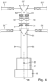
- FIG. 3 shows schematically an image recording device according to the invention.
- a camera 50 with a lens 51 is provided.
- the camera 50 can also comprise the lens 51.
- two images are recorded simultaneously. These are the end faces or end sides of a cigarette 52, namely the end face or end side of the mouthpiece, i.e. an end face or end side of a filter 54, and the head end 53 or the head side of the Tobacco stick.
- the cigarette 52 is usually checked during the transverse axial transport on a drum in a receptacle.
- the beam path 61 extends from the head end 53 of the cigarette 52 over a second prism 56, which is displaceable along the longitudinal axis of the cigarette, i.e., in the displacement direction 65, i.e., transversely to the conveying direction of the cigarettes, is reflected twice, and then reflected again by the first prism 55 to be directed toward the lens 51 and the camera 50. Accordingly, a beam path 62 is provided, which is reflected from the end face of the filter 54 to a second prism 56', from there to the first prism 55, and reaches the camera 50.
- both end faces or end sides of the cigarette 52 can be recorded simultaneously with the camera 50.
- Figure 3 shows the optical axis 86 of the camera 50 with the lens 51.
- the lens 51 has a corresponding lens system that defines an optical center 87. From this optical center, the object distance of the lens 51 and also the focal length are defined. This means that the focal length is preferably from the photosensitive chip of the camera to the optical center 87 and the object distance from the object to be imaged or the real image to the optical center 87.
- the second prism 56 When changing the format of the cigarette, especially when the length of the cigarette changes, only the second prism 56 needs to be moved to compensate for different lengths, so that the object distance, ie the optical distance of the respective end face to the lens 51 of the camera 50, is the same. In this way, even with a shallow depth of field of 1 to 2 mm, both end faces can be sharply imaged.
- a mirror-symmetrical structure may also be desired, in which, when the cigarette length increases, the end face of the filter shifts to the left just as far as the head end face 53 shifts to the right.
- the second prism 56' should also be designed to be displaceable in the longitudinal axial direction of the cigarette in order to enable the respective end face to be focused.
- Figure 4 shows a schematic representation of another embodiment of an image recording device not belonging to the invention.
- four images are recorded simultaneously by the camera 50. Images of the end faces of the filters of filter cigarettes 52, 52', 52", 52''' are to be recorded. Beam paths 61 to 64 of different lengths are also shown. Here, the path length of beam paths 61 and 63 is longer than the path length of beam paths 62 and 64.
- corresponding lenses 70 and 70' are provided, which produce an intermediate image, namely a real intermediate image, of the end faces of filter cigarettes 52' and 52" at 71 and 71'.
- the path length of the intermediate images 71 and 71' to the camera or to the lens 51 of camera 50 is then exactly the same length as the path length of the second beam path 62 and the fourth beam path 64. In this way, four sharp images can be imaged simultaneously on camera 50.
- corresponding rays run to the first prism 55' via the lenses 70, 70' to form corresponding real intermediate images 71, 71', and further above or below the first prism 55 to the camera 50 with the lens 51.
- the rays from the end faces of the filter cigarettes 52 and 52''' run from the end faces to the first prism 55 and are reflected there to the camera 50 with the lens 51.
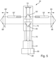
- Figure 5 shows a further embodiment of an image recording device 44 according to the invention.
- second prisms 56 and 56' are provided as path length adjustment devices, which are displaceable in the displacement direction 65 and 65' respectively.
- the displacement direction is also longitudinally axial with the longitudinal axes of the cigarettes 52 and 52'''.
- first Prism 55' reflects the beams to a mirror device 72 and from there further reflects them toward the camera 50 with the lens 51.
- the mirror device 72 is designed such that the beams reflected by the mirror device 72 to the lens 51 of the camera 50 are guided above or below the first prisms 55 and 55'.
- an encapsulation of part of the beam path in the form of covers 75 and 75' is schematically indicated. This prevents any influence of impurities in the air on the respective images.
- Figure 6 shows a schematic representation of another embodiment of an image recording device according to the invention.
- only the end faces of the filters of the respective cigarettes 52 to 52''' are recorded.
- the rays coming from the end faces of the filters of the cigarettes 52 and 52''' are lengthened in their beam path.
- the distances of the prisms 56 and 56' from the prism 55" and 55''' are preferably adjustable. These can, for example, be moved perpendicular to the optical axis of the lens 51 or, accordingly, parallel to the longitudinal axes of the cigarettes 52 to 52''' or the receiving troughs of a transport drum or test drum (not shown).
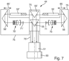
- Figure 7 shows a further embodiment of an inventive Image recording device. Compared to Figure 5 is used in the embodiment according to Figure 7 The object distance of the images for the end faces of the filters of the cigarettes 52 and 52' is not extended via a mirror device 72, but instead the object distance of the end faces of the head ends is shortened to the object distance of the images of the end faces of the filters via lenses 70 and 70' and generated real intermediate images 71 and 71'. This has the advantage that fewer interfering particles can be present on the path or in the beam paths of the image recording device according to the invention, so that the image recordings are improved for this reason alone.
- Additional cladding or barriers can also be installed to prevent foreign objects from entering the optical path.
- images of the surface or end faces of cigarettes or filters are captured by appropriate cameras or camera systems and analyzed in an evaluation unit. For example, it can be analyzed whether the captured images conform to specifications.
- images of the same objects taken one after the other can be used to calculate artifacts or contamination that may occur in the optical path.
- the optical systems are used on a production machine in the tobacco processing industry, particularly where space is limited.
- appropriate reflective optical devices are used that are compact and reflect the images away from the confined space toward a camera with a lens.
- Optical measurements are intended to determine properties such as contamination or partial destruction of the objects. They can also determine precise length and area measurements.
- the image acquisition device is modular and cost-effective and can be integrated into various measurement locations and different machine types. Furthermore, a variable or flexible beam path for optical inspection is possible to accommodate different conveyor drum arrangements.
- path length adjustment devices in the form of one or more second reflective optical devices or in the form of a lens by means of which a real intermediate imaging is possible, a product length-independent construction of the camera with the lens can also be provided.
- a bidirectional beam path is preferably provided to provide the possibility of integrated illumination.
- an illumination device can be provided in the region of the camera, for example, which emits light in the direction of the first reflective optical device.
- the invention It is also possible to reduce the number of cameras and lenses. This also means that fewer industrial computers are needed to perform a variety of optical examinations.
- the optical paths are almost completely encapsulated, for example, by providing tubes to keep air contaminants away from the optical paths. Airtight tubes can also be provided that are pressurized to further reduce image degradation.
Landscapes
- Health & Medical Sciences (AREA)
- General Health & Medical Sciences (AREA)
- Toxicology (AREA)
- Physics & Mathematics (AREA)
- Life Sciences & Earth Sciences (AREA)
- Chemical & Material Sciences (AREA)
- Analytical Chemistry (AREA)
- Biochemistry (AREA)
- General Physics & Mathematics (AREA)
- Immunology (AREA)
- Pathology (AREA)
- Manufacturing Of Cigar And Cigarette Tobacco (AREA)
Priority Applications (1)
| Application Number | Priority Date | Filing Date | Title |
|---|---|---|---|
| PL15154819.5T PL2918180T5 (pl) | 2014-02-21 | 2015-02-12 | Optyczna kontrola wyrobów sztabkowych przemysłu tytoniowego |
Applications Claiming Priority (1)
| Application Number | Priority Date | Filing Date | Title |
|---|---|---|---|
| DE102014203158.3A DE102014203158B4 (de) | 2014-02-21 | 2014-02-21 | Optische Prüfung von stabförmigen Artikeln der Tabak verarbeitenden Industrie |
Publications (3)
| Publication Number | Publication Date |
|---|---|
| EP2918180A1 EP2918180A1 (de) | 2015-09-16 |
| EP2918180B1 EP2918180B1 (de) | 2018-04-04 |
| EP2918180B2 true EP2918180B2 (de) | 2025-04-30 |
Family
ID=52469663
Family Applications (1)
| Application Number | Title | Priority Date | Filing Date |
|---|---|---|---|
| EP15154819.5A Active EP2918180B2 (de) | 2014-02-21 | 2015-02-12 | Optische Prüfung von stabförmigen Artikeln der Tabak verarbeitenden Industrie |
Country Status (4)
| Country | Link |
|---|---|
| EP (1) | EP2918180B2 (pl) |
| CN (1) | CN104856220B (pl) |
| DE (1) | DE102014203158B4 (pl) |
| PL (1) | PL2918180T5 (pl) |
Families Citing this family (12)
| Publication number | Priority date | Publication date | Assignee | Title |
|---|---|---|---|---|
| US10401148B2 (en) * | 2015-12-21 | 2019-09-03 | Philip Morris Products S.A. | Apparatus and method for acquiring data relative to a dimension of an elongated object |
| DE102016107247A1 (de) * | 2016-04-19 | 2017-10-19 | Hauni Maschinenbau Gmbh | Anordnung und Verfahren zum optischen Prüfen von stabförmigen Artikeln der Tabak verarbeitenden Industrie |
| DE102016013719A1 (de) * | 2016-11-17 | 2018-05-17 | Focke & Co. (Gmbh & Co. Kg) | Vorrichtung und Verfahren zur optischen Prüfung von bei der Verpackung von Produkten zu prüfenden Objekten |
| IT201800002250A1 (it) * | 2018-01-31 | 2019-07-31 | Gd Spa | Metodo e apparato per l’ispezione delle estremità di spezzoni a forma di barretta dell’industria del tabacco |
| CN110200315B (zh) * | 2018-12-11 | 2021-08-20 | 费锦东 | 一种用于烟支外观视觉检测机器的成像装置 |
| PL3714707T3 (pl) | 2019-03-29 | 2023-02-06 | International Tobacco Machinery Poland Spółka Z Ograniczoną Odpowiedzialnością | Układ pomiarowy do kontroli jakości rurki i sposób kontrolowania jakości rurki |
| CN110663995A (zh) * | 2019-09-26 | 2020-01-10 | 云南远足科技有限公司 | 一种加热不燃烧烟支在线质量检测设备和方法及生产设备 |
| CN110579484A (zh) * | 2019-09-26 | 2019-12-17 | 阚晖 | 一种多元复合卷制产品的质量检测设备及其方法 |
| PL438470A1 (pl) * | 2021-07-14 | 2023-01-16 | International Tobacco Machinery Poland Spółka Z Ograniczoną Odpowiedzialnością | Urządzenie do wytwarzania i sposób wytwarzania wielosegmentowych artykułów prętopodobnych |
| IT202100023942A1 (it) * | 2021-09-17 | 2023-03-17 | Gd Spa | Metodo e sistema per ispezionare articoli da fumo |
| IT202100023954A1 (it) * | 2021-09-17 | 2023-03-17 | Gd Spa | Apparato assemblatore e metodo di assemblaggio per produrre articoli da fumo multicomponente. |
| DE102022112419A1 (de) * | 2022-05-18 | 2023-11-23 | Körber Technologies Gmbh | Anordnung zum queraxialen Fördern von stabförmigen Artikeln der Tabak verarbeitenden Industrie |
Citations (3)
| Publication number | Priority date | Publication date | Assignee | Title |
|---|---|---|---|---|
| EP0570163A2 (en) † | 1992-05-15 | 1993-11-18 | Philip Morris Products Inc. | Systems for optically inspecting cylindrical surfaces |
| EP0937978A1 (en) † | 1998-02-23 | 1999-08-25 | G.D S.p.A. | An electro-optical unit for scanning the entire lateral surface of articles substantially cylindrical in shape |
| US20050185181A1 (en) † | 2003-03-07 | 2005-08-25 | Ismeca Semiconductor Holding Sa | Optical device and inspection module |
Family Cites Families (14)
| Publication number | Priority date | Publication date | Assignee | Title |
|---|---|---|---|---|
| US4616139A (en) | 1983-05-31 | 1986-10-07 | Hauni-Werke Korber & Co. Kg. | Apparatus for optical scanning of the exterior of a moving cigarette rod or the like |
| IT1234506B (it) * | 1988-05-31 | 1992-05-19 | Gd Spa | Metodo per il controllo elettro-ottico di sigarette |
| IT1229428B (it) * | 1988-06-11 | 1991-08-08 | Hauni Werke Koerber & Co Kg | Dispositivo di taglio. |
| US5448365A (en) | 1992-05-15 | 1995-09-05 | Philip Morris Incorporated | Systems for optical inspection |
| DE4302698B4 (de) * | 1993-02-01 | 2007-09-27 | Sms Demag Ag | Verfahren und Vorrichtung zum Führen eines Stahlbandes während seines Durchlaufs durch eine kontinuierliche Behandlungsanlage |
| IT1285935B1 (it) * | 1996-06-10 | 1998-06-26 | Gd Spa | Metodo e dispositivo per il controllo dell'integrita' esteriore di sigarette |
| CN1216555C (zh) * | 2001-09-25 | 2005-08-31 | 日本烟草产业株式会社 | 检查棒状物品外观的装置 |
| DE10245559A1 (de) * | 2002-09-30 | 2004-04-08 | Carl Zeiss Jena Gmbh | Kamera |
| GB0306468D0 (en) * | 2003-03-20 | 2003-04-23 | Molins Plc | A method and apparatus for determining one or more physical properties of a rolled smoking article or filter rod |
| CN2698097Y (zh) * | 2004-05-12 | 2005-05-11 | 上海恒尚自动化设备有限公司 | 用于烟草行业的圆周在线光学投影检测机构 |
| DE102004040912A1 (de) * | 2004-08-23 | 2006-03-09 | Hauni Maschinenbau Ag | Optische Kontrolle von Produkten der Tabakverarbeitenden Industrie |
| DE102006009482A1 (de) * | 2006-02-27 | 2007-09-06 | Hauni Maschinenbau Ag | Optische Kontrolle von Produkten der Tabak verarbeitenden Industrie |
| AT504163B1 (de) | 2006-05-16 | 2008-10-15 | Profactor Res And Solutions Gm | Anordnung und vorsatz zur prüfung von gegenständen |
| CN103389313B (zh) | 2012-05-11 | 2015-12-16 | 珠海格力电器股份有限公司 | 光学检测结构 |
-
2014
- 2014-02-21 DE DE102014203158.3A patent/DE102014203158B4/de active Active
-
2015
- 2015-02-12 PL PL15154819.5T patent/PL2918180T5/pl unknown
- 2015-02-12 EP EP15154819.5A patent/EP2918180B2/de active Active
- 2015-02-25 CN CN201510087316.3A patent/CN104856220B/zh active Active
Patent Citations (3)
| Publication number | Priority date | Publication date | Assignee | Title |
|---|---|---|---|---|
| EP0570163A2 (en) † | 1992-05-15 | 1993-11-18 | Philip Morris Products Inc. | Systems for optically inspecting cylindrical surfaces |
| EP0937978A1 (en) † | 1998-02-23 | 1999-08-25 | G.D S.p.A. | An electro-optical unit for scanning the entire lateral surface of articles substantially cylindrical in shape |
| US20050185181A1 (en) † | 2003-03-07 | 2005-08-25 | Ismeca Semiconductor Holding Sa | Optical device and inspection module |
Also Published As
| Publication number | Publication date |
|---|---|
| PL2918180T3 (pl) | 2018-09-28 |
| DE102014203158B4 (de) | 2016-01-14 |
| DE102014203158A1 (de) | 2015-08-27 |
| PL2918180T5 (pl) | 2025-08-18 |
| CN104856220A (zh) | 2015-08-26 |
| CN104856220B (zh) | 2019-02-01 |
| EP2918180B1 (de) | 2018-04-04 |
| EP2918180A1 (de) | 2015-09-16 |
Similar Documents
| Publication | Publication Date | Title |
|---|---|---|
| EP2918180B2 (de) | Optische Prüfung von stabförmigen Artikeln der Tabak verarbeitenden Industrie | |
| EP1463421B1 (de) | Einrichtung und system zum messen von eigenschaften von multisegmentfiltern sowie verfahren hierzu | |
| EP2677273B1 (de) | Messvorrichtung und Verfahren zur optischen Prüfung einer Stirnfläche eines queraxial geförderten stabförmigen Produkts der Tabak verarbeitenden Industrie | |
| EP1397961B1 (de) | Verfahren und Vorrichtung zum Messen der Länge und des Durchmessers von Filterstäben | |
| EP2022347B1 (de) | Optische Kontrolle von Produkten der Tabak verarbeitenden Industrie | |
| EP1826557B2 (de) | Optische Kontrolle von Produkten der Tabak verarbeitenden Industrie | |
| EP2679950B1 (de) | Vorrichtung und Verfahren zur Bewertung einer Stirnfläche eines stabförmigen Produkts der Tabak verarbeitenden Industrie | |
| DE102012200611A1 (de) | Prüfen von stabförmigen Artikeln der Tabak verarbeitenden Industrie | |
| DE102004040912A1 (de) | Optische Kontrolle von Produkten der Tabakverarbeitenden Industrie | |
| DE102009014018A1 (de) | Prüfung von stabförmigen Artikeln der Tabak verarbeitenden Industrie | |
| EP3510877B1 (de) | Vorrichtung und verfahren zum prüfen von stabförmigen artikeln der tabak verarbeitenden industrie | |
| EP1479303B1 (de) | Vorrichtung zum Messen des Durchmessers eines stabförmigen Gegenstandes insbesondere der Tabak verarbeitenden Industrie | |
| EP4106557A1 (de) | Verfahren und vorrichtung zur prüfung von stabförmigen produkten der zigarettenindustrie | |
| DE102014209000A1 (de) | Optische Prüfung von stabförmigen Artikeln der Tabak verarbeitenden Industrie | |
| EP1647800A1 (de) | Vorrichtung und Verfahren zum Messen des Durchmessers eines stabförmigen Gegenstandes insbesondere der Tabak verarbeitenden Industrie | |
| EP3587998A1 (de) | Vorrichtung und verfahren zur optischen messung an einem produktstrang der tabak verarbeitenden industrie und verwendung einer optischen messvorrichtung | |
| EP3085253B1 (de) | Strangmaschine der tabak verarbeitenden industrie und verfahren zum herstellen von multisegmentstäben | |
| EP1782703B1 (de) | Vorrichtung zur optischen Überwachung eines Materialstranges der tabakverarbeitenden Industrie | |
| DE3420470A1 (de) | Optische pruefvorrichtung fuer zigaretten | |
| WO2017182362A1 (de) | Anordnung und verfahren zum optischen prüfen von stabförmigen artikeln der tabak verarbeitenden industrie | |
| EP3552501B1 (de) | Vorrichtung und verfahren zur inspektion einer stirnfläche eines stabförmigen rauchartikels | |
| DE102018129256A1 (de) | Vorrichtung und Verfahren zur optischen Messung an einem Produktstrang der Tabak verarbeitenden Industrie und Verwendung einer optischen Messvorrichtung | |
| DE19514718A1 (de) | Verfahren zur Vermessung von gekrümmten Oberflächen |
Legal Events
| Date | Code | Title | Description |
|---|---|---|---|
| PUAI | Public reference made under article 153(3) epc to a published international application that has entered the european phase |
Free format text: ORIGINAL CODE: 0009012 |
|
| AK | Designated contracting states |
Kind code of ref document: A1 Designated state(s): AL AT BE BG CH CY CZ DE DK EE ES FI FR GB GR HR HU IE IS IT LI LT LU LV MC MK MT NL NO PL PT RO RS SE SI SK SM TR |
|
| AX | Request for extension of the european patent |
Extension state: BA ME |
|
| 17P | Request for examination filed |
Effective date: 20160307 |
|
| RBV | Designated contracting states (corrected) |
Designated state(s): AL AT BE BG CH CY CZ DE DK EE ES FI FR GB GR HR HU IE IS IT LI LT LU LV MC MK MT NL NO PL PT RO RS SE SI SK SM TR |
|
| RAP1 | Party data changed (applicant data changed or rights of an application transferred) |
Owner name: HAUNI MASCHINENBAU GMBH |
|
| TPAC | Observations filed by third parties |
Free format text: ORIGINAL CODE: EPIDOSNTIPA |
|
| STAA | Information on the status of an ep patent application or granted ep patent |
Free format text: STATUS: EXAMINATION IS IN PROGRESS |
|
| 17Q | First examination report despatched |
Effective date: 20170310 |
|
| GRAP | Despatch of communication of intention to grant a patent |
Free format text: ORIGINAL CODE: EPIDOSNIGR1 |
|
| STAA | Information on the status of an ep patent application or granted ep patent |
Free format text: STATUS: GRANT OF PATENT IS INTENDED |
|
| INTG | Intention to grant announced |
Effective date: 20171031 |
|
| GRAS | Grant fee paid |
Free format text: ORIGINAL CODE: EPIDOSNIGR3 |
|
| GRAA | (expected) grant |
Free format text: ORIGINAL CODE: 0009210 |
|
| STAA | Information on the status of an ep patent application or granted ep patent |
Free format text: STATUS: THE PATENT HAS BEEN GRANTED |
|
| AK | Designated contracting states |
Kind code of ref document: B1 Designated state(s): AL AT BE BG CH CY CZ DE DK EE ES FI FR GB GR HR HU IE IS IT LI LT LU LV MC MK MT NL NO PL PT RO RS SE SI SK SM TR |
|
| REG | Reference to a national code |
Ref country code: GB Ref legal event code: FG4D Free format text: NOT ENGLISH |
|
| REG | Reference to a national code |
Ref country code: CH Ref legal event code: EP |
|
| REG | Reference to a national code |
Ref country code: AT Ref legal event code: REF Ref document number: 984590 Country of ref document: AT Kind code of ref document: T Effective date: 20180415 |
|
| REG | Reference to a national code |
Ref country code: IE Ref legal event code: FG4D Free format text: LANGUAGE OF EP DOCUMENT: GERMAN |
|
| REG | Reference to a national code |
Ref country code: DE Ref legal event code: R096 Ref document number: 502015003674 Country of ref document: DE |
|
| REG | Reference to a national code |
Ref country code: NL Ref legal event code: FP |
|
| REG | Reference to a national code |
Ref country code: LT Ref legal event code: MG4D |
|
| PG25 | Lapsed in a contracting state [announced via postgrant information from national office to epo] |
Ref country code: ES Free format text: LAPSE BECAUSE OF FAILURE TO SUBMIT A TRANSLATION OF THE DESCRIPTION OR TO PAY THE FEE WITHIN THE PRESCRIBED TIME-LIMIT Effective date: 20180404 Ref country code: LT Free format text: LAPSE BECAUSE OF FAILURE TO SUBMIT A TRANSLATION OF THE DESCRIPTION OR TO PAY THE FEE WITHIN THE PRESCRIBED TIME-LIMIT Effective date: 20180404 Ref country code: BG Free format text: LAPSE BECAUSE OF FAILURE TO SUBMIT A TRANSLATION OF THE DESCRIPTION OR TO PAY THE FEE WITHIN THE PRESCRIBED TIME-LIMIT Effective date: 20180704 Ref country code: FI Free format text: LAPSE BECAUSE OF FAILURE TO SUBMIT A TRANSLATION OF THE DESCRIPTION OR TO PAY THE FEE WITHIN THE PRESCRIBED TIME-LIMIT Effective date: 20180404 Ref country code: NO Free format text: LAPSE BECAUSE OF FAILURE TO SUBMIT A TRANSLATION OF THE DESCRIPTION OR TO PAY THE FEE WITHIN THE PRESCRIBED TIME-LIMIT Effective date: 20180704 Ref country code: SE Free format text: LAPSE BECAUSE OF FAILURE TO SUBMIT A TRANSLATION OF THE DESCRIPTION OR TO PAY THE FEE WITHIN THE PRESCRIBED TIME-LIMIT Effective date: 20180404 Ref country code: AL Free format text: LAPSE BECAUSE OF FAILURE TO SUBMIT A TRANSLATION OF THE DESCRIPTION OR TO PAY THE FEE WITHIN THE PRESCRIBED TIME-LIMIT Effective date: 20180404 |
|
| PG25 | Lapsed in a contracting state [announced via postgrant information from national office to epo] |
Ref country code: GR Free format text: LAPSE BECAUSE OF FAILURE TO SUBMIT A TRANSLATION OF THE DESCRIPTION OR TO PAY THE FEE WITHIN THE PRESCRIBED TIME-LIMIT Effective date: 20180705 Ref country code: HR Free format text: LAPSE BECAUSE OF FAILURE TO SUBMIT A TRANSLATION OF THE DESCRIPTION OR TO PAY THE FEE WITHIN THE PRESCRIBED TIME-LIMIT Effective date: 20180404 Ref country code: LV Free format text: LAPSE BECAUSE OF FAILURE TO SUBMIT A TRANSLATION OF THE DESCRIPTION OR TO PAY THE FEE WITHIN THE PRESCRIBED TIME-LIMIT Effective date: 20180404 Ref country code: RS Free format text: LAPSE BECAUSE OF FAILURE TO SUBMIT A TRANSLATION OF THE DESCRIPTION OR TO PAY THE FEE WITHIN THE PRESCRIBED TIME-LIMIT Effective date: 20180404 |
|
| PG25 | Lapsed in a contracting state [announced via postgrant information from national office to epo] |
Ref country code: PT Free format text: LAPSE BECAUSE OF FAILURE TO SUBMIT A TRANSLATION OF THE DESCRIPTION OR TO PAY THE FEE WITHIN THE PRESCRIBED TIME-LIMIT Effective date: 20180806 |
|
| REG | Reference to a national code |
Ref country code: DE Ref legal event code: R026 Ref document number: 502015003674 Country of ref document: DE |
|
| PLBI | Opposition filed |
Free format text: ORIGINAL CODE: 0009260 |
|
| PLAX | Notice of opposition and request to file observation + time limit sent |
Free format text: ORIGINAL CODE: EPIDOSNOBS2 |
|
| PG25 | Lapsed in a contracting state [announced via postgrant information from national office to epo] |
Ref country code: RO Free format text: LAPSE BECAUSE OF FAILURE TO SUBMIT A TRANSLATION OF THE DESCRIPTION OR TO PAY THE FEE WITHIN THE PRESCRIBED TIME-LIMIT Effective date: 20180404 Ref country code: SK Free format text: LAPSE BECAUSE OF FAILURE TO SUBMIT A TRANSLATION OF THE DESCRIPTION OR TO PAY THE FEE WITHIN THE PRESCRIBED TIME-LIMIT Effective date: 20180404 Ref country code: CZ Free format text: LAPSE BECAUSE OF FAILURE TO SUBMIT A TRANSLATION OF THE DESCRIPTION OR TO PAY THE FEE WITHIN THE PRESCRIBED TIME-LIMIT Effective date: 20180404 Ref country code: DK Free format text: LAPSE BECAUSE OF FAILURE TO SUBMIT A TRANSLATION OF THE DESCRIPTION OR TO PAY THE FEE WITHIN THE PRESCRIBED TIME-LIMIT Effective date: 20180404 Ref country code: EE Free format text: LAPSE BECAUSE OF FAILURE TO SUBMIT A TRANSLATION OF THE DESCRIPTION OR TO PAY THE FEE WITHIN THE PRESCRIBED TIME-LIMIT Effective date: 20180404 |
|
| 26 | Opposition filed |
Opponent name: G.D SOCIETA PER AZIONI Effective date: 20190102 |
|
| PG25 | Lapsed in a contracting state [announced via postgrant information from national office to epo] |
Ref country code: SM Free format text: LAPSE BECAUSE OF FAILURE TO SUBMIT A TRANSLATION OF THE DESCRIPTION OR TO PAY THE FEE WITHIN THE PRESCRIBED TIME-LIMIT Effective date: 20180404 |
|
| PLBB | Reply of patent proprietor to notice(s) of opposition received |
Free format text: ORIGINAL CODE: EPIDOSNOBS3 |
|
| PG25 | Lapsed in a contracting state [announced via postgrant information from national office to epo] |
Ref country code: SI Free format text: LAPSE BECAUSE OF FAILURE TO SUBMIT A TRANSLATION OF THE DESCRIPTION OR TO PAY THE FEE WITHIN THE PRESCRIBED TIME-LIMIT Effective date: 20180404 |
|
| REG | Reference to a national code |
Ref country code: CH Ref legal event code: PL |
|
| PG25 | Lapsed in a contracting state [announced via postgrant information from national office to epo] |
Ref country code: MC Free format text: LAPSE BECAUSE OF FAILURE TO SUBMIT A TRANSLATION OF THE DESCRIPTION OR TO PAY THE FEE WITHIN THE PRESCRIBED TIME-LIMIT Effective date: 20180404 Ref country code: LU Free format text: LAPSE BECAUSE OF NON-PAYMENT OF DUE FEES Effective date: 20190212 |
|
| REG | Reference to a national code |
Ref country code: BE Ref legal event code: MM Effective date: 20190228 |
|
| REG | Reference to a national code |
Ref country code: IE Ref legal event code: MM4A |
|
| PG25 | Lapsed in a contracting state [announced via postgrant information from national office to epo] |
Ref country code: CH Free format text: LAPSE BECAUSE OF NON-PAYMENT OF DUE FEES Effective date: 20190228 Ref country code: LI Free format text: LAPSE BECAUSE OF NON-PAYMENT OF DUE FEES Effective date: 20190228 |
|
| PG25 | Lapsed in a contracting state [announced via postgrant information from national office to epo] |
Ref country code: IE Free format text: LAPSE BECAUSE OF NON-PAYMENT OF DUE FEES Effective date: 20190212 |
|
| PG25 | Lapsed in a contracting state [announced via postgrant information from national office to epo] |
Ref country code: FR Free format text: LAPSE BECAUSE OF NON-PAYMENT OF DUE FEES Effective date: 20190228 Ref country code: BE Free format text: LAPSE BECAUSE OF NON-PAYMENT OF DUE FEES Effective date: 20190228 |
|
| PG25 | Lapsed in a contracting state [announced via postgrant information from national office to epo] |
Ref country code: TR Free format text: LAPSE BECAUSE OF FAILURE TO SUBMIT A TRANSLATION OF THE DESCRIPTION OR TO PAY THE FEE WITHIN THE PRESCRIBED TIME-LIMIT Effective date: 20180404 |
|
| PG25 | Lapsed in a contracting state [announced via postgrant information from national office to epo] |
Ref country code: MT Free format text: LAPSE BECAUSE OF FAILURE TO SUBMIT A TRANSLATION OF THE DESCRIPTION OR TO PAY THE FEE WITHIN THE PRESCRIBED TIME-LIMIT Effective date: 20180404 |
|
| REG | Reference to a national code |
Ref country code: AT Ref legal event code: MM01 Ref document number: 984590 Country of ref document: AT Kind code of ref document: T Effective date: 20200212 |
|
| PG25 | Lapsed in a contracting state [announced via postgrant information from national office to epo] |
Ref country code: AT Free format text: LAPSE BECAUSE OF NON-PAYMENT OF DUE FEES Effective date: 20200212 Ref country code: CY Free format text: LAPSE BECAUSE OF FAILURE TO SUBMIT A TRANSLATION OF THE DESCRIPTION OR TO PAY THE FEE WITHIN THE PRESCRIBED TIME-LIMIT Effective date: 20180404 |
|
| PG25 | Lapsed in a contracting state [announced via postgrant information from national office to epo] |
Ref country code: IS Free format text: LAPSE BECAUSE OF FAILURE TO SUBMIT A TRANSLATION OF THE DESCRIPTION OR TO PAY THE FEE WITHIN THE PRESCRIBED TIME-LIMIT Effective date: 20180804 |
|
| PG25 | Lapsed in a contracting state [announced via postgrant information from national office to epo] |
Ref country code: HU Free format text: LAPSE BECAUSE OF FAILURE TO SUBMIT A TRANSLATION OF THE DESCRIPTION OR TO PAY THE FEE WITHIN THE PRESCRIBED TIME-LIMIT; INVALID AB INITIO Effective date: 20150212 |
|
| APBM | Appeal reference recorded |
Free format text: ORIGINAL CODE: EPIDOSNREFNO |
|
| APBP | Date of receipt of notice of appeal recorded |
Free format text: ORIGINAL CODE: EPIDOSNNOA2O |
|
| APAH | Appeal reference modified |
Free format text: ORIGINAL CODE: EPIDOSCREFNO |
|
| APBQ | Date of receipt of statement of grounds of appeal recorded |
Free format text: ORIGINAL CODE: EPIDOSNNOA3O |
|
| PG25 | Lapsed in a contracting state [announced via postgrant information from national office to epo] |
Ref country code: MK Free format text: LAPSE BECAUSE OF FAILURE TO SUBMIT A TRANSLATION OF THE DESCRIPTION OR TO PAY THE FEE WITHIN THE PRESCRIBED TIME-LIMIT Effective date: 20180404 |
|
| REG | Reference to a national code |
Ref country code: DE Ref legal event code: R081 Ref document number: 502015003674 Country of ref document: DE Owner name: KOERBER TECHNOLOGIES GMBH, DE Free format text: FORMER OWNER: HAUNI MASCHINENBAU GMBH, 21033 HAMBURG, DE |
|
| REG | Reference to a national code |
Ref country code: NL Ref legal event code: HC Owner name: KOERBER TECHNOLOGIES GMBH; DE Free format text: DETAILS ASSIGNMENT: CHANGE OF OWNER(S), CHANGE OF OWNER(S) NAME; FORMER OWNER NAME: HAUNI MASCHINENBAU GMBH Effective date: 20221025 |
|
| RAP4 | Party data changed (patent owner data changed or rights of a patent transferred) |
Owner name: KOERBER TECHNOLOGIES GMBH |
|
| P01 | Opt-out of the competence of the unified patent court (upc) registered |
Effective date: 20230616 |
|
| PLAB | Opposition data, opponent's data or that of the opponent's representative modified |
Free format text: ORIGINAL CODE: 0009299OPPO |
|
| R26 | Opposition filed (corrected) |
Opponent name: G.D SOCIETA PER AZIONI Effective date: 20190102 |
|
| APBU | Appeal procedure closed |
Free format text: ORIGINAL CODE: EPIDOSNNOA9O |
|
| PGFP | Annual fee paid to national office [announced via postgrant information from national office to epo] |
Ref country code: NL Payment date: 20250224 Year of fee payment: 11 |
|
| PUAH | Patent maintained in amended form |
Free format text: ORIGINAL CODE: 0009272 |
|
| STAA | Information on the status of an ep patent application or granted ep patent |
Free format text: STATUS: PATENT MAINTAINED AS AMENDED |
|
| PGFP | Annual fee paid to national office [announced via postgrant information from national office to epo] |
Ref country code: DE Payment date: 20250225 Year of fee payment: 11 |
|
| PGFP | Annual fee paid to national office [announced via postgrant information from national office to epo] |
Ref country code: PL Payment date: 20250127 Year of fee payment: 11 |
|
| PGFP | Annual fee paid to national office [announced via postgrant information from national office to epo] |
Ref country code: IT Payment date: 20250226 Year of fee payment: 11 Ref country code: GB Payment date: 20250221 Year of fee payment: 11 |
|
| 27A | Patent maintained in amended form |
Effective date: 20250430 |
|
| AK | Designated contracting states |
Kind code of ref document: B2 Designated state(s): AL AT BE BG CH CY CZ DE DK EE ES FI FR GB GR HR HU IE IS IT LI LT LU LV MC MK MT NL NO PL PT RO RS SE SI SK SM TR |
|
| REG | Reference to a national code |
Ref country code: DE Ref legal event code: R102 Ref document number: 502015003674 Country of ref document: DE |
|
| REG | Reference to a national code |
Ref country code: NL Ref legal event code: FP |