EP2917724B1 - Test strip ejector for medical device - Google Patents
Test strip ejector for medical device Download PDFInfo
- Publication number
- EP2917724B1 EP2917724B1 EP13788973.9A EP13788973A EP2917724B1 EP 2917724 B1 EP2917724 B1 EP 2917724B1 EP 13788973 A EP13788973 A EP 13788973A EP 2917724 B1 EP2917724 B1 EP 2917724B1
- Authority
- EP
- European Patent Office
- Prior art keywords
- test strip
- ejection
- test
- sled
- armature
- Prior art date
- Legal status (The legal status is an assumption and is not a legal conclusion. Google has not performed a legal analysis and makes no representation as to the accuracy of the status listed.)
- Active
Links
Images










Classifications
-
- G—PHYSICS
- G01—MEASURING; TESTING
- G01N—INVESTIGATING OR ANALYSING MATERIALS BY DETERMINING THEIR CHEMICAL OR PHYSICAL PROPERTIES
- G01N33/00—Investigating or analysing materials by specific methods not covered by groups G01N1/00 - G01N31/00
- G01N33/48—Biological material, e.g. blood, urine; Haemocytometers
- G01N33/483—Physical analysis of biological material
- G01N33/487—Physical analysis of biological material of liquid biological material
- G01N33/4875—Details of handling test elements, e.g. dispensing or storage, not specific to a particular test method
Definitions
- a blood glucose meter is used as a diagnostic device to measure blood glucose levels of patients suffering from diabetes.
- Blood glucose meters use a test strip that receives a blood sample of the patient.
- the test strip has electrical contacts on the strip that are electrically contacted when the test strip is inserted into the meter.
- the meter determines a blood glucose level by measuring currents passed through the electrical contacts of the strip, and provides for readout of the glucose level.
- Known meters receive the test strip in an insertion direction that also engages the electrical strip conductors of the test strip with the electrical contacts of the meter.
- the insertion motion is used to drive the electrical contacts of the test strip into engagement with the contacts of the meter.
- the strip ejection system permits ejection of the dosed test strip following testing without further contact of the test strip by the user. Any interference with or sliding contact of the electrical contacts of the test strip during insertion, however, can damage the electrical contacts or misalign one or more of the contacts.
- a force applied to eject the test strip of known strip ejection systems can also cause racking or rotation of the test strip which can bind the test strip or interfere with ejection.
- the measurement device of U.S. Published Patent Application No. 2010/0012530 to Watanabe et al. includes a pushing member 11 having projection part 11b that is slidably guided within a pushing member cover 12. Clearance between the projection part 11b and pushing member 12 therefore limits the control available to reduce deflection of pushing member 11 during its travel to displace a sensor 200.
- pushing member 11 includes a single substantially centrally positioned projection part 11a guided in a notch 10a. Control of racking of the pushing member 11 during travel is limited by the tolerances between the projection part 11b and pushing member cover 12, and between the projection part 11a and notch 10a.
- European Patent Application EP 1321769 to Pugh appears to disclose a test strip dispensing system having strip push members 116, 210 guided between rails 100 or 214. Rails of this design are positioned external to the strip push members.
- the strip push members include outer wall areas such as ledges 220 acting as guides. Ledges 220, however, are positioned within the rails 214, therefore continuous positive contact between the strip push members 116, 210 and the rails to limit racking is not provided and racking can occur due to a tolerance between the components.
- the design of strip push members 116, 210 and rails 100, 214 also precludes installation in a direction perpendicular to the push member travel direction.
- the present invention is directed to the subject-matter of the claims attached, in particular to the test strip ejector system according to claim 1 for receiving and ejecting a test strip of a fluid testing medical device, to the glucose test meter according to claim 12 having a test strip ejector system according to any of claims 1 to 11, and to the method according to claim 15 for receiving and ejecting a test strip by the test strip ejector system according to any of claims 1 to 11.
- the mechanism assembly includes a power source and an electric motor connected to the power source.
- the electric motor has an armature displaced when the electric motor is energized.
- a digital display/user interface is provided. Selection of an ejection function presented on the digital display/user interface initiates operation of the electric motor and displacement of the armature thereby displacing the test strip in the ejection direction.
- An operating system including a microprocessor is connected to the display/user interface. The microprocessor controls direction of operation and operating speed of the motor.
- the operating system includes an accelerometer.
- the microprocessor controls direction of operation and operating speed of the motor.
- the accelerometer acts when an orientation of the fluid testing medical device is changed to initiate operation of the motor.
- a method for receiving and ejecting a test strip by a mechanism assembly of a fluid testing medical device.
- the mechanism assembly includes a power source, an electric motor having an armature, a digital display/user interface and an operating system.
- the method includes: supporting the mechanism assembly by the fluid testing medical device; connecting the electric motor to the power source; manually inserting a test strip into the fluid testing medical device; and selecting an ejection function presented on the digital display/user interface to initiate operation of the electric motor and displacement of the armature thereby displacing the test strip in an ejection direction.
- Circuit board assembly 22 includes a printed circuit board 24 such as a printed circuit board having multiple components attached thereto.
- Housing 12 further includes a mechanism assembly 26 which can be biased prior to or upon receipt of the test strip 18 and can apply a displacement force or a biasing force to eject the test strip 18.
- Mechanism assembly 26 includes ejection button 16 and an axially rotatable mounting pin 28 which is rotatable with respect to a longitudinal pin center axis 30 which is affixed to a stationary component which would be on the PCB, housing, or some other nearby component.
- a member such as an actuator arm 32 is connected to mounting pin 28 and therefore co-rotates as mounting pin 28 axially rotates with respect to longitudinal pin center axis 30.
- the ejection button 16 is biased using an ejection button biasing member 34 to return to the extended position shown following depression by the user.
- Manual depression of ejection button 16 causes mounting pin 28 and therefore actuator arm 32 to rotate, which directly contacts and slidably displaces a sled 36 in the ejection direction "B".
- the sled 36 is slidably and connectably engaged with respect to opposed and parallel oriented first and second guide rails 38, 40.
- First and second guide rails 38, 40 are fixedly connected to printed circuit board 24.
- the actuator arm 32 is shown in a test strip analysis position reached by a counterclockwise rotation with respect to longitudinal pin center axis 30.
- the test strip analysis position can be provided in each of two aspects.
- actuator arm 32 in addition to biasing ejection button 16, actuator arm 32 is also normally biased by ejection button biasing member 34 to the counterclockwise rotated position shown in FIG. 3 , which prepositions the actuator arm 32 and the sled 36 in a neutral position (defined in this aspect as the position shown in FIG. 3 ) ready for receipt of test strip 18.
- test strip 18 is freely manually loaded into housing 12 until a strip end contacts or nearly contacts the sled 36.
- test strip 18 during test strip loading in the second aspect described above, and during the ejection step for both aspects, is in direct contact with each of opposed first and second contact legs 46, 48 which are substantially rigid, integrally connected to sled 36, and positioned between deflectable legs which will be described in reference to FIG. 5 .
- Test strip 18 when positioned within rail cavity 41 directly contacts first and second contact legs 46, 48 which extend from sled 36 into rail cavity 41.
- the sled post 42 has a cylindrical body 54 which is perpendicularly oriented with respect to a planar body portion 56 of sled 36.
- sled 36 is made of a metal such as stainless steel, to maximize a stiffness-to-weight ratio of sled 36.
- Other materials for sled 36 can also be used, including plastics.
- sled post 42 is created of a polymeric material having a low coefficient of friction such as polyoxymethylene (POM).
- a POM material or a similar material having a low coefficient of friction is selected for sled post 42 to maintain the shape of sled post 42 and to minimize frictional resistance between sled post 42 and actuator arm 32 as sled post 42 slides within elongated slot 44 and as actuator arm 32 rotates with respect to sled post 42.
- sled post 42 can be an integral extension of the material of sled 36 and made such as by a staking, drawing or similar process during manufacture of sled 36.
- sled post 42 can be cylindrical, dome shaped, or other shape as the manufacturing process allows.
- PTFE polytetrafluoroethylene
- sled 36 includes proximately positioned first and second legs 58, 60 and oppositely proximately positioned third and fourth legs 62, 64 which are in mirror image configuration with respect to first and second legs 58, 60.
- the sled post 42 according to several aspects is centrally located with respect to each of the first, second, third, and fourth legs 58, 60, 62, 64.
- a fifth leg 66 can also be provided in a spaced apart relationship with respect to first and second legs 58, 60 such that first leg 58, second leg 60, and fifth leg 66 define a first side leg set 67.
- Each of the individual legs 58, 60, 62, 64, 66, 68 have a common geometry, therefore the following discussion of sixth leg 68 applies also to each of the first through fifth legs 58, 60, 62, 64, 66.
- Each of the legs 58, 60, 62, 64, 66, 68 is positioned oppositely about planar body portion 56 with respect to sled post 42 and is therefore oriented downwardly as viewed in FIG. 5 .
- Each of the legs includes an inner concave leg portion 70 directly connected to an engagement portion 72 which is oppositely directed with respect to inner concave leg portion 70.
- sled post 42 includes a post connection end 76 which extends through planar body portion 56 such that post connection end 76 is positioned on a lower body face 78 side of planar body portion 56.
- Post connection end 76 can be mechanically connected to planar body portion 56 using a plurality of connection methods, including staking, forming or adhesively boding, to fix post connection end 76 with respect to planar body portion 56.
- a post retainer 80 can also be included with post connection end 76, which can be biased into contact with planar body portion 56 or displaced, such as by a staking operation, such that post retainer 80 acts as a retention member to further retain the fixed position of post connection end 76.
- an analysis device 130 is modified from analysis device 10 to include a sled 132 having four legs in lieu of six legs, including first, second, third and fourth legs 134, 136, 138, 140 which are substantially equivalent to first, third, fifth and sixth legs 58, 62, 66 and 68 of sled 36.
- the first and second guide rails 38, 40 are removed for clarity.
- the sled post 42 of sled 132 is rotatably connected to actuator arm 32.
- First and second contact legs 142, 144 are similarly provided and oriented on sled 132 and therefore perform the same functions as first and second contact legs 46, 48.
- a mechanism assembly 216 is modified from mechanism assembly 198 and can be biased prior to or upon receipt of the test strip 18, and can apply a displacement force or a biasing force to either eject the test strip 18, or to retract a sled 218 after an ejection operation.
- the sled 218 is slidably and connectably engaged with respect to opposed and parallel oriented first and second guide rails 38, 40 as previously described herein, which are not shown in FIG. 21 for clarity.
- fluid 270 displaces second piston 263 and therefore flexible rail member 252' in a displacement direction "AA" which acts to displace test strip 18 as described in reference to FIG. 23 .
- a velocity or force applied by fluid 270 on second piston 263 of flexible rail member 252' directly affects the velocity of displacement of test strip 18.
- fluid 270 can be a hydraulic fluid, or substantially any fluid able to displace second piston 263 by compressing bladder assembly 268.
- an operating system 442 for analysis device 420 is powered by power supply 412 which can be rechargeable or non-rechargeable.
- Operating system 442 includes display/user interface 424 connected to a microprocessor 444 used for example to control direction of operation and operating speed of motor 406.
- a driver circuit 446 connects the microprocessor 444 to motor 406 which is connected to and displaces a strip connector 448.
- operating system 442 can include an accelerometer 450 whose output is a signal "S" input to microprocessor 444. Accelerometer 450 can be used in lieu of eject button 430 and operates as follows.
- Accelerometer 450 becomes active only after the test phase is complete or when a test error occurs and the test strip is to be ejected. Once accelerometer 450 is activated, the user orients analysis device 420 over a waste container in a vertical orientation which is sensed by the accelerometer 450, creating signal "S" sent to the microprocessor 444 and used by microprocessor 444 to initiate automatic test strip ejection. If analysis device 420 is held in the vertical orientation during test result viewing, a vertical to horizontal and return to vertical orientation change to analysis device 420 will act to create signal "S" causing ejection of the test strip 18. In addition, the above noted orientation change can also include a deliberate manual shake or "shaking motion" of analysis device 420 in any orientation that is sensed by accelerometer 450, which can also be used to initiate test strip ejection.
- the apparatuses and methods described herein may be implemented by one or more computer programs executed by one or more processors.
- the computer programs include processor-executable instructions that are stored on a non-transitory tangible computer readable medium.
- the computer programs may also include stored data.
- Non-limiting examples of the non-transitory tangible computer readable medium are nonvolatile memory, magnetic storage, and optical storage.
Landscapes
- Health & Medical Sciences (AREA)
- Engineering & Computer Science (AREA)
- Life Sciences & Earth Sciences (AREA)
- Biomedical Technology (AREA)
- Physics & Mathematics (AREA)
- Chemical & Material Sciences (AREA)
- Medicinal Chemistry (AREA)
- Pathology (AREA)
- Molecular Biology (AREA)
- Urology & Nephrology (AREA)
- Optics & Photonics (AREA)
- Food Science & Technology (AREA)
- Biochemistry (AREA)
- Biophysics (AREA)
- Hematology (AREA)
- General Health & Medical Sciences (AREA)
- General Physics & Mathematics (AREA)
- Immunology (AREA)
- Analytical Chemistry (AREA)
- Automatic Analysis And Handling Materials Therefor (AREA)
Description
- The present disclosure relates to a system and method for measuring a sample such as a body fluid, and more particularly to a device and method for loading and then ejecting a sample containing test strip following measurement.
- Medical devices are often used as diagnostic devices and/or therapeutic devices in diagnosing and/or treating medical conditions of patients. For example, a blood glucose meter is used as a diagnostic device to measure blood glucose levels of patients suffering from diabetes. Blood glucose meters use a test strip that receives a blood sample of the patient. The test strip has electrical contacts on the strip that are electrically contacted when the test strip is inserted into the meter. The meter determines a blood glucose level by measuring currents passed through the electrical contacts of the strip, and provides for readout of the glucose level.
- Known meters receive the test strip in an insertion direction that also engages the electrical strip conductors of the test strip with the electrical contacts of the meter. As the test strip is loaded by the user, the insertion motion is used to drive the electrical contacts of the test strip into engagement with the contacts of the meter. The strip ejection system permits ejection of the dosed test strip following testing without further contact of the test strip by the user. Any interference with or sliding contact of the electrical contacts of the test strip during insertion, however, can damage the electrical contacts or misalign one or more of the contacts. A force applied to eject the test strip of known strip ejection systems can also cause racking or rotation of the test strip which can bind the test strip or interfere with ejection.
- For example, the measurement device of
U.S. Published Patent Application No. 2010/0012530 to Watanabe et al. includes a pushingmember 11 having projection part 11b that is slidably guided within a pushingmember cover 12. Clearance between the projection part 11b and pushingmember 12 therefore limits the control available to reduce deflection of pushingmember 11 during its travel to displace asensor 200. In addition, pushingmember 11 includes a single substantially centrally positioned projection part 11a guided in a notch 10a. Control of racking of the pushingmember 11 during travel is limited by the tolerances between the projection part 11b and pushingmember cover 12, and between the projection part 11a and notch 10a. A braking system having a first braking part 13 in contact with a side wall of thesensor 200 is provided to slow down the exit speed of the sensor. This system does not preclude racking of either the pushingmember 11 or thesensor 200, has only the single projection part 11b to contact and drive thesensor 200 which can therefore be off-center of thesensor 200, and adds the complexity of a braking system to limit ejection velocity. - European Patent Application
EP 1321769 to Pugh appears to disclose a test strip dispensing system havingstrip push members rails Ledges 220, however, are positioned within therails 214, therefore continuous positive contact between thestrip push members strip push members rails -
US2008/229808A1 discloses a biosensing device capable of automatically ejecting a testing strip, comprising a measuring circuit, for measuring a sample of the testing strip to generate a measurement result; and a solenoid, having a moveable part, the moveable part being directly or indirectly connected to the testing strip, the solenoid being utilized for moving the moveable part to eject the testing strip from the biosensing device through a movement of the moveable part. - The present invention is directed to the subject-matter of the claims attached, in particular to the test strip ejector system according to
claim 1 for receiving and ejecting a test strip of a fluid testing medical device, to the glucose test meter according toclaim 12 having a test strip ejector system according to any ofclaims 1 to 11, and to the method according to claim 15 for receiving and ejecting a test strip by the test strip ejector system according to any ofclaims 1 to 11. - In accordance with the invention, a test strip ejector system for receiving and ejecting a test strip of a fluid testing medical device includes a mechanism assembly supported by the fluid testing medical device whereby user actuation of the mechanism assembly induces displacement of the test strip in at least a test strip ejection direction to eject the test strip. The mechanism assembly includes a power source and an electric motor connected to the power source. The electric motor has an armature displaced when the electric motor is energized. A digital display/user interface is provided. Selection of an ejection function presented on the digital display/user interface initiates operation of the electric motor and displacement of the armature thereby displacing the test strip in the ejection direction. An operating system including a microprocessor is connected to the display/user interface. The microprocessor controls direction of operation and operating speed of the motor.
- In a further embodiment, the operating system includes an accelerometer. The microprocessor controls direction of operation and operating speed of the motor. The accelerometer acts when an orientation of the fluid testing medical device is changed to initiate operation of the motor.
- In a further embodiment, a method is provided for receiving and ejecting a test strip by a mechanism assembly of a fluid testing medical device. The mechanism assembly includes a power source, an electric motor having an armature, a digital display/user interface and an operating system. The method includes: supporting the mechanism assembly by the fluid testing medical device; connecting the electric motor to the power source; manually inserting a test strip into the fluid testing medical device; and selecting an ejection function presented on the digital display/user interface to initiate operation of the electric motor and displacement of the armature thereby displacing the test strip in an ejection direction.
-
-
FIG. 1 shows a rear plan view of a fluid analysis device having a test strip ejector of the present disclosure; -
FIG. 2 shows a front elevational end view of the analysis device ofFIG. 1 ; -
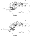
FIG. 3 shows a top plan view of a circuit board assembly and test strip ejector of the analysis device ofFIG. 1 , with the test strip ejector in the default/test position; -
FIG. 4 shows a top plan view of the circuit board assembly and test strip ejector similar toFIG. 3 , - after the test strip ejector is displaced to the ejection position;
-
FIG. 5 shows a top front left perspective view of a test strip sled of the present disclosure; -
FIG. 6 shows a bottom front right perspective view of the test strip sled ofFIG. 5 ; -
FIG. 7 shows a top plan view of the test strip sled ofFIG. 5 ; -
FIG. 8 shows an end elevation view of the test strip sled ofFIG. 5 ; -
FIG. 9 shows a side elevation view of the circuit board assembly ofFIG. 3 ; -
FIG. 10 shows a front end elevation view of the circuit board assembly ofFIG. 3 ; -
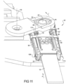
FIG. 11 shows a front left end perspective view of the test strip eject mechanism ofFIG. 3 ; -
FIG. 12 shows a front right end perspective view of the test strip eject mechanism ofFIG. 3 ; -
FIG. 13 shows a rear left end perspective view of the test strip eject mechanism ofFIG. 12 ; -
FIG. 14 shows a front right end perspective view of the test strip eject mechanism ofFIG. 4 ; -
FIG. 15 shows a bottom plan view of a circuit board assembly and test strip ejector modified from the analysis device ofFIG. 1 , with the test strip ejector in the default/test or neutral position; -
FIG. 16 shows a bottom plan view of the circuit board assembly and test strip ejector similar to -
FIG. 15 , after the test strip ejector is displaced to the ejection position; -
FIG. 17 shows a top plan view of another aspect for a slider test strip ejection mechanism; -
FIG. 18 shows a top plan view of another aspect for a fulcrum operated test strip ejection mechanism; -
FIG. 19 shows a top plan view of another aspect for a push-button actuated test strip ejection mechanism; -
FIG. 20 shows a top plan view of another aspect for a gear and arm test strip ejection mechanism; -
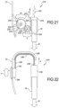
FIG. 21 shows a top plan view of another aspect for a multiple gear test strip ejection mechanism; -
FIG. 22 shows a top plan view of another aspect for a flexible track actuated test strip ejection mechanism; -
FIG. 23 shows a front perspective view of another aspect for a cable and piston actuated test strip ejection mechanism; -
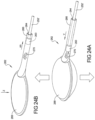
FIGS. 24A and 24B show front perspective views of another aspect for a fluid bladder actuated test strip ejection mechanism; -
FIGS. 25A, 25B, 25C, 25D show front elevational views of another aspect for a stored energy actuated test strip ejection mechanism; -
FIG. 26 shows a front right perspective view of another aspect for a roller displacement test strip ejection mechanism; -
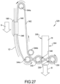
FIG. 27 shows a top plan view of another aspect for a combination racetrack/roller test strip ejection mechanism; -
FIGS. 28A and 28B show partial cross sectional front elevational views of another aspect for an electric motor actuated test strip ejection mechanism; -
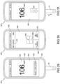
FIG. 29 shows a top plan view of an analysis device having a push button screen for automatic test strip ejection; -
FIG. 30 shows a top plan view of the analysis device ofFIG. 29 push button screen for selection of test strip ejection force; -
FIG. 31 shows a top plan view of the analysis device ofFIG. 29 push button screen for manual selection of test strip ejection velocity; and -
FIG. 32 shows a diagram of a motor operated medical analysis device test strip ejector system. - Corresponding reference numerals indicate corresponding parts throughout the several views of the drawings. The drawings described herein are for illustrative purposes only of selected embodiments and not all possible implementations, and are not intended to limit the scope of the present disclosure.
- Example embodiments will now be described more fully with reference to the accompanying drawings.
- Referring now to
FIG. 1 , ananalysis device 10 of a teststrip ejector system 11, which can be used for example for testing blood glucose levels, includes ahousing 12 upon which a digital readout is provided indicating the results of a body fluid test conducted by theanalysis device 10. Anejection button 16 is depressed following completion of the test to eject atest strip 18 which was previously received in a loading direction "A" inhousing 12. Upon depression of theejection button 16, thetest strip 18 is ejected in an ejection direction "B". The user of thetest strip 18 initially insertstest strip 18 intoanalysis device 10 so thetest strip 18 is recognized, and then removes and doses and then again manually inserts the dosedtest strip 18 in the loading direction "A". After analyses, subsequent operation ofejection button 16 ejects thetest strip 18. Alternately, the user can manually pull thetest strip 18 in the ejection direction "B" to manually remove the test strip. - Referring to
FIG. 2 ,test strip 18 is slidably received via a teststrip receiving port 20 created in a first end ofanalysis device 10. The teststrip receiving port 20 is sized to slidably receive thetest strip 18 while generally preventing twisting or rotation, such as a racking rotation, due to lateral or side-to-side displacement of the test strip. - Referring to
FIG. 3 and again toFIGS. 1 and 2 , with thehousing 12 removed for clarity, the components of acircuit board assembly 22 are visible.Circuit board assembly 22 includes a printedcircuit board 24 such as a printed circuit board having multiple components attached thereto.Housing 12 further includes amechanism assembly 26 which can be biased prior to or upon receipt of thetest strip 18 and can apply a displacement force or a biasing force to eject thetest strip 18.Mechanism assembly 26 includesejection button 16 and an axiallyrotatable mounting pin 28 which is rotatable with respect to a longitudinalpin center axis 30 which is affixed to a stationary component which would be on the PCB, housing, or some other nearby component. A member such as anactuator arm 32 is connected to mountingpin 28 and therefore co-rotates as mountingpin 28 axially rotates with respect to longitudinalpin center axis 30. Theejection button 16 is biased using an ejectionbutton biasing member 34 to return to the extended position shown following depression by the user. Manual depression ofejection button 16causes mounting pin 28 and thereforeactuator arm 32 to rotate, which directly contacts and slidably displaces asled 36 in the ejection direction "B". Thesled 36 is slidably and connectably engaged with respect to opposed and parallel oriented first andsecond guide rails second guide rails circuit board 24. Thesled 36 slides with respect to and is externally engaged to each of the first andsecond guide rails FIGS. 11 and12 . Asled post 42 which is generally cylindrical in shape is directly and fixedly connected tosled 36 and is slidably and rotatably received within anelongated slot 44 created inactuator arm 32. - Referring to
FIG. 4 and again toFIGS. 1-3 , after completion of the test by theanalysis device 10, thetest strip 18 is ejected fromhousing 12 by depression ofejection button 16.Actuator arm 32 rotates in a clockwise direction, as viewed inFIG. 4 , having sled post 42 engaged withsled 36 within elongatedslot 44, displacingsled 36 in the ejection direction "B" and thereby dischargingtest strip 18. The amount of force applied by the user toejection button 16 determines the force applied byactuator arm 32 and sled post 42 tosled 36 to ejecttest strip 18. The higher the applied force, the greater the velocity of ejection oftest strip 18. Therefore, the force received (Fr) to eject thetest strip 18 is a function of the force applied (Fa) toejection button 16 which is greater than the opposing biasing force (Fo) of ejection button biasing member 34 (Fr = Fa - Fo).Test strip 18 can therefore be ejected with enough force/velocity to directtest strip 18 into a trash or biohazard container (not shown) when not positioned directly over the container, or ifanalysis device 10 is held directly over the trash or biohazard container, a reduced force applied toejection button 16 will pushtest strip 18 out to subsequently fall by gravity. Whenejection button 16 is released, the biasing force of ejectionbutton biasing member 34returns ejection button 16 to its fully extended position. - With continuing reference to
FIG. 3 , theactuator arm 32 is shown in a test strip analysis position reached by a counterclockwise rotation with respect to longitudinalpin center axis 30. The test strip analysis position can be provided in each of two aspects. In a first aspect, in addition to biasingejection button 16,actuator arm 32 is also normally biased by ejectionbutton biasing member 34 to the counterclockwise rotated position shown inFIG. 3 , which prepositions theactuator arm 32 and thesled 36 in a neutral position (defined in this aspect as the position shown inFIG. 3 ) ready for receipt oftest strip 18. In this aspect,test strip 18 is freely manually loaded intohousing 12 until a strip end contacts or nearly contacts thesled 36. In the neutral position ofsled 36 defined in reference to the first aspect test position, it is desirable that a clearance be retained between thetest strip 18 andsled 36 during the analyses phase (which is shown and described in reference toFigure 13 ). After testing/analyses is complete,ejection button 16 is depressed against the biasing force of ejectionbutton biasing member 34, causing rotation ofactuator arm 32, and thesled 36 is displaced in the ejection direction "B", thereby dischargingtest strip 18. - With continuing reference to
FIGS. 3 and 4 , the test strip analysis position shown inFIG. 3 in a second aspect is reached by displacingsled 36 in the loading direction "A" from an initial position ofsled 36 as shown inFIG. 4 by manual insertion of thetest strip 18. The force of insertion oftest strip 18 slidably displacessled 36 in the loading direction "A" which directly rotates theactuator arm 32 in a counterclockwise direction. As thetest strip 18 is inserted in the loading direction "A", contact betweentest strip 18 andsled 36 occurs in arail cavity 41 which is created between the first andsecond guide rails elongated slot 44 permits actuatorarm 32 to rotate with respect to longitudinalpin center axis 30 in response to a load applied from a sliding motion in the loading direction "A" of both thetest strip 18 andsled 36. In this aspect, the sliding motion ofsled 36 is therefore translated into a rotational motion ofactuator arm 32 by contact betweensled post 42 and the wall ofelongated slot 44. - Displacement of
ejection button 16 causes rotation of the mountingpin 28 in a clockwise direction as viewed with respect toFIG. 4 . As theactuator arm 32 rotates in the clockwise direction, a force is applied via contact betweenactuator arm 32 and sled post 42 such that the rotational motion ofactuator arm 32 is translated into an axial sliding motion oftest strip 18 in the ejection direction "B". Thetest strip 18 which is in direct contact withsled 36 is ejected in the ejection direction "B" as thesled 36 is induced to slide in the ejection direction "B". Thetest strip 18, during test strip loading in the second aspect described above, and during the ejection step for both aspects, is in direct contact with each of opposed first andsecond contact legs sled 36, and positioned between deflectable legs which will be described in reference toFIG. 5 .Test strip 18 when positioned withinrail cavity 41 directly contacts first andsecond contact legs sled 36 intorail cavity 41. - Referring to
FIG. 5 , the first andsecond contact legs first contact leg 46 applies equally tosecond contact leg 48.First contact leg 46 is substantially rigid and includes aplanar leg portion 50 having acontact face 52 facing away fromsled post 42. The contact face 52 of each of the first andsecond contact legs test strip 18 for initially displacing thesled 36 in the loading direction "A" in the second aspect discussed herein, and for ejecting thetest strip 18 fromanalysis device 10 in both the first and second aspects. The provision of the two spaced apart contact faces 52, 52' of the first andsecond contact legs sled 36 that would occur using only a single contact point of a single pin or leg, therefore further reducing the chance of racking thesled 36 during ejection. - The
sled post 42 has acylindrical body 54 which is perpendicularly oriented with respect to aplanar body portion 56 ofsled 36. According to several embodiments,sled 36 is made of a metal such as stainless steel, to maximize a stiffness-to-weight ratio ofsled 36. Other materials forsled 36 can also be used, including plastics. According to severalaspects sled post 42 is created of a polymeric material having a low coefficient of friction such as polyoxymethylene (POM). A POM material or a similar material having a low coefficient of friction is selected forsled post 42 to maintain the shape ofsled post 42 and to minimize frictional resistance betweensled post 42 andactuator arm 32 as sled post 42 slides withinelongated slot 44 and asactuator arm 32 rotates with respect tosled post 42. According to other aspects, in lieu of a separate part,sled post 42 can be an integral extension of the material ofsled 36 and made such as by a staking, drawing or similar process during manufacture ofsled 36. In these aspects,sled post 42 can be cylindrical, dome shaped, or other shape as the manufacturing process allows. In these aspects, it is also desirable to provide a coating of a material such as polytetrafluoroethylene (PTFE) at least onsled post 42 to minimize frictional resistance betweensled post 42 andactuator arm 32. - With continuing reference to
FIG. 5 and again toFIGS. 3 and 4 ,sled 36 includes proximately positioned first andsecond legs fourth legs second legs sled post 42 according to several aspects is centrally located with respect to each of the first, second, third, andfourth legs fifth leg 66 can also be provided in a spaced apart relationship with respect to first andsecond legs first leg 58,second leg 60, andfifth leg 66 define a first side leg set 67. Similarly, asixth leg 68 can be provided in a spaced apart relationship with respect to third andfourth legs third leg 62,fourth leg 64, andsixth leg 68 together define a second side leg set 69. Second side leg set 69 is a mirror image of first side leg set 67. According to several aspects, third andfourth legs second legs sixth legs second guide rails - Each of the
individual legs sixth leg 68 applies also to each of the first throughfifth legs legs planar body portion 56 with respect tosled post 42 and is therefore oriented downwardly as viewed inFIG. 5 . Each of the legs includes an innerconcave leg portion 70 directly connected to anengagement portion 72 which is oppositely directed with respect to innerconcave leg portion 70. Directly connected toengagement portion 72 is anend portion 74 which is oppositely directed with respect toengagement portion 72 such that innerconcave leg portion 70,engagement portion 72, andend portion 74 together substantially define an S-shaped portion when viewed from an end ofsled 36 as will be evident inFIG. 8 . It is noted that first andsecond contact legs fifth legs sixth legs concave leg portion 70,engagement portion 72, orend portion 74. - Referring to
FIG. 6 and again toFIG. 5 ,sled post 42 includes a post connection end 76 which extends throughplanar body portion 56 such that post connection end 76 is positioned on alower body face 78 side ofplanar body portion 56. Post connection end 76 can be mechanically connected toplanar body portion 56 using a plurality of connection methods, including staking, forming or adhesively boding, to fix post connection end 76 with respect toplanar body portion 56. In addition, apost retainer 80 can also be included with post connection end 76, which can be biased into contact withplanar body portion 56 or displaced, such as by a staking operation, such thatpost retainer 80 acts as a retention member to further retain the fixed position ofpost connection end 76. According to additional embodiments, afriction reduction coating 81 made from a material having a low coefficient of friction, such as polytetrafluoroethylene (PTFE), can be provided as a coating on at least thelower body face 78 ofplanar body portion 56.Friction reduction coating 81 can also be provided on both sides or faces ofsled 36 prior to or following formation of any of the legs. - Referring to
FIG. 7 and again toFIGS. 5-6 , as previously notedsled post 42 is centrally positioned with respect to each of the first andsecond legs fourth legs central axis 82 ofsled post 42 is aligned with a sledlongitudinal axis 84. According to additional aspects, features such as first andsecond body notches first end 90 ofplanar body portion 56. First andsecond body notches individual sleds 36 can be perforated from a strip of material (not shown) defining multiple ones ofsleds 36. In addition, athird body notch 92 can be created at a bodysecond end 94 ofplanar body portion 56. The purpose forthird body notch 92 will be better described in reference toFIG. 14 . According to several embodiments, a first leg-to-leg spacing "C" is provided between first andsecond legs fourth legs first leg 58 andthird leg 62 and bothfifth leg 66 andsixth leg 68, respectively. Second leg-to-leg spacing "D" is selected such that a third leg-to-leg spacing "E" between, for example,second leg 60 andfifth leg 66 is greater than first leg-to-leg spacing "C". The purpose for this increased spacing used for second leg-to-leg spacing "D" will be described in better detail in reference toFIGS. 12 and14 . - It is noted that the location of first and
second contact legs fourth legs sixth legs central axis 82, however, to help mitigate against a racking or rotation motion ofsled 36 during operation, the first andsecond contact legs central axis 82, while providing clearance for die or stamp tooling during creation of these legs. Racking is defined herein as axial rotation ofsled 36 with respect to longitudinal postcentral axis 82, which if occurring could cause thesled 36 to bind during sliding travel on the first andsecond guide rails sled 36 such aslegs - Referring to
FIG. 8 and again toFIGS. 3 and5-7 ,sled post 42 and its longitudinal postcentral axis 82 are oriented substantially perpendicular with respect to a bodyupper surface 96 ofplanar body portion 56. Each of the first andsecond contact legs central axis 82 and therefore are oriented substantially perpendicular with respect to bodyupper surface 96 andlower body face 78. Each of the first throughsixth legs third legs upper contact surface 98 is defined in inner concave leg portion 70', and an oppositely located secondupper contact surface 100 is provided with innerconcave leg portion 70" such that an upper contact surface spacing dimension "G" is defined between first and second upper contact surfaces 98, 100. A firstlower contact surface 102 is provided with inner concave leg portion 70', and an oppositely positioned secondlower contact surface 104 is provided with innerconcave leg portion 70". A lower contact surface spacing dimension "H" is greater than the upper contact surface spacing dimension "G", thereby defining an outwardly canted angle α for innerconcave leg portion 70" which is duplicated but oppositely directed with respect to innerconcave leg portion 70". The difference between upper and lower contact surface spacing dimensions "G", "H" helps prevent binding of the individual legs during sliding motion ofsled 36. A spacing or distance dimension betweenengagement portions 72', 72" is less than each of the upper or lower contact surface spacing dimensions "G", "H". The S-shape of each of thelegs engagement portion 72 externally contacts and captures one of the guide rails 38, 40, which together with the deflectable design of the legs thereby provides continuous, positive contact between the legs with the guide rails 38, 40 throughout the travel path ofsled 36, and limiting displacement of thesled 36 to only sliding motion in either the loading direction "A" or the opposite ejection direction "B", and further preventing thesled 36 from moving away from the guide rails 38, 40 during sliding motion. - Referring to
FIG. 9 and again toFIG. 3 ,sled 36 is shown in thetest strip 18 loaded or test/analysis position such that aplane 106 extending throughplanar body portion 56 ofsled 36 is oriented parallel to each oftest strip 18 and printedcircuit board 24.Actuator arm 32 rotates parallel with respect toplane 106, which therefore minimizes the potential for binding or racking ofsled 36 as it receives or ejectstest strip 18. - Referring to
FIG. 10 and again toFIGS. 3 and9 , astest strip 18 is slidably moved withinrail cavity 41,sled 36 is free to slidably displace either toward or away from the viewer, as shown in reference toFIG. 10 .Sled 36 is slidable but is contained with respect to a "Z" axis by sliding engagement of inner concave leg portion 70' with respect to a first guide railbulbous face 108 offirst guide rail 38, and with respect to innerconcave leg portion 70" by sliding engagement with respect to a second guide railbulbous face 110 ofsecond guide rail 40. Each of the first andsecond guide rails planar surface 112 of printedcircuit board 24. - Referring to
FIG. 11 and again toFIGS. 3 and10 , according to the second aspect described herein, astest strip 18 is slidably disposed into the teststrip receiving port 20 in the loading direction "A", a teststrip end wall 113 oftest strip 18 directly contacts each of the contact faces 52, 52' of first andsecond contact legs sled 36 also in the loading direction "A". As sled post 42 ofsled 36 is displaced in the loading direction "A", sled post 42 contacts actuatorarm 32 inelongated slot 44 and thereby rotatesactuator arm 32 in a loading rotational direction "J" with respect to the longitudinalpin center axis 30. For both the first and second aspects, astest strip 18 is received at the test position shown, multiple contact points of thetest strip 18 contact aconnector 111 positioned in the device, thereby making electrical contact with theconnector 111 to permit analyses of the fluid provided withtest strip 18.Connector 111 can include multiple, individual contact points that each align with one of the contact points of thetest strip 18. - Referring to
FIG. 12 , aclosure member 114 is provided between first andsecond guide rails strip receiving port 20, and further maintains parallel alignment betweentest strip 18 and boardplanar surface 112. Each of the first throughsixth legs sled 36 is positioned having the planar leg faces 105, 105' in sliding contact withupper surfaces 117, 117' of the first andsecond guide rails convex leg portion 115 wrapping partially about the first and second guide rail bulbous faces 108, 110, thereby individually externally connecting each of the first throughsixth legs second guide rails concave leg portion 70 of each of the first through sixth legs is in sliding contact with an oppositely facinglower surface 121, 121' of either the first or second guide railbulbous face sixth legs second guide rails sled 36 from lifting off in a direction perpendicular to the first andsecond guide rails upper surfaces 117, 117' of the first orsecond guide rails sled 36. Theengagement portions 72 of each of the first throughsixth legs lower surfaces 121, 121' of the first or second guide rail bulbous faces 108, 110 to further mitigate lifting of thesled 36 at any of its sliding positions. - It is noted that the multiple independent legs herein described as first through
sixth legs sled 36 however, according to further embodiments, any or all of the individual legs of either first or second side leg sets 67, 69 can be combined together and still include the features of innerconcave leg portion 70 andengagement portion 72. Therefore, a single leg, two legs, three legs or more than three deflectable legs can be provided on each side ofsled 36. The width and/or dimensions of the single leg or multiple legs on each side can also be varied. For example only, a single leg having a width corresponding to the outside end to outside end spacing of first andfifth legs first leg 58,second leg 60 andfifth leg 66. The use of multiple individual legs in place of single wide legs reduces surface leg area sliding friction ofsled 36 while providing maximum spacing between the end legs, such asfirst leg 58 andfifth leg 66, which maximizes a moment arm ofsled 36, thereby minimizing a racking or rotation ofsled 36 as it slides with respect to the first orsecond guide rails sled 36 to be mounted during an installation stage in a sled installation direction "K" oriented perpendicular to the first andsecond guide rails legs second guide rails sled 36 in sled installation direction "K" transverse to the loading direction "A" and the ejection direction "B". - Installation via sled installation direction "K" allows
sled 36 to be positioned directly over first andsecond guide rails actuator arm 32 without interfering with any other component mounted on printedcircuit board 24, or requiring the other component or components to be temporarily removed and/or installed at a later time than the installation ofsled 36. This allows for automated machine installation ofsled 36. During installation ofsled 36 in the sled installation direction "K", theend portion 74 of each of the individual legs deflects elastically outward with respect to the first or second guide railbulbous face engagement portion 72, 72' moves past the first or second guide railbulbous face engagement portion 72, 72' oppositely positioned about the first or second guide railbulbous face sled 36 is thereby slidably coupled to the first andsecond guide rails sled 36 to sliding motion in either of the loading or ejection directions "A", "B". - Referring to
FIG. 13 and again toFIG. 12 , in the neutral position ofsled 36 defined in reference to both the first and second aspects discussed above,test strip 18 is positioned in the fully inserted or test position. A clearance "M" can be provided between the teststrip end wall 113 oftest strip 18 and the contact faces 52, 52' of first andsecond contact legs sled 36 during the test/analyses phase. Provision of clearance "M" prevents any force being applied totest strip 18 in the ejection direction "B" during the test/analysis phase. - Referring to
FIG. 14 and again toFIGS. 3-12 ,third body notch 92 provides clearance forangled entrance lip 116 whensled 36 reaches its furthest displaced ejection position. Although contact betweenthird body notch 92 andangled entrance lip 116 can provide a positive stop forsled 36, according to several aspects, a preferred positive stop forsled 36 is provided by direct contact between first andsecond contact legs second stop face closure member 114. Following depression ofejection button 16,actuator arm 32 rotates in an ejection rotational direction "N", thereby creating direct contact between aslot wall 120 ofelongated slot 44 and an outer or perimeter surface ofsled post 42. This contact and counterclockwise rotation ofactuator arm 32 displacessled 36 in the ejection direction "B", allowing ejection or removal oftest strip 18. It is noted thatsled 36 is prevented from extending past either end of the first orsecond guide rails second contact legs second abutment face cover plate 128 seated between first andsecond guide rails Sled 36 therefore cannot extend past rail assembly first end 122 or an opposite rail assemblysecond end 124 due to the positive stop features. According to other aspects, it is possible to eliminate the positive stop features and prevent displacement ofsled 36 past either rail assembly first or second ends 122, 124 by limiting a rotation of mountingpin 28, and thereby limiting rotation ofactuator arm 32 between the fully ejected position and the fully loaded position ofsled 36. - With continuing reference to
FIGS. 8 and14 , the contact leg spacing dimension "F" of first andsecond contact legs second contact legs rail cavity 41 while providing as wide as possible contact leg spacing dimension "F" at the maximum width oftest strip 18. This also helps mitigate rotation or racking ofsled 36 and/ortest strip 18. - For operation, the test
strip ejector system 11 for receiving and ejectingtest strip 18 fromfluid analysis device 10 includes first andsecond guide rails rail cavity 41 between the guide rails 38, 40.Sled 36 includes first and second spatially separated contact faces 52, 52' positioned in therail cavity 41 and opposed first andsecond legs legs second guide rails Actuator arm 32 is rotatably connected to thefluid analysis device 10. Thesled 36 is coupled to theactuator arm 32 such that rotation of theactuator arm 32 in the loading rotational direction "J" moves the sled in the loading direction "A" to position thesled 36 in the test strip test position (shown inFIG. 3 ). Opposite rotation of theactuator arm 32 in the ejection rotational direction "P" operates to displace thesled 36 in the ejection direction "B" away from the test strip test position and to position the first and second contact faces 52, 52' in direct contact with thetest strip 18 to eject thetest strip 18 from thefluid analysis device 10. - Referring to
FIG. 15 and again toFIGS. 1-14 , ananalysis device 130 is modified fromanalysis device 10 to include asled 132 having four legs in lieu of six legs, including first, second, third andfourth legs sixth legs sled 36. The first andsecond guide rails sled post 42 ofsled 132 is rotatably connected toactuator arm 32. First andsecond contact legs sled 132 and therefore perform the same functions as first andsecond contact legs member 146 extending fromhousing 12 includes an arc-shapedsurface 148 which is directly contacted bysled post 42 and acts as a guide forsled post 42 during displacement ofsled 132. The mountingpin 28 is slidably received in a firstelongated slot 150 created in an ejectionbutton body extension 152 which is connected toejection button 16. In the sled neutral position shown,ejection button 16 and ejectionbutton biasing member 34 are fully extended, mountingpin 28 is positioned proximate to a first end of firstelongated slot 150, andsled 132 is positioned to receive atest strip 18. Adriver pivot pin 154 extends fromactuator arm 32, and according to several embodiments is integrally connected toactuator arm 32.Driver pin 154 is received in a secondelongated slot 156 created inbody extension 152, having a shorter length than firstelongated slot 150 to allow limited displacement ofdriver pin 154 during rotation ofactuator arm 32. Astop member 158 connected to structure ofhousing 12 provides a non-displaceable receiving point for ejectionbutton biasing member 34. - Referring to
FIG. 16 and again toFIG. 15 ,ejection button 16 is shown after depression which compresses ejectionbutton biasing member 34 againststop member 158 and slidably displacesejection button 16 andbody extension 152 in a release direction "Q". This motion ofbody extension 152 also displacesdriver pin 154 in the release direction "Q". Because mountingpin 28 is substantially fixed with respect tohousing 12, displacement ofdriver pin 154 in the release direction "Q" rotatesactuator arm 32 in the ejection rotational direction "N". Displacement in the release direction "Q" continues until, by the displacement ofbody extension 152, a second end of firstelongated slot 150 is positioned proximate to mountingpin 28 and the positions of mountingpin 28 anddriver pin 154 are reversed with respect to their positions in the neutral position shown inFIG. 15 . Rotation ofactuator arm 32 in the ejection rotational direction "N" displacessled 132 in the ejection direction "B". Subsequent release ofejection button 16 by the user allows the biasing force of ejectionbutton biasing member 34 to displacebody extension 152 andejection button 16 in a return direction "R", opposite to release direction "Q", thereby returningsled 132 in the loading direction "A" to the neutral position shown inFIG. 15 . - As noted herein, test strip ejectors and systems of the present disclosure can be used in meters by individual users having personal test meters. Test strip ejector systems of the present disclosure can also be incorporated in commercial devices such as hospital meters, for example rechargeable test meters recharged by installation in a base unit, and/or blood glucose meters such as ACCU-CHEK® Inform System glucose meters manufactured by Roche Diagnostics. The test strips used by such hospital and glucose test meters can be configured differently from the test strips identified herein to conform to the requirements of the test and/or test meter, however the test strip ejector systems of the present disclosure will be similarly configured and function in a similar manner.
- In addition, test strip ejectors and systems of the present disclosure can also be incorporated in individual or commercial devices such as blood coagulant test meters, for example blood clotting time test meters such as the CoaguChek® XS System coagulant test meters manufactured by Roche Diagnostics. The test strips used by such blood coagulant test meters can be configured differently from the test strips identified herein to conform to the requirements of the test and/or test meter, however the test strip ejector systems of the present disclosure will be similarly configured and function in a similar manner.
- Test strip ejectors of the present disclosure offer several advantages. The following discussion of
analysis device 10 applies equally toanalysis device 130.Sled 36 of the present disclosure provides a sliding motion member that is retained by its deflectable legs externally to a parallel set ofguide rails rail cavity 41 between the guide rails for sliding motion of thetest strip 18 in direct contact withsled 36. The first andsecond contact legs sled 36 extend intorail cavity 41 so continuous contact withtest strip 18 is maintained whentest strip 18 is positioned inrail cavity 41 during sliding motion, at least in the ejection direction "B". In the neutral position ofsled 36 defined in reference to the first aspect test position, a clearance "M" can be maintained between thetest strip 18 andsled 36 during the analyses phase to prevent any force being applied totest strip 18 in the ejection direction "B" during the test/analysis phase. According to other aspects, continuous contact between first andsecond contact legs sled 36 withtest strip 18 can be maintained during all times whentest strip 18 is positioned inrail cavity 41. The use of multiple elasticallyflexible legs sled 36 to minimize racking motion while also allowing for installation ofsled 36 in a "Z" axis, perpendicular to the orientation of the guide rails. Thesled post 42 being received in an elongated slot ofactuator arm 32 converts a rotational motion ofactuator arm 32 into the sliding motion ofsled 36, minimizing the space required for theejection mechanism assembly 26 on printedcircuit board 24, while allowing theejection mechanism assembly 26 to be mounted to a side of the guide rails in lieu of in axial relationship with the guide rails. - Referring to
FIG. 17 and again toFIGS. 1-5 , with thehousing 12' substantially removed for clarity, amechanism assembly 160 is modified frommechanism assembly 26 and can be biased prior to or upon receipt of thetest strip 18, and can apply a displacement force or a biasing force to either eject thetest strip 18, or to retract sled 36' after an ejection operation. The sled 36' is slidably and connectably engaged with respect to opposed and parallel oriented first andsecond guide rails FIG. 17 for clarity. In the aspect shown inFIG. 17 ,mechanism assembly 160 includes a biasingmember 162 such as a tension spring that is biased/extended during ejection of thetest strip 18, thereby creating a biasing force acting in the loading direction "A". The biasingmember 162 can be directly connected to sled 36'. Sled 36' in turn is directly and non-rotatably connected to a first end of a member such as anactuator arm 164 which is a beam structure having longitudinal rigidity to retain a longitudinal shape during operation under both the biasing load of biasingmember 162 and a load manually applied by a user.Actuator arm 164 is directly connected at an opposite second end to anejection button 166 which is slidably connected tohousing 12' using an outwardly extendingbutton portion 168.Mechanism assembly 26 is shown in the test strip loaded/test position having the biasing force of biasingmember 162 acting in the loading direction "A" to retain sled 36' andactuator arm 164 in the test position. Atest strip 18 is manually loaded in the loading direction "A" when desired and the loading operation does not displace members ofmechanism assembly 160. - When ejection of
test strip 18 is desired, the user manually displacesejection button 166 in a sliding direction "S" which is parallel with the ejection direction "B". The velocity imparted toejection button 166 by the user determines the velocity of discharge oftest strip 18. Asejection button 166 is displaced in the sliding direction "S",actuator arm 164 is directly displaced, together with sled 36' in the ejection direction "B", thereby displacingtest strip 18 and simultaneously extending biasingmember 162, creating a return biasing force in biasingmember 162. When the user releasesejection button 166, the biasing force ofextended biasing member 162 retracts sled 36',actuator arm 164, andejection button 166 in the loading direction "A" to the initial or test position shown, awaiting manual insertion of a next test strip. - Referring to
FIG. 18 and again toFIGS. 1-5 and17 , with thehousing 12' again substantially removed for clarity, amechanism assembly 170 is modified frommechanism assembly 160 and can be biased prior to or upon receipt of thetest strip 18, and can apply a displacement force or a biasing force to either eject thetest strip 18, or to retract sled 36' after an ejection operation. The sled 36' is slidably and connectably engaged with respect to opposed and parallel oriented first andsecond guide rails FIG. 18 for clarity. In the aspect shown inFIG. 18 ,mechanism assembly 170 includes biasingmember 162 acting as a tension spring that is biased/extended during ejection of thetest strip 18, thereby creating a biasing force acting in the loading direction "A". The biasingmember 162 can be directly connected to sled 36'. Sled 36' in turn is rotatably connected to afirst end 171 of a fulcrum member such as anactuator arm 172 which is a beam structure having longitudinal rigidity to retain a longitudinal shape during operation under both the biasing load of biasingmember 162 and a load manually applied by a user.Actuator arm 172 is rotatably mounted to structure ofhousing 12' or to printedcircuit board 24 using a mountingpin 174. Thefirst end 171 ofactuator arm 172 slidably receives afirst pin 176 connected to sled 36' in anelongated slot 178 ofactuator arm 172. The elongated slot allows sliding motion of sled 36' asactuator arm 172 rotates about mountingpin 174. Asecond end 179 ofactuator arm 172 oppositely positioned with respect to thefirst end 171 is rotatably connected toejection button 166 using asecond pin 180 extending fromejection button 166 that is received in anaperture 181 created in thesecond end 179 ofactuator 172 sized to only rotatably receivesecond pin 180. - The use of mounting
pin 174 provides for an opposite direction of displacement ofejection button 166 to ejecttest strip 18 compared tomechanism assembly 160. When ejection oftest strip 18 is desired, the user manually displacesejection button 166 in a sliding direction "T" which is opposite to sliding direction "S", and parallel with the ejection direction "B". Similar tomechanism assembly 160, the velocity imparted toejection button 166 by the user determines the velocity of discharge oftest strip 18. Asejection button 166 is displaced in the sliding direction "T",actuator arm 172 is directly rotated about mounting pin 174 (in a clockwise direction as viewed inFIG. 18 ), transferring a force applied throughsecond pin 180 tofirst pin 176 to displace sled 36' in the ejection direction "B". This rotation ofactuator arm 172 displacestest strip 18 and simultaneously extends biasingmember 162, creating a return biasing force in biasingmember 162. When the user releasesejection button 166, the biasing force ofextended biasing member 162 retracts sled 36', oppositely rotates actuator arm 172 (in a counter-clockwise direction as viewed inFIG. 18 ), and returnsejection button 166 parallel to the ejection direction "B" to the initial or test position shown, awaiting manual insertion of a next test strip. It is noted that the location or position of mountingpin 174 along the length ofactuator arm 172 can increase or decrease the force applied to sled 36'. For example, with mountingpin 174 substantially centrally positioned inactuator arm 172 as shown, the amount of displacement ofejection button 166 substantially equals the amount of displacement of sled 36'. If mountingpin 174 is moved closer tofirst pin 176, a greater longitudinal displacement ofejection button 166 would be required to achieve the same displacement of sled 36'. This also results in a lower force requirement by the user to displace sled 36' due to the mechanical advantage gained. Conversely, if mountingpin 174 is moved closer tosecond pin 180, a lesser longitudinal displacement ofejection button 166 would be required to achieve the same displacement of sled 36'. This also necessitates a greater force requirement by the user to displace sled 36' due to the mechanical advantage lost, but can increase a velocity of displacement oftest strip 18. - Referring to
FIG. 19 and again toFIGS. 1-5 and17-18 , with thehousing 12' again substantially removed for clarity, amechanism assembly 182 is modified frommechanism assembly 160 to include apush rod 184 and a modifiedsled 185, and can be biased prior to or upon receipt of thetest strip 18, and can apply a displacement force or a biasing force to either eject thetest strip 18, or to retractsled 185 after an ejection operation. Thesled 185, similar tosled 36, can be slidably and connectably engaged with respect to opposed and parallel oriented first andsecond guide rails FIG. 19 for clarity. In the aspect shown inFIG. 19 ,mechanism assembly 182 includes biasingmember 162 such as a tension spring that is biased/extended during ejection of thetest strip 18, thereby creating a biasing force acting in the loading direction "A" to retainsled 185 in the test strip test position shown. The biasingmember 162 can be directly connected tosled 185.Sled 185 in turn is connected to a first end 186 of the member oractuator arm 184 using adrive pin 187.Actuator arm 184 is a beam structure having longitudinal rigidity to retain a longitudinal and axial shape during operation under both the biasing load of biasingmember 162 and a load manually applied by a user.Actuator arm 184 is directly connected at an oppositesecond end 188 to anejection button 190 which is displaceable from the normal or test position shown by manual displacement in an inward direction "U".Mechanism assembly 182 is shown in the test strip loaded/test position having the biasing force of biasingmember 162 acting in the loading direction "A" to retainsled 185 andactuator arm 184 in the test position. Atest strip 18 is manually loaded in the loading direction "A" when desired and the loading operation does not displace members ofmechanism assembly 182. - When ejection of
test strip 18 is desired, the user manually displacesejection button 190 in the inward direction "U" which is oriented perpendicular to the ejection direction "B". The velocity/force imparted toejection button 190 by the user determines the velocity of discharge oftest strip 18. Asejection button 190 is displaced in the inward direction "U",actuator arm 184 is directly inwardly displaced further intohousing 12'. Thedrive pin 187 which is directly and fixedly connected to first end 186 ofactuator arm 184 is slidably received in anelongated slot 192 created insled 185.Elongated slot 192 is oriented at an angle β with respect to a longitudinalcentral axis 194 ofsled 185. Asejection button 190 is displaced in the inward direction "U",drive pin 187 displaces from a first end ofelongated slot 192 toward an opposite end ofelongated slot 192. The force imparted bydrive pin 187 to the wall ofelongated slot 192 causes axial displacement ofsled 185 in the ejection direction "B", thereby displacingtest strip 18 and simultaneously extending biasingmember 162, creating a return biasing force in biasingmember 162. When the user releasesejection button 190, the biasing force ofextended biasing member 162 retractssled 185 in the loading direction "A" to the initial or test position shown, awaiting manual insertion of a next test strip. This motion ofsled 185 acts ondrive pin 187 which slides from the second to the first end ofelongated slot 192 to outwardly displace bothactuator arm 184 andejection button 190. It is noted that angle β can range between approximately 20 to 60 degrees, and the angle selected can change the amount of displacement ofsled 185. For example, a lower angle of approximately 20 degrees forelongated slot 192 produces a minimum displacement ofsled 185, and conversely, a greater angle of approximately 60 degrees produces a maximum displacement ofsled 185. According to other aspects,elongated slot 192 can be replaced by acurved slot 196, which can further increase or decrease the amount of displacement ofsled 185 depending on the direction of curvature ofcurved slot 196. - Referring to
FIG. 20 and again toFIGS. 1-5 and17-18 , with thehousing 12' again substantially removed for clarity, amechanism assembly 198 is modified frommechanism assembly 170 and can be biased prior to or upon receipt of thetest strip 18, and can apply a displacement force or a biasing force to either eject thetest strip 18, or to retract asled 200 after an ejection operation. Thesled 200 is slidably and connectably engaged with respect to opposed and parallel oriented first andsecond guide rails FIG. 20 for clarity. In the aspect shown inFIG. 20 ,mechanism assembly 198 includes biasingmember 162 acting as a tension spring that is biased/extended during ejection of thetest strip 18, thereby creating a biasing force acting in the loading direction "A". The biasingmember 162 can be directly or indirectly connected tosled 200.Sled 200 in turn is rotatably connected to afirst end 201 of a member such as anactuator arm 202 which is a beam structure having longitudinal rigidity to retain a longitudinal shape during operation under both the biasing load of biasingmember 162 and a load manually applied by a user. Afirst pin 203 fixedly connected tofirst end 201 ofactuator arm 202 is rotatably connected, either directly tosled 200, or to astructure 204 extending fromsled 200. Asecond end 205 ofactuator arm 202 is rotatably mounted to structure ofhousing 12' or to printedcircuit board 24 using a mountingpin 206 which is fixed in position. Agear 208 is fixed toactuator arm 202 and also rotatably mounted to mountingpin 206 and includesmultiple gear teeth 210. Thegear teeth 210 are meshed with teeth of a rack gear set 212 extending intohousing 12' from anejection button 214.Ejection button 214 is slidably displaceable from the normal or test position shown in the sliding direction "T" by manual displacement by a user. - The use of mounting
pin 206 andgear 208 provides for an opposite direction of displacement ofejection button 214 to ejecttest strip 18 compared tomechanism assembly 160, and similar tomechanism assembly 170. When ejection oftest strip 18 is desired, the user manually displacesejection button 214 in the sliding direction "T" which is parallel to but oppositely directed with respect to ejection direction "B". Similar tomechanism assemblies ejection button 214 by the user determines the velocity of discharge oftest strip 18. Asejection button 214 is displaced in the sliding direction "T", the teeth of rack gear set 212 meshing withgear teeth 210 rotate actuator arm 202 (in a clockwise direction as viewed inFIG. 20 ), transferring a force applied throughfirst pin 203 to displacesled 200 in the ejection direction "B". This rotation ofactuator arm 202 displacestest strip 18 and simultaneously extends biasingmember 162, creating a return biasing force in biasingmember 162. When the user releasesejection button 214, the biasing force ofextended biasing member 162 retractssled 200, oppositely rotates actuator arm 202 (in a counter-clockwise direction as viewed inFIG. 20 ), and returnsejection button 214 parallel to the ejection direction "B" to the initial or test position shown, awaiting manual insertion of a next test strip. It is noted that the diameter ofgear 208 and number ofteeth 210, as well as the length ofactuator arm 202 can increase or decrease the amount of displacement ofsled 200. - Referring to
FIG. 21 and again toFIGS. 1-5 and20 , with thehousing 12' again substantially removed for clarity, amechanism assembly 216 is modified frommechanism assembly 198 and can be biased prior to or upon receipt of thetest strip 18, and can apply a displacement force or a biasing force to either eject thetest strip 18, or to retract asled 218 after an ejection operation. Thesled 218 is slidably and connectably engaged with respect to opposed and parallel oriented first andsecond guide rails FIG. 21 for clarity. In the aspect shown inFIG. 21 ,mechanism assembly 216 includes biasingmember 162 acting as a tension spring that is biased/extended during ejection of thetest strip 18, thereby creating a biasing force acting in the loading direction "A". The biasingmember 162 can be directly or indirectly connected tosled 218.Sled 218 includes a plurality ofteeth 220 of a rack gear set 222 that mesh withteeth 224 of afirst gear 226.First gear 226 is rotatably connected tohousing 12' or to printedcircuit board 24 using afirst mounting pin 228.Teeth 224 mesh withteeth 230 of asecond gear 232, which is rotatably connected tohousing 12' or to printedcircuit board 24 using asecond mounting pin 234. According to several aspects, a portion ofteeth 230 extend outwardly ofhousing 12' to be manually rotated by a user. According to other aspects, a portion ofteeth 230 are accessible by a user via acavity 235 created inhousing 12' to provide access toteeth 230.First gear 226 rotates in a first direction "V" (counterclockwise as viewed inFIG. 21 ) by manual rotation ofsecond gear 232 in a second direction "W" (clockwise as viewed inFIG. 21 ) opposite to first direction "V". Rotation offirst gear 226 meshes theteeth 220 of rack gear set 222, thereby displacingsled 218 andtest strip 18 in the ejection direction "B". Release ofsecond gear 232 by the user permits the biasing force of biasingmember 162 to returnmechanism assembly 216 to its normal, test position to manually receive anext test strip 18. - Referring to
FIG. 22 and again toFIGS. 1-5 and20 , with thehousing 12' again substantially removed for clarity, amechanism assembly 234 includes asled 236 operable to receive and/or eject atest strip 18.Sled 236 is connected to a first connectingend 238 of aflexible rail member 240. A second connectingend 242 offlexible rail member 240 is connected to anejection button 244 which slidably operates similar toejection button 166.Sled 236 is shown in the normal or test position having thetest strip 18 manually loaded in the loading direction "A". To ejecttest strip 18,ejection button 244 is displaced in the sliding direction "T" which is opposite to ejection direction "B". Theflexible rail member 240 is slidably retained by the contour of aguide member 246 fixed inhousing 12'. The displacement ofejection button 244 displaces the entire length offlexible rail member 240 such thatsled 236 is displaced by the same distance asejection button 244 is displaced. A velocity or force applied toflexible rail member 240 directly affects the velocity of displacement oftest strip 18. - Referring to
FIG. 23 and again toFIGS. 1-5 and22 , with thehousing 12' again substantially removed for clarity, amechanism assembly 250 is modified frommechanism assembly 234 to omitsled 236.Mechanism assembly 250 includes aflexible rail member 252 similar toflexible rail member 240, but having apiston 254 defining a free end thereof.Flexible rail member 252 is slidably received in arail housing 256 withpiston 254 positioned to be able to directly contacttest strip 18. An operatingend 258 offlexible rail member 252 is acted on by a manual operator such asejection button 166 previously described herein (not shown in this view for clarity) operable to displaceflexible rail member 252 in a displacement direction "X". One ormore clamps 260 can be used to orientrail housing 256 to alignpiston 254 withtest strip 18 such that displacement offlexible rail member 252 causes ejection oftest strip 18 in the ejection direction "B". Similar to previously described mechanism assemblies of the present disclosure, a velocity or force applied toflexible rail member 252 directly affects the velocity of displacement oftest strip 18. - Referring to
FIGS. 24A and 24B and again toFIGS. 1-5 and23 , with thehousing 12' again substantially removed for clarity, amechanism assembly 262 is modified frommechanism assembly 250 to add asecond piston 263 at an opposite end of flexible rail member 252' with respect to piston 254 (not shown for clarity).Mechanism assembly 262 includes flexible rail member 252' havingsecond piston 263 slidably disposed in ahollow bore 264 of arail housing 266.Rail housing 256 is integrally connected to abladder assembly 268 which when expanded draws a fluid 270 such as air into a chamber ofbladder assembly 268. When compressed for example in a compression direction "Z"bladder assembly 268 displaces fluid 270 from within the chamber ofbladder assembly 268 intohollow bore 264. Withsecond piston 263 forming a sliding seal withinhollow bore 264,fluid 270 displacessecond piston 263 and therefore flexible rail member 252' in a displacement direction "AA" which acts to displacetest strip 18 as described in reference toFIG. 23 . Similar to previously described mechanism assemblies of the present disclosure, a velocity or force applied byfluid 270 onsecond piston 263 of flexible rail member 252' directly affects the velocity of displacement oftest strip 18. According to other aspects, fluid 270 can be a hydraulic fluid, or substantially any fluid able to displacesecond piston 263 by compressingbladder assembly 268. - Referring to
FIGS. 25A-25D and again toFIGS. 1-5 andFIG. 23 , with thehousing 12' again substantially removed for clarity, amechanism assembly 272 operates using the stored energy of multiple biasing members to eject atest strip 18.Mechanism assembly 272 receivestest strip 18 in the loading direction "A" into a first opening orcavity 274 that communicates with ahousing 276. Afirst biasing member 278 such as a compression spring is positioned in contact with anend wall 280 ofhousing 276 in a second opening orcavity 282, which is larger thanfirst cavity 274. As shown inFIGS. 25A and 25B , thetest strip 18 when inserted contacts asled 284 slidably disposed insecond cavity 282, which contacts an end of first biasingmember 278 facing away fromend wall 280 and compresses first biasingmember 278. As shown inFIG. 25A , asecond biasing member 286 such as a leaf or plate spring may be connected tosled 284 and initially extends freely into thefirst cavity 274 and is in sliding contact with anupper wall 288 offirst cavity 274. As thesled 284 is displaced in the loading direction "A" bytest strip 18, afree end 290 ofsecond biasing member 286 is displaced intosecond cavity 282 where the biasing force ofsecond biasing member 286 displacesfree end 290 in a direction "BB" away fromsled 284 and into contact with asecond end wall 292 ofsecond cavity 282, where a stiffness ofsecond biasing member 286 restrained againstsecond end wall 292 prevents first biasingmember 278 from acting to ejecttest strip 18. - As shown in
FIGS. 25B-25D , the piston 254' of flexible rail member 252' is slidably received in an aperture ofhousing 276 directly in alignment with second biasingmember 286. To ejecttest strip 18, a force acting on flexible rail member 252' displaces piston 254' in a displacement direction "CC" intosecond cavity 282 and into direct contact with second biasingmember 286, thereby forcingfree end 290 away from contact withsecond end wall 292. This permits the biasing force of compressed first biasingmember 278 to displacesled 284 andfree end 290 into thefirst cavity 274. The biasing force of first biasingmember 278 overcomes the frictional contact between piston 254' and second biasingmember 286 such thatsled 284 is displaced in the ejection direction "B" to ejecttest strip 18. Release of the force acting on flexible rail member 252' and piston 254' permits biased retraction of piston 254' back to the original position shown inFIG. 25A . Only a single ejection speed oftest strip 18 is provided bymechanism assembly 272, which is predetermined by the biasing force, length, spring constant, and the like of the first andsecond biasing members - Referring to
FIG. 26 and again toFIGS. 1-5 , with thehousing 12' again substantially removed for clarity, amechanism assembly 294 operates using a frictional contact ejection roller to eject atest strip 18.Mechanism assembly 294 receivestest strip 18 in the loading direction "A" into aU-shaped trough 296 having opposed first andsecond side walls wall 302 oriented substantially perpendicular to first andsecond side walls frictional roller 304 is rotatably supported by first andsecond side walls pin 306 extending through both first andsecond side walls frictional roller 304 allowing frictional roller to rotate with respect to an axis ofrotation 308. Astest strip 18 is inserted friction contact withfrictional roller 304 occurs, such thattest strip 18 is in continuous contact withfrictional roller 304 at all times during installation, testing and until ejection. To ejecttest strip 18, the user can manually rotatefrictional roller 304 in a rotational direction "DD", which ejectstest strip 18 in the ejection direction "B". Optionally, anelectric motor 310 can be provided inhousing 12', which is connected to rotatefriction roller 304 when energized. In these aspects, the user can operatemotor 310 untiltest strip 18 is visibly ejected fromhousing 12'. - Referring to
FIG. 27 and again toFIGS. 1-5 , with thehousing 12' again substantially removed for clarity, amechanism assembly 328 operates using a flexible band and a set of rollers to eject atest strip 18. Withtest strip 18 in the test position shown,test strip 18 can be ejected as follows. Opposed and spatially separated first andsecond rollers housing 12' or to printedcircuit board 24 individually contact thetest strip 18 using anouter surface 336 offirst roller 330 in frictional contact with afirst edge 334 oftest strip 18, and anouter surface 340 ofsecond roller 332 in frictional contact with asecond edge 338 oftest strip 18. Aflexible band 342 engages the first andsecond rollers guide rollers housing 12' or to printedcircuit board 24. Opposed ends 346, 348 offlexible band 342 are connected to opposite ends of ejection button 166'. When ejection button 166' is manually displaced in the sliding direction "S" by the user, theflexible band 342 causes oppositely directed rotation of the first andsecond rollers flexible band 342 proximate to first andsecond rollers first roller 330 rotates counter-clockwise, whilesecond roller 332 rotates clockwise. The frictional contact of the first andsecond rollers outer edges test strip 18eject test strip 18 in the ejection direction "B". - Referring to
FIGS. 28A-28B and again toFIGS. 1-5 , with thehousing 12' again substantially removed for clarity, amechanism assembly 400 operates using the energy produced by an electric motor such as a piezo-electric linear micro motor to eject atest strip 18. According to several embodiments,mechanism assembly 400 initially manually receivestest strip 18 in the loading direction "A" which contacts anarmature 402 or piston positioned in anarmature cavity 404 of a piezo-electric linearmicro motor 406, available for example from New Scale Technologies, Inc. of Victor, New York. A positivepotential voltage 408 and a negativepotential voltage 410 of apower supply 412 such as a battery are connected tomotor 406 using aswitch 414 to cause rotation/displacement ofarmature 402 in a direction of displacement "EE". When test strip manual loading in loading direction "A" is used to inwardly displace thearmature 402,switch 414 is initially positioned in an open position. Rotation/displacement ofarmature 402 displacestest strip 18 in the ejection direction "B" thereby ejectingtest strip 18. According to several embodiments, whenswitch 414 is released,motor 406 is de-energized, and thearmature 402 is retracted into a test strip receiving slot 416 by a magnetic force of a magnet 418 connected tomotor 406. Magnet 418 is positioned proximate to thearmature cavity 404 and acts to magnetically retract thearmature 402 into thearmature cavity 404 when the motor is de-energized where thearmature 402 is directly contacted by a next or subsequently insertedtest strip 18. For embodiments not including magnet 418, thearmature 402 will remain extended within the test strip receiving slot 416 until asubsequent test strip 18 is inserted, which will act using the force applied to thetest strip 18 by the user to manually displacearmature 402 into thearmature cavity 404 to a test strip test position. According to further embodiments,motor 406 can be operated in each of the ejection direction "B" and the loading direction "A". This allows powered full retraction of thearmature 402 to the test strip test position for testing and prior to operation ofmotor 406 for ejection. Operation in both directions will, however, consume additional power frompower supply 412. - Referring to
FIG. 29 and again toFIGS. 28A-28B , according to further aspects, ananalysis device 420 includes ahousing 422 that provides an electrically operated or a motorized mechanism assembly such asmechanism assembly 400. Housing 422 can provide a digital display/user interface 424 in the form of a touchscreen or a set of flexible membrane actuation buttons, providing multiple digital readout screens, including a digitaltest readout screen 426 which visually displays a digital test result such as a blood glucose level and aunits indicator 428. According to several embodiments, an ejection function provided by display/user interface 424 can include adigital eject button 430 provided during operation of the digitaltest readout screen 426 that prompts the user to eject thetest strip 18 after the test is complete. Physical contact by the user withdigital eject button 430 initiates automatic ejection oftest strip 18 as described in reference toFIG. 28B . Advantages of the use of digital display/user interface 424 include elimination of a mechanical button required for test strip ejection, elimination of the aperture required through the analysis device housing for the mechanical button which reduces the openings in the analysis device housing to only the test strip receiving slot thereby mitigating fluid or debris ingress, the capability to select between different language readouts, adjustment of test strip ejection force (described in reference toFIG. 30 ), and elimination of random variance between test strip ejection speeds/distances. Digital display/user interface 424 also provides for ejection of the test strip if a test "error" occurs when no test result is available, requiring the test strip to be ejected and replaced. - Referring to
FIG. 30 and again toFIG. 29 ,analysis device 420 can also provide multiple other screen displays on display/user interface 424 by sequential user contact of afunction bar 432. In the example shown, the user can manually select an amount of ejection force created by the mechanism assembly to eject the test strip. For this function, the user actuatesfunction bar 432 to select a set force screen 434, which provides a digitalforce increase button 436 and a digitalforce decrease button 438. By selecting/contacting eitherforce increase button 436 orforce decrease button 438, a repeatable increase or decrease in test strip ejection force is made and saved using asave button 437 in a memory ofanalysis device 420. For example, the user can select a minimum ejection force which substantially allows thetest strip 18 to fall away fromanalysis device 420 if positioned directly over a waste container, or the user can increase the ejection force and therefore the ejection velocity which will eject thetest strip 18 for a horizontal distance required to reach the waste container. Theforce increase button 436 or theforce decrease button 438 can be quickly pressed and released to make an incremental change in operating force, or held to make larger changes in operating force. A cancelbutton 439 can be selected to cancel any saved force values. - Referring to
FIG. 31 and again toFIG. 29 , while still acting in digitaltest readout screen 426, after the user contactsdigital eject button 430 to initiate test strip ejection, an ejectionactuation arrow sequence 440 can replacedigital eject button 430. Ejectionactuation arrow sequence 440 provides visual indication to the user oftest strip 18 ejection actuation as well as the ejection direction "B". In this operating mode, variation of a swipe speed (velocity) of the user's hand or finger over theactuation arrow sequence 440 directly varies the test strip ejection speed. - Referring to
FIG. 32 and again toFIGS. 28A, 28B and29-31 , anoperating system 442 foranalysis device 420 is powered bypower supply 412 which can be rechargeable or non-rechargeable.Operating system 442 includes display/user interface 424 connected to a microprocessor 444 used for example to control direction of operation and operating speed ofmotor 406. Adriver circuit 446 connects the microprocessor 444 tomotor 406 which is connected to and displaces astrip connector 448. According to further embodiments,operating system 442 can include anaccelerometer 450 whose output is a signal "S" input to microprocessor 444.Accelerometer 450 can be used in lieu ofeject button 430 and operates as follows.Accelerometer 450 becomes active only after the test phase is complete or when a test error occurs and the test strip is to be ejected. Onceaccelerometer 450 is activated, the user orientsanalysis device 420 over a waste container in a vertical orientation which is sensed by theaccelerometer 450, creating signal "S" sent to the microprocessor 444 and used by microprocessor 444 to initiate automatic test strip ejection. Ifanalysis device 420 is held in the vertical orientation during test result viewing, a vertical to horizontal and return to vertical orientation change toanalysis device 420 will act to create signal "S" causing ejection of thetest strip 18. In addition, the above noted orientation change can also include a deliberate manual shake or "shaking motion" ofanalysis device 420 in any orientation that is sensed byaccelerometer 450, which can also be used to initiate test strip ejection. - The apparatuses and methods described herein may be implemented by one or more computer programs executed by one or more processors. The computer programs include processor-executable instructions that are stored on a non-transitory tangible computer readable medium. The computer programs may also include stored data. Non-limiting examples of the non-transitory tangible computer readable medium are nonvolatile memory, magnetic storage, and optical storage.
Claims (16)
- A test strip ejector system (11) for receiving and ejecting a test strip (18) of a fluid testing medical device (10), the system comprising:a mechanism assembly (26, 160, 170) supported by the fluid testing medical device (10) whereby user actuation of the mechanism assembly (26, 160, 170) induces displacement of the test strip (18) in at least a test strip ejection direction to eject the test strip (18), the mechanism assembly (26, 160, 170) including:a power source (412); andan electric motor (310, 406) connected to the power source (412), the electric motor (310, 406) comprising an armature (402) displaced when the electric motor (310, 406) is energized; anda digital display/user interface adapted to initiate operation of the electric motor (310, 406) and the displacement of the armature (402) thereby displacing the test strip in the ejection direction when an ejection function presented on the digital display/user interface is selected;characterized in thatthe test strip ejector system further comprises an operating system (442) including a microprocessor (444) connected to the display/user interface (424), the microprocessor (444) acting to control direction of operation and operating speed of the motor (310, 406),and wherein the operating system (442) further includes a driver circuit (446) connecting the microprocessor (444) to the motor (310, 406).
- The test strip ejector system for receiving and ejecting a test strip (18) of a fluid testing medical device (10) of claim 1, wherein the motor (310) is a piezo-electric linear micro motor (406) operating when energized to both rotate and axially displace the armature (402); and/or
the test strip ejector system further includes a switch (414) connected between the power source (412) and the motor (310), the switch (414) actuated by selection of the ejection function. - The test strip ejector system for receiving and ejecting a test strip (18) of a fluid testing medical device (10) according to any of the preceding claims, wherein the test strip (18) is positioned in direct contact with the armature (402) in a test strip test position.
- The test strip ejector system for receiving and ejecting a test strip (18) of a fluid testing medical device (10) according to any of the preceding claims, further including a motor housing having the motor (310, 406) positioned therein and an armature cavity (404), wherein the armature (402) is initially positioned in an extended position such that manual displacement of the test strip (18) in a loading direction acts to inwardly displace the armature (402) to the test strip test position; or wherein the armature (402) is initially positioned in a retracted position within the armature cavity (404) such that manual displacement of the test strip (18) in a loading direction acts to position the test strip (18) in direct contact with the armature (402) defining the test strip test position.
- The test strip ejector system for receiving and ejecting a test strip (18) of a fluid testing medical device (10) according to any of the preceding claims, wherein the mechanism assembly (26, 160, 170) further includes a magnet positioned proximate to the armature cavity (404) acting to magnetically retract the armature (402) into the armature cavity (404) when the motor (310, 406) is de-energized.
- The test strip ejector system for receiving and ejecting a test strip (18) of a fluid testing medical device (10) according to any of the preceding claims, wherein the operating system (442) further includes an accelerometer having an output connected to the microprocessor (444), wherein the accelerometer may act to automatically initiate ejection of the test strip (18) by a change in orientation of the fluid testing medical device.
- The test strip ejector system for receiving and ejecting a test strip (18) of a fluid testing medical device (10) according to claim 6, wherein the accelerometer is active only after the test phase is complete or when a test error occurs and the test strip (18) is to be ejected,- when the accelerometer is active a vertical orientation of the analysis device is sensed by the accelerometer creating an accelerometer signal acting to initiate ejection of the test strip (18); or- thereafter if the analysis device is held in a vertical orientation during test result viewing, a vertical to horizontal and return to vertical orientation change to the analysis device is sensed by the accelerometer and a signal generated by the accelerometer acts to initiate ejection of the test strip (18).
- The test strip ejector system for receiving and ejecting a test strip (18) of a fluid testing medical device (10) according to any of the preceding claims, wherein a deliberate shaking motion of the analysis device after the test phase is complete is sensed by the accelerometer creating a signal generated by the accelerometer acting to initiate ejection of the test strip (18).
- The test strip ejector system for receiving and ejecting a test strip (18) of a fluid testing medical device (10) according to any of the preceding claims, further including a reverse operation of the motor (310, 406), wherein when the ejection button (16) is released reverse operation of the motor (310, 406) inwardly retracts the armature (402) into a housing of the fluid testing medical device (10); or wherein the motor (310, 406) is oppositely operable in each of the ejection direction and a test strip loading direction allowing powered full retraction of the armature (402) to the test strip test position and prior to operation of the motor (310, 406) for test strip ejection.
- The test strip ejector system for receiving and ejecting a test strip (18) of a fluid testing medical device (10) according to any of the preceding claims, further including a digital ejection button (16) presented on the digital display/user interface (424), selection of the ejection button (16) acting to initiate operation of the electric motor (310, 406) and displacement of the armature (402) thereby displacing the test strip in the ejection direction, wherein a velocity imparted to the ejection button (16) by a user may directly determine a discharge velocity of the test strip.
- The test strip ejector system for receiving and ejecting a test strip (18) of a fluid testing medical device (10) according to any of the preceding claims, wherein the test strip (18) is manually loaded in a loading direction in a loading operation and the loading operation does not displace any members of the mechanism assembly (26, 160, 170).
- A glucose test meter having a test strip ejector system according to any of the claims 1 to 11, the test meter comprising:a meter body having a receiving slot;a test strip slidably received in the receiving slot of the meter body in a test strip loading direction; anda mechanism assembly supported by the meter body whereby user actuation of the mechanism assembly induces displacement of the test strip in a test strip ejection direction opposite to the loading direction to eject the test strip, the mechanism assembly including:the power source (412); andthe electric motor (310, 406) connected to the power source (412), the electric motor (310, 406) having the armature (402) displaced when the electric motor (310, 406) is energized.
- The glucose test meter of claim 12, having a digital display/user interface (424), selection of an ejection function presented on the digital display/user interface (424) acting to initiate operation of the electric motor (310, 406) and displacement of the armature (402) thereby displacing the test strip in the ejection direction.
- The glucose test meter of claim 12 or 13, wherein the test strip is manually inserted to a test position defining direct contact between the test strip and the armature (402), and maintained in direct contact with the armature (402) during motion in the ejection direction.
- A method for receiving and ejecting a test strip by the test strip ejector system according to any of the claims 1 to 11, the method comprising:supporting the mechanism assembly by the fluid testing medical device;connecting the electric motor (310, 406) to the power source (412);manually inserting a test strip into the fluid testing medical device; andselecting an ejection function presented on the digital display/user interface (424) to initiate operation of the electric motor (310, 406) and displacement of the armature (402) thereby displacing the test strip in an ejection direction, andfurther including connecting the microprocessor (444) of the operating system (442) to the display/user interface (424) and to the electric motor (310, 406).
- The method of claim 15 further including- automatically controlling a direction of operation and operating speed of the motor (310, 406) using the microprocessor (444); and/or- manually selecting an ejection button presented on the digital display/user interface (424) during the selecting operation; and/or- manually sliding the ejection button across the digital display/user interface (424) during the selecting operation to increase an ejection speed of the test strip.
Applications Claiming Priority (2)
| Application Number | Priority Date | Filing Date | Title |
|---|---|---|---|
| US13/673,422 US9039876B2 (en) | 2012-06-29 | 2012-11-09 | Test strip ejector for medical device |
| PCT/EP2013/073208 WO2014072370A1 (en) | 2012-11-09 | 2013-11-07 | Test strip ejector for medical device |
Publications (4)
| Publication Number | Publication Date |
|---|---|
| EP2917724A1 EP2917724A1 (en) | 2015-09-16 |
| EP2917724C0 EP2917724C0 (en) | 2024-07-10 |
| EP2917724B1 true EP2917724B1 (en) | 2024-07-10 |
| EP2917724B8 EP2917724B8 (en) | 2024-08-21 |
Family
ID=49553695
Family Applications (1)
| Application Number | Title | Priority Date | Filing Date |
|---|---|---|---|
| EP13788973.9A Active EP2917724B8 (en) | 2012-11-09 | 2013-11-07 | Test strip ejector for medical device |
Country Status (2)
| Country | Link |
|---|---|
| EP (1) | EP2917724B8 (en) |
| WO (1) | WO2014072370A1 (en) |
Families Citing this family (2)
| Publication number | Priority date | Publication date | Assignee | Title |
|---|---|---|---|---|
| CN108333359B (en) * | 2018-05-07 | 2024-02-20 | 浙江亿联康医疗科技有限公司 | Portable blood glucose meter |
| US11918358B2 (en) * | 2020-09-24 | 2024-03-05 | Roche Diabetes Care, Inc. | Test strip ejector for medical device |
Family Cites Families (7)
| Publication number | Priority date | Publication date | Assignee | Title |
|---|---|---|---|---|
| US6908008B2 (en) | 2001-12-21 | 2005-06-21 | Lifescan, Inc. | Test device with means for storing and dispensing diagnostic strips |
| WO2006066123A1 (en) * | 2004-12-17 | 2006-06-22 | Bayer Healthcare Llc | Disposable test sensor cartridge |
| CN101501482B (en) | 2006-08-03 | 2013-08-07 | 松下电器产业株式会社 | Measuring device and sensor ejecting method |
| US20080229808A1 (en) * | 2007-03-21 | 2008-09-25 | Eps Bio Technology Corp. | Device capable of automatically ejecting testing strip |
| US20090108013A1 (en) * | 2007-10-26 | 2009-04-30 | Martijn Nisse Van Der Velde | Test strip ejection mechanism |
| FI123874B (en) * | 2009-06-05 | 2013-11-29 | Mendor Oy | Cassette for analytical test strips and body fluid gauge |
| US20120143085A1 (en) * | 2010-12-02 | 2012-06-07 | Matthew Carlyle Sauers | Test element ejection mechanism for a meter |
-
2013
- 2013-11-07 EP EP13788973.9A patent/EP2917724B8/en active Active
- 2013-11-07 WO PCT/EP2013/073208 patent/WO2014072370A1/en not_active Ceased
Also Published As
| Publication number | Publication date |
|---|---|
| EP2917724C0 (en) | 2024-07-10 |
| EP2917724A1 (en) | 2015-09-16 |
| WO2014072370A1 (en) | 2014-05-15 |
| EP2917724B8 (en) | 2024-08-21 |
Similar Documents
| Publication | Publication Date | Title |
|---|---|---|
| US9039876B2 (en) | Test strip ejector for medical device | |
| US10352895B2 (en) | Test strip ejector for medical device | |
| EP2954314B1 (en) | Test strip ejector for medical device | |
| EP1967852B1 (en) | Test Strip dispenser | |
| CA2583563C (en) | Diagnostic system for determining substance concentrations in liquid samples | |
| KR101533176B1 (en) | Handheld medical diagnostic devices with lancing speed control | |
| EP1967851A1 (en) | Method of dispensing a test strip | |
| EP1875231B1 (en) | Disposable test sensor cartridge | |
| WO2014072370A1 (en) | Test strip ejector for medical device | |
| US20160120451A1 (en) | Cartridge | |
| CN114200155A (en) | Auxiliary sample introduction device, detection equipment and sample introduction method | |
| JP7848192B2 (en) | Test strip ejector for medical devices | |
| KR20180119206A (en) | Integrated meter for measuring blood glucose indicating residual quantity of strip | |
| US20110009726A1 (en) | Tape cassette for a medical handheld device and blood sugar measuring system | |
| KR101999630B1 (en) | Integrated meter for measuring blood glucose | |
| HK1124116B (en) | Test strip dispenser | |
| HK1124115A (en) | Method of dispensing a test strip |
Legal Events
| Date | Code | Title | Description |
|---|---|---|---|
| PUAI | Public reference made under article 153(3) epc to a published international application that has entered the european phase |
Free format text: ORIGINAL CODE: 0009012 |
|
| 17P | Request for examination filed |
Effective date: 20150609 |
|
| AK | Designated contracting states |
Kind code of ref document: A1 Designated state(s): AL AT BE BG CH CY CZ DE DK EE ES FI FR GB GR HR HU IE IS IT LI LT LU LV MC MK MT NL NO PL PT RO RS SE SI SK SM TR |
|
| AX | Request for extension of the european patent |
Extension state: BA ME |
|
| DAX | Request for extension of the european patent (deleted) | ||
| RAP1 | Party data changed (applicant data changed or rights of an application transferred) |
Owner name: ROCHE DIABETES CARE GMBH Owner name: F.HOFFMANN-LA ROCHE AG |
|
| STAA | Information on the status of an ep patent application or granted ep patent |
Free format text: STATUS: EXAMINATION IS IN PROGRESS |
|
| 17Q | First examination report despatched |
Effective date: 20190423 |
|
| GRAP | Despatch of communication of intention to grant a patent |
Free format text: ORIGINAL CODE: EPIDOSNIGR1 |
|
| STAA | Information on the status of an ep patent application or granted ep patent |
Free format text: STATUS: GRANT OF PATENT IS INTENDED |
|
| INTG | Intention to grant announced |
Effective date: 20231208 |
|
| GRAJ | Information related to disapproval of communication of intention to grant by the applicant or resumption of examination proceedings by the epo deleted |
Free format text: ORIGINAL CODE: EPIDOSDIGR1 |
|
| STAA | Information on the status of an ep patent application or granted ep patent |
Free format text: STATUS: EXAMINATION IS IN PROGRESS |
|
| GRAP | Despatch of communication of intention to grant a patent |
Free format text: ORIGINAL CODE: EPIDOSNIGR1 |
|
| STAA | Information on the status of an ep patent application or granted ep patent |
Free format text: STATUS: GRANT OF PATENT IS INTENDED |
|
| INTC | Intention to grant announced (deleted) | ||
| INTG | Intention to grant announced |
Effective date: 20240215 |
|
| GRAS | Grant fee paid |
Free format text: ORIGINAL CODE: EPIDOSNIGR3 |
|
| GRAA | (expected) grant |
Free format text: ORIGINAL CODE: 0009210 |
|
| STAA | Information on the status of an ep patent application or granted ep patent |
Free format text: STATUS: THE PATENT HAS BEEN GRANTED |
|
| AK | Designated contracting states |
Kind code of ref document: B1 Designated state(s): AL AT BE BG CH CY CZ DE DK EE ES FI FR GB GR HR HU IE IS IT LI LT LU LV MC MK MT NL NO PL PT RO RS SE SI SK SM TR |
|
| REG | Reference to a national code |
Ref country code: CH Ref legal event code: EP |
|
| REG | Reference to a national code |
Ref country code: DE Ref legal event code: R096 Ref document number: 602013085875 Country of ref document: DE |
|
| REG | Reference to a national code |
Ref country code: CH Ref legal event code: PK Free format text: BERICHTIGUNG B8 |
|
| RAP4 | Party data changed (patent owner data changed or rights of a patent transferred) |
Owner name: F. HOFFMANN-LA ROCHE AG Owner name: ROCHE DIABETES CARE GMBH |
|
| RAP4 | Party data changed (patent owner data changed or rights of a patent transferred) |
Owner name: F. HOFFMANN-LA ROCHE AG Owner name: ROCHE DIABETES CARE GMBH |
|
| U01 | Request for unitary effect filed |
Effective date: 20240723 |
|
| U07 | Unitary effect registered |
Designated state(s): AT BE BG DE DK EE FI FR IT LT LU LV MT NL PT SE SI Effective date: 20240805 |
|
| U20 | Renewal fee for the european patent with unitary effect paid |
Year of fee payment: 12 Effective date: 20241022 |
|
| PG25 | Lapsed in a contracting state [announced via postgrant information from national office to epo] |
Ref country code: NO Free format text: LAPSE BECAUSE OF FAILURE TO SUBMIT A TRANSLATION OF THE DESCRIPTION OR TO PAY THE FEE WITHIN THE PRESCRIBED TIME-LIMIT Effective date: 20241010 |
|
| PG25 | Lapsed in a contracting state [announced via postgrant information from national office to epo] |
Ref country code: GR Free format text: LAPSE BECAUSE OF FAILURE TO SUBMIT A TRANSLATION OF THE DESCRIPTION OR TO PAY THE FEE WITHIN THE PRESCRIBED TIME-LIMIT Effective date: 20241011 Ref country code: PL Free format text: LAPSE BECAUSE OF FAILURE TO SUBMIT A TRANSLATION OF THE DESCRIPTION OR TO PAY THE FEE WITHIN THE PRESCRIBED TIME-LIMIT Effective date: 20240710 |
|
| PG25 | Lapsed in a contracting state [announced via postgrant information from national office to epo] |
Ref country code: IS Free format text: LAPSE BECAUSE OF FAILURE TO SUBMIT A TRANSLATION OF THE DESCRIPTION OR TO PAY THE FEE WITHIN THE PRESCRIBED TIME-LIMIT Effective date: 20241110 |
|
| PG25 | Lapsed in a contracting state [announced via postgrant information from national office to epo] |
Ref country code: HR Free format text: LAPSE BECAUSE OF FAILURE TO SUBMIT A TRANSLATION OF THE DESCRIPTION OR TO PAY THE FEE WITHIN THE PRESCRIBED TIME-LIMIT Effective date: 20240710 |
|
| PG25 | Lapsed in a contracting state [announced via postgrant information from national office to epo] |
Ref country code: RS Free format text: LAPSE BECAUSE OF FAILURE TO SUBMIT A TRANSLATION OF THE DESCRIPTION OR TO PAY THE FEE WITHIN THE PRESCRIBED TIME-LIMIT Effective date: 20241010 Ref country code: ES Free format text: LAPSE BECAUSE OF FAILURE TO SUBMIT A TRANSLATION OF THE DESCRIPTION OR TO PAY THE FEE WITHIN THE PRESCRIBED TIME-LIMIT Effective date: 20240710 |
|
| PG25 | Lapsed in a contracting state [announced via postgrant information from national office to epo] |
Ref country code: RS Free format text: LAPSE BECAUSE OF FAILURE TO SUBMIT A TRANSLATION OF THE DESCRIPTION OR TO PAY THE FEE WITHIN THE PRESCRIBED TIME-LIMIT Effective date: 20241010 Ref country code: PL Free format text: LAPSE BECAUSE OF FAILURE TO SUBMIT A TRANSLATION OF THE DESCRIPTION OR TO PAY THE FEE WITHIN THE PRESCRIBED TIME-LIMIT Effective date: 20240710 Ref country code: NO Free format text: LAPSE BECAUSE OF FAILURE TO SUBMIT A TRANSLATION OF THE DESCRIPTION OR TO PAY THE FEE WITHIN THE PRESCRIBED TIME-LIMIT Effective date: 20241010 Ref country code: IS Free format text: LAPSE BECAUSE OF FAILURE TO SUBMIT A TRANSLATION OF THE DESCRIPTION OR TO PAY THE FEE WITHIN THE PRESCRIBED TIME-LIMIT Effective date: 20241110 Ref country code: HR Free format text: LAPSE BECAUSE OF FAILURE TO SUBMIT A TRANSLATION OF THE DESCRIPTION OR TO PAY THE FEE WITHIN THE PRESCRIBED TIME-LIMIT Effective date: 20240710 Ref country code: GR Free format text: LAPSE BECAUSE OF FAILURE TO SUBMIT A TRANSLATION OF THE DESCRIPTION OR TO PAY THE FEE WITHIN THE PRESCRIBED TIME-LIMIT Effective date: 20241011 Ref country code: ES Free format text: LAPSE BECAUSE OF FAILURE TO SUBMIT A TRANSLATION OF THE DESCRIPTION OR TO PAY THE FEE WITHIN THE PRESCRIBED TIME-LIMIT Effective date: 20240710 |
|
| PG25 | Lapsed in a contracting state [announced via postgrant information from national office to epo] |
Ref country code: SM Free format text: LAPSE BECAUSE OF FAILURE TO SUBMIT A TRANSLATION OF THE DESCRIPTION OR TO PAY THE FEE WITHIN THE PRESCRIBED TIME-LIMIT Effective date: 20240710 |
|
| PG25 | Lapsed in a contracting state [announced via postgrant information from national office to epo] |
Ref country code: CZ Free format text: LAPSE BECAUSE OF FAILURE TO SUBMIT A TRANSLATION OF THE DESCRIPTION OR TO PAY THE FEE WITHIN THE PRESCRIBED TIME-LIMIT Effective date: 20240710 |
|
| PG25 | Lapsed in a contracting state [announced via postgrant information from national office to epo] |
Ref country code: SK Free format text: LAPSE BECAUSE OF FAILURE TO SUBMIT A TRANSLATION OF THE DESCRIPTION OR TO PAY THE FEE WITHIN THE PRESCRIBED TIME-LIMIT Effective date: 20240710 |
|
| PLBE | No opposition filed within time limit |
Free format text: ORIGINAL CODE: 0009261 |
|
| STAA | Information on the status of an ep patent application or granted ep patent |
Free format text: STATUS: NO OPPOSITION FILED WITHIN TIME LIMIT |
|
| 26N | No opposition filed |
Effective date: 20250411 |
|
| REG | Reference to a national code |
Ref country code: CH Ref legal event code: PL |
|
| PG25 | Lapsed in a contracting state [announced via postgrant information from national office to epo] |
Ref country code: MC Free format text: LAPSE BECAUSE OF FAILURE TO SUBMIT A TRANSLATION OF THE DESCRIPTION OR TO PAY THE FEE WITHIN THE PRESCRIBED TIME-LIMIT Effective date: 20240710 |
|
| REG | Reference to a national code |
Ref country code: CH Ref legal event code: PL |
|
| PG25 | Lapsed in a contracting state [announced via postgrant information from national office to epo] |
Ref country code: CH Free format text: LAPSE BECAUSE OF NON-PAYMENT OF DUE FEES Effective date: 20241130 |
|
| PG25 | Lapsed in a contracting state [announced via postgrant information from national office to epo] |
Ref country code: IE Free format text: LAPSE BECAUSE OF NON-PAYMENT OF DUE FEES Effective date: 20241107 |
|
| PG25 | Lapsed in a contracting state [announced via postgrant information from national office to epo] |
Ref country code: RO Free format text: LAPSE BECAUSE OF FAILURE TO SUBMIT A TRANSLATION OF THE DESCRIPTION OR TO PAY THE FEE WITHIN THE PRESCRIBED TIME-LIMIT Effective date: 20240710 |
|
| U20 | Renewal fee for the european patent with unitary effect paid |
Year of fee payment: 13 Effective date: 20251022 |
|
| PGFP | Annual fee paid to national office [announced via postgrant information from national office to epo] |
Ref country code: GB Payment date: 20251022 Year of fee payment: 13 |
|
| PG25 | Lapsed in a contracting state [announced via postgrant information from national office to epo] |
Ref country code: HU Free format text: LAPSE BECAUSE OF FAILURE TO SUBMIT A TRANSLATION OF THE DESCRIPTION OR TO PAY THE FEE WITHIN THE PRESCRIBED TIME-LIMIT; INVALID AB INITIO Effective date: 20131107 |
|
| PG25 | Lapsed in a contracting state [announced via postgrant information from national office to epo] |
Ref country code: CY Free format text: LAPSE BECAUSE OF FAILURE TO SUBMIT A TRANSLATION OF THE DESCRIPTION OR TO PAY THE FEE WITHIN THE PRESCRIBED TIME-LIMIT; INVALID AB INITIO Effective date: 20131107 |