EP2916956B1 - Compact shredder and compactor - Google Patents
Compact shredder and compactor Download PDFInfo
- Publication number
- EP2916956B1 EP2916956B1 EP13852866.6A EP13852866A EP2916956B1 EP 2916956 B1 EP2916956 B1 EP 2916956B1 EP 13852866 A EP13852866 A EP 13852866A EP 2916956 B1 EP2916956 B1 EP 2916956B1
- Authority
- EP
- European Patent Office
- Prior art keywords
- shredder
- chips
- housing
- cutter
- screw
- Prior art date
- Legal status (The legal status is an assumption and is not a legal conclusion. Google has not performed a legal analysis and makes no representation as to the accuracy of the status listed.)
- Active
Links
Images


Classifications
-
- B—PERFORMING OPERATIONS; TRANSPORTING
- B30—PRESSES
- B30B—PRESSES IN GENERAL
- B30B9/00—Presses specially adapted for particular purposes
- B30B9/32—Presses specially adapted for particular purposes for consolidating scrap metal or for compacting used cars
- B30B9/326—Presses specially adapted for particular purposes for consolidating scrap metal or for compacting used cars provided with shearing means for the scrap metal, or adapted to co-operate with a shearing machine
-
- B—PERFORMING OPERATIONS; TRANSPORTING
- B02—CRUSHING, PULVERISING, OR DISINTEGRATING; PREPARATORY TREATMENT OF GRAIN FOR MILLING
- B02C—CRUSHING, PULVERISING, OR DISINTEGRATING IN GENERAL; MILLING GRAIN
- B02C19/00—Other disintegrating devices or methods
- B02C19/22—Crushing mills with screw-shaped crushing means
-
- B—PERFORMING OPERATIONS; TRANSPORTING
- B02—CRUSHING, PULVERISING, OR DISINTEGRATING; PREPARATORY TREATMENT OF GRAIN FOR MILLING
- B02C—CRUSHING, PULVERISING, OR DISINTEGRATING IN GENERAL; MILLING GRAIN
- B02C23/00—Auxiliary methods or auxiliary devices or accessories specially adapted for crushing or disintegrating not provided for in preceding groups or not specially adapted to apparatus covered by a single preceding group
- B02C23/02—Feeding devices
-
- B—PERFORMING OPERATIONS; TRANSPORTING
- B30—PRESSES
- B30B—PRESSES IN GENERAL
- B30B9/00—Presses specially adapted for particular purposes
- B30B9/32—Presses specially adapted for particular purposes for consolidating scrap metal or for compacting used cars
- B30B9/327—Presses specially adapted for particular purposes for consolidating scrap metal or for compacting used cars for briquetting scrap metal
Definitions
- a compact machine shreds and compresses waste metal chips. It can process long or short chips and also reject solid slugs. It is made for receiving chips directly from CNC turning, milling or other manufacturing machine via chip conveyor.
- the main component, shredder and press can also be built into the CNC manufacturing machine. This provides possibilities to significantly reduce footprint of CNC machine.
- JP2002283175A discloses a chip compressing device having a hopper with an input port in an upper part, and capable of storing once the chips inputted inside, a first spiral screw arranged in the lower part of the hopper, and carrying the chips, a second spiral screw for further carrying the chips carried from the first spiral screw, a compression space for forming the compressed piece by compressing the chips carried from the second spiral screw, and a discharge port for discharging the compressed piece formed by the compression space.
- the chip compressing device has a detector for stopping a carry of the first and second spiral screws when detecting a prescribed quantity by weighing the chips carried to the compression chamber.
- the shredder comprises a feed screw that pushes the items to be shredded and compacted towards an opening in a shredder via a restrictor comprising a pipe like portion leading to the opening in the shredder housing, the shredder comprising a drive motor driving a miller screw, housed in a cutter housing, which shreds items to be shredded into acquired size against a cutter plate fastened to the cutter housing and forces the shredded items into a press chamber, wherein the cutter housing has internal spiral grooves, thus providing improved volume capacity and capability to efficiently preload press chamber.
- the internal spiral grooves of the cutter housing improve the volume capacity and prevent cut chips from co-rotating with a miller screw housed in the cutter housing thus providing improved volume capacity and capability to efficiently preload press chamber.
- chips may be received in the shredder radially, the shredder redirecting them axially and precompressing chips in a press chamber.
- a compact shredder and compactor according to the present invention is shown.
- Metal chips to be compacted into briquettes are dumped in a chip box (A1) by e.g. a CNC machine conveyor or manually by person (not shown).
- a feed screw (A2) pushes the chips towards an opening in a cutter (see figure 2 ) via a restrictor (A3) comprising a pipe like portion leading to the opening in the cutter.
- the cutter comprises a drive motor (B1) placed on one end of the cutter housing (B2) and driving a miller screw (B3), i.e.
- a screw providing both a cutting action and a transporting action for items having been cut, which shreds, or cuts, long chips into acquired size against a cutter plate (B4) fastened to the cutter housing.
- Chips in the desired size are then forced in the axial directing of the miller screw into a press chamber (C3).
- the chips are compacted by a piston having a shape corresponding to the press chamber and being powered by e.g. a hydraulic piston (C1) arranged in one end of the press chamber.
- a gate (C2) at an opposite end of the press chamber opens and compacted slugs are pushed out by the piston maneuvered by the hydraulic press piston (C1).
- a tilt cylinder (B5) will rotate the cutter housing (B2), such that the solid slug will not be engaged by the miller screw and the cutter plate and hence be rejectable, e.g. by the force of gravity once the cutter housing has rotated such that the opening points downwards. After the solid slug has been rejected, the cutter housing will be rotated back to its original position and the process can continue.
- One way of determining that a non-shreddable item has been stuck in the miller screw/shredder housing is to monitor the torque applied by the drive motor. This monitoring of the torque could be achieved e.g. by monitoring the drive current to the drive motor. If the applied torque exceeds a certain threshold value, the above sequence for rejecting a stuck item may be implemented.
- the feed screw is shut off prior to the shredder housing being rotated in case of a stuck item requiring removal.
- the rotation of the cutter housing is achieved by providing the housing on bearings allowing for rotation and a locking system enabling the cutter housing to be locked in desired positions. If an object has stuck, the locking system may release the cutter housing, Thereafter, the miller screw is rotated in the cutting direction, bringing the cutter housing with it. Once the cutter housing has reached the desired position, the cutter housing is locked and the miller screw is rotated in the opposite direction, i.e. the direction releasing the stuck item, such that the stuck item may be rejected.
Landscapes
- Engineering & Computer Science (AREA)
- Food Science & Technology (AREA)
- Mechanical Engineering (AREA)
- Crushing And Pulverization Processes (AREA)
- Disintegrating Or Milling (AREA)
Description
- A compact machine shreds and compresses waste metal chips. It can process long or short chips and also reject solid slugs. It is made for receiving chips directly from CNC turning, milling or other manufacturing machine via chip conveyor. The main component, shredder and press can also be built into the CNC manufacturing machine. This provides possibilities to significantly reduce footprint of CNC machine.
- In the field of taking care of chips from metal cutting operations, it is a well known problem that a single device cannot process both long chips, short chips and solid material into briquettes. There are assemblies capable of this, but until now, such machinery has been assemblies of a shredder, a cutter, or shredder, and a compacting part. If a solid piece of material ends up in the shredder, it is not unusal that the shredder breaks. Moreover, providing three different components in the same machine has proven to be costly.
-
JP2002283175A - Current chip compactors are only designed to handle short chips and cannot handle solid slugs. To make these systems handle long chips one must by third party shredder and in some way build it into the compactor. This is not attractive for buyer as it adds up to an expensive and complicated system that might not work efficient in the end. Problems to reject solid slugs also remain to be solved. A customer normally wants to buy a complete system without customization with third party products. A system that can handle long chips and reject solid slugs are today treated as custom build projects for larger companies. These systems are expensive and massive in footprint.
- It is the object of the present invention to provide a shredder and compactor enabling shredding and compacting of both long and short chips, while being able to reject solid slugs.
- The above and other problems are solved by a shredder having the features set forth in appended claim 1. In an aspect, the shredder comprises a feed screw that pushes the items to be shredded and compacted towards an opening in a shredder via a restrictor comprising a pipe like portion leading to the opening in the shredder housing, the shredder comprising a drive motor driving a miller screw, housed in a cutter housing, which shreds items to be shredded into acquired size against a cutter plate fastened to the cutter housing and forces the shredded items into a press chamber, wherein the cutter housing has internal spiral grooves, thus providing improved volume capacity and capability to efficiently preload press chamber.
- The internal spiral grooves of the cutter housing improve the volume capacity and prevent cut chips from co-rotating with a miller screw housed in the cutter housing thus providing improved volume capacity and capability to efficiently preload press chamber.
- In order to provide cutting of long chips and transport of short or cut chips, chips may be received in the shredder radially, the shredder redirecting them axially and precompressing chips in a press chamber.
- With reference to
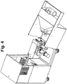
Fig. 1 , a compact shredder and compactor according to the present invention is shown. Metal chips to be compacted into briquettes are dumped in a chip box (A1) by e.g. a CNC machine conveyor or manually by person (not shown). A feed screw (A2) pushes the chips towards an opening in a cutter (seefigure 2 ) via a restrictor (A3) comprising a pipe like portion leading to the opening in the cutter. With reference toFigs. 2-4 , the cutter comprises a drive motor (B1) placed on one end of the cutter housing (B2) and driving a miller screw (B3), i.e. a screw providing both a cutting action and a transporting action for items having been cut, which shreds, or cuts, long chips into acquired size against a cutter plate (B4) fastened to the cutter housing. Chips in the desired size are then forced in the axial directing of the miller screw into a press chamber (C3). Once a desired amount of chips are gathered in the press chamber, the chips are compacted by a piston having a shape corresponding to the press chamber and being powered by e.g. a hydraulic piston (C1) arranged in one end of the press chamber. After the compression, a gate (C2) at an opposite end of the press chamber opens and compacted slugs are pushed out by the piston maneuvered by the hydraulic press piston (C1). - If any solid slug would block the miller screw (B3), a tilt cylinder (B5) will rotate the cutter housing (B2), such that the solid slug will not be engaged by the miller screw and the cutter plate and hence be rejectable, e.g. by the force of gravity once the cutter housing has rotated such that the opening points downwards. After the solid slug has been rejected, the cutter housing will be rotated back to its original position and the process can continue.
- One way of determining that a non-shreddable item has been stuck in the miller screw/shredder housing is to monitor the torque applied by the drive motor. This monitoring of the torque could be achieved e.g. by monitoring the drive current to the drive motor. If the applied torque exceeds a certain threshold value, the above sequence for rejecting a stuck item may be implemented.
- It is advantageous to be able to tilt, or rotate, the cutter housing if an item has stuck and blocks the miller screw; it is of course possible to reverse the direction of the miller screw in order to release the too large item having been stuck, but if the housing is not rotated, the restrictor (A3) comprising a pipe like portion leading to the opening in the cutter will stop the stuck item from being removed from its blocking position. Moreover, if the housing is rotated such that the opening faces downwards, gravity will help removing the stuck item.
- Preferably, the feed screw is shut off prior to the shredder housing being rotated in case of a stuck item requiring removal.
- In another embodiment of the invention, there is no tilt cylinder provided for rotating the cutter housing; instead, the rotation of the cutter housing is achieved by providing the housing on bearings allowing for rotation and a locking system enabling the cutter housing to be locked in desired positions. If an object has stuck, the locking system may release the cutter housing, Thereafter, the miller screw is rotated in the cutting direction, bringing the cutter housing with it. Once the cutter housing has reached the desired position, the cutter housing is locked and the miller screw is rotated in the opposite direction, i.e. the direction releasing the stuck item, such that the stuck item may be rejected.
- The system disclosed above and in the drawings can handle long or short chips and reject solid slugs that cannot be shredded and are too large for being transported into the press chamber. It is designed from beginning to do this with few parts in a compact package. This covers all possible working conditions and provides one stop shopping at attractive price. The compactness and price gives possibilities for small workshops to own a recycling system. This will give them much more money back per kilo of waste material. Cutting fluids will be fed back to manufacturing machine; this will provide a significant improvement on environmental issues. The fact that chips are compacted directly at the CNC machine will guarantee that no chips are wasted into nature; this is the biggest environmental profit. Every lost kilo of material must in the end be compensated by mining more from the earth. It's much more energy efficient to recycle material. Current system does not provide possibilities for the great mass of workshops to recycle their material in an efficient and economical way.
Claims (2)
- A shredder comprising:a shredder housing having an opening;a chip box (A1) comprising a restrictor (A3) with a pipe-like portion leading to said opening of the shredder housing;a feed screw (A2) configured to push items to be shredded and compacted towards said opening of the shredder housing via said restrictor (A3);a cutter housing (B2) having internal spiral grooves, wherein a miller screw (B3) is housed in said cutter housing (B2) and driven by a drive motor (B1), and wherein a cutter plate (B4) is fastened to said cutter housing (B2); anda press chamber (C3) configured to receive shredded items;said miller screw (B3) being configured to shred items to be shredded into the acquired size against said cutter plate (B4), and to force the shredded items into said press chamber (C3);said cutter housing (B2) being able to be rotated and reject solid slugs; andsaid chip box (A1) being able to be flipped up for easy cleaning access when changing alloys to be pressed.
- The shredder as claimed in claim 1, wherein chips are received radially in the shredder, and wherein the shredder redirects the chips axially and precompresses the chips in said press chamber (C3).
Applications Claiming Priority (2)
| Application Number | Priority Date | Filing Date | Title |
|---|---|---|---|
| SE1251260 | 2012-11-06 | ||
| PCT/SE2013/051303 WO2014074060A1 (en) | 2012-11-06 | 2013-11-06 | Compact shredder and compactor |
Publications (3)
| Publication Number | Publication Date |
|---|---|
| EP2916956A1 EP2916956A1 (en) | 2015-09-16 |
| EP2916956A4 EP2916956A4 (en) | 2016-07-13 |
| EP2916956B1 true EP2916956B1 (en) | 2020-04-29 |
Family
ID=50685002
Family Applications (1)
| Application Number | Title | Priority Date | Filing Date |
|---|---|---|---|
| EP13852866.6A Active EP2916956B1 (en) | 2012-11-06 | 2013-11-06 | Compact shredder and compactor |
Country Status (4)
| Country | Link |
|---|---|
| US (1) | US10532532B2 (en) |
| EP (1) | EP2916956B1 (en) |
| ES (1) | ES2802254T3 (en) |
| WO (1) | WO2014074060A1 (en) |
Families Citing this family (5)
| Publication number | Priority date | Publication date | Assignee | Title |
|---|---|---|---|---|
| EP2916956B1 (en) * | 2012-11-06 | 2020-04-29 | Danielsson Innovation AB | Compact shredder and compactor |
| JP6430956B2 (en) * | 2013-11-11 | 2018-11-28 | 加藤 進 | Crushing and explosion equipment and milling method |
| DE102018100595A1 (en) * | 2018-01-12 | 2019-07-18 | Bürener Maschinenfabrik GmbH | Device for processing chips |
| CN111331909B (en) * | 2018-06-21 | 2021-09-24 | 泉州台商投资区瑞诚文科技有限公司 | Volume reduction device for recycling waste pop cans and use method |
| SE547274C2 (en) * | 2024-02-16 | 2025-06-17 | Danielsson Innovation Ab | Self-feeding chip crusher |
Family Cites Families (23)
| Publication number | Priority date | Publication date | Assignee | Title |
|---|---|---|---|---|
| GB552868A (en) * | 1941-05-13 | 1900-01-01 | ||
| US3384138A (en) * | 1966-02-07 | 1968-05-21 | Int Harvester Co | Corn sheller and cob grinder |
| FR2230320B3 (en) * | 1973-05-23 | 1976-05-14 | Moulinex Sa | |
| US4056379A (en) * | 1977-01-03 | 1977-11-01 | Ppg Industries, Inc. | Forming V bends in glass sheets by press bending |
| DE2702653A1 (en) | 1977-01-24 | 1978-07-27 | Kloeckner Gmbh & Co Geb | Axial throughput refuse mill - has horizontal auger type grinding rotor with refuse fed tangentially from overhead hopper |
| US4157025A (en) * | 1977-12-05 | 1979-06-05 | Berezin Evgeny N | Method and mill for rolling metal billets |
| DE3036397A1 (en) * | 1980-09-26 | 1982-05-13 | Hermann Berstorff Maschinenbau Gmbh, 3000 Hannover | DEVICE FOR PREPARING POWDERED RUBBER MIXTURES |
| US4712641A (en) * | 1984-03-19 | 1987-12-15 | Bolt Technology Corporation | Method and system for generating shear waves and compression waves in the earth for seismic surveying |
| USRE33799E (en) * | 1984-11-08 | 1992-01-21 | Cylinder rupture vessel | |
| US5186219A (en) * | 1984-11-08 | 1993-02-16 | Earth Resources Consultants, Inc. | Cylinder rupture vessel |
| US4944333A (en) * | 1984-11-08 | 1990-07-31 | Earth Resources Consultants, Inc. | Cylinder rupture vessel with clamps for immobilizing a container inside the vessel |
| NO901836L (en) | 1989-04-28 | 1990-10-29 | Larry E Koenig | CONIC SPIRAL RIVER. |
| JP2955981B2 (en) * | 1995-04-28 | 1999-10-04 | サンマシーン株式会社 | Press equipment |
| JP3241247B2 (en) | 1995-11-24 | 2001-12-25 | 日立造船株式会社 | Screw type dust supply device |
| JPH10528A (en) | 1996-06-07 | 1998-01-06 | Hitachi Seiki Co Ltd | Chip disposal equipment |
| EP1196245A4 (en) * | 1999-02-04 | 2005-11-02 | Mct Holdings Llc | Shredder with parts ejector |
| US6588690B1 (en) * | 2000-03-14 | 2003-07-08 | Komar Industries, Inc. | System and method for treating process material |
| JP2002283175A (en) | 2001-03-27 | 2002-10-03 | Keiso Kogyo Kk | Chip compressing device |
| US7607600B2 (en) * | 2007-09-13 | 2009-10-27 | Martin Salgado | Meat shredder |
| KR101003630B1 (en) * | 2008-07-11 | 2010-12-23 | 전병우 | Vegetable Garbage Disposal Equipment |
| KR101092370B1 (en) | 2009-06-24 | 2011-12-09 | 한국생산기술연구원 | Apparatus for recycling metal cutting chip |
| KR20110101502A (en) * | 2010-03-08 | 2011-09-16 | 주식회사델리스 | Cookie Maker |
| EP2916956B1 (en) * | 2012-11-06 | 2020-04-29 | Danielsson Innovation AB | Compact shredder and compactor |
-
2013
- 2013-11-06 EP EP13852866.6A patent/EP2916956B1/en active Active
- 2013-11-06 WO PCT/SE2013/051303 patent/WO2014074060A1/en not_active Ceased
- 2013-11-06 ES ES13852866T patent/ES2802254T3/en active Active
- 2013-11-06 US US14/441,080 patent/US10532532B2/en active Active
Non-Patent Citations (1)
| Title |
|---|
| None * |
Also Published As
| Publication number | Publication date |
|---|---|
| EP2916956A4 (en) | 2016-07-13 |
| US10532532B2 (en) | 2020-01-14 |
| WO2014074060A1 (en) | 2014-05-15 |
| US20150290895A1 (en) | 2015-10-15 |
| EP2916956A1 (en) | 2015-09-16 |
| ES2802254T3 (en) | 2021-01-18 |
Similar Documents
| Publication | Publication Date | Title |
|---|---|---|
| US10532532B2 (en) | Compact shredder and compactor | |
| US7448318B1 (en) | Compacting apparatus | |
| KR101456074B1 (en) | The food garbage compactor and The food garbage processing apparatus | |
| CN204602783U (en) | Crushing machine | |
| JP6763516B2 (en) | Metal cuttings compression device | |
| US4917310A (en) | Processing apparatus for solid refuse | |
| CN113953884A (en) | Scrap collecting and processing device for metal structure machining | |
| US8882008B1 (en) | Dual shredding system for a mobile document shredding vehicle and method of use | |
| JPH05505558A (en) | device for crushing objects | |
| JP5620333B2 (en) | Pumping device | |
| CN211755694U (en) | Abandonment metal drum is with device that tears | |
| CN210585247U (en) | Metal filing smashing device | |
| JP4803793B2 (en) | Single screw crusher | |
| CN108032462A (en) | A kind of plastic film pulverizer | |
| FR2939702A1 (en) | PROCESS AND DEVICE FOR PROCESSING PRODUCTS FOR ROTATING | |
| EP1055459B1 (en) | Device for force feeding of plastic parts or waste elements of different sizes into all kinds of crushing machines | |
| KR101545522B1 (en) | Apparatus for crushing security documents | |
| JPH0957138A (en) | Single shaft crusher | |
| CN216800089U (en) | Gauze mask is cloth recovery unit for production and processing | |
| JP3200545B2 (en) | Single shaft crusher | |
| CN118321311A (en) | Metal chip shredding and extrusion machine | |
| KR102397836B1 (en) | Container direct coupling type waste processing system | |
| CN215353655U (en) | Categorised breaker of paper products | |
| CN201264800Y (en) | Vehicle for processing recovered materials | |
| KR101567505B1 (en) | Crushing method of scrap |
Legal Events
| Date | Code | Title | Description |
|---|---|---|---|
| PUAI | Public reference made under article 153(3) epc to a published international application that has entered the european phase |
Free format text: ORIGINAL CODE: 0009012 |
|
| 17P | Request for examination filed |
Effective date: 20150604 |
|
| AK | Designated contracting states |
Kind code of ref document: A1 Designated state(s): AL AT BE BG CH CY CZ DE DK EE ES FI FR GB GR HR HU IE IS IT LI LT LU LV MC MK MT NL NO PL PT RO RS SE SI SK SM TR |
|
| AX | Request for extension of the european patent |
Extension state: BA ME |
|
| DAX | Request for extension of the european patent (deleted) | ||
| RA4 | Supplementary search report drawn up and despatched (corrected) |
Effective date: 20160614 |
|
| RIC1 | Information provided on ipc code assigned before grant |
Ipc: B02C 23/02 20060101ALI20160608BHEP Ipc: B02C 19/22 20060101AFI20160608BHEP Ipc: C22B 1/248 20060101ALI20160608BHEP Ipc: B02C 17/10 20060101ALI20160608BHEP Ipc: B30B 9/32 20060101ALI20160608BHEP |
|
| STAA | Information on the status of an ep patent application or granted ep patent |
Free format text: STATUS: EXAMINATION IS IN PROGRESS |
|
| 17Q | First examination report despatched |
Effective date: 20190325 |
|
| GRAP | Despatch of communication of intention to grant a patent |
Free format text: ORIGINAL CODE: EPIDOSNIGR1 |
|
| STAA | Information on the status of an ep patent application or granted ep patent |
Free format text: STATUS: GRANT OF PATENT IS INTENDED |
|
| INTG | Intention to grant announced |
Effective date: 20191018 |
|
| GRAS | Grant fee paid |
Free format text: ORIGINAL CODE: EPIDOSNIGR3 |
|
| GRAJ | Information related to disapproval of communication of intention to grant by the applicant or resumption of examination proceedings by the epo deleted |
Free format text: ORIGINAL CODE: EPIDOSDIGR1 |
|
| GRAL | Information related to payment of fee for publishing/printing deleted |
Free format text: ORIGINAL CODE: EPIDOSDIGR3 |
|
| STAA | Information on the status of an ep patent application or granted ep patent |
Free format text: STATUS: EXAMINATION IS IN PROGRESS |
|
| GRAR | Information related to intention to grant a patent recorded |
Free format text: ORIGINAL CODE: EPIDOSNIGR71 |
|
| STAA | Information on the status of an ep patent application or granted ep patent |
Free format text: STATUS: GRANT OF PATENT IS INTENDED |
|
| INTC | Intention to grant announced (deleted) | ||
| GRAA | (expected) grant |
Free format text: ORIGINAL CODE: 0009210 |
|
| STAA | Information on the status of an ep patent application or granted ep patent |
Free format text: STATUS: THE PATENT HAS BEEN GRANTED |
|
| INTG | Intention to grant announced |
Effective date: 20200225 |
|
| AK | Designated contracting states |
Kind code of ref document: B1 Designated state(s): AL AT BE BG CH CY CZ DE DK EE ES FI FR GB GR HR HU IE IS IT LI LT LU LV MC MK MT NL NO PL PT RO RS SE SI SK SM TR |
|
| REG | Reference to a national code |
Ref country code: GB Ref legal event code: FG4D |
|
| REG | Reference to a national code |
Ref country code: CH Ref legal event code: EP |
|
| REG | Reference to a national code |
Ref country code: AT Ref legal event code: REF Ref document number: 1262501 Country of ref document: AT Kind code of ref document: T Effective date: 20200515 |
|
| REG | Reference to a national code |
Ref country code: DE Ref legal event code: R096 Ref document number: 602013068552 Country of ref document: DE |
|
| REG | Reference to a national code |
Ref country code: IE Ref legal event code: FG4D |
|
| REG | Reference to a national code |
Ref country code: SE Ref legal event code: TRGR |
|
| REG | Reference to a national code |
Ref country code: NL Ref legal event code: MP Effective date: 20200429 |
|
| REG | Reference to a national code |
Ref country code: LT Ref legal event code: MG4D |
|
| PG25 | Lapsed in a contracting state [announced via postgrant information from national office to epo] |
Ref country code: LT Free format text: LAPSE BECAUSE OF FAILURE TO SUBMIT A TRANSLATION OF THE DESCRIPTION OR TO PAY THE FEE WITHIN THE PRESCRIBED TIME-LIMIT Effective date: 20200429 Ref country code: PT Free format text: LAPSE BECAUSE OF FAILURE TO SUBMIT A TRANSLATION OF THE DESCRIPTION OR TO PAY THE FEE WITHIN THE PRESCRIBED TIME-LIMIT Effective date: 20200831 Ref country code: IS Free format text: LAPSE BECAUSE OF FAILURE TO SUBMIT A TRANSLATION OF THE DESCRIPTION OR TO PAY THE FEE WITHIN THE PRESCRIBED TIME-LIMIT Effective date: 20200829 Ref country code: NO Free format text: LAPSE BECAUSE OF FAILURE TO SUBMIT A TRANSLATION OF THE DESCRIPTION OR TO PAY THE FEE WITHIN THE PRESCRIBED TIME-LIMIT Effective date: 20200729 Ref country code: FI Free format text: LAPSE BECAUSE OF FAILURE TO SUBMIT A TRANSLATION OF THE DESCRIPTION OR TO PAY THE FEE WITHIN THE PRESCRIBED TIME-LIMIT Effective date: 20200429 Ref country code: GR Free format text: LAPSE BECAUSE OF FAILURE TO SUBMIT A TRANSLATION OF THE DESCRIPTION OR TO PAY THE FEE WITHIN THE PRESCRIBED TIME-LIMIT Effective date: 20200730 |
|
| REG | Reference to a national code |
Ref country code: AT Ref legal event code: MK05 Ref document number: 1262501 Country of ref document: AT Kind code of ref document: T Effective date: 20200429 |
|
| PG25 | Lapsed in a contracting state [announced via postgrant information from national office to epo] |
Ref country code: LV Free format text: LAPSE BECAUSE OF FAILURE TO SUBMIT A TRANSLATION OF THE DESCRIPTION OR TO PAY THE FEE WITHIN THE PRESCRIBED TIME-LIMIT Effective date: 20200429 Ref country code: HR Free format text: LAPSE BECAUSE OF FAILURE TO SUBMIT A TRANSLATION OF THE DESCRIPTION OR TO PAY THE FEE WITHIN THE PRESCRIBED TIME-LIMIT Effective date: 20200429 Ref country code: BG Free format text: LAPSE BECAUSE OF FAILURE TO SUBMIT A TRANSLATION OF THE DESCRIPTION OR TO PAY THE FEE WITHIN THE PRESCRIBED TIME-LIMIT Effective date: 20200729 Ref country code: RS Free format text: LAPSE BECAUSE OF FAILURE TO SUBMIT A TRANSLATION OF THE DESCRIPTION OR TO PAY THE FEE WITHIN THE PRESCRIBED TIME-LIMIT Effective date: 20200429 |
|
| PG25 | Lapsed in a contracting state [announced via postgrant information from national office to epo] |
Ref country code: NL Free format text: LAPSE BECAUSE OF FAILURE TO SUBMIT A TRANSLATION OF THE DESCRIPTION OR TO PAY THE FEE WITHIN THE PRESCRIBED TIME-LIMIT Effective date: 20200429 Ref country code: AL Free format text: LAPSE BECAUSE OF FAILURE TO SUBMIT A TRANSLATION OF THE DESCRIPTION OR TO PAY THE FEE WITHIN THE PRESCRIBED TIME-LIMIT Effective date: 20200429 |
|
| REG | Reference to a national code |
Ref country code: ES Ref legal event code: FG2A Ref document number: 2802254 Country of ref document: ES Kind code of ref document: T3 Effective date: 20210118 |
|
| PG25 | Lapsed in a contracting state [announced via postgrant information from national office to epo] |
Ref country code: RO Free format text: LAPSE BECAUSE OF FAILURE TO SUBMIT A TRANSLATION OF THE DESCRIPTION OR TO PAY THE FEE WITHIN THE PRESCRIBED TIME-LIMIT Effective date: 20200429 Ref country code: CZ Free format text: LAPSE BECAUSE OF FAILURE TO SUBMIT A TRANSLATION OF THE DESCRIPTION OR TO PAY THE FEE WITHIN THE PRESCRIBED TIME-LIMIT Effective date: 20200429 Ref country code: DK Free format text: LAPSE BECAUSE OF FAILURE TO SUBMIT A TRANSLATION OF THE DESCRIPTION OR TO PAY THE FEE WITHIN THE PRESCRIBED TIME-LIMIT Effective date: 20200429 Ref country code: SM Free format text: LAPSE BECAUSE OF FAILURE TO SUBMIT A TRANSLATION OF THE DESCRIPTION OR TO PAY THE FEE WITHIN THE PRESCRIBED TIME-LIMIT Effective date: 20200429 Ref country code: AT Free format text: LAPSE BECAUSE OF FAILURE TO SUBMIT A TRANSLATION OF THE DESCRIPTION OR TO PAY THE FEE WITHIN THE PRESCRIBED TIME-LIMIT Effective date: 20200429 Ref country code: EE Free format text: LAPSE BECAUSE OF FAILURE TO SUBMIT A TRANSLATION OF THE DESCRIPTION OR TO PAY THE FEE WITHIN THE PRESCRIBED TIME-LIMIT Effective date: 20200429 |
|
| REG | Reference to a national code |
Ref country code: DE Ref legal event code: R097 Ref document number: 602013068552 Country of ref document: DE |
|
| PG25 | Lapsed in a contracting state [announced via postgrant information from national office to epo] |
Ref country code: PL Free format text: LAPSE BECAUSE OF FAILURE TO SUBMIT A TRANSLATION OF THE DESCRIPTION OR TO PAY THE FEE WITHIN THE PRESCRIBED TIME-LIMIT Effective date: 20200429 Ref country code: SK Free format text: LAPSE BECAUSE OF FAILURE TO SUBMIT A TRANSLATION OF THE DESCRIPTION OR TO PAY THE FEE WITHIN THE PRESCRIBED TIME-LIMIT Effective date: 20200429 |
|
| PLBE | No opposition filed within time limit |
Free format text: ORIGINAL CODE: 0009261 |
|
| STAA | Information on the status of an ep patent application or granted ep patent |
Free format text: STATUS: NO OPPOSITION FILED WITHIN TIME LIMIT |
|
| 26N | No opposition filed |
Effective date: 20210201 |
|
| PG25 | Lapsed in a contracting state [announced via postgrant information from national office to epo] |
Ref country code: SI Free format text: LAPSE BECAUSE OF FAILURE TO SUBMIT A TRANSLATION OF THE DESCRIPTION OR TO PAY THE FEE WITHIN THE PRESCRIBED TIME-LIMIT Effective date: 20200429 |
|
| PG25 | Lapsed in a contracting state [announced via postgrant information from national office to epo] |
Ref country code: MC Free format text: LAPSE BECAUSE OF FAILURE TO SUBMIT A TRANSLATION OF THE DESCRIPTION OR TO PAY THE FEE WITHIN THE PRESCRIBED TIME-LIMIT Effective date: 20200429 |
|
| REG | Reference to a national code |
Ref country code: CH Ref legal event code: PL |
|
| PG25 | Lapsed in a contracting state [announced via postgrant information from national office to epo] |
Ref country code: LU Free format text: LAPSE BECAUSE OF NON-PAYMENT OF DUE FEES Effective date: 20201106 |
|
| REG | Reference to a national code |
Ref country code: BE Ref legal event code: MM Effective date: 20201130 |
|
| PG25 | Lapsed in a contracting state [announced via postgrant information from national office to epo] |
Ref country code: CH Free format text: LAPSE BECAUSE OF NON-PAYMENT OF DUE FEES Effective date: 20201130 Ref country code: LI Free format text: LAPSE BECAUSE OF NON-PAYMENT OF DUE FEES Effective date: 20201130 |
|
| PG25 | Lapsed in a contracting state [announced via postgrant information from national office to epo] |
Ref country code: IE Free format text: LAPSE BECAUSE OF NON-PAYMENT OF DUE FEES Effective date: 20201106 |
|
| PG25 | Lapsed in a contracting state [announced via postgrant information from national office to epo] |
Ref country code: TR Free format text: LAPSE BECAUSE OF FAILURE TO SUBMIT A TRANSLATION OF THE DESCRIPTION OR TO PAY THE FEE WITHIN THE PRESCRIBED TIME-LIMIT Effective date: 20200429 Ref country code: MT Free format text: LAPSE BECAUSE OF FAILURE TO SUBMIT A TRANSLATION OF THE DESCRIPTION OR TO PAY THE FEE WITHIN THE PRESCRIBED TIME-LIMIT Effective date: 20200429 Ref country code: CY Free format text: LAPSE BECAUSE OF FAILURE TO SUBMIT A TRANSLATION OF THE DESCRIPTION OR TO PAY THE FEE WITHIN THE PRESCRIBED TIME-LIMIT Effective date: 20200429 |
|
| PG25 | Lapsed in a contracting state [announced via postgrant information from national office to epo] |
Ref country code: MK Free format text: LAPSE BECAUSE OF FAILURE TO SUBMIT A TRANSLATION OF THE DESCRIPTION OR TO PAY THE FEE WITHIN THE PRESCRIBED TIME-LIMIT Effective date: 20200429 |
|
| PG25 | Lapsed in a contracting state [announced via postgrant information from national office to epo] |
Ref country code: BE Free format text: LAPSE BECAUSE OF NON-PAYMENT OF DUE FEES Effective date: 20201130 |
|
| P01 | Opt-out of the competence of the unified patent court (upc) registered |
Effective date: 20230508 |
|
| PGFP | Annual fee paid to national office [announced via postgrant information from national office to epo] |
Ref country code: DE Payment date: 20251121 Year of fee payment: 13 |
|
| PGFP | Annual fee paid to national office [announced via postgrant information from national office to epo] |
Ref country code: GB Payment date: 20251117 Year of fee payment: 13 |
|
| PGFP | Annual fee paid to national office [announced via postgrant information from national office to epo] |
Ref country code: IT Payment date: 20251029 Year of fee payment: 13 |
|
| PGFP | Annual fee paid to national office [announced via postgrant information from national office to epo] |
Ref country code: FR Payment date: 20251117 Year of fee payment: 13 |
|
| PGFP | Annual fee paid to national office [announced via postgrant information from national office to epo] |
Ref country code: SE Payment date: 20251118 Year of fee payment: 13 |
|
| PGFP | Annual fee paid to national office [announced via postgrant information from national office to epo] |
Ref country code: ES Payment date: 20251205 Year of fee payment: 13 |