EP2916372A1 - Conveyor apparatus - Google Patents
Conveyor apparatus Download PDFInfo
- Publication number
- EP2916372A1 EP2916372A1 EP13850408.9A EP13850408A EP2916372A1 EP 2916372 A1 EP2916372 A1 EP 2916372A1 EP 13850408 A EP13850408 A EP 13850408A EP 2916372 A1 EP2916372 A1 EP 2916372A1
- Authority
- EP
- European Patent Office
- Prior art keywords
- bagged electrode
- unit
- electrode
- bagged
- conveyor
- Prior art date
- Legal status (The legal status is an assumption and is not a legal conclusion. Google has not performed a legal analysis and makes no representation as to the accuracy of the status listed.)
- Granted
Links
Images

Classifications
-
- B—PERFORMING OPERATIONS; TRANSPORTING
- B65—CONVEYING; PACKING; STORING; HANDLING THIN OR FILAMENTARY MATERIAL
- B65G—TRANSPORT OR STORAGE DEVICES, e.g. CONVEYORS FOR LOADING OR TIPPING, SHOP CONVEYOR SYSTEMS OR PNEUMATIC TUBE CONVEYORS
- B65G49/00—Conveying systems characterised by their application for specified purposes not otherwise provided for
-
- B—PERFORMING OPERATIONS; TRANSPORTING
- B65—CONVEYING; PACKING; STORING; HANDLING THIN OR FILAMENTARY MATERIAL
- B65G—TRANSPORT OR STORAGE DEVICES, e.g. CONVEYORS FOR LOADING OR TIPPING, SHOP CONVEYOR SYSTEMS OR PNEUMATIC TUBE CONVEYORS
- B65G57/00—Stacking of articles
- B65G57/02—Stacking of articles by adding to the top of the stack
- B65G57/03—Stacking of articles by adding to the top of the stack from above
- B65G57/04—Stacking of articles by adding to the top of the stack from above by suction or magnetic devices
-
- H—ELECTRICITY
- H01—ELECTRIC ELEMENTS
- H01M—PROCESSES OR MEANS, e.g. BATTERIES, FOR THE DIRECT CONVERSION OF CHEMICAL ENERGY INTO ELECTRICAL ENERGY
- H01M10/00—Secondary cells; Manufacture thereof
- H01M10/04—Construction or manufacture in general
- H01M10/0404—Machines for assembling batteries
-
- H—ELECTRICITY
- H01—ELECTRIC ELEMENTS
- H01M—PROCESSES OR MEANS, e.g. BATTERIES, FOR THE DIRECT CONVERSION OF CHEMICAL ENERGY INTO ELECTRICAL ENERGY
- H01M50/00—Constructional details or processes of manufacture of the non-active parts of electrochemical cells other than fuel cells, e.g. hybrid cells
- H01M50/40—Separators; Membranes; Diaphragms; Spacing elements inside cells
- H01M50/46—Separators, membranes or diaphragms characterised by their combination with electrodes
-
- H—ELECTRICITY
- H01—ELECTRIC ELEMENTS
- H01M—PROCESSES OR MEANS, e.g. BATTERIES, FOR THE DIRECT CONVERSION OF CHEMICAL ENERGY INTO ELECTRICAL ENERGY
- H01M50/00—Constructional details or processes of manufacture of the non-active parts of electrochemical cells other than fuel cells, e.g. hybrid cells
- H01M50/40—Separators; Membranes; Diaphragms; Spacing elements inside cells
- H01M50/463—Separators, membranes or diaphragms characterised by their shape
- H01M50/466—U-shaped, bag-shaped or folded
-
- H—ELECTRICITY
- H01—ELECTRIC ELEMENTS
- H01M—PROCESSES OR MEANS, e.g. BATTERIES, FOR THE DIRECT CONVERSION OF CHEMICAL ENERGY INTO ELECTRICAL ENERGY
- H01M6/00—Primary cells; Manufacture thereof
- H01M6/005—Devices for making primary cells
-
- H—ELECTRICITY
- H05—ELECTRIC TECHNIQUES NOT OTHERWISE PROVIDED FOR
- H05F—STATIC ELECTRICITY; NATURALLY-OCCURRING ELECTRICITY
- H05F3/00—Carrying-off electrostatic charges
-
- Y—GENERAL TAGGING OF NEW TECHNOLOGICAL DEVELOPMENTS; GENERAL TAGGING OF CROSS-SECTIONAL TECHNOLOGIES SPANNING OVER SEVERAL SECTIONS OF THE IPC; TECHNICAL SUBJECTS COVERED BY FORMER USPC CROSS-REFERENCE ART COLLECTIONS [XRACs] AND DIGESTS
- Y02—TECHNOLOGIES OR APPLICATIONS FOR MITIGATION OR ADAPTATION AGAINST CLIMATE CHANGE
- Y02P—CLIMATE CHANGE MITIGATION TECHNOLOGIES IN THE PRODUCTION OR PROCESSING OF GOODS
- Y02P70/00—Climate change mitigation technologies in the production process for final industrial or consumer products
- Y02P70/50—Manufacturing or production processes characterised by the final manufactured product
Definitions
- the present invention relates to a conveyor apparatus that conveys a bagged electrode.
- an electric device formed by covering an electrode stack (a layered electrode unit) with a laminate sheet that is an outer packaging member.
- the electrode stack is formed by arranging positive and negative electrodes in layers through a separator.
- a bagged electrode (or a packaged electrode) obtained by packaging one of the positive and negative electrodes in a pair of separators is widely used.
- the bagged electrode obtained by packaging the positive electrode in the pair of separators and the negative electrode are alternately arranged in layers, then the electrode stack is formed.
- the bagged electrode is formed not by welding the whole circumference of the separator along four sides of the separator, but, in general, by partly welding the four sides of the separator (for instance, see Patent Document 1).
- Patent Document 1 Japanese Patent Provisional Publication Tokkai No. 7-302616
- the present invention was made to solve the above technical problem, and an object of the present invention is to provide a conveyor apparatus that is capable of performing the operation of the bagged electrode with the separator being in a non-expanding state.
- a conveyor apparatus of the present invention to achieve the above object conveys a bagged electrode that is formed by sandwiching an electrode by a pair of separators and by partly welding an outer circumference of the pair of separators.
- the conveyor apparatus has a conveyor unit, an operating unit and an air-blowing unit.
- the conveyor unit conveys the bagged electrode while holding the bagged electrode.
- the operating unit performs an operation of the exposed bagged electrode at a part of a conveyor line of the conveyor unit.
- the air-blowing unit blows toward a surface that is an opposite side to a held surface of the bagged electrode.
- a conveyor apparatus 1 according to a first embodiment will be explained with reference to Figs. 1 to 6D .
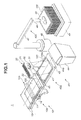
- Fig.1 is a perspective view showing the conveyor apparatus 1.
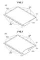
- Fig. 2 is a perspective view showing a bagged electrode (or a packaged electrode) 100 conveyed by the conveyor apparatus 1.
- Fig. 3 is a perspective view showing a bagged electrode 300 conveyed by a conveyor apparatus of a comparative example.
- Fig. 4 is a side view showing a defective bagged electrode 100 that is conveyed and rejected by the conveyor apparatus 1.
- Fig. 5 is a side view showing a defective bagged electrode 300 that is conveyed and rejected by the comparative example.
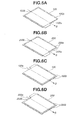
- Figs. 6A to 6D show a variety of bagged electrodes conveyed by the conveyor apparatus 1.
- the conveyor apparatus 1 has, as shown in Fig. 1 , a conveyor unit 10, an air-blowing unit 20 and an operating unit (a shooting unit 30 and a transferring unit 40).
- the conveyor apparatus 1 performs the operation of the bagged electrode 100 whose separator 120 is in a non-expanding state.
- the bagged electrode 100 conveyed by the conveyor apparatus 1 is formed by sandwiching an electrode 110 by a pair of separators 120 and 130 and by partly welding an outer circumference of the pair of separators 120 and 130.
- the conveyor unit 10 conveys the bagged electrode 100 while holding the bagged electrode 100.
- the conveyor unit 10 has opposing lower and upper belt conveyors 10a and 10b, and conveys the bagged electrode 100 while holding the bagged electrode 100 so as to sandwich the bagged electrode 100 between the lower and upper belt conveyors 10a and 10b.
- the lower belt conveyor 10a and the upper belt conveyor 10b each have a conveyor belt 11, a driving roller 12, a driven roller 13, a tension roller 14 and a pair of auxiliary rollers 15.
- the conveyor belt 11 is an endless belt, and the driving roller 12 is disposed at one end of an inner circumferential surface of the conveyor belt 11, and the driven roller 13 is disposed at the other end of the inner circumferential surface of the conveyor belt 11.
- the conveyor belt 11 is driven by rotation of the driving roller 12, and conveys the bagged electrode 100.
- the driving roller 12 is connected to a motor (not shown), and rotates at a predetermined rotation speed.
- the driven roller 13 is rotated by the rotation of the driving roller 12.
- the tension roller 14 is located at some midpoint between the driving roller 12 and the driven roller 13, and disposed at the inner circumferential surface of the conveyor belt 11.
- the pair of auxiliary rollers 15 are set so as to face the tension roller 14 and be made in contact with an outer circumferential surface of the conveyor belt 11.
- the pair of auxiliary rollers 15 are separate from each other along a drive direction of the conveyor belt 11.
- the tension roller 14 provides a constant tension to the conveyor belt 11.
- the conveyor belt 11 conveys the bagged electrode 100 by an
- the operating unit performs the operation of the exposed bagged electrode 100 at a part of a conveyor line of the conveyor unit 10.
- the operating unit is provided with at least one of the shooting unit 30 and the transferring unit 40. In the first embodiment, both of the shooting unit 30 and the transferring unit 40 are provided in the operating unit, and this case will be explained.
- the shooting unit 30 shoots the bagged electrode 100 fromaside facingaheldsurfaceof thebaggedelectrode 100.
- the held surf ace is, for instance, a surface, which faces the conveyor belt 11 mounting and conveying the bagged electrode 100, of the bagged electrode 100. More specifically, the held surface corresponds to a lower surface side of the lower separator 130 as shown in Fig. 2 .
- the shooting unit 30 is provided with a CCD camera 31, as shown in Fig. 1 .
- the CCD camera 31 shoots the bagged electrode 100 from above, and obtains an image of the bagged electrode 100.
- a resolution of the CCD camera 31 for instance, a resolution of a few tens of micrometers ( ⁇ m) ⁇ 1, mm is selected according to required measurement precision.
- the shooting unit 30 measures outer dimensions of the separator 120 from the image shot by the CCD camera 31 by a controller (not shown). Further, the shooting unit 30 can measure or sense a position of an edge portion of the electrode 110 through the separator 120 by the controller.
- the controller measures the outer dimensions of the separator 120, and if its measurement result falls within a predetermined specification range, the controller judges to be a pass.
- the controller judges to be a failure (or a rejection).
- the after-mentioned transferring unit 40 transfers the bagged electrode 100 so that, on the bases of the measurement result, a relative position of the bagged electrode 100, which is stacked, does not shift.
- the controller could be mounted inside the shooting unit 30, or might be provided externally.
- the transferring unit 40 transfers the bagged electrode 100 to a different position from the conveyor line of the conveyor unit 10.
- the transferring unit 40 is provided with at least one of amounting transfer section 40a and a suction transfer section 40b. In the first embodiment, both of the mounting transfer section 40a and the suction transfer section 40b are provided in the transferring unit 40, and this case will be explained.
- the mounting transfer section 40a transfers the bagged electrode 100 while mounting thereon the bagged electrode 100.
- the mounting transfer section 40a transfers the bagged electrode 100 that is judged to be the failure by the shooting unit 30 while mounting thereon the bagged electrode 100.
- the mounting transfer section 40a is provided at a downstream side in a conveying direction of the bagged electrode 100 with respect to the conveyor unit 10.
- the above mentioned shooting unit 30 and the after-mentioned air-blowing unit 20 are located above the mounting transfer section 40a.
- the mounting transfer section 40a has a transfer belt 41, a driving roller 42 and a driven roller 43.
- the transfer belt 41 is an endless belt
- the driving roller 42 is disposed at one end of an inner circumferential surface of the transfer belt 41
- the driven roller 43 is disposed at the other end of the inner circumferential surface of the transfer belt 41.
- the transfer belt 41 is driven by rotation of the driving roller 42, and conveys the bagged electrode 100.
- the driving roller 42 is connected to a motor (not shown), and rotates at a predetermined rotation speed.
- the driven roller 43 is rotated by the rotation of the driving roller 42.
- the mounting transfer section 40a is provided with an ejection chute 44.
- the ejection chute 44 corresponds to a storage unit.
- the ejection chute 44 has a slot 44a.
- the ejection chute 44 temporarily stores the bagged electrode 100 that is judged to be the failure by the shooting unit 30.
- the mounting transfer section 40a drives the transfer belt 41 and transfers the bagged electrode 100, then throws or drops the bagged electrode 100 into the ejection chute 44 from the slot 44a.
- the ejection chute 44 is made of, for instance, hard plastic, and is formed into a box shape.
- the slot 44a of the ejection chute 44 is located close to an end at a downstream side in the conveying direction of the transfer belt 41.
- the bagged electrode 100 temporarily stored in the ejection chute 44 is carried to a waste storage space at regular time intervals.
- the defective bagged electrode 100 conveyed and thrown into the ejection chute 44 by the conveyor apparatus 1 of the first embodiment, as shown in Fig. 2 , since an opening 100a of the bagged electrode 100 does not swell or expand, the defective bagged electrode 100 (the opening 100a) does not interfere with the slot 44a of the ejection chute 44 as shown in Fig. 4 .
- the defective bagged electrode 300 conveyed and rejected by the comparative example, as shown in Fig. 3 , since an opening 300a of the bagged electrode 300 swells or expands, the defective bagged electrode 300 (the opening 300a) interferes with and clogs the slot 44a of the ejection chute 44 as shown in Fig. 5 .
- the suction transfer section 40b transfers the bagged electrode 100 while sucking the bagged electrode 100.
- the suction transfer section 40b transfers the bagged electrode 100 that is judged to be the pass by the shooting unit 30 while sucking the bagged electrode 100.
- the suction transfer section 40b is provided at the downstream side in the conveying direction of the bagged electrode 100 with respect to the conveyor unit 10 so as to be adjacent to the mounting transfer section 40a.
- the suction transfer section 40b has a suction member 45, an expansion member (or a telescopic member) 46, a hanging rotation member 47, a supporting member 48 and a mounting stage 49.
- the suction member 45 has a plate shape, and is provided with a plurality of suction openings on a surface that touches or is made in contact with the bagged electrode 100.
- the telescopic member 46 is cylindrical in shape, and can extend and retract, for instance, by power of an air compressor (not shown).
- the telescopic member 46 is connected to an upper portion of the suction member 45.
- the hanging rotation member 47 is joined to an upper end of the telescopic member 46.
- the hanging rotation member 47 rotates with the supporting member 48 being a center, for instance, by power of a motor (not shown).
- the supporting member 48 is set on a floor surface, and rotatably supports the hanging rotation member 47.
- the mounting stage 49 temporarily mounts thereon a non-defective bagged electrode 100 while stacking the non-defective bagged electrode 100.
- the air-blowing unit 20 blows toward a surface that is an opposite side to the held surface of the bagged electrode 100.
- the held surface corresponds to the lower surface side of the lower separator 130 as shown in Fig. 2 . Therefore, the opposite surface to the held surface corresponds to an upper surface side of the separator 120 as shown in Fig. 2 , which is a surface that does not touch the electrode 110.
- the air-blowing unit 20 has, as shown in Fig. 1 , a blower fan 21 and an ionizer 22.
- the blower fan 21 is set above the transfer belt 41 so as to be adjacent to the CCD camera of the after-mentioned shooting unit 30.
- the blower fan 21 blows on the bagged electrode 100.
- the ionizer 22 corresponds to a static electricity removal unit.
- the ionizer 22 is provided, for instance, at the blower fan 21.
- the ionizer 22 generates ion in the air, and neutralizes static electricity in the air by the generated ion.
- FIG. 6A is a case where the bagged electrode 100 is arranged so that the opening 100a points to a downstream side in a conveying direction S, which is a case where the air enters a gap between the upper separator and the electrode from the opening 100a during the conveyance, then the upper separator is likely to swell or expand. That is, this case is a most suitable case to suppress the expansion of the upper separator of the bagged electrode 100 by using the air-blowing unit 20.
- Fig. 6B is a case where a bagged electrode 200 is arranged so that an opening 200a points to the downstream side in the conveying direction S.
- Fig. 6C is a case where the bagged electrode 100 is arranged so that the opening 100a points to an upstream side in the conveying direction S and also aweldingportion 100b is provided at the downstream side in the conveying direction S, which is a case where it is hard for the air to enter the gap between the upper separator and the electrode from the opening 100a during the conveyance, and the upper separator is unlikely to swell or expand. Even so, this case is a case where the expansion of the upper separator of the bagged electrode 100 can be suppressed by using the air-blowing unit 20.
- FIG. 6D is a case where the bagged electrode 200 is arranged so that the opening 200a points to the upstream side in the conveying direction S and also one welding portion 200b is provided at the downstream side in the conveying direction S and further one welding portion 200b is provided at the opening 200a.
- the bagged electrode 200 shown in Fig. 6D it is quite hard for the air to enter the gap between the upper separator and the electrode from the opening 200a during the conveyance, and the upper separator is most unlikely to swell or expand. Even so, this case is a case where the expansion of the upper separator of the bagged electrode 200 can be suppressed by using the air-blowing unit 20.
- the conveyor apparatus 1 conveys the bagged electrode 100 that is formed by sandwiching the electrode 110 by the pair of separators 12 0 , 13 0 and by partly welding the outer circumference of the pair of separators 120, 130.
- the conveyor apparatus 1 has the conveyor unit 10, the operating unit and the air-blowing unit 20.
- the conveyor unit 10 conveys the bagged electrode 100 while holding the bagged electrode 100.
- the operating unit performs the operation of the exposed bagged electrode 100 at a part of the conveyor line of the conveyor unit 10.
- the air-blowing unit 20 blows toward the surface that is the opposite side to the held surface of the bagged electrode 100.
- the air-blowing unit 20 blows toward the opposite surface to the held surface of the bagged electrode 100. Therefore, the operating unit can perform the operation of the bagged electrode 100 whose separator 120 is in the non-expanding state.
- the components disposed in the conveying process correspond to components that form the conveyor apparatus 1, components that are provided closed to the conveyor apparatus 1 and a side wall that separates off the conveyor apparatus 1.
- the conveyor apparatus 1 conveys the bagged electrode 100 with the separator 120 being in the non-expanding state, it is possible to avoid an occurrence of creases on the separator 120 etc.. As a consequence, quality of the bagged electrode 100 conveyed and undergoing the operation by the conveyor apparatus 1 can be improved.
- the operating unit could have at least one of the shooting unit 30 and the transferring unit 40.
- the shooting unit 30 shoots the bagged electrode 100 from the side facing the held surface of the bagged electrode 100.
- the transferring unit 40 transfers the bagged electrode 100 to the different position from the conveyor line of the conveyor unit 10.
- the shooting unit 30 can shoot the outer dimensions of the separator 120 with the separator 120 of the bagged electrode 100 being in the non-expanding state with great precision. Consequently, a non-defective rate of the bagged electrode 100 can be improved.
- the transferring unit 40 can transfer the bagged electrode 100 without interference with other components.
- the air-blowing unit 20 could have the static electricity removal unit.
- the static electricity removal unit removes static electricity charged to the bagged electrode 100 and static electricity existing in the air around the bagged electrode 100.
- the static electricity generated at the bagged electrode 100 during the conveyance of the bagged electrode 100 can be removed using the static electricity removal unit. That is, it is possible to prevent a hole or a crack from occurring or appearing on a surface of the separator 120 etc. of the bagged electrode 100 due to electrical discharge caused by the static electricity.
- the transferring unit 40 could have at least one of the mounting transfer section 40a and the suction transfer section 40b.
- the mounting transfer section 40a transfers the bagged electrode 100 while mounting thereon the bagged electrode 100.
- the suction transfer section 40b transfers the bagged electrode 100 while sucking the bagged electrode 100.
- the mounting transfer section 40a can transfer the bagged electrode 100 without the interference of the separator 120 with other components.
- the suction transfer section 40b can transfer the bagged electrode 100 while sufficiently sucking the separator 120 of the bagged electrode 100. That is, it is possible to prevent the non-defective bagged electrode 100 from falling when being transferred and sucked by the suction member 45, and prevent the operation of the conveyor apparatus 1 from stopping.
- the transferring unit 40 could have the ejection chute 44.
- the ejection chute 44 has the slot 44a, and temporarily stores the bagged electrode 100.
- the transferring unit 40 throws or drops the bagged electrode 100 into the ejection chute 44 from the slot 44a.
- the conveyor apparatus 1 having such configuration, since the opening 100a of the bagged electrode 100 is brought into the non-expanding state, it is possible to prevent the separator 120 of the bagged electrode 100 from being snagged on the slot 44a of the ejection chute 44. That is, it is possible to prevent the defective bagged electrode 100 from clogging the slot 44a of the ejection chute 44, and prevent the operation of the conveyor apparatus 1 from stopping.
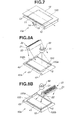
- Fig. 7 is a perspective view showing a main part of the conveyor apparatus according to the second embodiment.
- a shielding wall 16 is provided at the conveyor unit 10. This configuration is different from that of the conveyor apparatus 1 of the first embodiment described above.
- the same component or element as that of the first embodiment is denoted by the same reference sign, and overlapping explanation is omitted.
- the shielding wall 16 is provided at an upper side of the lower belt conveyor 10a, and the conveyor apparatus conveys the bagged electrode 100 by the lower belt conveyor 10a.
- the shielding wall 16 is arranged so as to cover the separator 120 of the conveyed bagged electrode 100.
- the air-blowing unit 20 blows on a shooting area of the shooting unit 30, and the conveyor unit 10 conveys the bagged electrode 100 while covering both surfaces of the bagged electrode 100 at an upstream side in the conveying direction of the bagged electrode 100 with respect to the shooting area.
- the conveyor apparatus having such configuration, since the air-blowing unit 20 blows only on the shooting area of the bagged electrode 100 shot by the shooting unit 30, a manufacturing cost associated with the air-blowing unit 20 can be suppressed, and also reduction in size of the conveyor apparatus 1 is possible. Further, since the both surfaces of the bagged electrode 100 are covered in an area where the bagged electrode is not shot by the shooting unit 30, the separator 120 of the bagged electrode 100 can be prevented from swelling or expanding.
- Figs. 8A and 8B are perspective views each showing a main part of the conveyor apparatus according to the third embodiment.
- the air-blowing unit 20 blows toward the downstream side or the upstream side in the conveying direction of the bagged electrode 100. This configuration is different from that of the conveyor apparatus 1 of the first embodiment described above.
- the same component or element as that of the first embodiment is denoted by the same reference sign, and overlapping explanation is omitted.
- the air-blowing unit 20 shown in Fig. 8A blows toward the downstream side in the conveying direction S of the bagged electrode 100. That is, the air-blowing unit 20 is arranged with the air-blowing unit 20 rotating by a predetermined angle in a counterclockwise direction with respect to a position of the air-blowing unit 20 shown in Fig. 1 .
- the conveyor unit 10 conveys the bagged electrode 100 with the opening 100a being positioned at the downstream side in the conveying direction of the bagged electrode 100. More specifically, this is applied to the bagged electrode 100 shown in Fig. 6A and the bagged electrode 200 shown in Fig. 6B .
- the air-blowing unit 20 blows from an opposite side to the opening 100a of the bagged electrode 100 to a direction toward the opening 100a.
- the air trapped in the bagged electrode 100 or the separator 120 can be expelled or released (or removed) effectively through the opening 100a or 200a.
- the air-blowing unit 20 shown in Fig. 8B blows toward the upstream side in the conveying direction S of the bagged electrode 100. That is, the air-blowing unit 20 is arranged with the air-blowing unit 20 rotating by a predetermined angle in a clockwise direction with respect to the position of the air-blowing unit 20 shown in Fig. 1 .
- the conveyor unit 10 conveys the bagged electrode 100 with the opening 100a being positioned at the upstream side in the conveying direction of the bagged electrode 100. More specifically, this is applied to the bagged electrode 100 shown in Fig. 6C and the bagged electrode 200 shown in Fig. 6D .
- the air-blowing unit 20 blows from an opposite side to the opening 100a of the bagged electrode 100 to a direction toward the opening 100a.
- the air trapped in the bagged electrode 100 or the separator 120 can be expelled or released (or removed) effectively through the opening 100a or 200a.
- the conveyor unit 10 conveys the bagged electrode 100 with the opening 100a being disposed (or positioned) at the downstream side or the upstream side in the conveying direction of the bagged electrode 100.
- the air-blowing unit 20 blows on the bagged electrode 100 whose opening 100a is positioned at the downstream side in the conveying direction toward the downstream side in the conveying direction of the bagged electrode 100.
- the air-blowing unit 2 0 could blow on the bagged electrode 100 whose opening 100a is positioned at the upstream side in the conveying direction toward the upstream side in the conveying direction of the bagged electrode 100.
- the conveyor apparatus having such configuration, for instance, in a case where the air is trapped or present between the electrode 110 and the separator 120, which form the bagged electrode 100, and the separator 120 swells or expands, the trapped air can be expelled or released (or removed) toward the opening 100a of the bagged electrode 100. That is, by blowing on the bagged electrode 100 from the opposite side to the opening 100a of the bagged electrode 100 to the direction toward the opening 100a, the air trapped in the bagged electrode 100 can be expelled or released (or removed) effectively from the opening 100a without being held trapped in the bagged electrode 100.
- the present invention includes all design modifications and equivalents belonging to the technical scope of the present invention.
- a manner of conveying the bagged electrode 100 is not limited to a belt-conveying manner. It could be a sucking manner. It is possible to employ a configuration that blows on the bagged electrode 100 from a lower side of the bagged electrode 100 while sucking the bagged electrode 100 from an upper side of the bagged electrode 100, in the conveyor unit 10.
- the non-defective bagged electrode 100 could be transferred while being mounted by a unit corresponding to the mounting transfer section 40a.
- the defective bagged electrode 100 could be transferred while being sucked by a unit corresponding to the suction transfer section 40b.
- the number of welding points and a welding position at the bagged electrode 100 are not especially limited. For instance, the welding portions could be provided only at the opposing two sides of the bagged electrode 100.
Landscapes
- General Chemical & Material Sciences (AREA)
- Chemical & Material Sciences (AREA)
- Chemical Kinetics & Catalysis (AREA)
- Electrochemistry (AREA)
- Engineering & Computer Science (AREA)
- Manufacturing & Machinery (AREA)
- Mechanical Engineering (AREA)
- Secondary Cells (AREA)
- Attitude Control For Articles On Conveyors (AREA)
- Containers And Plastic Fillers For Packaging (AREA)
- Cell Separators (AREA)
- Battery Electrode And Active Subsutance (AREA)
- Specific Conveyance Elements (AREA)
Abstract
Description
- The present invention relates to a conveyor apparatus that conveys a bagged electrode.
- In a related art, there has been an electric device formed by covering an electrode stack (a layered electrode unit) with a laminate sheet that is an outer packaging member. The electrode stack is formed by arranging positive and negative electrodes in layers through a separator.
- From the viewpoint of productivity of the electric device, a bagged electrode (or a packaged electrode) obtained by packaging one of the positive and negative electrodes in a pair of separators is widely used. For instance, the bagged electrode obtained by packaging the positive electrode in the pair of separators and the negative electrode are alternately arranged in layers, then the electrode stack is formed.
- Here, the bagged electrode is formed not by welding the whole circumference of the separator along four sides of the separator, but, in general, by partly welding the four sides of the separator (for instance, see Patent Document 1).
- Patent Document 1 : Japanese Patent Provisional Publication Tokkai No.
7-302616 - In a configuration of the
Patent Document 1, however, there is a cases where, when conveying the bagged electrode by a belt conveyor, air enters a gap between an upper separator of the pair of upper and lower separators and the electrode, then the upper separator swells or expands. The air enters the gap from a part of the separator where the upper and lower separators are not welded. When the bagged electrode is conveyed with the separator expanding and an operation is made to the bagged electrode, a desirable goal may not be achieved. - The present invention was made to solve the above technical problem, and an object of the present invention is to provide a conveyor apparatus that is capable of performing the operation of the bagged electrode with the separator being in a non-expanding state.
- A conveyor apparatus of the present invention to achieve the above object conveys a bagged electrode that is formed by sandwiching an electrode by a pair of separators and by partly welding an outer circumference of the pair of separators. The conveyor apparatus has a conveyor unit, an operating unit and an air-blowing unit. The conveyor unit conveys the bagged electrode while holding the bagged electrode. The operating unit performs an operation of the exposed bagged electrode at a part of a conveyor line of the conveyor unit. The air-blowing unit blows toward a surface that is an opposite side to a held surface of the bagged electrode.
-
- [
Fig. 1 ]
Fig. 1 is a perspective view showing a conveyor apparatus according to a first embodiment. - [
Fig. 2 ]
Fig.2 is a perspective view showing a bagged electrode conveyed by the conveyor apparatus of the first embodiment. - [
Fig. 3 ]
Fig. 3 is a perspective view showing a bagged electrode conveyed by a conveyor apparatus of a comparative example. - [
Fig. 4 ]
Fig. 4 is a side view showing a defective bagged electrode that is conveyed and rejected by the conveyor apparatus of the first embodiment. - [
Fig. 5 ]
Fig. 5 is a side view showing a defective bagged electrode that is conveyed and rejected by the comparative example. - [
Fig. 6 ]
Figs. 6A to 6D show a variety of bagged electrodes conveyed by the conveyor apparatus of the first embodiment. - [
Fig. 7 ]
Fig. 7 is a perspective view showing a main part of a conveyor apparatus according to a second embodiment. - [
Fig. 8 ]
Figs. 8A and 8B are perspective views each showing a main part of a conveyor apparatus according to a third embodiment. - In the following description, first to third embodiments of the present invention will be explained with reference to the drawings. In the explanation of the drawings, the same element or component is denoted by the same reference sign, and overlapping explanation is omitted. For convenience in explanation, a size or a ratio of each element or component in the drawings might be different from an actual size or an actual ratio.
- A
conveyor apparatus 1 according to a first embodiment will be explained with reference toFigs. 1 to 6D . -
Fig.1 is a perspective view showing theconveyor apparatus 1.Fig. 2 is a perspective view showing a bagged electrode (or a packaged electrode) 100 conveyed by theconveyor apparatus 1.Fig. 3 is a perspective view showing abagged electrode 300 conveyed by a conveyor apparatus of a comparative example.Fig. 4 is a side view showing a defectivebagged electrode 100 that is conveyed and rejected by theconveyor apparatus 1.Fig. 5 is a side view showing a defectivebagged electrode 300 that is conveyed and rejected by the comparative example.Figs. 6A to 6D show a variety of bagged electrodes conveyed by theconveyor apparatus 1. - The
conveyor apparatus 1 has, as shown inFig. 1 , aconveyor unit 10, an air-blowingunit 20 and an operating unit (ashooting unit 30 and a transferring unit 40). Theconveyor apparatus 1 performs the operation of thebagged electrode 100 whoseseparator 120 is in a non-expanding state. Thebagged electrode 100 conveyed by theconveyor apparatus 1 is formed by sandwiching anelectrode 110 by a pair ofseparators separators - The
conveyor unit 10 conveys thebagged electrode 100 while holding thebagged electrode 100. - As shown in
Fig. 1 , theconveyor unit 10 has opposing lower andupper belt conveyors bagged electrode 100 while holding thebagged electrode 100 so as to sandwich thebagged electrode 100 between the lower andupper belt conveyors lower belt conveyor 10a and theupper belt conveyor 10b each have aconveyor belt 11, adriving roller 12, a drivenroller 13, atension roller 14 and a pair ofauxiliary rollers 15. - The
conveyor belt 11 is an endless belt, and thedriving roller 12 is disposed at one end of an inner circumferential surface of theconveyor belt 11, and the drivenroller 13 is disposed at the other end of the inner circumferential surface of theconveyor belt 11. Theconveyor belt 11 is driven by rotation of thedriving roller 12, and conveys thebagged electrode 100. Thedriving roller 12 is connected to a motor (not shown), and rotates at a predetermined rotation speed. The drivenroller 13 is rotated by the rotation of thedriving roller 12. Thetension roller 14 is located at some midpoint between thedriving roller 12 and the drivenroller 13, and disposed at the inner circumferential surface of theconveyor belt 11. The pair ofauxiliary rollers 15 are set so as to face thetension roller 14 and be made in contact with an outer circumferential surface of theconveyor belt 11. The pair ofauxiliary rollers 15 are separate from each other along a drive direction of theconveyor belt 11. Thetension roller 14 provides a constant tension to theconveyor belt 11. Theconveyor belt 11 conveys the baggedelectrode 100 by an area where thetension roller 14 is not disposed. - The operating unit performs the operation of the exposed bagged
electrode 100 at a part of a conveyor line of theconveyor unit 10. The operating unit is provided with at least one of theshooting unit 30 and the transferringunit 40. In the first embodiment, both of theshooting unit 30 and the transferringunit 40 are provided in the operating unit, and this case will be explained. - The
shooting unit 30 shoots the baggedelectrode 100 fromaside facingaheldsurfaceof thebaggedelectrode 100. - The held surf ace is, for instance, a surface, which faces the
conveyor belt 11 mounting and conveying the baggedelectrode 100, of the baggedelectrode 100. More specifically, the held surface corresponds to a lower surface side of thelower separator 130 as shown inFig. 2 . - The
shooting unit 30 is provided with aCCD camera 31, as shown inFig. 1 . TheCCD camera 31 shoots the baggedelectrode 100 from above, and obtains an image of the baggedelectrode 100. As a resolution of theCCD camera 31, for instance, a resolution of a few tens of micrometers (µm) ∼ 1, mm is selected according to required measurement precision. Theshooting unit 30 measures outer dimensions of theseparator 120 from the image shot by theCCD camera 31 by a controller (not shown). Further, theshooting unit 30 can measure or sense a position of an edge portion of theelectrode 110 through theseparator 120 by the controller. The controller measures the outer dimensions of theseparator 120, and if its measurement result falls within a predetermined specification range, the controller judges to be a pass. On the other hand, if the measurement result is out of the predetermined specification range, the controller judges to be a failure (or a rejection). In a case where the controller measures or senses the position of the edge portion of theelectrode 110 of the baggedelectrode 100, the after-mentionedtransferring unit 40 transfers the baggedelectrode 100 so that, on the bases of the measurement result, a relative position of the baggedelectrode 100, which is stacked, does not shift. The controller could be mounted inside theshooting unit 30, or might be provided externally. - The transferring
unit 40 transfers the baggedelectrode 100 to a different position from the conveyor line of theconveyor unit 10. The transferringunit 40 is provided with at least one of amountingtransfer section 40a and a suction transfer section 40b. In the first embodiment, both of the mountingtransfer section 40a and the suction transfer section 40b are provided in the transferringunit 40, and this case will be explained. - The mounting
transfer section 40a transfers the baggedelectrode 100 while mounting thereon the baggedelectrode 100. - For instance, as shown in
Fig. 1 , the mountingtransfer section 40a transfers the baggedelectrode 100 that is judged to be the failure by theshooting unit 30 while mounting thereon the baggedelectrode 100. The mountingtransfer section 40a is provided at a downstream side in a conveying direction of the baggedelectrode 100 with respect to theconveyor unit 10. The above mentionedshooting unit 30 and the after-mentioned air-blowingunit 20 are located above the mountingtransfer section 40a. The mountingtransfer section 40a has atransfer belt 41, a drivingroller 42 and a drivenroller 43. Thetransfer belt 41 is an endless belt, and the drivingroller 42 is disposed at one end of an inner circumferential surface of thetransfer belt 41, and the drivenroller 43 is disposed at the other end of the inner circumferential surface of thetransfer belt 41. Thetransfer belt 41 is driven by rotation of the drivingroller 42, and conveys the baggedelectrode 100. The drivingroller 42 is connected to a motor (not shown), and rotates at a predetermined rotation speed. The drivenroller 43 is rotated by the rotation of the drivingroller 42. - The mounting
transfer section 40a is provided with anejection chute 44. Theejection chute 44 corresponds to a storage unit. Theejection chute 44 has aslot 44a. For instance, theejection chute 44 temporarily stores the baggedelectrode 100 that is judged to be the failure by theshooting unit 30. The mountingtransfer section 40a drives thetransfer belt 41 and transfers the baggedelectrode 100, then throws or drops the baggedelectrode 100 into theejection chute 44 from theslot 44a. Theejection chute 44 is made of, for instance, hard plastic, and is formed into a box shape. Theslot 44a of theejection chute 44 is located close to an end at a downstream side in the conveying direction of thetransfer belt 41. The baggedelectrode 100 temporarily stored in theejection chute 44 is carried to a waste storage space at regular time intervals. - Regarding the defective bagged
electrode 100 conveyed and thrown into theejection chute 44 by theconveyor apparatus 1 of the first embodiment, as shown inFig. 2 , since anopening 100a of the baggedelectrode 100 does not swell or expand, the defective bagged electrode 100 (theopening 100a) does not interfere with theslot 44a of theejection chute 44 as shown inFig. 4 . On the other hand, regarding the defective baggedelectrode 300 conveyed and rejected by the comparative example, as shown inFig. 3 , since anopening 300a of the baggedelectrode 300 swells or expands, the defective bagged electrode 300 (theopening 300a) interferes with and clogs theslot 44a of theejection chute 44 as shown inFig. 5 . - The suction transfer section 40b transfers the bagged
electrode 100 while sucking the baggedelectrode 100. - For instance, as shown in
Fig. 1 , the suction transfer section 40b transfers the baggedelectrode 100 that is judged to be the pass by theshooting unit 30 while sucking the baggedelectrode 100. The suction transfer section 40b is provided at the downstream side in the conveying direction of the baggedelectrode 100 with respect to theconveyor unit 10 so as to be adjacent to the mountingtransfer section 40a. The suction transfer section 40b has asuction member 45, an expansion member (or a telescopic member) 46, a hangingrotation member 47, a supportingmember 48 and a mountingstage 49. Thesuction member 45 has a plate shape, and is provided with a plurality of suction openings on a surface that touches or is made in contact with the baggedelectrode 100. Thetelescopic member 46 is cylindrical in shape, and can extend and retract, for instance, by power of an air compressor (not shown). Thetelescopic member 46 is connected to an upper portion of thesuction member 45. The hangingrotation member 47 is joined to an upper end of thetelescopic member 46. The hangingrotation member 47 rotates with the supportingmember 48 being a center, for instance, by power of a motor (not shown). The supportingmember 48 is set on a floor surface, and rotatably supports the hangingrotation member 47. The mountingstage 49 temporarily mounts thereon a non-defective baggedelectrode 100 while stacking the non-defective baggedelectrode 100. - The air-blowing
unit 20 blows toward a surface that is an opposite side to the held surface of the baggedelectrode 100. - As mentioned above, the held surface corresponds to the lower surface side of the
lower separator 130 as shown inFig. 2 . Therefore, the opposite surface to the held surface corresponds to an upper surface side of theseparator 120 as shown inFig. 2 , which is a surface that does not touch theelectrode 110. - The air-blowing
unit 20 has, as shown inFig. 1 , ablower fan 21 and anionizer 22. Theblower fan 21 is set above thetransfer belt 41 so as to be adjacent to the CCD camera of the after-mentionedshooting unit 30. Theblower fan 21 blows on the baggedelectrode 100. Theionizer 22 corresponds to a static electricity removal unit. Theionizer 22 is provided, for instance, at theblower fan 21. Theionizer 22 generates ion in the air, and neutralizes static electricity in the air by the generated ion. - A variety of bagged electrodes conveyed by the
conveyor apparatus 1 are shown inFigs. 6A to 6D. Fig. 6A is a case where the baggedelectrode 100 is arranged so that theopening 100a points to a downstream side in a conveying direction S, which is a case where the air enters a gap between the upper separator and the electrode from theopening 100a during the conveyance, then the upper separator is likely to swell or expand. That is, this case is a most suitable case to suppress the expansion of the upper separator of the baggedelectrode 100 by using the air-blowingunit 20.Fig. 6B is a case where a baggedelectrode 200 is arranged so that anopening 200a points to the downstream side in the conveying direction S. However, since onewelding portion 200b is provided at theopening 200a, it is hard for the air to enter the gap between the upper separator and the electrode from theopening 200a during the conveyance, and the upper separator is unlikely to swell or expand. Even so, this case is a case where the expansion of the upper separator of the baggedelectrode 200 can be suppressed by using the air-blowingunit 20. -
Fig. 6C is a case where the baggedelectrode 100 is arranged so that theopening 100a points to an upstream side in the conveying direction S and also aweldingportion 100b is provided at the downstream side in the conveying direction S, which is a case where it is hard for the air to enter the gap between the upper separator and the electrode from theopening 100a during the conveyance, and the upper separator is unlikely to swell or expand. Even so, this case is a case where the expansion of the upper separator of the baggedelectrode 100 can be suppressed by using the air-blowingunit 20.Fig. 6D is a case where the baggedelectrode 200 is arranged so that theopening 200a points to the upstream side in the conveying direction S and also onewelding portion 200b is provided at the downstream side in the conveying direction S and further onewelding portion 200b is provided at theopening 200a. For this reason, in the case of the baggedelectrode 200 shown inFig. 6D , it is quite hard for the air to enter the gap between the upper separator and the electrode from theopening 200a during the conveyance, and the upper separator is most unlikely to swell or expand. Even so, this case is a case where the expansion of the upper separator of the baggedelectrode 200 can be suppressed by using the air-blowingunit 20. - According to the
conveyor apparatus 1 of the first embodiment described above, the following operation and effect are obtained. - The
conveyor apparatus 1 conveys the baggedelectrode 100 that is formed by sandwiching theelectrode 110 by the pair ofseparators 12 0 , 13 0 and by partly welding the outer circumference of the pair ofseparators conveyor apparatus 1 has theconveyor unit 10, the operating unit and the air-blowingunit 20. Theconveyor unit 10 conveys the baggedelectrode 100 while holding the baggedelectrode 100. The operating unit performs the operation of the exposed baggedelectrode 100 at a part of the conveyor line of theconveyor unit 10. The air-blowingunit 20 blows toward the surface that is the opposite side to the held surface of the baggedelectrode 100. - According to the
conveyor apparatus 1 having such configuration, the air-blowingunit 20 blows toward the opposite surface to the held surface of the baggedelectrode 100. Therefore, the operating unit can perform the operation of the baggedelectrode 100 whoseseparator 120 is in the non-expanding state. - Further, with this configuration, since the
electrode 110 and theseparator 120, which form the baggedelectrode 100, are brought into intimate contact with each other by the blow, it is possible to prevent theseparator 120 from interfering with components disposed in a conveying process. Thus, an operating rate of the conveyance of the baggedelectrode 100 by theconveyor apparatus 1 can be improved. The components disposed in the conveying process correspond to components that form theconveyor apparatus 1, components that are provided closed to theconveyor apparatus 1 and a side wall that separates off theconveyor apparatus 1. - Moreover, with this configuration, since the
conveyor apparatus 1 conveys the baggedelectrode 100 with theseparator 120 being in the non-expanding state, it is possible to avoid an occurrence of creases on theseparator 120 etc.. As a consequence, quality of the baggedelectrode 100 conveyed and undergoing the operation by theconveyor apparatus 1 can be improved. - The operating unit could have at least one of the
shooting unit 30 and the transferringunit 40. Theshooting unit 30 shoots the baggedelectrode 100 from the side facing the held surface of the baggedelectrode 100. The transferringunit 40 transfers the baggedelectrode 100 to the different position from the conveyor line of theconveyor unit 10. - According to the
conveyor apparatus 1 having such configuration, theshooting unit 30 can shoot the outer dimensions of theseparator 120 with theseparator 120 of the baggedelectrode 100 being in the non-expanding state with great precision. Consequently, a non-defective rate of the baggedelectrode 100 can be improved. On the other hand, since theopening 100a of the baggedelectrode 100 is in the non-expanding state when being conveyed, the transferringunit 40 can transfer the baggedelectrode 100 without interference with other components. - The air-blowing
unit 20 could have the static electricity removal unit. The static electricity removal unit removes static electricity charged to the baggedelectrode 100 and static electricity existing in the air around the baggedelectrode 100. - According to the
conveyor apparatus 1 having such configuration, the static electricity generated at the baggedelectrode 100 during the conveyance of the baggedelectrode 100 can be removed using the static electricity removal unit. That is, it is possible to prevent a hole or a crack from occurring or appearing on a surface of theseparator 120 etc. of the baggedelectrode 100 due to electrical discharge caused by the static electricity. - The transferring
unit 40 could have at least one of the mountingtransfer section 40a and the suction transfer section 40b. The mountingtransfer section 40a transfers the baggedelectrode 100 while mounting thereon the baggedelectrode 100. The suction transfer section 40b transfers the baggedelectrode 100 while sucking the baggedelectrode 100. - According to the
conveyor apparatus 1 having such configuration, since theopening 100a of the baggedelectrode 100 is brought into the non-expanding state during the transfer of the baggedelectrode 100, the mountingtransfer section 40a can transfer the baggedelectrode 100 without the interference of theseparator 120 with other components. On the other hand, since theopening 100a of the baggedelectrode 100 is brought into the non-expanding state, the suction transfer section 40b can transfer the baggedelectrode 100 while sufficiently sucking theseparator 120 of the baggedelectrode 100. That is, it is possible to prevent the non-defective baggedelectrode 100 from falling when being transferred and sucked by thesuction member 45, and prevent the operation of theconveyor apparatus 1 from stopping. - The transferring
unit 40 could have theejection chute 44. Theejection chute 44 has theslot 44a, and temporarily stores the baggedelectrode 100. The transferringunit 40 throws or drops the baggedelectrode 100 into theejection chute 44 from theslot 44a. - According to the
conveyor apparatus 1 having such configuration, since theopening 100a of the baggedelectrode 100 is brought into the non-expanding state, it is possible to prevent theseparator 120 of the baggedelectrode 100 from being snagged on theslot 44a of theejection chute 44. That is, it is possible to prevent the defective baggedelectrode 100 from clogging theslot 44a of theejection chute 44, and prevent the operation of theconveyor apparatus 1 from stopping. - The conveyor apparatus according to a second embodiment will be explained with reference to
Fig. 7 . -
Fig. 7 is a perspective view showing a main part of the conveyor apparatus according to the second embodiment. - In the conveyor apparatus of the second embodiment, a shielding
wall 16 is provided at theconveyor unit 10. This configuration is different from that of theconveyor apparatus 1 of the first embodiment described above. - In the second embodiment, the same component or element as that of the first embodiment is denoted by the same reference sign, and overlapping explanation is omitted.
- As shown in
Fig. 7 , instead of the pair of lower andupper belt conveyors wall 16 is provided at an upper side of thelower belt conveyor 10a, and the conveyor apparatus conveys the baggedelectrode 100 by thelower belt conveyor 10a. The shieldingwall 16 is arranged so as to cover theseparator 120 of the conveyed baggedelectrode 100. - According to the conveyor apparatus of the second embodiment, in addition to the effect of the first embodiment, the following operation and effect are further obtained.
- In the configuration of the second embodiment, the air-blowing
unit 20 blows on a shooting area of theshooting unit 30, and theconveyor unit 10 conveys the baggedelectrode 100 while covering both surfaces of the baggedelectrode 100 at an upstream side in the conveying direction of the baggedelectrode 100 with respect to the shooting area. - According to the conveyor apparatus having such configuration, since the air-blowing
unit 20 blows only on the shooting area of the baggedelectrode 100 shot by theshooting unit 30, a manufacturing cost associated with the air-blowingunit 20 can be suppressed, and also reduction in size of theconveyor apparatus 1 is possible. Further, since the both surfaces of the baggedelectrode 100 are covered in an area where the bagged electrode is not shot by theshooting unit 30, theseparator 120 of the baggedelectrode 100 can be prevented from swelling or expanding. - In the conveyor apparatus of the second embodiment, in order to greatly simplify the configuration of the
conveyor unit 10 in an area except the shooting area shot by theshooting unit 30, only the shieldingwall 16 is provided over the baggedelectrode 100. Thus, the same effects as those of theconveyor apparatus 1 of the first embodiment described above can be obtained. - The conveyor apparatus according to a third embodiment will be explained with reference to
Figs. 8A and 8B . -
Figs. 8A and 8B are perspective views each showing a main part of the conveyor apparatus according to the third embodiment. - In the conveyor apparatus of the third embodiment, the air-blowing
unit 20 blows toward the downstream side or the upstream side in the conveying direction of the baggedelectrode 100. This configuration is different from that of theconveyor apparatus 1 of the first embodiment described above. - In the third embodiment, the same component or element as that of the first embodiment is denoted by the same reference sign, and overlapping explanation is omitted.
- In the conveyor apparatus, the air-blowing
unit 20 shown inFig. 8A blows toward the downstream side in the conveying direction S of the baggedelectrode 100. That is, the air-blowingunit 20 is arranged with the air-blowingunit 20 rotating by a predetermined angle in a counterclockwise direction with respect to a position of the air-blowingunit 20 shown inFig. 1 . In a case of this arrangement of the air-blowingunit 20, theconveyor unit 10 conveys the baggedelectrode 100 with theopening 100a being positioned at the downstream side in the conveying direction of the baggedelectrode 100. More specifically, this is applied to the baggedelectrode 100 shown inFig. 6A and the baggedelectrode 200 shown inFig. 6B . That is, for instance, the air-blowingunit 20 blows from an opposite side to theopening 100a of the baggedelectrode 100 to a direction toward theopening 100a. With this configuration or arrangement, the air trapped in the baggedelectrode 100 or theseparator 120 can be expelled or released (or removed) effectively through theopening - On the other hand, the air-blowing
unit 20 shown inFig. 8B blows toward the upstream side in the conveying direction S of the baggedelectrode 100. That is, the air-blowingunit 20 is arranged with the air-blowingunit 20 rotating by a predetermined angle in a clockwise direction with respect to the position of the air-blowingunit 20 shown inFig. 1 . In a case of this arrangement of the air-blowingunit 20, theconveyor unit 10 conveys the baggedelectrode 100 with theopening 100a being positioned at the upstream side in the conveying direction of the baggedelectrode 100. More specifically, this is applied to the baggedelectrode 100 shown inFig. 6C and the baggedelectrode 200 shown inFig. 6D . That is, for instance, the air-blowingunit 20 blows from an opposite side to theopening 100a of the baggedelectrode 100 to a direction toward theopening 100a. With this configuration or arrangement, the air trapped in the baggedelectrode 100 or theseparator 120 can be expelled or released (or removed) effectively through theopening - According to the conveyor apparatus of the third embodiment, in addition to the effects of the first embodiment and the second embodiment, the following operation and effect are further obtained.
- The
conveyor unit 10 conveys the baggedelectrode 100 with theopening 100a being disposed (or positioned) at the downstream side or the upstream side in the conveying direction of the baggedelectrode 100. The air-blowingunit 20 blows on the baggedelectrode 100 whoseopening 100a is positioned at the downstream side in the conveying direction toward the downstream side in the conveying direction of the baggedelectrode 100. On the other hand, the air-blowing unit 2 0 could blow on the baggedelectrode 100 whoseopening 100a is positioned at the upstream side in the conveying direction toward the upstream side in the conveying direction of the baggedelectrode 100. - According to the conveyor apparatus having such configuration, for instance, in a case where the air is trapped or present between the
electrode 110 and theseparator 120, which form the baggedelectrode 100, and theseparator 120 swells or expands, the trapped air can be expelled or released (or removed) toward theopening 100a of the baggedelectrode 100. That is, by blowing on the baggedelectrode 100 from the opposite side to theopening 100a of the baggedelectrode 100 to the direction toward theopening 100a, the air trapped in the baggedelectrode 100 can be expelled or released (or removed) effectively from theopening 100a without being held trapped in the baggedelectrode 100. - In addition to the above embodiments, the present invention includes all design modifications and equivalents belonging to the technical scope of the present invention.
- For instance, a manner of conveying the bagged
electrode 100 is not limited to a belt-conveying manner. It could be a sucking manner. It is possible to employ a configuration that blows on the baggedelectrode 100 from a lower side of the baggedelectrode 100 while sucking the baggedelectrode 100 from an upper side of the baggedelectrode 100, in theconveyor unit 10.
The non-defective baggedelectrode 100 could be transferred while being mounted by a unit corresponding to the mountingtransfer section 40a. The defective baggedelectrode 100 could be transferred while being sucked by a unit corresponding to the suction transfer section 40b. The number of welding points and a welding position at the baggedelectrode 100 are not especially limited. For instance, the welding portions could be provided only at the opposing two sides of the baggedelectrode 100. - This application is based on a prior Japanese Patent Application No.
2012-239481 filed on October 30, 2012 2012-239481 -
- 1
- conveyor apparatus
- 10
- conveyor unit
- 10a
- lower belt conveyor
- 10b
- upper belt conveyor
- 11
- conveyor belt
- 12
- driving roller
- 13
- driven roller
- 14
- tension roller
- 15
- auxiliary roller
- 16
- shielding wall
- 20
- air-blowing unit
- 21
- blower fan
- 22
- ionizer (corresponding to static electricity removal unit)
- 30
- shooting unit (one example of operating unit)
- 31
- camera
- 40
- transferring unit (the other example of operating unit)
- 40a
- mounting transfer section
- 40b
- suction transfer section
- 41
- transfer belt
- 42
- driving roller
- 43
- driven roller
- 44
- ejection chute (corresponding to storage unit)
- 44a
- slot
- 45
- suction member
- 46
- expansion member
- 47
- hanging rotation member
- 48
- supporting member
- 49
- mounting stage
- 100, 200, 300
- bagged electrode
- 100a, 200a, 300a
- opening
- 100b, 200b, 300b
- welding portion
- 110
- electrode
- 120, 130
- separator
Claims (7)
- A conveyor apparatus conveying a bagged electrode that is formed by sandwiching an electrode by a pair of separators and by partly welding an outer circumference of the pair of separators, the conveyor apparatus comprising:a conveyor unit conveying the bagged electrode while holding the bagged electrode;an operating unit performing an operation of the exposed bagged electrode at a part of a conveyor line of the conveyor unit; andan air-blowing unit blowing toward a surface that is an opposite side to a held surface of the bagged electrode.
- The conveyor apparatus as claimed in claim 1, wherein:the operating unit has at least one of a shooting unit that shoots the bagged electrode from a side facing the held surface of the bagged electrode and a transferring unit that transfers the bagged electrode to a different position from the conveyor line of the conveyor unit.
- The conveyor apparatus as claimed in claim 1 or 2 , wherein:the air-blowing unit has a static electricity removal unit that removes static electricity charged to the bagged electrode.
- The conveyor apparatus as claimed in claim 2, wherein:the air-blowing unit blows on a shooting area of the shooting unit, andthe conveyor unit conveys the bagged electrode while covering both surfaces of the bagged electrode at an upstream side in a conveying direction of the bagged electrode with respect to the shooting area.
- The conveyor apparatus as claimed in any one of the preceding claims 2 to 4, wherein:the transferring unit has at least one of a mounting transfer section that transfers the bagged electrode while mounting thereon the bagged electrode and a suction transfer section that transfers the bagged electrode while sucking the bagged electrode.
- The conveyor apparatus as claimed in any one of the preceding claims 2 to 5, wherein:the transferring unit has a storage unit that has a slot and temporarily stores the bagged electrode, andthe transferring unit drops the bagged electrode into the storage unit from the slot.
- The conveyor apparatus as claimed in any one of the preceding claims 1 to 6, wherein:the conveyor unit conveys the bagged electrode with an opening being disposed at a downstream side or an upstream side in a conveying direction of the bagged electrode,the air-blowing unit blows on the bagged electrode whose opening is positioned at the downstream side in the conveying direction of the bagged electrode to a direction toward the downstream side of the bagged electrode, andthe air-blowing unit blows on the bagged electrode whose opening is positioned at the upstream side in the conveying direction of the bagged electrode to a direction toward the upstream side of the bagged electrode.
Applications Claiming Priority (2)
| Application Number | Priority Date | Filing Date | Title |
|---|---|---|---|
| JP2012239481 | 2012-10-30 | ||
| PCT/JP2013/076876 WO2014069152A1 (en) | 2012-10-30 | 2013-10-02 | Conveyor apparatus |
Publications (3)
| Publication Number | Publication Date |
|---|---|
| EP2916372A1 true EP2916372A1 (en) | 2015-09-09 |
| EP2916372A4 EP2916372A4 (en) | 2017-02-08 |
| EP2916372B1 EP2916372B1 (en) | 2018-03-28 |
Family
ID=50627068
Family Applications (1)
| Application Number | Title | Priority Date | Filing Date |
|---|---|---|---|
| EP13850408.9A Active EP2916372B1 (en) | 2012-10-30 | 2013-10-02 | Conveyor apparatus |
Country Status (6)
| Country | Link |
|---|---|
| US (1) | US9387993B2 (en) |
| EP (1) | EP2916372B1 (en) |
| JP (1) | JP6004000B2 (en) |
| KR (1) | KR101615869B1 (en) |
| CN (1) | CN104769750B (en) |
| WO (1) | WO2014069152A1 (en) |
Families Citing this family (11)
| Publication number | Priority date | Publication date | Assignee | Title |
|---|---|---|---|---|
| EP3210012B1 (en) | 2014-10-22 | 2023-06-07 | LanzaTech NZ, Inc. | Gas testing unit and method |
| JP6481562B2 (en) * | 2015-08-21 | 2019-03-13 | 日産自動車株式会社 | Battery cell storage device |
| JP6589663B2 (en) * | 2016-01-28 | 2019-10-16 | 株式会社村田製作所 | Inspection method, multilayer battery manufacturing method, inspection apparatus, and multilayer battery manufacturing apparatus |
| JP2018077952A (en) * | 2016-11-07 | 2018-05-17 | 日産自動車株式会社 | Static elimination device for battery separator |
| CN110192301A (en) * | 2017-01-26 | 2019-08-30 | 远景Aesc能源元器件有限公司 | Method for manufacturing laminated-type battery |
| CN110125231B (en) * | 2019-04-11 | 2021-11-02 | 珠海锐翔智能科技有限公司 | Punching and sorting assembly line, sorting machine and process thereof |
| CN112310458A (en) * | 2019-07-31 | 2021-02-02 | 广东利元亨智能装备股份有限公司 | Stacker |
| CN115882032B (en) * | 2021-09-29 | 2025-10-31 | 苏州杰锐思智能科技股份有限公司 | Blowing-guided feeding device |
| DE102022102764A1 (en) | 2022-02-07 | 2023-08-10 | Volkswagen Aktiengesellschaft | Determination of the relative alignment of layers of an electrode-separator composite |
| DE102022105873A1 (en) * | 2022-03-14 | 2023-09-14 | Körber Technologies Gmbh | Measuring device in the energy cell producing industry for measuring the position and/or orientation of flat elements conveyed in a conveying direction |
| CN115182306B (en) * | 2022-08-11 | 2024-03-05 | 中国安能集团第二工程局有限公司 | Water stop and seepage prevention construction method for hydraulic engineering |
Family Cites Families (13)
| Publication number | Priority date | Publication date | Assignee | Title |
|---|---|---|---|---|
| US4333318A (en) * | 1981-05-04 | 1982-06-08 | Lewis Tyree Jr | CO2 Freezer |
| JPH03122973A (en) | 1989-10-04 | 1991-05-24 | Japan Storage Battery Co Ltd | Positioning equipment of continuous sheet-shaped separator |
| JP3380935B2 (en) | 1994-04-28 | 2003-02-24 | ソニー株式会社 | Prismatic lithium-ion secondary battery |
| JP2000215870A (en) * | 1999-01-21 | 2000-08-04 | Furukawa Battery Co Ltd:The | Judgment method of bag separator |
| JP4553376B2 (en) * | 2005-07-19 | 2010-09-29 | 東京エレクトロン株式会社 | Floating substrate transfer processing apparatus and floating substrate transfer processing method |
| US20090272624A1 (en) * | 2008-04-30 | 2009-11-05 | Blesco, Inc. | Conveyor assembly with air assisted sorting |
| JP2012101901A (en) * | 2010-11-10 | 2012-05-31 | Ihi Corp | Film conveying system |
| JP5565354B2 (en) | 2011-03-23 | 2014-08-06 | 住友金属鉱山株式会社 | Method for producing zinc oxide sinter |
| JP5893461B2 (en) * | 2011-04-07 | 2016-03-23 | 日産自動車株式会社 | Position detection apparatus and position detection method |
| JP6022177B2 (en) * | 2011-04-07 | 2016-11-09 | 日産自動車株式会社 | Electrode position detection device and electrode position detection method |
| JP5883694B2 (en) * | 2011-04-07 | 2016-03-15 | 日産自動車株式会社 | Bagging electrode manufacturing apparatus and bagging electrode manufacturing method |
| JP5855483B2 (en) * | 2012-02-13 | 2016-02-09 | 日産自動車株式会社 | Battery pressing device and battery pressing method |
| JP5775229B2 (en) * | 2012-11-21 | 2015-09-09 | 長野オートメーション株式会社 | Device for sandwiching electrode plates with separator |
-
2013
- 2013-10-02 KR KR1020157010343A patent/KR101615869B1/en active Active
- 2013-10-02 EP EP13850408.9A patent/EP2916372B1/en active Active
- 2013-10-02 US US14/439,554 patent/US9387993B2/en active Active
- 2013-10-02 JP JP2014544391A patent/JP6004000B2/en active Active
- 2013-10-02 CN CN201380057038.6A patent/CN104769750B/en active Active
- 2013-10-02 WO PCT/JP2013/076876 patent/WO2014069152A1/en not_active Ceased
Non-Patent Citations (1)
| Title |
|---|
| See references of WO2014069152A1 * |
Also Published As
| Publication number | Publication date |
|---|---|
| EP2916372B1 (en) | 2018-03-28 |
| KR20150070185A (en) | 2015-06-24 |
| JP6004000B2 (en) | 2016-10-05 |
| US20150314967A1 (en) | 2015-11-05 |
| KR101615869B1 (en) | 2016-04-26 |
| EP2916372A4 (en) | 2017-02-08 |
| JPWO2014069152A1 (en) | 2016-09-08 |
| CN104769750A (en) | 2015-07-08 |
| CN104769750B (en) | 2016-08-17 |
| US9387993B2 (en) | 2016-07-12 |
| WO2014069152A1 (en) | 2014-05-08 |
Similar Documents
| Publication | Publication Date | Title |
|---|---|---|
| EP2916372B1 (en) | Conveyor apparatus | |
| CN104106171B (en) | Battery clearing apparatus and battery cleaning method | |
| JP6597029B2 (en) | Laminating equipment | |
| JP6589517B2 (en) | Electrode plate laminate manufacturing method and electrode plate laminate manufacturing system | |
| US10483505B2 (en) | Sheet attachment device for battery packs | |
| KR20150111551A (en) | Secondary battery electrode stacking machine | |
| WO2017073677A1 (en) | Laminating device and electrode laminating method | |
| KR101551784B1 (en) | Work transporting device | |
| JP2018006216A (en) | Lamination device | |
| JP6950512B2 (en) | Electrode sorting device | |
| JP6575118B2 (en) | Electrode laminator | |
| KR102096589B1 (en) | Apparatus for cleaning secondary cell | |
| KR102132841B1 (en) | Expander device, porous film production apparatus, and porous film producing method | |
| JP2019085203A (en) | Conveying device | |
| JP2019038674A (en) | Conveyance device | |
| CN116457292A (en) | System and method for manufacturing secondary battery | |
| JP2015003797A (en) | Conveying device and conveying rotor | |
| JP6737172B2 (en) | Electrode inspection device | |
| JP6795100B2 (en) | Electrode manufacturing equipment | |
| JP6634893B2 (en) | Laminating equipment | |
| JP2005015156A (en) | Work feeding device | |
| JP6699090B2 (en) | Electrode stacking device | |
| CN116354124B (en) | Board placing machine and board transferring method | |
| JP2018166077A (en) | Electrode lamination device | |
| KR20250019846A (en) | System for appearance inspection of secondary battery using modular curved track |
Legal Events
| Date | Code | Title | Description |
|---|---|---|---|
| PUAI | Public reference made under article 153(3) epc to a published international application that has entered the european phase |
Free format text: ORIGINAL CODE: 0009012 |
|
| 17P | Request for examination filed |
Effective date: 20150506 |
|
| AK | Designated contracting states |
Kind code of ref document: A1 Designated state(s): AL AT BE BG CH CY CZ DE DK EE ES FI FR GB GR HR HU IE IS IT LI LT LU LV MC MK MT NL NO PL PT RO RS SE SI SK SM TR |
|
| AX | Request for extension of the european patent |
Extension state: BA ME |
|
| DAX | Request for extension of the european patent (deleted) | ||
| RIC1 | Information provided on ipc code assigned before grant |
Ipc: H01M 4/02 20060101ALI20160317BHEP Ipc: B65G 57/04 20060101ALI20160317BHEP Ipc: B65G 35/00 20060101ALI20160317BHEP Ipc: H01M 2/18 20060101ALI20160317BHEP Ipc: H05F 3/00 20060101ALI20160317BHEP Ipc: H01M 6/00 20060101ALI20160317BHEP Ipc: H01M 2/16 20060101ALI20160317BHEP Ipc: B65G 49/00 20060101ALI20160317BHEP Ipc: H01M 10/04 20060101AFI20160317BHEP |
|
| RA4 | Supplementary search report drawn up and despatched (corrected) |
Effective date: 20170112 |
|
| RIC1 | Information provided on ipc code assigned before grant |
Ipc: H01M 6/00 20060101ALI20170105BHEP Ipc: H05F 3/00 20060101ALI20170105BHEP Ipc: H01M 2/18 20060101ALI20170105BHEP Ipc: H01M 10/04 20060101AFI20170105BHEP Ipc: H01M 2/16 20060101ALI20170105BHEP Ipc: B65G 57/04 20060101ALI20170105BHEP Ipc: B65G 35/00 20060101ALI20170105BHEP Ipc: H01M 4/02 20060101ALI20170105BHEP Ipc: B65G 49/00 20060101ALI20170105BHEP |
|
| REG | Reference to a national code |
Ref country code: DE Ref legal event code: R079 Ref document number: 602013035219 Country of ref document: DE Free format text: PREVIOUS MAIN CLASS: H01M0004040000 Ipc: H01M0010040000 |
|
| RIC1 | Information provided on ipc code assigned before grant |
Ipc: H01M 6/00 20060101ALI20171012BHEP Ipc: H01M 2/16 20060101ALI20171012BHEP Ipc: H01M 10/04 20060101AFI20171012BHEP Ipc: H01M 2/18 20060101ALI20171012BHEP |
|
| GRAP | Despatch of communication of intention to grant a patent |
Free format text: ORIGINAL CODE: EPIDOSNIGR1 |
|
| INTG | Intention to grant announced |
Effective date: 20171120 |
|
| RIN1 | Information on inventor provided before grant (corrected) |
Inventor name: OHRUI, TOSHIAKI Inventor name: KINOSHITA, MASAFUMI |
|
| GRAS | Grant fee paid |
Free format text: ORIGINAL CODE: EPIDOSNIGR3 |
|
| GRAJ | Information related to disapproval of communication of intention to grant by the applicant or resumption of examination proceedings by the epo deleted |
Free format text: ORIGINAL CODE: EPIDOSDIGR1 |
|
| GRAL | Information related to payment of fee for publishing/printing deleted |
Free format text: ORIGINAL CODE: EPIDOSDIGR3 |
|
| GRAR | Information related to intention to grant a patent recorded |
Free format text: ORIGINAL CODE: EPIDOSNIGR71 |
|
| GRAA | (expected) grant |
Free format text: ORIGINAL CODE: 0009210 |
|
| INTC | Intention to grant announced (deleted) | ||
| AK | Designated contracting states |
Kind code of ref document: B1 Designated state(s): AL AT BE BG CH CY CZ DE DK EE ES FI FR GB GR HR HU IE IS IT LI LT LU LV MC MK MT NL NO PL PT RO RS SE SI SK SM TR |
|
| INTG | Intention to grant announced |
Effective date: 20180216 |
|
| REG | Reference to a national code |
Ref country code: GB Ref legal event code: FG4D |
|
| RIN1 | Information on inventor provided before grant (corrected) |
Inventor name: OHRUI, TOSHIAKI Inventor name: KINOSHITA, MASAFUMI |
|
| REG | Reference to a national code |
Ref country code: CH Ref legal event code: EP |
|
| REG | Reference to a national code |
Ref country code: AT Ref legal event code: REF Ref document number: 984182 Country of ref document: AT Kind code of ref document: T Effective date: 20180415 |
|
| REG | Reference to a national code |
Ref country code: IE Ref legal event code: FG4D |
|
| REG | Reference to a national code |
Ref country code: DE Ref legal event code: R096 Ref document number: 602013035219 Country of ref document: DE |
|
| PG25 | Lapsed in a contracting state [announced via postgrant information from national office to epo] |
Ref country code: LT Free format text: LAPSE BECAUSE OF FAILURE TO SUBMIT A TRANSLATION OF THE DESCRIPTION OR TO PAY THE FEE WITHIN THE PRESCRIBED TIME-LIMIT Effective date: 20180328 Ref country code: FI Free format text: LAPSE BECAUSE OF FAILURE TO SUBMIT A TRANSLATION OF THE DESCRIPTION OR TO PAY THE FEE WITHIN THE PRESCRIBED TIME-LIMIT Effective date: 20180328 Ref country code: NO Free format text: LAPSE BECAUSE OF FAILURE TO SUBMIT A TRANSLATION OF THE DESCRIPTION OR TO PAY THE FEE WITHIN THE PRESCRIBED TIME-LIMIT Effective date: 20180628 Ref country code: HR Free format text: LAPSE BECAUSE OF FAILURE TO SUBMIT A TRANSLATION OF THE DESCRIPTION OR TO PAY THE FEE WITHIN THE PRESCRIBED TIME-LIMIT Effective date: 20180328 |
|
| REG | Reference to a national code |
Ref country code: NL Ref legal event code: MP Effective date: 20180328 |
|
| REG | Reference to a national code |
Ref country code: LT Ref legal event code: MG4D |
|
| REG | Reference to a national code |
Ref country code: FR Ref legal event code: PLFP Year of fee payment: 6 |
|
| PG25 | Lapsed in a contracting state [announced via postgrant information from national office to epo] |
Ref country code: RS Free format text: LAPSE BECAUSE OF FAILURE TO SUBMIT A TRANSLATION OF THE DESCRIPTION OR TO PAY THE FEE WITHIN THE PRESCRIBED TIME-LIMIT Effective date: 20180328 Ref country code: LV Free format text: LAPSE BECAUSE OF FAILURE TO SUBMIT A TRANSLATION OF THE DESCRIPTION OR TO PAY THE FEE WITHIN THE PRESCRIBED TIME-LIMIT Effective date: 20180328 Ref country code: SE Free format text: LAPSE BECAUSE OF FAILURE TO SUBMIT A TRANSLATION OF THE DESCRIPTION OR TO PAY THE FEE WITHIN THE PRESCRIBED TIME-LIMIT Effective date: 20180328 Ref country code: GR Free format text: LAPSE BECAUSE OF FAILURE TO SUBMIT A TRANSLATION OF THE DESCRIPTION OR TO PAY THE FEE WITHIN THE PRESCRIBED TIME-LIMIT Effective date: 20180629 Ref country code: BG Free format text: LAPSE BECAUSE OF FAILURE TO SUBMIT A TRANSLATION OF THE DESCRIPTION OR TO PAY THE FEE WITHIN THE PRESCRIBED TIME-LIMIT Effective date: 20180628 |
|
| PG25 | Lapsed in a contracting state [announced via postgrant information from national office to epo] |
Ref country code: ES Free format text: LAPSE BECAUSE OF FAILURE TO SUBMIT A TRANSLATION OF THE DESCRIPTION OR TO PAY THE FEE WITHIN THE PRESCRIBED TIME-LIMIT Effective date: 20180328 Ref country code: AL Free format text: LAPSE BECAUSE OF FAILURE TO SUBMIT A TRANSLATION OF THE DESCRIPTION OR TO PAY THE FEE WITHIN THE PRESCRIBED TIME-LIMIT Effective date: 20180328 Ref country code: IT Free format text: LAPSE BECAUSE OF FAILURE TO SUBMIT A TRANSLATION OF THE DESCRIPTION OR TO PAY THE FEE WITHIN THE PRESCRIBED TIME-LIMIT Effective date: 20180328 Ref country code: PL Free format text: LAPSE BECAUSE OF FAILURE TO SUBMIT A TRANSLATION OF THE DESCRIPTION OR TO PAY THE FEE WITHIN THE PRESCRIBED TIME-LIMIT Effective date: 20180328 Ref country code: EE Free format text: LAPSE BECAUSE OF FAILURE TO SUBMIT A TRANSLATION OF THE DESCRIPTION OR TO PAY THE FEE WITHIN THE PRESCRIBED TIME-LIMIT Effective date: 20180328 Ref country code: RO Free format text: LAPSE BECAUSE OF FAILURE TO SUBMIT A TRANSLATION OF THE DESCRIPTION OR TO PAY THE FEE WITHIN THE PRESCRIBED TIME-LIMIT Effective date: 20180328 Ref country code: NL Free format text: LAPSE BECAUSE OF FAILURE TO SUBMIT A TRANSLATION OF THE DESCRIPTION OR TO PAY THE FEE WITHIN THE PRESCRIBED TIME-LIMIT Effective date: 20180328 |
|
| PG25 | Lapsed in a contracting state [announced via postgrant information from national office to epo] |
Ref country code: SK Free format text: LAPSE BECAUSE OF FAILURE TO SUBMIT A TRANSLATION OF THE DESCRIPTION OR TO PAY THE FEE WITHIN THE PRESCRIBED TIME-LIMIT Effective date: 20180328 Ref country code: CZ Free format text: LAPSE BECAUSE OF FAILURE TO SUBMIT A TRANSLATION OF THE DESCRIPTION OR TO PAY THE FEE WITHIN THE PRESCRIBED TIME-LIMIT Effective date: 20180328 Ref country code: SM Free format text: LAPSE BECAUSE OF FAILURE TO SUBMIT A TRANSLATION OF THE DESCRIPTION OR TO PAY THE FEE WITHIN THE PRESCRIBED TIME-LIMIT Effective date: 20180328 |
|
| REG | Reference to a national code |
Ref country code: AT Ref legal event code: MK05 Ref document number: 984182 Country of ref document: AT Kind code of ref document: T Effective date: 20180328 |
|
| PG25 | Lapsed in a contracting state [announced via postgrant information from national office to epo] |
Ref country code: PT Free format text: LAPSE BECAUSE OF FAILURE TO SUBMIT A TRANSLATION OF THE DESCRIPTION OR TO PAY THE FEE WITHIN THE PRESCRIBED TIME-LIMIT Effective date: 20180730 |
|
| REG | Reference to a national code |
Ref country code: DE Ref legal event code: R097 Ref document number: 602013035219 Country of ref document: DE |
|
| PG25 | Lapsed in a contracting state [announced via postgrant information from national office to epo] |
Ref country code: AT Free format text: LAPSE BECAUSE OF FAILURE TO SUBMIT A TRANSLATION OF THE DESCRIPTION OR TO PAY THE FEE WITHIN THE PRESCRIBED TIME-LIMIT Effective date: 20180328 Ref country code: DK Free format text: LAPSE BECAUSE OF FAILURE TO SUBMIT A TRANSLATION OF THE DESCRIPTION OR TO PAY THE FEE WITHIN THE PRESCRIBED TIME-LIMIT Effective date: 20180328 |
|
| PLBE | No opposition filed within time limit |
Free format text: ORIGINAL CODE: 0009261 |
|
| STAA | Information on the status of an ep patent application or granted ep patent |
Free format text: STATUS: NO OPPOSITION FILED WITHIN TIME LIMIT |
|
| 26N | No opposition filed |
Effective date: 20190103 |
|
| PG25 | Lapsed in a contracting state [announced via postgrant information from national office to epo] |
Ref country code: SI Free format text: LAPSE BECAUSE OF FAILURE TO SUBMIT A TRANSLATION OF THE DESCRIPTION OR TO PAY THE FEE WITHIN THE PRESCRIBED TIME-LIMIT Effective date: 20180328 |
|
| REG | Reference to a national code |
Ref country code: CH Ref legal event code: PL |
|
| REG | Reference to a national code |
Ref country code: BE Ref legal event code: MM Effective date: 20181031 |
|
| PG25 | Lapsed in a contracting state [announced via postgrant information from national office to epo] |
Ref country code: LU Free format text: LAPSE BECAUSE OF NON-PAYMENT OF DUE FEES Effective date: 20181002 Ref country code: MC Free format text: LAPSE BECAUSE OF FAILURE TO SUBMIT A TRANSLATION OF THE DESCRIPTION OR TO PAY THE FEE WITHIN THE PRESCRIBED TIME-LIMIT Effective date: 20180328 |
|
| REG | Reference to a national code |
Ref country code: IE Ref legal event code: MM4A |
|
| PG25 | Lapsed in a contracting state [announced via postgrant information from national office to epo] |
Ref country code: LI Free format text: LAPSE BECAUSE OF NON-PAYMENT OF DUE FEES Effective date: 20181031 Ref country code: BE Free format text: LAPSE BECAUSE OF NON-PAYMENT OF DUE FEES Effective date: 20181031 Ref country code: CH Free format text: LAPSE BECAUSE OF NON-PAYMENT OF DUE FEES Effective date: 20181031 |
|
| REG | Reference to a national code |
Ref country code: DE Ref legal event code: R082 Ref document number: 602013035219 Country of ref document: DE Representative=s name: HOEFER & PARTNER PATENTANWAELTE MBB, DE Ref country code: DE Ref legal event code: R081 Ref document number: 602013035219 Country of ref document: DE Owner name: ENVISION AESC JAPAN LTD., ZAMA-SHI, JP Free format text: FORMER OWNER: NISSAN MOTOR CO., LTD., YOKOHAMA-SHI, KANAGAWA, JP |
|
| PG25 | Lapsed in a contracting state [announced via postgrant information from national office to epo] |
Ref country code: IE Free format text: LAPSE BECAUSE OF NON-PAYMENT OF DUE FEES Effective date: 20181002 |
|
| PG25 | Lapsed in a contracting state [announced via postgrant information from national office to epo] |
Ref country code: MT Free format text: LAPSE BECAUSE OF NON-PAYMENT OF DUE FEES Effective date: 20181002 |
|
| PG25 | Lapsed in a contracting state [announced via postgrant information from national office to epo] |
Ref country code: TR Free format text: LAPSE BECAUSE OF FAILURE TO SUBMIT A TRANSLATION OF THE DESCRIPTION OR TO PAY THE FEE WITHIN THE PRESCRIBED TIME-LIMIT Effective date: 20180328 |
|
| PG25 | Lapsed in a contracting state [announced via postgrant information from national office to epo] |
Ref country code: HU Free format text: LAPSE BECAUSE OF FAILURE TO SUBMIT A TRANSLATION OF THE DESCRIPTION OR TO PAY THE FEE WITHIN THE PRESCRIBED TIME-LIMIT; INVALID AB INITIO Effective date: 20131002 Ref country code: CY Free format text: LAPSE BECAUSE OF FAILURE TO SUBMIT A TRANSLATION OF THE DESCRIPTION OR TO PAY THE FEE WITHIN THE PRESCRIBED TIME-LIMIT Effective date: 20180328 Ref country code: MK Free format text: LAPSE BECAUSE OF NON-PAYMENT OF DUE FEES Effective date: 20180328 |
|
| PG25 | Lapsed in a contracting state [announced via postgrant information from national office to epo] |
Ref country code: IS Free format text: LAPSE BECAUSE OF FAILURE TO SUBMIT A TRANSLATION OF THE DESCRIPTION OR TO PAY THE FEE WITHIN THE PRESCRIBED TIME-LIMIT Effective date: 20180728 |
|
| P01 | Opt-out of the competence of the unified patent court (upc) registered |
Effective date: 20230330 |
|
| PGFP | Annual fee paid to national office [announced via postgrant information from national office to epo] |
Ref country code: GB Payment date: 20250821 Year of fee payment: 13 |
|
| PGFP | Annual fee paid to national office [announced via postgrant information from national office to epo] |
Ref country code: FR Payment date: 20250821 Year of fee payment: 13 |
|
| PGFP | Annual fee paid to national office [announced via postgrant information from national office to epo] |
Ref country code: DE Payment date: 20250827 Year of fee payment: 13 |