EP2916326B1 - A system to hermetically seal an access opening allowing access to a chamber suited to contain toxic and/or radioactive fluids - Google Patents
A system to hermetically seal an access opening allowing access to a chamber suited to contain toxic and/or radioactive fluids Download PDFInfo
- Publication number
- EP2916326B1 EP2916326B1 EP15157481.1A EP15157481A EP2916326B1 EP 2916326 B1 EP2916326 B1 EP 2916326B1 EP 15157481 A EP15157481 A EP 15157481A EP 2916326 B1 EP2916326 B1 EP 2916326B1
- Authority
- EP
- European Patent Office
- Prior art keywords
- hollow space
- annular
- gaskets
- control chamber
- closing panel
- Prior art date
- Legal status (The legal status is an assumption and is not a legal conclusion. Google has not performed a legal analysis and makes no representation as to the accuracy of the status listed.)
- Active
Links
Images

Classifications
-
- G—PHYSICS
- G21—NUCLEAR PHYSICS; NUCLEAR ENGINEERING
- G21F—PROTECTION AGAINST X-RADIATION, GAMMA RADIATION, CORPUSCULAR RADIATION OR PARTICLE BOMBARDMENT; TREATING RADIOACTIVELY CONTAMINATED MATERIAL; DECONTAMINATION ARRANGEMENTS THEREFOR
- G21F7/00—Shielded cells or rooms
- G21F7/005—Shielded passages through walls; Locks; Transferring devices between rooms
Definitions
- the present invention concerns a system to hermetically seal an access opening to a chamber suited to contain toxic and/or radioactive fluids.
- the present invention finds an advantageous, but not exclusive, application in ports or mobile doors for closing an access opening to a bunker containing a cyclotron for the production of radiopharmaceuticals, to which the following description will make explicit reference without thereby losing its generality.
- a bunker containing a cyclotron must have a high degree of confinement and tightness to prevent the highly radioactive and toxic gases produced during the cyclotron operation from coming out of the bunker and contaminating the outside environment.
- the most critical area subject to this confinement is the sealing system of the mobile door closing the access opening to the bunker.
- the object of the present invention is to provide a system to hermetically seal an access opening to a bunker, said system allowing to simplify the qualification procedure of environmental insulation of the bunker and, at the same time, being of easy and economic realization.
- Korean patent KR 100760597 B1 discloses an hermetic substrate transportation container, which serves to permit storage of an electronic substrate, to keep a rise of internal moisture concentration low, thus preventing generation of natural oxidation film on the surface of the electronic substrate and allowing detection of the contents inside the substrate transportation container from outside.
- the substrate transportation container comprises a container body having an aperture for loading and unloading the electronic substrate, and a lid for sealing such aperture, and the container body and the lid are made of a material having an amorphous polyolefin as its main constituent.
- Japanese patent application JP 07-142418 A discloses a vertical furnace in which an object to be processed is protected against metallic contamination while enhancing the durability.
- a boat cap is mounted on a furnace cover provided for a boat elevator such that the boat cap can abut, at the flange thereof, on the lower face of the flange of a reaction tube.
- a bank part is provided along the periphery of the furnace cover and a seal ring is fitted to the upper face of the bank part.
- Another seal ring is fitted concentrically to the seal ring onto the upper face of the flange of the boat cap.
- a hole communicating the seal rings is made through the flange of reaction pipe and a suction port communicating with the hole is provided for a reaction pipe fixing ring.
- the reference 1 generally indicates an environment whose atmosphere is not harmful to human health
- 2 indicates the inner chamber of a bunker for a cyclotron, i.e. an environment containing, in use, a dangerous atmosphere to human health due to the presence of radioactive and/or toxic substances.
- the chamber 2 is defined by walls 4 able to retain radioactive and toxic substances and has a rectangular opening 3 to allow the access of the operator or the passage of objects when the cyclotron is turned off, and therefore when the chamber 2 does not contain any radioactive and/or toxic substances.
- the sealing system comprises a mobile closing panel, which is formed, for example, by a closing panel 5, sliding parallel to the plane of the opening 3 to be arranged in front of an annular portion 8 of the wall 4 surrounding the opening 3 so as to close the opening 3, and by at least two annular gaskets 15 and 16 ( Figure 2 ), suited to be interposed, concentrically to one another and mutually spaced, between the closing panel 5 and the annular portion 8 to ensure the hermetic sealing.
- the annular portion 8 comprises at least two mutually concentric annular seats 6 and 7, separated by an annular sub-portion 8a of the annular portion 8, each of the gaskets 14 and 15 being respectively arranged in one of the seats 6 and 7.
- the seats 6 and 7, and then the seals 14 and 15, have a substantially rectangular shape with rounded corners.
- the shape of the seats 6 and 7 and of the seals 14 and 15 does not limit the invention, but it is substantially linked to the shape of the opening 3.
- the gaskets 14 and 15 are two pneumatic or hydraulic dynamic expansion gaskets provided with respective fluid supply ducts 9 and 10 suited to expand the gaskets.
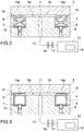
- Figure 2 shows the gaskets 14 and 15 in their resting configuration, in which they are housed in their respective seats 6 and 7, all substantially below the plane defined by the annular portion 8
- Figure 3 shows the seals 14 and 15 in their working configuration, in which their respective front portions 14a and 15a project from the seats 6 and 7 and create a seal on the inner surface of the closing panel 5.
- the interposition of the gaskets 14 and 15 between the closing panel 5 and the annular portion 8 defines a hollow space 18 ( Figures 2 and 3 ) between the inner surface of the closing panel 5, the annular portion 8, and in particular the sub-portion 8a, and the gaskets 14 and 15.
- the hollow space 18 is in all respects a small chamber separating the chamber 2 from the environment 1 to eliminate or at least to reduce as much as possible the fluid exchange (air and liquid) between the chamber 2 and the environment 1 when the closing panel 5 is closed.
- the annular portion 8 has a hole 11 at the hollow space 18, i.e. the hole 11 is drilled in the sub-portion 8a, and the sealing system comprises a control chamber 12 ( Figure 1 ) and a conduit 13 to connect the hole 11 to the control chamber 12 so as to connect the hollow space 18 to the control chamber 12.
- the hole 11 is a through hole, i.e. it passes through the wall 4 of the chamber 2, and has an outer end facing the hollow space 18 and an inner end connected to the conduit 13.
- the sealing system also comprises one or more valves, for example two valves, to have a minimum of safety redundancy, indicated with 16 and 17 in the figures, arranged in several points of the conduit 13 to allow or block the fluid circulation in the conduit 13.
- the sealing system also comprises a sucking pump 19 arranged in the control chamber 12 to create a given vacuum in the hollow space 18, so as to suck toxic and/or radioactive fluids that might possibly leak, in use, from the gasket 14, namely from the gasket which is closest to the opening 3, and so as to collect them in the control chamber 12. In this way any small leak of the gaskets 14 and 15 is automatically corrected.
- the control chamber 12 then becomes a tank of toxic and/or radioactive fluids.
- the system finally comprises fluid analysis means (not shown) connected to the control chamber 12 to detect the presence of toxic substances in the hollow space 18, for example so-called “particle counting instruments", mass spectrometers or oxygen concentration sensors, and/or to measure physical parameters of the fluids contained in the hollow space 18, for example to measure pressure, temperature and relative humidity of the fluids.
- fluid analysis means (not shown) connected to the control chamber 12 to detect the presence of toxic substances in the hollow space 18, for example so-called “particle counting instruments", mass spectrometers or oxygen concentration sensors, and/or to measure physical parameters of the fluids contained in the hollow space 18, for example to measure pressure, temperature and relative humidity of the fluids.
- the aforesaid observations or measurements can be carried out as described in ISO 10648.
- a method for checking the hermetic seal of the aforesaid sealing system 1 comprising creating and maintaining a given vacuum or a given overpressure in said hollow space 18 by means of a sucking pump 19 or of a compressor arranged in said control chamber 12 and connected to the conduit 13 and measuring the pressure changes in the hollow space 18 during a predetermined amount of time.
- a sucking pump 19 or of a compressor arranged in said control chamber 12 and connected to the conduit 13 and measuring the pressure changes in the hollow space 18 during a predetermined amount of time.
Landscapes
- Physics & Mathematics (AREA)
- Engineering & Computer Science (AREA)
- General Engineering & Computer Science (AREA)
- High Energy & Nuclear Physics (AREA)
- Gasket Seals (AREA)
- Sealing Using Fluids, Sealing Without Contact, And Removal Of Oil (AREA)
- Measurement Of Radiation (AREA)
Description
- The present invention concerns a system to hermetically seal an access opening to a chamber suited to contain toxic and/or radioactive fluids.
- In particular, the present invention finds an advantageous, but not exclusive, application in ports or mobile doors for closing an access opening to a bunker containing a cyclotron for the production of radiopharmaceuticals, to which the following description will make explicit reference without thereby losing its generality.
- A bunker containing a cyclotron must have a high degree of confinement and tightness to prevent the highly radioactive and toxic gases produced during the cyclotron operation from coming out of the bunker and contaminating the outside environment. The most critical area subject to this confinement is the sealing system of the mobile door closing the access opening to the bunker.
- Existing regulations state that the level of confinement and tightness of the bunker must be measurable. If the bunker has a small size and all its walls guarantee its tightness, it is possible to perform measurements that qualify environmental insulation by means of known measuring systems. If, however, the bunker has some panel that does not ensures tightness or has a size and environmental parameters (such as pressure and temperature) which are not constant, normal measuring systems are not effective, and current regulations require to perform detection tests on detectable fluids by means of special instruments, e.g. an electronic gas sniffer, or instruments which can detect coloured liquids. Tests with detectable fluids have high costs and are sometimes incompatible because they are a source of possible environmental contamination.
- The object of the present invention is to provide a system to hermetically seal an access opening to a bunker, said system allowing to simplify the qualification procedure of environmental insulation of the bunker and, at the same time, being of easy and economic realization.
- According to the present invention it is provided a system to hermetically seal an access opening to a chamber suited to contain toxic and/or radioactive fluids, as defined in the appended claims.
- Korean patent
KR 100760597 B1 - Japanese patent application
JP 07-142418 A - The present invention will now be described with reference to the accompanying drawings, which illustrate a non-limitative embodiment, wherein:
-
Figure 1 shows, in a perspective view, the sealing system according to the present invention; and -
Figures 2 and 3 show, in respective cross-sectional views along the same horizontal plane, a portion of the sealing system ofFigure 1 wherein two sealing gaskets are visible in two different embodiments. - In
Figure 1 , the reference 1 generally indicates an environment whose atmosphere is not harmful to human health, and 2 indicates the inner chamber of a bunker for a cyclotron, i.e. an environment containing, in use, a dangerous atmosphere to human health due to the presence of radioactive and/or toxic substances. Thechamber 2 is defined bywalls 4 able to retain radioactive and toxic substances and has arectangular opening 3 to allow the access of the operator or the passage of objects when the cyclotron is turned off, and therefore when thechamber 2 does not contain any radioactive and/or toxic substances. - With reference to
Figure 1 , the sealing system according to the present invention comprises a mobile closing panel, which is formed, for example, by aclosing panel 5, sliding parallel to the plane of theopening 3 to be arranged in front of anannular portion 8 of thewall 4 surrounding theopening 3 so as to close theopening 3, and by at least twoannular gaskets 15 and 16 (Figure 2 ), suited to be interposed, concentrically to one another and mutually spaced, between theclosing panel 5 and theannular portion 8 to ensure the hermetic sealing. In particular, theannular portion 8 comprises at least two mutually concentricannular seats annular sub-portion 8a of theannular portion 8, each of thegaskets seats Figure 1 , theseats seals seats seals opening 3. - With reference to
Figures 2 and 3 , showing a portion of theclosing panel 5 in front of theannular portion 8, thegaskets fluid supply ducts Figure 2 shows thegaskets respective seats annular portion 8, andFigure 3 shows theseals front portions seats closing panel 5. - With reference to
Figures 1 ,2 and 3 , the interposition of thegaskets closing panel 5 and theannular portion 8 defines a hollow space 18 (Figures 2 and 3 ) between the inner surface of theclosing panel 5, theannular portion 8, and in particular thesub-portion 8a, and thegaskets hollow space 18 is in all respects a small chamber separating thechamber 2 from the environment 1 to eliminate or at least to reduce as much as possible the fluid exchange (air and liquid) between thechamber 2 and the environment 1 when theclosing panel 5 is closed. - According to the invention, the
annular portion 8 has ahole 11 at thehollow space 18, i.e. thehole 11 is drilled in thesub-portion 8a, and the sealing system comprises a control chamber 12 (Figure 1 ) and aconduit 13 to connect thehole 11 to thecontrol chamber 12 so as to connect thehollow space 18 to thecontrol chamber 12. In particular, thehole 11 is a through hole, i.e. it passes through thewall 4 of thechamber 2, and has an outer end facing thehollow space 18 and an inner end connected to theconduit 13. - The sealing system also comprises one or more valves, for example two valves, to have a minimum of safety redundancy, indicated with 16 and 17 in the figures, arranged in several points of the
conduit 13 to allow or block the fluid circulation in theconduit 13. - The sealing system also comprises a sucking
pump 19 arranged in thecontrol chamber 12 to create a given vacuum in thehollow space 18, so as to suck toxic and/or radioactive fluids that might possibly leak, in use, from thegasket 14, namely from the gasket which is closest to theopening 3, and so as to collect them in thecontrol chamber 12. In this way any small leak of thegaskets control chamber 12 then becomes a tank of toxic and/or radioactive fluids. - The system finally comprises fluid analysis means (not shown) connected to the
control chamber 12 to detect the presence of toxic substances in thehollow space 18, for example so-called "particle counting instruments", mass spectrometers or oxygen concentration sensors, and/or to measure physical parameters of the fluids contained in thehollow space 18, for example to measure pressure, temperature and relative humidity of the fluids. The aforesaid observations or measurements can be carried out as described in ISO 10648. - According to a further aspect of the invention, it is provided a method for checking the hermetic seal of the aforesaid sealing system 1, the method comprising creating and maintaining a given vacuum or a given overpressure in said
hollow space 18 by means of a suckingpump 19 or of a compressor arranged in saidcontrol chamber 12 and connected to theconduit 13 and measuring the pressure changes in thehollow space 18 during a predetermined amount of time. In this way the hermetic seal of the sealing system can be checked regardless of the porosity and the degree of confinement guaranteed by thewalls 4. - Although the aforesaid description makes particular reference to a very specific embodiment, the present invention is not to be considered limited to said embodiment, falling within its scope all those variations, modifications or simplifications covered by the appended claims, such as for example:
- closing panel formed by a hinged door or window that abuts on the
annular portion 8 or on other parts of thewall 4; - a number of concentric gaskets greater than two, anyway determined according to the required degree of sealing, and a number of gasket-separating annular sub-portions, and therefore a number of
holes 11, equal to the number of gaskets minus one; and -
chamber 2 is a containment chamber for a nuclear, pharmaceutical or radiopharmaceutical use.
Claims (7)
- A system to hermetically seal an access opening allowing access to a chamber suited to contain toxic and/or radioactive fluids, the system comprising a mobile closing panel (5) to be arranged, in use, in front of an annular wall portion (8) of the chamber (2) surrounding said opening (3), so as to close the opening (3) itself, and at least two sealing gaskets (14, 15), which have an annular shape and are suited to be interposed, concentrically to one another, between the closing panel (5) and the annular portion (8), so as to ensure a hermetic seal and to define a hollow space (18) between the inner surface of the closing panel (5), the annular portion (8) and the two gaskets (14, 15); the annular portion (8) having a hole (11) in correspondence to said hollow space (18); the system comprising a control chamber (12) and a conduit (13) to connect the hole (11) to the control chamber (12), so as to establish a communication between the hollow space (18) and the control chamber (12), thus allowing the hermetic seal of the system to be controlled, and being characterised in that said gaskets consist of dynamic expansion gaskets (14, 15) which are suited to be expanded when said closing panel (5) is in front of said annular portion (8).
- A system according to claim 1 and comprising at least two annular seats (6, 7), which are arranged along said annular portion (8) and are mutually separated by an annular sub-portion (8a) of the annular portion (8), and said gaskets (14, 15) are each arranged in a respective one of the two seats (6, 7), so that said hollow space (18) is defined between the inner surface of the closing panel (5) and said annular sub-portion (8a); said hole (11) being obtained in said annular sub-portion (8a).
- A system according to claim 2, wherein said gaskets (14, 15) have respective front portions (14a, 15a) which project from the plane defined by said annular portion (8) at least when the closing panel (5) is in front of said annular portion (8) so as to create a seal with said inner surface of the closing panel (5) in order to define said hollow space (18).
- A system according to any of the claims from 1 to 3 and comprising at least one valve (16, 17) which is mounted in a respective point of said conduit (13) so as to permit or hinder the circulation of fluids in the conduit (13).
- A system according to any of the claims from 1 to 4 and comprising fluid analysis means which are connected to said control chamber (12) so as to detect the presence of toxic substances in said hollow space (18) and/or to measure physical parameters of the fluids contained in the hollow space (18).
- A system according to any of the claims from 1 to 5 and comprising a sucking pump (19) arranged in said control chamber (12) to create a given vacuum in said hollow space (18), so as to suck toxic and/or radioactive fluids that might possibly leak, in use, from the gasket (14) that is closest to said opening (3) and so as to collect them in the control chamber (12).
- A method to control the hermetic seal of a sealing system according to any of the claims from 1 to 6, the method comprising:- creating and maintaining a given vacuum or a given overpressure in said hollow space (18) by means of a sucking pump (19) or of a compressor arranged in said control chamber (12); and- measuring the pressure changes in the hollow space (18) during a predetermined amount of time.
Applications Claiming Priority (1)
| Application Number | Priority Date | Filing Date | Title |
|---|---|---|---|
| ITBO20140103 | 2014-03-03 |
Publications (2)
| Publication Number | Publication Date |
|---|---|
| EP2916326A1 EP2916326A1 (en) | 2015-09-09 |
| EP2916326B1 true EP2916326B1 (en) | 2017-09-20 |
Family
ID=50349701
Family Applications (1)
| Application Number | Title | Priority Date | Filing Date |
|---|---|---|---|
| EP15157481.1A Active EP2916326B1 (en) | 2014-03-03 | 2015-03-03 | A system to hermetically seal an access opening allowing access to a chamber suited to contain toxic and/or radioactive fluids |
Country Status (3)
| Country | Link |
|---|---|
| EP (1) | EP2916326B1 (en) |
| DK (1) | DK2916326T3 (en) |
| ES (1) | ES2649181T3 (en) |
Cited By (1)
| Publication number | Priority date | Publication date | Assignee | Title |
|---|---|---|---|---|
| US11851221B2 (en) | 2022-04-21 | 2023-12-26 | Curium Us Llc | Systems and methods for producing a radioactive drug product using a dispensing unit |
Family Cites Families (2)
| Publication number | Priority date | Publication date | Assignee | Title |
|---|---|---|---|---|
| JP3449636B2 (en) * | 1993-11-12 | 2003-09-22 | 株式会社日立国際電気 | Semiconductor manufacturing equipment |
| JP2001298076A (en) * | 2000-04-12 | 2001-10-26 | Sony Corp | Substrate transport container |
-
2015
- 2015-03-03 ES ES15157481.1T patent/ES2649181T3/en active Active
- 2015-03-03 EP EP15157481.1A patent/EP2916326B1/en active Active
- 2015-03-03 DK DK15157481.1T patent/DK2916326T3/en active
Non-Patent Citations (1)
| Title |
|---|
| None * |
Cited By (2)
| Publication number | Priority date | Publication date | Assignee | Title |
|---|---|---|---|---|
| US11851221B2 (en) | 2022-04-21 | 2023-12-26 | Curium Us Llc | Systems and methods for producing a radioactive drug product using a dispensing unit |
| US12428177B2 (en) | 2022-04-21 | 2025-09-30 | Curium Us Llc | Systems and methods for producing a radioactive drug product using a dispensing unit |
Also Published As
| Publication number | Publication date |
|---|---|
| EP2916326A1 (en) | 2015-09-09 |
| DK2916326T3 (en) | 2018-01-02 |
| ES2649181T3 (en) | 2018-01-10 |
Similar Documents
| Publication | Publication Date | Title |
|---|---|---|
| RU2699927C2 (en) | Film chamber with measuring volume for large leak detection | |
| JP6742424B2 (en) | On-line sealed detection device, multi-compartment sealed chamber type processing equipment and method | |
| US20100314975A1 (en) | Glovebox for a double wall containment module | |
| EP4070063B1 (en) | Sealing arrangement, filter and filter housing, method of monitoring leak tightness, and leak tightness monitoring system | |
| KR20150012201A (en) | External seal structure of vacuum valve | |
| JP2017526935A5 (en) | ||
| DK2916326T3 (en) | System for hermetically sealing an access opening which provides access to a chamber suitable for containing toxic and / or radioactive liquids | |
| KR920003332A (en) | Gas pressure monitoring devices in casks containing latent disturbance gases and methods of determining the cause of leaks detected by such devices | |
| JPWO2020246592A5 (en) | ||
| CN105841790A (en) | Weighing method equipment with blocking structure and weighing method thereof | |
| KR102287932B9 (en) | Seal with gas leak detection function high pressure gas container and gas leak monitoring system equipped with the same | |
| WO2022131989A1 (en) | Sealing device | |
| JP2015534088A (en) | Leak detector | |
| JP6817164B2 (en) | Storage container for radioactive materials | |
| US11617811B2 (en) | Sterile container comprising a vapour-permeable seal | |
| JPH0155440B2 (en) | ||
| CN111060262A (en) | Sealing performance detection device and battery sealing performance detection method | |
| KR102858239B1 (en) | Ammonia ISO tank integrated control method and system for this | |
| US20050160797A1 (en) | Field device for determining and/or monitoring a process variable | |
| KR101540172B1 (en) | Device for detecting the gas leakage | |
| KR20170068175A (en) | Device for detecting gas | |
| TW202128280A (en) | Seal-testing device for a double-door transfer system | |
| RU2697656C1 (en) | Method for long-term dry storage of spent nuclear fuel and container for its implementation | |
| US20260016359A1 (en) | Emission monitoring | |
| JPH04187897A (en) | Backup system in case of abnormality of dry-gas seal |
Legal Events
| Date | Code | Title | Description |
|---|---|---|---|
| PUAI | Public reference made under article 153(3) epc to a published international application that has entered the european phase |
Free format text: ORIGINAL CODE: 0009012 |
|
| AK | Designated contracting states |
Kind code of ref document: A1 Designated state(s): AL AT BE BG CH CY CZ DE DK EE ES FI FR GB GR HR HU IE IS IT LI LT LU LV MC MK MT NL NO PL PT RO RS SE SI SK SM TR |
|
| AX | Request for extension of the european patent |
Extension state: BA ME |
|
| 17P | Request for examination filed |
Effective date: 20160308 |
|
| RBV | Designated contracting states (corrected) |
Designated state(s): AL AT BE BG CH CY CZ DE DK EE ES FI FR GB GR HR HU IE IS IT LI LT LU LV MC MK MT NL NO PL PT RO RS SE SI SK SM TR |
|
| GRAP | Despatch of communication of intention to grant a patent |
Free format text: ORIGINAL CODE: EPIDOSNIGR1 |
|
| INTG | Intention to grant announced |
Effective date: 20170406 |
|
| GRAS | Grant fee paid |
Free format text: ORIGINAL CODE: EPIDOSNIGR3 |
|
| GRAA | (expected) grant |
Free format text: ORIGINAL CODE: 0009210 |
|
| AK | Designated contracting states |
Kind code of ref document: B1 Designated state(s): AL AT BE BG CH CY CZ DE DK EE ES FI FR GB GR HR HU IE IS IT LI LT LU LV MC MK MT NL NO PL PT RO RS SE SI SK SM TR |
|
| REG | Reference to a national code |
Ref country code: GB Ref legal event code: FG4D |
|
| REG | Reference to a national code |
Ref country code: CH Ref legal event code: EP |
|
| REG | Reference to a national code |
Ref country code: AT Ref legal event code: REF Ref document number: 930752 Country of ref document: AT Kind code of ref document: T Effective date: 20171015 |
|
| REG | Reference to a national code |
Ref country code: IE Ref legal event code: FG4D |
|
| REG | Reference to a national code |
Ref country code: DE Ref legal event code: R096 Ref document number: 602015004823 Country of ref document: DE |
|
| REG | Reference to a national code |
Ref country code: NL Ref legal event code: FP |
|
| REG | Reference to a national code |
Ref country code: DK Ref legal event code: T3 Effective date: 20171220 |
|
| REG | Reference to a national code |
Ref country code: ES Ref legal event code: FG2A Ref document number: 2649181 Country of ref document: ES Kind code of ref document: T3 Effective date: 20180110 |
|
| PG25 | Lapsed in a contracting state [announced via postgrant information from national office to epo] |
Ref country code: FI Free format text: LAPSE BECAUSE OF FAILURE TO SUBMIT A TRANSLATION OF THE DESCRIPTION OR TO PAY THE FEE WITHIN THE PRESCRIBED TIME-LIMIT Effective date: 20170920 Ref country code: SE Free format text: LAPSE BECAUSE OF FAILURE TO SUBMIT A TRANSLATION OF THE DESCRIPTION OR TO PAY THE FEE WITHIN THE PRESCRIBED TIME-LIMIT Effective date: 20170920 Ref country code: LT Free format text: LAPSE BECAUSE OF FAILURE TO SUBMIT A TRANSLATION OF THE DESCRIPTION OR TO PAY THE FEE WITHIN THE PRESCRIBED TIME-LIMIT Effective date: 20170920 Ref country code: HR Free format text: LAPSE BECAUSE OF FAILURE TO SUBMIT A TRANSLATION OF THE DESCRIPTION OR TO PAY THE FEE WITHIN THE PRESCRIBED TIME-LIMIT Effective date: 20170920 Ref country code: NO Free format text: LAPSE BECAUSE OF FAILURE TO SUBMIT A TRANSLATION OF THE DESCRIPTION OR TO PAY THE FEE WITHIN THE PRESCRIBED TIME-LIMIT Effective date: 20171220 |
|
| REG | Reference to a national code |
Ref country code: LT Ref legal event code: MG4D |
|
| PG25 | Lapsed in a contracting state [announced via postgrant information from national office to epo] |
Ref country code: RS Free format text: LAPSE BECAUSE OF FAILURE TO SUBMIT A TRANSLATION OF THE DESCRIPTION OR TO PAY THE FEE WITHIN THE PRESCRIBED TIME-LIMIT Effective date: 20170920 Ref country code: BG Free format text: LAPSE BECAUSE OF FAILURE TO SUBMIT A TRANSLATION OF THE DESCRIPTION OR TO PAY THE FEE WITHIN THE PRESCRIBED TIME-LIMIT Effective date: 20171220 Ref country code: GR Free format text: LAPSE BECAUSE OF FAILURE TO SUBMIT A TRANSLATION OF THE DESCRIPTION OR TO PAY THE FEE WITHIN THE PRESCRIBED TIME-LIMIT Effective date: 20171221 Ref country code: LV Free format text: LAPSE BECAUSE OF FAILURE TO SUBMIT A TRANSLATION OF THE DESCRIPTION OR TO PAY THE FEE WITHIN THE PRESCRIBED TIME-LIMIT Effective date: 20170920 |
|
| REG | Reference to a national code |
Ref country code: FR Ref legal event code: PLFP Year of fee payment: 4 |
|
| PG25 | Lapsed in a contracting state [announced via postgrant information from national office to epo] |
Ref country code: PL Free format text: LAPSE BECAUSE OF FAILURE TO SUBMIT A TRANSLATION OF THE DESCRIPTION OR TO PAY THE FEE WITHIN THE PRESCRIBED TIME-LIMIT Effective date: 20170920 Ref country code: RO Free format text: LAPSE BECAUSE OF FAILURE TO SUBMIT A TRANSLATION OF THE DESCRIPTION OR TO PAY THE FEE WITHIN THE PRESCRIBED TIME-LIMIT Effective date: 20170920 Ref country code: CZ Free format text: LAPSE BECAUSE OF FAILURE TO SUBMIT A TRANSLATION OF THE DESCRIPTION OR TO PAY THE FEE WITHIN THE PRESCRIBED TIME-LIMIT Effective date: 20170920 |
|
| PG25 | Lapsed in a contracting state [announced via postgrant information from national office to epo] |
Ref country code: EE Free format text: LAPSE BECAUSE OF FAILURE TO SUBMIT A TRANSLATION OF THE DESCRIPTION OR TO PAY THE FEE WITHIN THE PRESCRIBED TIME-LIMIT Effective date: 20170920 Ref country code: SK Free format text: LAPSE BECAUSE OF FAILURE TO SUBMIT A TRANSLATION OF THE DESCRIPTION OR TO PAY THE FEE WITHIN THE PRESCRIBED TIME-LIMIT Effective date: 20170920 Ref country code: SM Free format text: LAPSE BECAUSE OF FAILURE TO SUBMIT A TRANSLATION OF THE DESCRIPTION OR TO PAY THE FEE WITHIN THE PRESCRIBED TIME-LIMIT Effective date: 20170920 Ref country code: IS Free format text: LAPSE BECAUSE OF FAILURE TO SUBMIT A TRANSLATION OF THE DESCRIPTION OR TO PAY THE FEE WITHIN THE PRESCRIBED TIME-LIMIT Effective date: 20180120 |
|
| REG | Reference to a national code |
Ref country code: DE Ref legal event code: R097 Ref document number: 602015004823 Country of ref document: DE |
|
| PLBE | No opposition filed within time limit |
Free format text: ORIGINAL CODE: 0009261 |
|
| STAA | Information on the status of an ep patent application or granted ep patent |
Free format text: STATUS: NO OPPOSITION FILED WITHIN TIME LIMIT |
|
| 26N | No opposition filed |
Effective date: 20180621 |
|
| REG | Reference to a national code |
Ref country code: CH Ref legal event code: PL |
|
| PG25 | Lapsed in a contracting state [announced via postgrant information from national office to epo] |
Ref country code: MC Free format text: LAPSE BECAUSE OF FAILURE TO SUBMIT A TRANSLATION OF THE DESCRIPTION OR TO PAY THE FEE WITHIN THE PRESCRIBED TIME-LIMIT Effective date: 20170920 Ref country code: SI Free format text: LAPSE BECAUSE OF FAILURE TO SUBMIT A TRANSLATION OF THE DESCRIPTION OR TO PAY THE FEE WITHIN THE PRESCRIBED TIME-LIMIT Effective date: 20170920 |
|
| REG | Reference to a national code |
Ref country code: IE Ref legal event code: MM4A |
|
| PG25 | Lapsed in a contracting state [announced via postgrant information from national office to epo] |
Ref country code: LU Free format text: LAPSE BECAUSE OF NON-PAYMENT OF DUE FEES Effective date: 20180303 |
|
| PG25 | Lapsed in a contracting state [announced via postgrant information from national office to epo] |
Ref country code: IE Free format text: LAPSE BECAUSE OF NON-PAYMENT OF DUE FEES Effective date: 20180303 |
|
| PG25 | Lapsed in a contracting state [announced via postgrant information from national office to epo] |
Ref country code: LI Free format text: LAPSE BECAUSE OF NON-PAYMENT OF DUE FEES Effective date: 20180331 Ref country code: CH Free format text: LAPSE BECAUSE OF NON-PAYMENT OF DUE FEES Effective date: 20180331 |
|
| REG | Reference to a national code |
Ref country code: AT Ref legal event code: UEP Ref document number: 930752 Country of ref document: AT Kind code of ref document: T Effective date: 20170920 |
|
| PG25 | Lapsed in a contracting state [announced via postgrant information from national office to epo] |
Ref country code: MT Free format text: LAPSE BECAUSE OF NON-PAYMENT OF DUE FEES Effective date: 20180303 |
|
| PG25 | Lapsed in a contracting state [announced via postgrant information from national office to epo] |
Ref country code: TR Free format text: LAPSE BECAUSE OF FAILURE TO SUBMIT A TRANSLATION OF THE DESCRIPTION OR TO PAY THE FEE WITHIN THE PRESCRIBED TIME-LIMIT Effective date: 20170920 |
|
| PG25 | Lapsed in a contracting state [announced via postgrant information from national office to epo] |
Ref country code: PT Free format text: LAPSE BECAUSE OF FAILURE TO SUBMIT A TRANSLATION OF THE DESCRIPTION OR TO PAY THE FEE WITHIN THE PRESCRIBED TIME-LIMIT Effective date: 20170920 |
|
| PG25 | Lapsed in a contracting state [announced via postgrant information from national office to epo] |
Ref country code: CY Free format text: LAPSE BECAUSE OF FAILURE TO SUBMIT A TRANSLATION OF THE DESCRIPTION OR TO PAY THE FEE WITHIN THE PRESCRIBED TIME-LIMIT Effective date: 20170920 Ref country code: HU Free format text: LAPSE BECAUSE OF FAILURE TO SUBMIT A TRANSLATION OF THE DESCRIPTION OR TO PAY THE FEE WITHIN THE PRESCRIBED TIME-LIMIT; INVALID AB INITIO Effective date: 20150303 Ref country code: MK Free format text: LAPSE BECAUSE OF NON-PAYMENT OF DUE FEES Effective date: 20170920 |
|
| PG25 | Lapsed in a contracting state [announced via postgrant information from national office to epo] |
Ref country code: AL Free format text: LAPSE BECAUSE OF FAILURE TO SUBMIT A TRANSLATION OF THE DESCRIPTION OR TO PAY THE FEE WITHIN THE PRESCRIBED TIME-LIMIT Effective date: 20170920 |
|
| P01 | Opt-out of the competence of the unified patent court (upc) registered |
Effective date: 20230912 |
|
| PGFP | Annual fee paid to national office [announced via postgrant information from national office to epo] |
Ref country code: ES Payment date: 20250423 Year of fee payment: 11 |
|
| PGFP | Annual fee paid to national office [announced via postgrant information from national office to epo] |
Ref country code: GB Payment date: 20260304 Year of fee payment: 12 |
|
| PGFP | Annual fee paid to national office [announced via postgrant information from national office to epo] |
Ref country code: DE Payment date: 20260320 Year of fee payment: 12 Ref country code: DK Payment date: 20260323 Year of fee payment: 12 |
|
| PGFP | Annual fee paid to national office [announced via postgrant information from national office to epo] |
Ref country code: AT Payment date: 20260318 Year of fee payment: 12 |
|
| PGFP | Annual fee paid to national office [announced via postgrant information from national office to epo] |
Ref country code: BE Payment date: 20260323 Year of fee payment: 12 Ref country code: IT Payment date: 20260302 Year of fee payment: 12 |
|
| PGFP | Annual fee paid to national office [announced via postgrant information from national office to epo] |
Ref country code: NL Payment date: 20260323 Year of fee payment: 12 |
|
| PGFP | Annual fee paid to national office [announced via postgrant information from national office to epo] |
Ref country code: FR Payment date: 20260323 Year of fee payment: 12 |