EP2916104B1 - Dispositif de réflecteur avec rétroréflecteur et avec dispositif de capteurs pour la détermination d'inclinaison et l'étalonnage - Google Patents
Dispositif de réflecteur avec rétroréflecteur et avec dispositif de capteurs pour la détermination d'inclinaison et l'étalonnage Download PDFInfo
- Publication number
- EP2916104B1 EP2916104B1 EP14158265.0A EP14158265A EP2916104B1 EP 2916104 B1 EP2916104 B1 EP 2916104B1 EP 14158265 A EP14158265 A EP 14158265A EP 2916104 B1 EP2916104 B1 EP 2916104B1
- Authority
- EP
- European Patent Office
- Prior art keywords
- sensor
- arrangement
- inclination
- reflector
- respect
- Prior art date
- Legal status (The legal status is an assumption and is not a legal conclusion. Google has not performed a legal analysis and makes no representation as to the accuracy of the status listed.)
- Active
Links
- 230000005855 radiation Effects 0.000 claims description 97
- 238000005286 illumination Methods 0.000 claims description 74
- 238000005259 measurement Methods 0.000 claims description 39
- 238000001514 detection method Methods 0.000 claims description 36
- 230000003287 optical effect Effects 0.000 claims description 21
- 230000005540 biological transmission Effects 0.000 claims description 14
- 238000000034 method Methods 0.000 claims description 14
- 238000012545 processing Methods 0.000 claims description 13
- 230000001419 dependent effect Effects 0.000 claims description 10
- 230000008685 targeting Effects 0.000 claims description 7
- 230000008859 change Effects 0.000 claims description 5
- 238000004590 computer program Methods 0.000 claims description 5
- 230000005670 electromagnetic radiation Effects 0.000 claims description 4
- 230000001678 irradiating effect Effects 0.000 claims description 2
- 230000002123 temporal effect Effects 0.000 claims 2
- 241000219739 Lens Species 0.000 description 31
- 238000013461 design Methods 0.000 description 9
- 230000006870 function Effects 0.000 description 6
- 239000000758 substrate Substances 0.000 description 6
- 230000000712 assembly Effects 0.000 description 5
- 238000000429 assembly Methods 0.000 description 5
- 239000011521 glass Substances 0.000 description 4
- 239000011159 matrix material Substances 0.000 description 4
- 230000007704 transition Effects 0.000 description 4
- 230000001133 acceleration Effects 0.000 description 3
- 238000011896 sensitive detection Methods 0.000 description 3
- 238000012935 Averaging Methods 0.000 description 2
- 238000010276 construction Methods 0.000 description 2
- 238000006073 displacement reaction Methods 0.000 description 2
- 238000011156 evaluation Methods 0.000 description 2
- 230000005484 gravity Effects 0.000 description 2
- 238000003384 imaging method Methods 0.000 description 2
- 230000003993 interaction Effects 0.000 description 2
- 230000004807 localization Effects 0.000 description 2
- 230000002093 peripheral effect Effects 0.000 description 2
- 229920003023 plastic Polymers 0.000 description 2
- 230000008569 process Effects 0.000 description 2
- 238000012546 transfer Methods 0.000 description 2
- 240000004322 Lens culinaris Species 0.000 description 1
- 241001422033 Thestylus Species 0.000 description 1
- 238000004458 analytical method Methods 0.000 description 1
- 238000013459 approach Methods 0.000 description 1
- 238000003491 array Methods 0.000 description 1
- 238000004364 calculation method Methods 0.000 description 1
- 239000003795 chemical substances by application Substances 0.000 description 1
- 230000001427 coherent effect Effects 0.000 description 1
- 238000004891 communication Methods 0.000 description 1
- 238000012790 confirmation Methods 0.000 description 1
- 238000013500 data storage Methods 0.000 description 1
- 230000003247 decreasing effect Effects 0.000 description 1
- 238000000605 extraction Methods 0.000 description 1
- 230000010354 integration Effects 0.000 description 1
- LFEUVBZXUFMACD-UHFFFAOYSA-H lead(2+);trioxido(oxo)-$l^{5}-arsane Chemical compound [Pb+2].[Pb+2].[Pb+2].[O-][As]([O-])([O-])=O.[O-][As]([O-])([O-])=O LFEUVBZXUFMACD-UHFFFAOYSA-H 0.000 description 1
- 230000000670 limiting effect Effects 0.000 description 1
- 239000007788 liquid Substances 0.000 description 1
- 238000013507 mapping Methods 0.000 description 1
- 230000000873 masking effect Effects 0.000 description 1
- 230000036961 partial effect Effects 0.000 description 1
- 230000003954 pattern orientation Effects 0.000 description 1
- 230000000737 periodic effect Effects 0.000 description 1
- 230000002829 reductive effect Effects 0.000 description 1
- 230000035945 sensitivity Effects 0.000 description 1
- 238000007493 shaping process Methods 0.000 description 1
- 230000008054 signal transmission Effects 0.000 description 1
- 230000004304 visual acuity Effects 0.000 description 1
Images


Classifications
-
- G—PHYSICS
- G01—MEASURING; TESTING
- G01C—MEASURING DISTANCES, LEVELS OR BEARINGS; SURVEYING; NAVIGATION; GYROSCOPIC INSTRUMENTS; PHOTOGRAMMETRY OR VIDEOGRAMMETRY
- G01C15/00—Surveying instruments or accessories not provided for in groups G01C1/00 - G01C13/00
- G01C15/002—Active optical surveying means
- G01C15/008—Active optical surveying means combined with inclination sensor
-
- G—PHYSICS
- G01—MEASURING; TESTING
- G01C—MEASURING DISTANCES, LEVELS OR BEARINGS; SURVEYING; NAVIGATION; GYROSCOPIC INSTRUMENTS; PHOTOGRAMMETRY OR VIDEOGRAMMETRY
- G01C15/00—Surveying instruments or accessories not provided for in groups G01C1/00 - G01C13/00
- G01C15/002—Active optical surveying means
- G01C15/004—Reference lines, planes or sectors
- G01C15/006—Detectors therefor
-
- G—PHYSICS
- G01—MEASURING; TESTING
- G01C—MEASURING DISTANCES, LEVELS OR BEARINGS; SURVEYING; NAVIGATION; GYROSCOPIC INSTRUMENTS; PHOTOGRAMMETRY OR VIDEOGRAMMETRY
- G01C15/00—Surveying instruments or accessories not provided for in groups G01C1/00 - G01C13/00
- G01C15/02—Means for marking measuring points
- G01C15/06—Surveyors' staffs; Movable markers
-
- G—PHYSICS
- G01—MEASURING; TESTING
- G01C—MEASURING DISTANCES, LEVELS OR BEARINGS; SURVEYING; NAVIGATION; GYROSCOPIC INSTRUMENTS; PHOTOGRAMMETRY OR VIDEOGRAMMETRY
- G01C25/00—Manufacturing, calibrating, cleaning, or repairing instruments or devices referred to in the other groups of this subclass
-
- G—PHYSICS
- G01—MEASURING; TESTING
- G01S—RADIO DIRECTION-FINDING; RADIO NAVIGATION; DETERMINING DISTANCE OR VELOCITY BY USE OF RADIO WAVES; LOCATING OR PRESENCE-DETECTING BY USE OF THE REFLECTION OR RERADIATION OF RADIO WAVES; ANALOGOUS ARRANGEMENTS USING OTHER WAVES
- G01S17/00—Systems using the reflection or reradiation of electromagnetic waves other than radio waves, e.g. lidar systems
- G01S17/86—Combinations of lidar systems with systems other than lidar, radar or sonar, e.g. with direction finders
-
- G—PHYSICS
- G01—MEASURING; TESTING
- G01S—RADIO DIRECTION-FINDING; RADIO NAVIGATION; DETERMINING DISTANCE OR VELOCITY BY USE OF RADIO WAVES; LOCATING OR PRESENCE-DETECTING BY USE OF THE REFLECTION OR RERADIATION OF RADIO WAVES; ANALOGOUS ARRANGEMENTS USING OTHER WAVES
- G01S7/00—Details of systems according to groups G01S13/00, G01S15/00, G01S17/00
- G01S7/48—Details of systems according to groups G01S13/00, G01S15/00, G01S17/00 of systems according to group G01S17/00
- G01S7/481—Constructional features, e.g. arrangements of optical elements
- G01S7/4811—Constructional features, e.g. arrangements of optical elements common to transmitter and receiver
Definitions
- the invention relates to a reflector arrangement for determining the position and / or marking of target points, in particular for structural or geodetic surveying, according to the preamble of claim 1, a calibration method according to the preamble of claim 11 and a computer program product according to claim 15.
- geodetic surveying equipment include the theodolite, tachymeter, and total station, also referred to as an electronic tachymeter or computer tachymeter.
- a geodetic measuring apparatus of the prior art is disclosed in the publication EP 1 686 350 described.
- Such devices have elektrosensische angle and possibly distance measuring function, which allow a direction and distance determination to a selected destination.
- the angle or distance variables are determined in the inner reference system of the device and may need to be linked to an external reference system for an absolute position determination.
- the display control unit is supplied with the electrosensory measurement data, so that the position of the target point by the display control unit can be determined, visually displayed and stored.
- Total stations known from the prior art can furthermore have a radio data interface for setting up a radio link to external peripheral components, such as a handheld data acquisition device, which can be configured in particular as a data logger or field computer.
- geodetic surveying devices of the generic type comprise a sighting telescope, such as an optical telescope, as a sighting device.
- the scope is generally rotatable about a vertical standing axis and about a horizontal tilting axis relative to a base of the gauge so that the telescope can pivot by pivoting and tilting on measuring point can be aligned.
- Modern devices can additively to the optical view channel integrated into the scope and, for example, coaxial or parallel aligned camera for capturing an image, the captured image especially as a live image on the display of the display control unit and / or on a display for remote control used peripheral device - such as the data logger - can be displayed.
- the optics of the sighting device may have a manual focus - for example, an adjusting screw for changing the position of a focusing optics - or have an autofocus, wherein the changing of the focus position, for example by servomotors.
- a sighting device of a geodetic surveying device in the EP 2 219 011 described.
- Automatic focusing devices for riflescopes of geodetic devices are eg from DE 197 107 22 , of the DE 199 267 06 or the DE 199 495 80 known.
- the construction of generic riflescopes of geodesic devices is in the publications EP 1 081 459 or EP 1 662 278 shown.
- ATR Automatic Target Recognition
- a further separate ATR light source and a special, for this wavelength sensitive ATR detector are additionally integrated in the telescope.
- measuring devices which are specially designed for a continuous tracking of a target point and a coordinate position determination of this point.
- a target point can be represented by a retro-reflective unit (eg cubic prism), which is aimed at with an optical measuring beam of the measuring device, in particular a laser beam.
- the laser beam is reflected back parallel to the measuring device, the reflected beam being detected by a detection unit of the device.
- an emission or reception direction of the beam for example by means of sensors for angle measurement, which are assigned to a deflection mirror or a target unit of the system, determined.
- a distance from the measuring device to the target point for example by means of transit time or phase difference measurement, determined.
- laser trackers of the prior art have at least one distance meter, which may be designed, for example, as an interferometer. Since such distance measuring units can only measure relative distance changes, in today's laser trackers so-called absolute distance meters are installed in addition to interferometers.
- a combination of measuring means for determining the distance is known by the product AT901 from Leica Geosystems AG.
- the interferometers used for the distance measurement in this context mainly use gas lasers as light sources, in particular HeNe gas lasers, due to the great coherence length and the measuring range thus made possible.
- the coherence length of the HeNe laser can be several hundred meters, so that the required in industrial metrology ranges can be achieved with relatively simple interferometer structures.
- a combination of an absolute distance meter and an interferometer for determining distances with a HeNe laser for example, from WO 2007/079600 A1 known.
- points are measured by placing specially designed targets (eg surveying rods) at the target point.
- targets eg surveying rods
- These usually consist of a pole with a reflector (eg an all-round prism) for defining the measuring section or the measuring point.
- Such surveying tasks typically use data to control the measurement process and to establish or register measurement parameters. Transfer instructions, language and other information between the target object - in particular a hand-held data acquisition device on the part of the target object - and the central measuring device. Examples of such data are identification information for the target object (eg type of prism used), inclination of the pole, height of the reflector above ground, reflector constants or measured values such as temperature or air pressure. This information or situation-dependent parameters are required in order to enable a high-precision alignment and measurement of the measuring point defined by the pole with prism.
- target objects or auxiliary measuring instruments are used for measuring a measuring point, in particular a plurality of measuring points.
- targets include non-contact sensors (e.g., mobile optical scanning units) and so-called stylus tools that are positioned with their contact point on the measurement point on an object, thereby allowing a measurement of this target point.
- a determination of the spatial orientation or an inclination with respect to respective relevant spatial directions of the respective auxiliary instrument is required in order to derive the position of the target point to be determined by means of the instrument together with the determined position of the reflector arranged on the auxiliary instrument.
- Such an orientation may be determined, for example, by means of an inclination sensor or an IMU (inertial measurement unit) provided in a specific position and position relative to the reflector or, as typically used for laser trackers, by means of markings arranged on the auxiliary instrument, the positions of the Markings on the stylus are precisely known and the orientation is determined by image processing of an image in which these marks are detected with position reference.
- the image may be captured by an image acquisition unit on the part of an o.g. Surveyor are detected.
- inclination sensors which are typically designed as liquid sensors, or by the IMU, in particular due to the drift of the proposed sensors, given limited accuracy, especially over a longer period of time, for the Inclination or orientation determination.
- the markings provided for determining the orientation contain the additional source of error that, for example, in the case of partial masking of one or more markings, a corresponding orientation determination may possibly still be possible, but the orientation can be determined with only limited accuracy.
- the DE 10 2012 011 518 B3 describes a geodetic target with a matrix sensor whose receiving surface is arranged in an image plane of an imaging optic, which focuses incident measurement beams into a pixel on the matrix sensor.
- the matrix sensor is designed to determine a position of the pixel within the receiving surface, so that based on the position of the pixel within the receiving surface of the matrix sensor possible rotations of the geodetic target about axes can be determined, which lie in a plane which coincides with the optical axis of the Imaging optics include a non-zero angle.
- the invention relates in a first embodiment, a reflector assembly for determining the position and / or marking of target points, in particular for industrial or geodetic surveying, with a Retroreflector for determining the position of the reflector assembly by means of parallel, in particular coaxial, beam reflection and a sensor arrangement, wherein the sensor arrangement comprises a code element with code pattern.
- the sensor arrangement furthermore has a sensor which is sensitive at least with respect to a wavelength range and has a reception direction orthogonal to its detection surface, wherein the code element and the sensor are rigidly connected at a defined distance in such a way that by means of the sensor an angle-dependent position of a projection of the code pattern with respect to the reception direction the detection surface is determinable.
- a distance between the code element and the sensor in this context ie in the context of the present invention, a geometric distance between the two elements - code element and sensor - understood.
- the distance may, for example, be represented by the linear distance from the interface of the code element to the opposite interface of the sensor or by the removal of the respective centers of gravity of the two elements.
- the code element By this arrangement of the code element relative to the sensor also an optical distance is defined, in which case additionally the refractive index n of a located between the code element (or code pattern) and the sensor medium (eg air or glass) is taken into account.
- the optical distance is the geometric distance L (geometric distance) divided by the refractive index n of the intermediate medium (L / n). The optical distance thus differs from the geometric distance in Dependence of the existing refractive index n of the intermediate medium or the plurality of intermediate media (eg air and glass).
- the distance which is fixable depending on respective embodiments for respective measurement requirements, acts like a lever on the displacement of the projected code, whereby the sensitivity of the sensor arrangement can be adjusted.
- the direction of reception of the sensor and an extension direction of the code element are aligned orthogonal to each other and the defined distance is at least 1 mm and at most 10 mm, in particular wherein an extension direction of the sensor is rectified to the extension direction of the code element.
- the sensor arrangement has a body that is at least partially transparent with respect to the wavelength range of the line sensor, in particular glass body or plastic body, wherein the body has the code element, in particular wherein the code pattern is present on or in the body, and / or the body is formed as the code element.
- the distance d of at least 1 mm and a maximum of 10 mm is predetermined, in particular, by the spatial extent of the body, the code element (with code pattern) being present on a first end side of the body and the line sensor being present on a second which is arranged on the first end side, in particular on the opposite end side of the body, in particular, wherein the second end side and a detection surface of the line sensor form a common contact surface.
- the regions of different transmissivity are designed such that the code pattern defines at least one linearly extending, radiation-transmissive transmission region, in particular a radiation-permeable region acting as a gap, with a gap width b.
- the code pattern defines at least one linearly extending, radiation-transmissive transmission region, in particular a radiation-permeable region acting as a gap, with a gap width b.
- the at least one transmission region is present in accordance with the invention with such a gap width b and the code element is arranged at a distance d relative to the line sensor such that the diffraction condition d ⁇ b 2 / ⁇ B , in particular the Fraunhofer diffraction condition d >> b 2 / ⁇ B is satisfied, in particular for the projection of the code pattern when the code element is illuminated by the optical radiation of wavelength ⁇ B.
- the at least one transmission region can be designed in such a way and the code element can be arranged at a distance d relative to the line sensor such that substantially far field diffraction conditions exist for diffracting the optical radiation at the sensor arrangement.
- the regions of different transmissivity are configured such that the code pattern has a plurality of radiation-transmissive transmission regions with respective (optionally different) gap widths b, the transmissive transmission regions being arranged substantially parallel to one another and one each Gap distance s between each two adjacent transmission regions is defined.
- the gap distance s can be of different size between each two adjacent transmission regions.
- the code pattern thus defines a sequence of translucent areas, which act as a column and with respect to gap widths b and gap distances s may be different.
- the gap distance s can also be present in each case and the code element can be arranged at a distance d relative to the line sensor such that the condition d ⁇ 2 ⁇ n ⁇ s 2 / ⁇ B is satisfied, where n is an arbitrary number from the set of natural Numbers is, in particular for the projection of the code pattern at a Illumination of the code element with the optical radiation of wavelength ⁇ B.
- the gap width b with respect to the extension axis of the code element is at least 0.05 mm, and in particular at most 0.2 mm, and the gap distance s between at least two adjacent transmission regions (also with respect to the extension axis of the code element) is at least 0 , 5 mm, and in particular a maximum of 5 mm.
- the areas of different transmissivity are designed accordingly.
- the code is thus formed according to the invention in particular from thin radiation-permeable columns with (relatively) large intermediate distances.
- This ratio of gap widths b and gap spacings s of the code is selected on the basis of the preferred Fraunhofer diffraction and the design limiting Talbot length (for n-th orders).
- the distance d between the code and the sensor can be 1 mm to 10 mm, with a shorter distance being preferred in the absence of light, but larger distances increase the resolution.
- At d 5 mm an accuracy of at least 10 cc is achieved.
- the areas of different transmissivity according to the invention are designed in such a way that from a detected position of the areas on and with the line sensor, an unambiguous position determination of the code pattern imaged on the line sensor can be carried out on the line sensor.
- non-periodic structuring of the code pattern is advantageous (i.e., in particular different gap spacings b).
- the sensor arrangement according to the invention is preferably designed such that an inclination of the sensor arrangement with respect to the at least one axis from the position of the projection of the code pattern on the line sensor determinable by means of the line sensor within an inclination angle range of up to ⁇ 45 ° with respect to the axis is derivable.
- Another aspect further relates to a reflector arrangement for determining the position and / or marking of target points, in particular for industrial or geodetic surveying, with a retroreflector for determining the position of the reflector arrangement by means of parallel, in particular coaxial, beam reflection and with a sensor arrangement.
- the sensor arrangement has a lens and at least one with respect to a Wavelength-sensitive sensor with a receiving direction orthogonal to its detection surface, wherein the lens and the sensor are so rigidly connected that by means of the sensor with respect to the receiving direction incident angle-dependent position of a defined by the lens illumination cross section on the detection surface can be determined.
- the sensor arrangement is thus designed such that an inclination with respect to at least one axis for the reflector arrangement can be determined by incident angle-dependent beam detection.
- the senor is designed in such a way that a shape of the illumination cross section can be determined by means of the sensor - in such a way that when the sensor arrangement illuminates with illumination radiation not rotationally symmetrical with respect to the beam direction, in particular asymmetric, Divergence from the determinable position of the illumination cross section on the detection surface an inclination with respect to the at least one axis is derived and from the shape of the resulting on the detection surface illumination cross section, in particular the illumination spot or the illuminated area, an inclination with respect to a further axis can be derived.
- the lens and the sensor are arranged such that the optical axis of the lens is aligned parallel to the receiving direction of the sensor, in particular wherein the optical axis intersects the geometric center of gravity of the detection surface.
- the lens is designed as a cylindrical lens.
- the sensor is according to a special embodiment (ie, both a sensor arrangement with a lens and according to the invention such an arrangement with a code element) as a line sensor or surface sensor formed, in particular as a CCD or CMOS.
- this has a carrier structure, by means of which the destination points are positionally determinable and / or markable, whereby the retroreflector and the sensor arrangement are carried by the carrier structure and are arranged in known position relation to one another.
- the support structure is designed as a measuring auxiliary instrument, in particular as a surveying rod or stylus, or formed as a mobile handheld field controller with an optical targeting or marking for the (coordinate) position determination and / or marking the target points or has a Aufsetzvorraum for attachment the auxiliary measuring instrument or the field controller.
- the reflector arrangement has at least one further sensor arrangement, in particular supported by the support structure, wherein the at least one further sensor arrangement in a defined orientation and a defined position relative to the first sensor arrangement for determining an inclination is arranged with respect to another axis.
- the reflector arrangement can have a plurality of additional such sensor arrangement in order to provide a tilt determination for a plurality of axes and / or a more accurate determination with respect to one axis (eg by averaging a plurality of tilt values).
- auxiliary point markers in particular embodied by light-emitting diodes or reflectors, in a fixed and known spatial distribution relative to each other, wherein the auxiliary point Markings provide an inclination determination with respect to at least one further axis for the reflector arrangement by image processing of an image in which the auxiliary point markings are at least partially detected, in particular wherein the auxiliary point markings provide a spatial orientation determination.
- the reflector arrangement has an inertial measuring unit for continuously determining an orientation and / or inclination of the reflector arrangement, in particular for determining a change in position, orientation and / or inclination, in particular wherein the inertial measuring unit has an acceleration sensor, a rotation rate sensor, an inclination sensor and / or having a magnetic compass. Inclination data from the IMU with the slower measuring rate of the code element can be used at a high measuring rate Support points to compensate for possible time drifts of the IMU.
- the reflector arrangement For transmitting data (eg measured values which have to be processed further for the tilt determination or already derived tilt values), the reflector arrangement according to a specific embodiment according to the invention has a transmitting unit for data transmission, in particular wherein the transmitting unit is designed such that the data transmission by means of transmission of electromagnetic radiation, in particular of modulated light, is feasible. This may e.g. also via the measuring beam for distance measurement (EDM).
- EDM measuring beam for distance measurement
- the synchronization between receiving and transmitting unit can also be done via a GPS signal to be received by both units.
- the calculation of the relevant measurement data in the sensor arrangement preferably takes place in order to keep the data transfer small.
- the invention additionally relates to a calibration method for a reflector arrangement designed at least for determining the position and / or marking of target points, comprising a sensor arrangement embodying a reference sensor arrangement and a first sensor unit, wherein the reference sensor arrangement and the first sensor unit are arranged in known positional relation to one another.
- reference inclination data are generated with respect to a first axis by means of the reference sensor arrangement and calibration of the first sensor unit with respect to the first axis based on the reference inclination data.
- the generation of the reference tilt data is carried out by receiving, in particular collimated, illuminating radiation at an angle of incidence a, determining an illuminating radiation incident region dependent on this incident angle on a sensor of the reference sensor arrangement and deriving the reference tilting data from the position of the illuminating radiation incident region and a previously known incident direction of the illuminating radiation.
- the reference sensor arrangement is embodied by a sensor arrangement of a reflector arrangement according to the invention, i. the reference sensor arrangement has a code element with code pattern and a sensitive at least with respect to a wavelength range sensor with a receive direction orthogonal to the detection surface, wherein the code element and the sensor are rigidly connected at a defined distance such that by means of the sensor with respect to the receive direction angle-dependent Position of a projection of the code pattern is determined asdessstrahlungsauf Economics Schl on the detection surface of the sensor.
- the calibration of the first sensor unit takes place in particular at defined time intervals, in particular continuously.
- the first sensor unit is embodied according to a special embodiment of the invention by an inertial measurement unit (IMU) for the continuous determination of a inclination, orientation and / or position of the reflector arrangement, in particular for determining a change of the inclination, orientation and / or position, in particular wherein the inertial measurement unit (FIG. IMU) one Acceleration sensor, a rotation rate sensor, a tilt sensor and / or a magnetic compass.
- the first sensor unit is designed as a, in particular multiaxial, tilt sensor for determining an inclination of the reflector arrangement with respect to a plurality of axes, in particular as a gas inclination sensor.
- the first sensor unit generates first sensor data representing the inclination with respect to the first axis, and a degree of agreement between the first sensor data and the reference inclination data is determined.
- the calibration of the first sensor unit takes place as a function of the degree of agreement, in particular automatically.
- an inclination determination with the first sensor unit is subject to a changing measurement error, which increases in time, and the measurement error is compensated by calibrating the first sensor unit, in particular wherein the first sensor unit is an inertial measurement unit (IMU) or in particular multi-axis tilt sensor is formed.
- IMU inertial measurement unit
- the generation of the reference inclination data takes place in particular in such a way that the reference inclination data represent an inclination with respect to (also) a second and / or a third axis, the first sensor unit is designed for inclination determination with respect to at least the second and / or third axis and the calibration the first sensor unit for tilt determination (also) with respect to the second and / or third axis based on the reference tilt data.
- the generation of the reference tilt data is such that the reference tilt data represent a spatial orientation of the reflector assembly, a position of the reflector assembly is determined, the first sensor unit for orientation and position determination, in particular for determining the position of the reflector assembly is formed and the calibration of the first sensor unit with regard to its functionality for orientation and position determination, in particular position determination, based on the reference tilt data and the specific position takes place.
- the reflector arrangement has at least one further reference tilt sensor unit and / or a retroreflector.
- the at least one further reference inclination sensor unit and / or the retroreflector are associated with a defined orientation and a defined position of the reflector arrangement for determining an inclination with respect to a further axis or a position of the reflector arrangement.
- the invention also relates to a use of the reflector arrangement according to the invention (according to the above statements) for position and inclination determination by irradiating the retroreflector with measuring radiation and determining the position of the reflector arrangement by means of the reflected radiation by the retroreflector and by, in particular collimated, illuminating the sensor arrangement, wherein an angle of incidence is defined by an alignment of the illumination axis relative to the detection direction of the sensor of the sensor arrangement.
- the use of the reflector arrangement of this kind relates to a position-sensitive detection of a beam striking pattern, in particular of the illumination cross section or the projection of the code pattern, on the sensor and deriving an inclination of the reflector arrangement with respect to at least the illumination axis from the position of the beam impingement pattern that can be determined by the position-sensitive detection on the detection surface, wherein the position of the beam impact pattern depends on the angle of incidence.
- the measuring radiation can be modulated with regard to a specific embodiment according to the invention.
- dark (without measurement radiation) and light images (with measurement radiation) can be summed and subtracted, whereby an improved signal-to-noise ratio can be achieved.
- the invention relates to a computer program product which is stored on a machine-readable carrier for the control or execution of an above calibration method, in particular if the computer program product on a control and Processing unit of a surveying device, in particular total station, theodolite or laser tracker is executed.
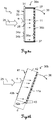
- the Fig. 1a-b each show an embodiment of a reflector assembly 1 according to the invention.
- the reflector assembly 1 each has a retroreflector 5.
- This can - as shown here - be designed for example as "all-around prism" and are thus targeted from different directions, with a reflection of the thereby directed to the prism 5 measuring radiation is parallel or coaxial.
- the retroreflector could be embodied by a retro-reflective sheeting.
- Targeting of the reflector is typically accomplished with a geodetic or industrial surveying instrument, e.g. a total station, a tachymeter or a laser tracker, carried out for the distance and position determination of the reflector 5 relative to the surveying device.
- absolute coordinates with respect to a current position of the reflector 5 or of the entire reflector arrangement 1 can be determined.
- the reflector arrangement 1 has a plurality of sensor arrangements 10a-b, by means of which, in addition to the position determination for the reflector arrangement 1, an inclination determination with respect to at least one axis is provided.
- the inclination determination is carried out by illuminating the respective sensor arrangement 10a-b and determining the angle of incidence of the illumination radiation by detecting a position of a beam impingement pattern with a sensor associated with the respective sensor arrangement 10a-b.
- a sensor is designed to determine an impact position for radiation incident on the detection surface of the sensor, for example as CCD or CMOS.
- the angle of incidence and thus the inclination in one, two or three axes can be determined.
- the illumination radiation used for illumination and tilt determination is, in particular, collimated radiation, in particular laser radiation of a defined wavelength.
- the measuring radiation which can be emitted by a geodetic surveying device (for determining the distance) can also be used for illumination and / or an additional beam source (and possibly optics) can be provided for suitable illumination.
- FIGS. 1a-b each show a plurality of sensor arrangements 10a-b, which are each positioned, for example, with an angular displacement of 60 ° about a reflector axis.
- a corresponding measuring range of approximately 60 ° of the respective sensor arrangements 10a-b it is therefore possible to obtain from any horizontal direction (within a vertical measuring range given by the sensor arrangements 10a-b), eg likewise 60 ° permissible angle of incidence relative to a detection direction of the respective sensors), the inclination determination takes place.
- a horizontal measuring range of substantially 360 ° is covered by this arrangement of the sensor arrangements 10a-b.
- the angular offset between the sensor assemblies 10a-b may alternatively be for example 30 ° or 40 °, or at least equal to or less than 90 °, so that a reliable tilt determination from substantially any horizontal directions remains possible, due to the selected structural arrangement if necessary, a (but negligible) detection gap can arise between two sensor arrangements 10a-b.
- a detailed description for inventive embodiments of the sensor arrangements 10a-b is in connection with Figs. 1c . 4a-b and 5a-b cited.
- Fig. 1c shows an exemplary embodiment of the invention according to a reflector assembly 1 according to Fig. 1a provided plurality of sensor assemblies 10a in cross section.
- a single one of these sensor arrangements 10a has a lens 13 and a sensor 11 assigned to the respective lens 13, wherein these are arranged in a specific and rigid positioning relative to each other.
- one code element each having a specific code pattern may be provided (not shown here; Figs. 4a-b and 5a-b).
- the incident radiation is influenced and / or shaped (eg, focused) by means of the code element or the lens 13 in such a way that a lighting pattern or spot, in particular with a by the code element or the lens 13 and the distance between code element / lens 13 and sensor 11 defined shape and size is generated on the sensor.
- This Strahlaufeutic Schemes thus generated depends on the angle of incidence of the illumination radiation relative to a detection direction of the sensor (orthogonal to the photoactive sensor surface or extension direction of the sensor), in particular relative to the optical axis of the lens 13, and can be determined by the sensor 11.
- FIG. 1c an inertial measuring unit 7 (IMU) provided together with the sensor arrangements 10a on a reflector arrangement 1.
- IMU 7 additionally provides inclination and orientation determination functionality to the reflector assembly 1, particularly where a change in position and orientation of and through the IMU 7 is continuously determinable.
- the IMU 7 has a magnetic compass for determining the north orientation, an inclination sensor for determining the inclination relative to a gravitational field vector and an acceleration sensor for detecting relative movements of the IMU 7 and thus also the reflector arrangement 1.
- a calibration of such an IMU 7 based on reference data which can be generated by means of a sensor arrangement of the reflector assembly 1, take place.
- An IMU is typically designed so that a fast relative position and orientation determination can be made.
- errors in measurements with an IMU accumulate over time, thereby decreasing the accuracy of the relative orientation determination.
- an inclination or orientation determination can be determined very precisely on the basis of an external reference (known propagation direction of the illumination radiation). From such a determination, corresponding reference values with respect to the inclination or orientation of the reflector arrangement can be derived, by means of which a (re) calibration of the IMU can be made.
- the reflector arrangement in particular has a processing unit and communication means for processing and comparing measured data and for exchanging information with the surveying apparatus emitting the illumination radiation.
- a user of such a reflector arrangement in conjunction with an IMU can thus, for example, mainly use the measurement data generated by the IMU (or the inclinometer) in the course of a measurement task and to use this IMU (or the inclinometer) at regular intervals (FIG. time or with regard to the number of measurements carried out) recalibrate and thus produce a high level of measuring accuracy over the entire measuring process.
- the reflector arrangement only needs, for example, by a total station irradiated with (collimated) radiation of a known propagation direction, the position of the projected code pattern on and are determined by the sensor and from the position of the projection of the pattern and the propagation direction (which can be predetermined and determined by the total station) the orientation or inclination of the Reflector arrangement can be determined.
- This particular slope is compared to the corresponding output value of the IMU and, with some deviation (eg, out of a defined tolerance range), the IMU is (re) calibrated according to the particular orientation or slope.
- Fig. 2 shows a further embodiment of a reflector arrangement 2 according to the invention with a centrally arranged retroreflector 6 for determining the position of the reflector arrangement 2, with four sensor arrangements 20a-d for determining an inclination for the reflector arrangement 2 with respect to at least two axes (pitch and yaw axes N, G) and with a number of markings 22 arranged in a known position reference for providing an orientation determination with respect to at least one third axis (rollers R around the roll axis).
- the sensor arrangements 20a-d respectively permit the inclination determination with respect to at least one axis.
- the two sensor arrangements 20a and 20b are each equipped with a code element and a line sensor, wherein upon illumination of these sensor arrangements 20a-b, the respective code of the code element is projected onto the associated line sensor and by determining the position of the projection of the code on the line sensor an inclination of the reflector assembly 2 is derivable.
- the sensor arrangement 20a aligned along the yaw axis G thus enables an inclination determination with respect to the yaw axis G (about the pitch axis N) and the sensor arrangement 20b determines the inclination with respect to the pitch axis N (about the yaw axis G).
- the detailed structure and operation of these code sensor assemblies 20a-b are described together with the Figs. 4a-b and 5a-b described.
- the two further sensor arrangements 20c and 20d each have a lens and a sensor for detecting the illumination of the arrangements 20c-d defined by the respective lens and the respective sensor incident radiation.
- an inclination of the reflector assembly 2 with respect to at least one axis can be determined.
- the sensor arrangement 20c makes it possible to determine the inclination with respect to the yaw axis G (about the pitch axis N) and with respect to the pitch axis N (about the yaw axis G) and the sensor arrangement 20d with respect to the pitch axis N (about the yaw axis G).
- the sensor arrangement 20c has an area sensor for detecting the incident illumination radiation, whereby a relative offset of the incident illumination radiation from a sensor zero point (which is illuminated, for example, in the case of a vertical incidence of the illumination radiation on the sensor arrangement and corresponds, for example, to the center of the detection area of the sensor) in two directions (X and y direction of the detection surface of the sensor) and thus the inclination with respect to two axes (N and G) can be determined with this sensor arrangement 20c.
- the respective shelves in the x and y direction of the detection surface thus represent the respective amount of inclination.
- the sensor arrangement 20c is designed such that not only the position but also the shape of the illumination cross section arising on the detection surface can be determined by means of the sensor.
- the sensor arrangement 20c is then illuminated with light having a non-rotationally symmetrical illumination divergence with respect to the beam direction (ie with respect to the propagation axis), the specific form of the resulting light spot (and the position) of the incident radiation In addition, a rough inclination determination with respect to a third axis, the roll axis done. Further explanations regarding the structure and the operation of the sensor assemblies 20c-d with a lens are in connection with the Figs. 3a-b specified.
- the sensor arrangements 20a-d provided on the reflector arrangement 2 provide the determination of the inclination with respect to the two axes N and G several times.
- one of the sensor arrangements 20a-b would be sufficient for determining the inclination with respect to at least one axis alone.
- a robustness of the generated measured values for the inclination can be achieved (for example by averaging the measured values).
- analogous or similar embodiments according to the invention with only one or at least one of the sensor arrangements 20a-b are conceivable.
- the markings 22 are designed, for example, as graphic patterns (for example with a high contrast to the background), light-emitting diodes (LEDs) or as reflectors. These markings 22 can be detected with a camera and in an image that can be generated with the camera. From a geometric position of the individual markers 22 in the image relative to each other can be on a spatial Orientation (in up to three axes) of the reflector assembly 2 are closed. For this purpose, in particular, an image processing step, for example edge extraction or brightness and / or contrast analysis, is carried out using the image information provided by the image, whereby, for example, individual image focuses for the respective markings and thus their positions in the image are determined.
- an image processing step for example edge extraction or brightness and / or contrast analysis
- the reflector assembly 1,2 can also have a fastening device by means of which the arrangement can be mounted 1,2, for example, on a pole or on a construction machine.
- a user of such a pole with the inventive reflector assembly 1, 2 can thereby carry out, for example, in conjunction with a geodetic surveying device, such as a total station, an exact position determination of a measuring point to be staked, by always illuminating the reflector arrangement 1, 2 by the surveying device in a spatial orientation of the pole can be determined exactly.
- This determination is provided by the sensor arrangement (mapping of the code pattern onto the sensor) and a corresponding evaluation unit of the total station (or the reflector arrangement).
- a position determination can be carried out by means of generally known methods for distance measurement to the intended retroreflector. For example, it is also possible for the user to determine measuring points exactly when the vertical bar is not in a vertical or an alternative, but known, orientation.
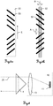
- Fig. 3a shows an embodiment of a sensor arrangement 10 of a reflector arrangement with a lens 13 and a Sensor 11.
- the illumination radiation 25 strikes the lens 13 at an incident angle ⁇ and is shaped (refracted) by it in such a way that a defined illumination cross section is thereby generated and illuminated on the sensor 11.
- the position 15 of this illumination cross section on the detection surface can be determined by the sensor 11. This determination can be made, for example, by means of a focus determination with regard to the irradiation (intensity distribution on the detection surface).
- the deposit x thus determinable thus depends on the respective angle of incidence ⁇ , which makes it possible to conclude the corresponding angle of incidence ⁇ solely by determining the deposit x and thereby inclining the sensor arrangement 10 (and thus also the reflector arrangement to which the sensor arrangement 10 is assigned ) with respect to the propagation axis of the illumination radiation 25 can be determined.
- a sensor 11 designed as a surface sensor 11 it is also possible to determine a deposit on the sensor 11 in a second direction (y-direction) and thus also the inclination in a second direction with respect to the propagation axis.
- Fig. 3b shows a further embodiment of a sensor arrangement 10.
- the sensor arrangement 10 has a cylindrical lens 13a and a line sensor 11a.
- the incident radiation 25 is focused on a plane 12 behind the lens 13a, wherein the focused radiation 25 through the cylindrical lens 13a in this plane 12 has the shape of a line 15a.
- the line sensor 11a is arranged in the plane 12 such that the extension direction of its detection surface is oriented substantially orthogonal to the resulting light line 15a (with respect to FIG Fig. 3b this means that the sensor 11a is aligned along an axis which is orthogonal to the plane of the drawing; y-direction).
- the relative offset of this illuminated area relative to the center of the detection area of the sensor 11a is proportional to the respective angle of incidence with respect to the y-direction, that is, proportional to the inclination of the sensor array 10 the y-direction relative to the propagation axis of the illumination radiation.
- this illuminated area on the sensor 11a is to be understood as the illumination cross section (beam impact area) on the sensor 11a.
- Fig. 4a shows a side view of another embodiment of an inventive Sensor arrangement 30a of a reflector arrangement according to the invention with a sensor 11 for detecting electromagnetic radiation 25 impinging on the sensor 11, in particular radiation of a defined wavelength range.
- the sensor arrangement 30a furthermore has a code element 31 with a substrate 33 and a code pattern 32 applied to the substrate 33.
- the substrate 33 is embodied such that the illumination radiation 25 used for illuminating the sensor arrangement 30a, which is embodied, for example, by the measuring radiation (for example laser radiation) of a surveying apparatus (for example total station, theodolite or laser tracker), can radiate through the substrate 33, i.
- the substrate 33 is designed to be transmissive at least with respect to the wavelength of the illumination radiation 25 or with respect to an illumination wavelength range.
- the substrate 33 may be made, for example, on a correspondingly transparent plastic or of a glass corresponding to these requirements.
- the illumination radiation is typically represented by a substantially collimated and coherent radiation.
- the code element 31 has different regions 34a, 34b, the respective dark regions 34a being impermeable to the illumination radiation 25 and the regions 34b being designed to be permeable to the illumination radiation.
- a code pattern is provided by means of the code element 31, which is provided Lighting on the sensor 11 (in the form of lines) is projected.
- a projection corresponding to the code pattern 32 is generated on the sensor 11.
- a shadow is cast on the sensor 11 according to the code pattern 32 provided by the code element 31, the position of the individual shadows 35a on the sensor 11 caused by the dark areas 33a depending on an angle of incidence ⁇ of the illumination radiation 25 (cf. Fig. 4b ).
- the code pattern 32 is imaged entirely (at least with respect to the extension in the x direction) and without offset on the sensor 11.
- the respective illuminated and dark regions 35a, 35b (generated by the projection of the code pattern 32) can be detected on the sensor 11 and their relative position on the sensor 11 can be determined. From the specific position of the individual light stripes 35b and / or shadow 35a and / or the entirety of the light 35b and dark 35a regions, the current angle of incidence ⁇ can again be deduced and a relative inclination of the sensor arrangement 30a with respect to the incident direction of the illumination radiation 25 can be concluded.
- the sensor arrangement 30a is preceded by a calibration, wherein for at least one illumination state at a defined angle of incidence ⁇ , the position of the projection of the code pattern 32 on the sensor is determined.
- the code pattern 32 executed as a line code, which has lines (gaps) of different widths and with different line spacings (definable by the size of the impermeable regions 34a) of adjacent lines through the transmissive regions 34b and whose lines are arranged substantially parallel to the detection surface of the sensor 11 , thus generated on illumination lines on the sensor 11, the positions of which can be determined by the at least with respect to the x-axis position-sensitive detecting sensor 11a on the sensor 11. If the inclination of the sensor arrangement 30a changes in the direction of inclination 36 or in the xz plane, the position of the individual lines or the totality of the lines projected onto the sensor 11 changes, from which the inclination value for the inclination direction 36 can be derived (cf. , Fig. 4b ). For example, this determination may be based on the calibration made and may be accomplished by processing known position and orientation values indicative of relative position and orientation of the code element 31 to the sensor 11.
- a spacing component 37 is provided which holds the code carrier 33 in a fixed and fixed position relative to the sensor 11. This ensures that the code pattern is always rigid in a specific and defined position and orientation and with a defined distance relative to the sensor 11 and, depending on the inclination of the arrangement 30a, the code pattern 32 is projected onto the sensor 11 with a defined offset.
- the position of the projection of the pattern on the sensor 11 is thus determined by the inclination of the sensor arrangement 30a in FIG the xz plane or with respect to the direction of inclination 36 and by the spacing component 37.
- the distance between sensor 11 and code element 31 according to the invention is between 1 mm and 10 mm and is predetermined by the spacing component 37.
- Fig. 4b shows a side view of another embodiment of a sensor arrangement 30b of a reflector arrangement according to the invention.
- the sensor arrangement 30b has a line sensor 11a (for example formed as a CCD sensor) and a code element 41, which provides a code pattern with translucent columns of different widths (gap width) and with different gap spacings.
- the code element 41 is arranged on a body 42 permeable to the illumination radiation 25. On a first end side 42a of the body 42, the sensor 11a is arranged, and on a second end side 42b of the body 42, the code element 41 is provided.
- the body 42 is further embodied such that a fixed and rigid positioning of the code element 41 relative to the sensor 11a is ensured, whereby this arrangement provides a high degree of robustness, for example against external influences (eg, impacts or thermal deformation).
- the code element 41 or code pattern is applied directly to the body 42 in the illustrated embodiment (code element 41 and body 42 are integrally formed), ie the code pattern providing column or lines are applied to the body 42 (eg printed or engraved).
- the code element 41 may be applied to the body as a film printed with the code pattern, in particular adhesively bonded thereto.
- the code element 41 is rigidly connected to the sensor 11a at a certain distance d (from 1 mm to 10 mm). This distance d can be adjusted by a respective body 42 adapted to the desired requirements. Depending on this distance d, a shadow image projected onto the sensor 11a can be superposed with a near field diffraction pattern (Fresnel diffraction).
- the distance d between the sensor 11a and code pattern is specifically chosen such that for the diffraction at the code element 41, or at the individual columns generated by the lines of the code pattern , Far field conditions apply. Instead of a pure Fresnelbeugung then Fraunhoferbeugung occurs, ie a resulting intensity distribution of the diffracted radiation on the sensor as at infinity.
- a likewise suitable diffraction pattern can be present as a diffraction transition between Fresnel diffraction and Fraunhoferbeugung, which is then spoken of a presence of the line sensor 11a relative to the code pattern 41 in a transition region.
- the arrangement and dimensioning of the translucent column are set correspondingly (eg gap spacing in relation to gap width).
- the line sensor 11a is formed at least with respect to the x-direction for position-sensitive detection of electromagnetic radiation.
- the accuracy of the detection of the radiation incident on the sensor 11a depends on at least the resolving power of the sensor and the resulting diffraction pattern, wherein a precise localization of intensity patterns with steep edges (as in Fresnel diffraction present) is more difficult and less accurate to realize than a localization of intensity patterns with flatter flanks (as in Fraunhoferbeugung or in the described diffraction transition present).
- the accuracy of the position determination of the radiation incident on the sensor 11a thus increases as it leaves the near-end diffraction range and reaches the transition region.
- the offset 43 of the projected code pattern on the sensor 11a can be determined from the detectable illumination radiation 25 and a corresponding sensor signal can be generated. From the particular offset 43 or by means of the generated sensor signal, in turn, there is an inclination (With respect to the direction of inclination 36) of the sensor arrangement 30b relative to the beam incidence direction of the illumination radiation 25 derivable, ie, the angle of incidence ⁇ can be determined.
- the Fig. 5a and Fig. 5b show a specific embodiment for a code element 55 with a code pattern 53 of a sensor arrangement of a reflector assembly according to the invention and an arrangement of the code element 55 together with a line sensor 52, on which a corresponding projection of the code element 53, a projection of the code pattern 53 takes place.
- the code pattern 53 is here made opaque to the illumination radiation, however, the optical properties of the code pattern 53 and the code pattern 53 surrounding or defining surface can be reversed.
- the intended code pattern 53 has an oblique or diagonal pattern (pattern) with different diagonal directions of the individual pattern parts (strips) with respect to the extension direction E of the code element 55.
- a first part of the pattern has a pattern orientation at a first angle relative to the extension direction E, while a second part has a pattern alignment at a second angle different from the first angle.
- the code pattern 53 projected onto the line sensor 52 shifts in the direction of the extension direction E.
- the correspondingly changed projection can be detected by the sensor 52 and therefrom an offset of the projection and an amount (and a direction) for the tilt be determined about the axis A.
- the code pattern 53 projected onto the line sensor 52 shifts in a direction orthogonal to the extension direction E.
- the correspondingly changed projection can be detected analogously by means of the sensor 52 and an offset of the projection and an amount (and one direction) for the rotation about the axis B are determined.
- the respective offset of the projection can be derived from the combination of the respectively illuminated or shadowed segments of the line sensor 52.
- Such a code pattern 53 in particular also offers the advantages in terms of accuracy as a pattern according to one of FIGS. 4a-b ,
- the code element 55 is arranged rigidly relative to the line sensor 52 in such a way that the extension direction E of the code element 55 is rectified, in particular parallel to the extension direction of the line sensor 52.
- Fig. 6 shows a further embodiment of a reflector assembly with a retroreflector 4, which is formed as a partially transparent (with respect to the radiation 25) prism and thereby a portion of the radiation 25 retro-reflected, that reflects parallel or coaxial depending on the impact position on the prism, and the remaining part the radiation 25 can be transmitted to the sensor assembly 10.
- the reflected radiation it is possible to determine the distance and position for the reflector arrangement. For example, this is done by known methods with a total station or a laser tracker, wherein the radiation 25 is emitted as measuring radiation, for example as collimated laser radiation, through the total station or the laser tracker.
- the design of the sensor assembly 10 is not limited to the variant shown here with a lens 13, but may according to any corresponding embodiment of Figures 2-5b be configured according to the invention in particular according to one of Figures 4a-5b , Furthermore, according to alternative embodiments, the retroreflector 4 (prism) may be designed for retro-reflective elements (eg as a retro-reflective film).
- the part of the radiation 25 transmitted through the prism 4 illuminates the sensor arrangement 10 such that the radiation 25 is directed onto the sensor 11 and the position of the beam spot thus generated on the sensor (illumination pattern or beam impact area) can be determined is.
- the determinable position simultaneously represents a respective inclination of the reflector arrangement relative to the propagation axis of the radiation 25 (cf. Figs. 3a-5b ).
- a signal representing the position of the projection (when using a code element instead of the lens) or the radiation on the detection surface is generated on the basis of which the inclination determination can take place.
- the reflector arrangement can have appropriate processing means for determining the inclination and / or signal transmission means by which the position information for the impinging radiation (or the signal) or an already determined inclination can be transmitted to the beam-emitting surveying apparatus (eg total station).
- the specific or there to be determined orientation (and the position information) can be further processed accordingly.
- the radiation 25 functions both as measuring radiation for the position determination and as illumination radiation for the orientation or inclination determination.
- the surveying apparatus typically has a base defining a standing axis, a structure movably connected to the base and rotatable about the standing axis relative to the base, the structure defining a tilting axis, and a structure movably connected to pivot about the tilting axis relative to the structure, especially rotatable, and for transmission Targeting unit provided by measuring radiation (in particular telescope).
- the tilting axis is substantially orthogonal to the vertical axis.
- a beam source for generating illumination radiation, in particular the measuring radiation, and an angle and distance measuring functionality are provided.
- the surveying device has a control and processing unit for controlling a targeting of the sensor arrangement and for determining a position and inclination of the sensor arrangement.
- the inclination of the sensor arrangement relative to an illumination direction (axis of the light irradiation) of the illumination radiation, in particular of the measurement radiation can be derived with respect to at least one inclination direction from an interaction of the illumination radiation, in particular the measurement radiation, and the sensor arrangement.
- the laser radiation with which a distance to a reflective target is determined, can thus be used as illumination radiation for the sensor arrangement.
- an additionally provided radiation source for the emission of the illumination radiation can be provided.
Landscapes
- Engineering & Computer Science (AREA)
- Physics & Mathematics (AREA)
- Radar, Positioning & Navigation (AREA)
- Remote Sensing (AREA)
- General Physics & Mathematics (AREA)
- Computer Networks & Wireless Communication (AREA)
- Manufacturing & Machinery (AREA)
- Electromagnetism (AREA)
- Length Measuring Devices By Optical Means (AREA)
Claims (15)
- Dispositif réflecteur (1, 2) pour la détermination de la position et/ou le marquage de points cibles, notamment pour la topométrie industrielle ou géodésique, comprenant• un rétroréflecteur (4, 5, 6) destiné à déterminer la position du dispositif réflecteur (1, 2) au moyen d'une réflexion parallèle, notamment coaxiale, de faisceau, et• un dispositif capteur (10, 10a-b, 20a-d, 30a-b),caractérisé en ce que le dispositif capteur (10, 10a-b, 20a-d, 30a-b) présente• un élément de code (31, 41, 55) doté d'un motif de code (32, 53), et• un capteur (11, 11a, 52) sensible au moins dans un domaine de longueur d'onde et possédant une direction de réception orthogonale à sa surface de détection,l'élément de code (31, 41, 55) et le capteur (11, 11a, 52) étant fixés de manière rigide selon une distance définie (d), de manière que le capteur (11, 11a, 52) puisse déterminer l'emplacement d'une projection du motif de code (32, 53) sur la surface de détection, ledit emplacement dépendant de l'angle par rapport à la direction de réception.
- Dispositif réflecteur (1, 2) selon la revendication 1,
caractérisé en ce que
la direction de réception du capteur (11, 11a, 52) est orthogonale à une direction d'extension de l'élément de code (31, 41, 55) et la distance définie est d'au moins 1 mm et d'au plus 10 mm, une direction d'extension du capteur (11, 11a, 52) étant notamment identique à la direction d'extension de l'élément de code (31, 41, 55). - Dispositif réflecteur (1, 2) selon la revendication 1 ou 2,
caractérisé en ce que
l'élément de code (31, 41, 55) présente des domaines de différentes transmittances (34a-b) au moins vis-à-vis d'un rayonnement optique (25) de longueur d'onde (λB) appartenant à l'au moins un domaine de longueur d'onde, le motif de code (32, 53) étant représenté par les domaines de différentes transmittances (34a-b), les domaines de différentes transmittances définissant notamment un motif de lignes présentant différents écarts entre les lignes et/ou différentes épaisseurs de ligne. - Dispositif réflecteur (1, 2) selon l'une des revendications 1 à 3,
caractérisé en ce que
le capteur (11, 11a, 52) est un capteur de ligne (11a, 52) ou un capteur de surface, notamment CCD ou CMOS. - Dispositif réflecteur (1, 2) selon l'une des revendications 1 à 4,
caractérisé en ce que
le dispositif réflecteur (1, 2) présente une structure porteuse, au moyen de laquelle il est possible de déterminer la position et/ou de marquer des points cibles, le rétroréflecteur (4, 5, 6) et le dispositif capteur (10, 10a-b, 20a-d, 30a-b) étant portés par la structure porteuse et présentant un positionnement mutuel connu. - Dispositif réflecteur (1, 2) selon la revendication 5,
caractérisé en ce que
la structure porteuse• constitue un instrument auxiliaire de mesure, notamment une tige de mesure ou un outil de palpage, ou• constitue un contrôleur de terrain mobile portable doté d'une unité optique de visée ou de marquage destinée à déterminer la position et/ou à marquer des points cibles, ou• possède un système d'attache destiné à fixer la structure porteuse sur l'instrument auxiliaire de mesure ou sur le contrôleur de terrain. - Dispositif réflecteur (1, 2) selon l'une des revendications 1 à 6,
caractérisé en ce que
le dispositif réflecteur (1, 2) présente au moins un dispositif capteur (10, 10a-b, 20a-d, 30a-b) supplémentaire, notamment porté par la structure porteuse, l'au moins un dispositif capteur (10, 10a-b, 20a-d, 30a-b) supplémentaire étant disposé selon une orientation et une position définies par rapport au premier dispositif capteur (10, 10a-b, 20a-d, 30a-b) afin de déterminer une inclinaison par rapport à un axe (N, G, R) supplémentaire. - Dispositif réflecteur (1, 2) selon l'une des revendications 1 à 7,
caractérisé en ce que
le dispositif réflecteur (1, 2) présente plusieurs marquages de points auxiliaires (22), notamment matérialisés par des diodes électroluminescentes ou des réflecteurs répartis les uns par rapport aux autres de manière fixe et connue dans l'espace, les marquages de points auxiliaires (22) fournissant une détermination de l'inclinaison du dispositif réflecteur (1, 2) par rapport à au moins un axe (N, G) supplémentaire, par traitement d'une image dans laquelle les marquages de points auxiliaires (22) sont captés au moins partiellement, lesdits marquages de points auxiliaires (22) fournissant notamment une détermination de l'orientation dans l'espace. - Dispositif réflecteur (1, 2) selon l'une des revendications 1 à 8,
caractérisé en ce que
le dispositif réflecteur (1, 2) présente une centrale inertielle (7) destinée à déterminer en continu une orientation et/ou une inclinaison du dispositif réflecteur (1, 2), notamment une modification de la position, de l'orientation et/ou de l'inclinaison, la centrale inertielle (7) présentant notamment un accéléromètre, un gyromètre, un inclinomètre et/ou un compas magnétique. - Dispositif réflecteur (1, 2) selon l'une des revendications 1 à 9,
caractérisé en ce que
le dispositif réflecteur (1, 2) présente un émetteur destiné à transmettre des données, l'émetteur étant notamment conçu de manière à pouvoir transmettre les données par émission d'un rayonnement électromagnétique, notamment de lumière modulée. - Procédé d'étalonnage au moyen d'un dispositif réflecteur (1, 2) conçu au moins pour la détermination de la position et/ou le marquage de points cibles et présentant• un dispositif capteur (10, 10a-b, 20a-d, 30a-b) matérialisant un dispositif capteur de référence, et• une première unité de capteur,le dispositif capteur de référence et la première unité de capteur présentant un positionnement mutuel connu, ledit procédé comportant les étapes suivantes :• obtention de données d'inclinaison de référence par rapport à un premier axe au moyen du dispositif capteur de référence (10, 10a-b, 20a-d, 30a-b), et• étalonnage de la première unité de capteur par rapport au premier axe et à partir des données d'inclinaison de référence,caractérisé en ce que
les données d'inclinaison de référence sont obtenues par• éclairage, notamment collimaté, d'un élément de code (31, 41, 55) doté d'un motif de code (32, 53) du dispositif capteur (10, 10a-b, 20a-d, 30a-b), au moyen d'un rayonnement d'éclairage,• réception du rayonnement d'éclairage par un capteur du dispositif capteur (10, 10a-b, 20a-d, 30a-b) selon un angle d'incidence (α),• détermination de l'emplacement d'une projection du motif de code en tant que zone d'incidence du rayonnement d'éclairage sur la surface de détection du capteur, ledit emplacement dépendant de l'angle par rapport à la direction de réception, et• déduction des données d'inclinaison de référence à partir de l'emplacement de la zone d'incidence du rayonnement d'éclairage et d'une direction d'incidence préalablement connue du rayonnement d'éclairage,la première unité de capteur étant notamment étalonnée à des intervalles temporels définis, notamment en continu. - Procédé d'étalonnage selon la revendication 11,
caractérisé en ce que• la première unité de capteur produit des premières données de capteur qui représentent l'inclinaison par rapport au premier axe,• il est déterminé un degré de coïncidence entre les premières données de capteur et les données d'inclinaison de référence, et• la première unité de capteur est étalonnée en fonction du degré de coïncidence, notamment de manière automatique. - Procédé d'étalonnage selon la revendication 11 ou 12,
caractérisé en ce que• la détermination de l'inclinaison par la première unité de capteur est altérée par une erreur de mesure variable, notamment croissante avec le temps, et• l'erreur de mesure est compensée par l'étalonnage de la première unité de capteur,la première unité de capteur constituant notamment une centrale inertielle (IMU, inertial measurement unit) ou un inclinomètre, notamment pluriaxial. - Utilisation d'un dispositif réflecteur (1, 2) selon l'une des revendications 1 à 10 en vue de déterminer une position et une inclinaison, au moyen des étapes suivantes :• éclairage du rétroréflecteur (4, 5, 6) au moyen d'un rayonnement de mesure (25) et détermination de la position du dispositif rétroréflecteur (1, 2) au moyen du rayonnement de mesure (25) réfléchi par le rétroréflecteur (4, 5, 6),• éclairage, notamment collimaté, du dispositif capteur (10, 10a-b, 20a-d, 30a-b), un angle d'incidence (α) étant défini par l'orientation de l'axe d'éclairage par rapport à la direction de captage du capteur du dispositif capteur (10, 10a-b, 20a-d, 30a-b),• captage d'un motif d'incidence du rayonnement provenant de l'éclairage, notamment captage de la coupe transversale de l'éclairage ou de la projection du motif de code, sur le capteur (11, 11a, 52), ledit captage étant sensible à la position par rapport à l'emplacement sur la surface de détection du capteur (11, 11a, 52), et• déduction de l'inclinaison du dispositif réflecteur (1, 2) au moins par rapport à l'axe d'éclairage, à partir de l'emplacement du motif d'incidence du rayonnement sur la surface de détection, ledit emplacement pouvant être déterminé au moyen du captage sensible à la position et dépendant de l'angle d'incidence (α).
- Produit programme d'ordinateur enregistré sur un support lisible par une machine, destiné à commander ou à exécuter un procédé d'étalonnage selon l'une des revendications 11 à 13, notamment lorsque le produit programme d'ordinateur est exécuté sur une unité de commande et de traitement d'un appareil de topométrie, notamment d'une station totale, d'un théodolite ou d'un laser de relevé.
Priority Applications (3)
| Application Number | Priority Date | Filing Date | Title |
|---|---|---|---|
| EP14158265.0A EP2916104B1 (fr) | 2014-03-07 | 2014-03-07 | Dispositif de réflecteur avec rétroréflecteur et avec dispositif de capteurs pour la détermination d'inclinaison et l'étalonnage |
| US14/641,368 US10054439B2 (en) | 2014-03-07 | 2015-03-07 | Reflector arrangement with retroreflector and with a sensor arrangement for inclination determination and calibration |
| CN201510102252.XA CN104897140B (zh) | 2014-03-07 | 2015-03-09 | 反射器装置及其校准方法和用途 |
Applications Claiming Priority (1)
| Application Number | Priority Date | Filing Date | Title |
|---|---|---|---|
| EP14158265.0A EP2916104B1 (fr) | 2014-03-07 | 2014-03-07 | Dispositif de réflecteur avec rétroréflecteur et avec dispositif de capteurs pour la détermination d'inclinaison et l'étalonnage |
Publications (2)
| Publication Number | Publication Date |
|---|---|
| EP2916104A1 EP2916104A1 (fr) | 2015-09-09 |
| EP2916104B1 true EP2916104B1 (fr) | 2018-06-27 |
Family
ID=50231046
Family Applications (1)
| Application Number | Title | Priority Date | Filing Date |
|---|---|---|---|
| EP14158265.0A Active EP2916104B1 (fr) | 2014-03-07 | 2014-03-07 | Dispositif de réflecteur avec rétroréflecteur et avec dispositif de capteurs pour la détermination d'inclinaison et l'étalonnage |
Country Status (3)
| Country | Link |
|---|---|
| US (1) | US10054439B2 (fr) |
| EP (1) | EP2916104B1 (fr) |
| CN (1) | CN104897140B (fr) |
Cited By (2)
| Publication number | Priority date | Publication date | Assignee | Title |
|---|---|---|---|---|
| WO2020010043A1 (fr) * | 2018-07-06 | 2020-01-09 | Brain Corporation | Systèmes, procédés et appareils pour étalonner des capteurs montés sur un dispositif |
| US12092771B2 (en) | 2018-07-06 | 2024-09-17 | Brain Corporation | Systems, methods and apparatuses for calibrating sensors mounted on a device |
Families Citing this family (39)
| Publication number | Priority date | Publication date | Assignee | Title |
|---|---|---|---|---|
| US10082521B2 (en) * | 2015-06-30 | 2018-09-25 | Faro Technologies, Inc. | System for measuring six degrees of freedom |
| US9903934B2 (en) | 2015-06-30 | 2018-02-27 | Faro Technologies, Inc. | Apparatus and method of measuring six degrees of freedom |
| DE102015122842B4 (de) * | 2015-12-27 | 2019-02-07 | Faro Technologies, Inc. | Verfahren zum Kalibrieren einer 3D-Messvorrichtung mittels einer Kalibrierplatte |
| US10365067B2 (en) * | 2016-10-12 | 2019-07-30 | Raytheon Company | System for aligning target sensor and weapon |
| US11709230B2 (en) * | 2017-10-12 | 2023-07-25 | John Matthews | Geodesic system and method of use |
| CN109339467B (zh) * | 2017-12-27 | 2020-11-20 | 国网山东省电力公司潍坊供电公司 | 高压电杆塔基座光学定位装置 |
| JP1680385S (fr) | 2018-05-01 | 2021-03-01 | ||
| JP1680507S (fr) | 2018-05-01 | 2021-03-08 | ||
| JP1680386S (fr) | 2018-05-01 | 2021-03-01 | ||
| JP1680387S (fr) | 2018-05-01 | 2021-03-01 | ||
| USD907085S1 (en) | 2018-05-01 | 2021-01-05 | Hamamatsu Photonics K.K. | Laser beam reflector |
| JP1680755S (fr) | 2018-05-01 | 2021-03-08 | ||
| USD903614S1 (en) | 2018-05-01 | 2020-12-01 | Hamamatsu Photonics K.K. | Laser beam reflector |
| JP1625495S (fr) | 2018-05-01 | 2019-03-18 | ||
| JP1680388S (fr) | 2018-05-01 | 2021-03-01 | ||
| JP1625135S (fr) | 2018-05-01 | 2019-03-18 | ||
| JP1639597S (fr) | 2018-05-01 | 2019-08-19 | ||
| US20200014909A1 (en) | 2018-07-03 | 2020-01-09 | Faro Technologies, Inc. | Handheld three dimensional scanner with autofocus or autoaperture |
| EP3627100B1 (fr) | 2018-09-20 | 2021-12-01 | Hexagon Technology Center GmbH | Rétroréflecteur à lentille avec un grand angle |
| EP3627101B1 (fr) | 2018-09-20 | 2021-11-03 | Hexagon Technology Center GmbH | Rétroréflecteur à capteur |
| JP7112929B2 (ja) * | 2018-09-28 | 2022-08-04 | 株式会社トプコン | 点群データ表示システム |
| EP3660451B1 (fr) * | 2018-11-28 | 2022-04-27 | Hexagon Technology Center GmbH | Module de stationnement intelligent |
| CN113167581A (zh) * | 2018-12-13 | 2021-07-23 | 莱卡地球系统公开股份有限公司 | 测量方法、测量系统和辅助测量仪器 |
| US12008679B2 (en) | 2018-12-13 | 2024-06-11 | Leica Geosystems Ag | Measurement method, measurement systems and auxiliary measurement instruments for displaying desired positions in a live image |
| EP3671115B1 (fr) * | 2018-12-17 | 2023-10-11 | Leica Geosystems AG | Système de délimitation géodésique |
| DE102018133671A1 (de) * | 2018-12-28 | 2020-07-02 | Carl Zeiss Industrielle Messtechnik Gmbh | Normal zur Kalibrierung eines Koordinatenmessgeräts |
| DE102019206480A1 (de) * | 2019-05-06 | 2020-11-12 | Audi Ag | Kraftfahrzeug mit einer äußeren Oberfläche und Verfahren zum Betrieb eines Kraftfahrzeugs |
| EP3757514B1 (fr) | 2019-06-27 | 2024-01-10 | Hexagon Technology Center GmbH | Rétroréflecteur pourvu de champ de vision de détection rotatif |
| US11619491B2 (en) | 2019-06-27 | 2023-04-04 | Hexagon Technology Center Gmbh | Retroreflectors |
| CN110608728B (zh) * | 2019-08-15 | 2021-06-29 | 中铁大桥局第七工程有限公司 | 一种开关式反射镜以及基于反射镜的测量方法 |
| EP3825659B1 (fr) | 2019-11-19 | 2023-11-08 | CSEM Centre Suisse D'electronique Et De Microtechnique SA | Capteur de position |
| CN110763168B (zh) * | 2019-12-09 | 2024-06-07 | 湖北科技学院 | 一种电梯安装时检测电梯导轨平整度的检测仪 |
| CN110954914B (zh) * | 2019-12-17 | 2023-03-31 | 北京缔科新技术研究院(有限合伙) | 一种无盲区的光量子测距仪及测距方法 |
| EP4012335A1 (fr) * | 2020-12-11 | 2022-06-15 | Leica Geosystems AG | Méthode de correction d'erreur de distance |
| JP2022188482A (ja) * | 2021-06-09 | 2022-12-21 | 株式会社トプコン | データ処理装置、データ処理方法およびデータ処理用プログラム |
| RU210087U1 (ru) * | 2021-08-31 | 2022-03-28 | Федеральное государственное бюджетное образовательное учреждение высшего образования «Казанский государственный архитектурно-строительный университет» (КазГАСУ) | Геодезическая марка |
| CN115079505B (zh) * | 2022-05-31 | 2024-05-10 | 合肥埃科光电科技股份有限公司 | 基于泰伯效应的棱镜分光多光谱相机匹配校准装置及方法 |
| EP4343280A1 (fr) | 2022-09-20 | 2024-03-27 | Hexagon Technology Center GmbH | Dispositif de surveillance pour un système optique |
| CN116123995B (zh) * | 2022-11-08 | 2024-05-31 | 中国科学院自动化研究所 | 目标点测量方法、装置、电子设备及存储介质 |
Citations (2)
| Publication number | Priority date | Publication date | Assignee | Title |
|---|---|---|---|---|
| DE102012011518B3 (de) * | 2012-06-08 | 2013-10-17 | Trimble Jena Gmbh | Geodätisches ziel und positionsbestimmungssystem |
| EP2818827A1 (fr) * | 2013-06-25 | 2014-12-31 | Kabushiki Kaisha TOPCON | Dispositif de relevé de laser |
Family Cites Families (13)
| Publication number | Priority date | Publication date | Assignee | Title |
|---|---|---|---|---|
| DE19710722C2 (de) | 1996-03-15 | 2003-06-05 | Pentax Corp | Automatische Fokussiereinrichtung für ein Fernrohr |
| JP3174551B2 (ja) | 1998-06-11 | 2001-06-11 | 旭光学工業株式会社 | 焦点調節レンズ位置検出装置 |
| JP3500077B2 (ja) | 1998-10-14 | 2004-02-23 | ペンタックス株式会社 | 視準望遠鏡の自動焦点調節機構 |
| JP4516710B2 (ja) | 1999-07-28 | 2010-08-04 | ライカ・ゲオジステームス・アクチェンゲゼルシャフト | 空間的な位置と方向づけを決定する方法と装置 |
| EP1081459B1 (fr) | 1999-08-31 | 2002-06-19 | Leica Geosystems AG | Tachéomètre-télescope |
| US7106431B2 (en) * | 2003-11-13 | 2006-09-12 | Ascension Technology Corporation | Sensor for determining the angular position of a radiating point source in two dimensions |
| EP1662278A1 (fr) | 2004-11-27 | 2006-05-31 | Leica Geosystems AG | Lentille plan-convexe ou plan-concave ayant moyen de deflection attaché |
| EP1686350A1 (fr) | 2005-01-26 | 2006-08-02 | Leica Geosystems AG | Station totale géodésique extensible de façon modulaire |
| EP1734336A1 (fr) * | 2005-06-13 | 2006-12-20 | Leica Geosystems AG | Cible d'arpentage et système d'arpentage |
| JP5558003B2 (ja) | 2006-01-13 | 2014-07-23 | ライカ・ゲオジステームス・アクチェンゲゼルシャフト | 座標測定装置 |
| US20090024325A1 (en) * | 2007-07-19 | 2009-01-22 | Scherzinger Bruno M | AINS enhanced survey instrument |
| EP2219011A1 (fr) | 2009-02-11 | 2010-08-18 | Leica Geosystems AG | Appareil de mesure géodésique |
| DE102010024014B4 (de) * | 2010-06-16 | 2016-04-21 | Trimble Jena Gmbh | Ziel für ein geodätisches Gerät |
-
2014
- 2014-03-07 EP EP14158265.0A patent/EP2916104B1/fr active Active
-
2015
- 2015-03-07 US US14/641,368 patent/US10054439B2/en active Active
- 2015-03-09 CN CN201510102252.XA patent/CN104897140B/zh active Active
Patent Citations (2)
| Publication number | Priority date | Publication date | Assignee | Title |
|---|---|---|---|---|
| DE102012011518B3 (de) * | 2012-06-08 | 2013-10-17 | Trimble Jena Gmbh | Geodätisches ziel und positionsbestimmungssystem |
| EP2818827A1 (fr) * | 2013-06-25 | 2014-12-31 | Kabushiki Kaisha TOPCON | Dispositif de relevé de laser |
Cited By (3)
| Publication number | Priority date | Publication date | Assignee | Title |
|---|---|---|---|---|
| WO2020010043A1 (fr) * | 2018-07-06 | 2020-01-09 | Brain Corporation | Systèmes, procédés et appareils pour étalonner des capteurs montés sur un dispositif |
| US12050289B2 (en) | 2018-07-06 | 2024-07-30 | Brain Corporation | Systems, methods and apparatuses for calibrating sensors mounted on a device |
| US12092771B2 (en) | 2018-07-06 | 2024-09-17 | Brain Corporation | Systems, methods and apparatuses for calibrating sensors mounted on a device |
Also Published As
| Publication number | Publication date |
|---|---|
| CN104897140B (zh) | 2018-02-02 |
| CN104897140A (zh) | 2015-09-09 |
| EP2916104A1 (fr) | 2015-09-09 |
| US20150253137A1 (en) | 2015-09-10 |
| US10054439B2 (en) | 2018-08-21 |
Similar Documents
| Publication | Publication Date | Title |
|---|---|---|
| EP2916104B1 (fr) | Dispositif de réflecteur avec rétroréflecteur et avec dispositif de capteurs pour la détermination d'inclinaison et l'étalonnage | |
| EP2810019B1 (fr) | Système de mesure doté d'un appareil de mesure et d'un module de balayage | |
| EP2875383B1 (fr) | Appareil de suivi laser avec unité de calibrage pour calibrage automatique | |
| EP2810020B1 (fr) | Dispositif d'arpentage doté d'une fonctionnalité de balayage et d'un mode de mesure à point unique | |
| EP3264034B1 (fr) | Appareil de mesure avec système de mesure de hauteur et procédé de mesure d'une hauteur | |
| EP2405236B1 (fr) | Appareil de mesure géodésique doté d'une fonction haute précision de ciblage de point cible | |
| EP2805180B1 (fr) | Appareil de suivi laser doté d'une fonctionnalité pour la préparation de cibles graphiques | |
| EP2787322B1 (fr) | Référencement géodésique de nuages de points | |
| EP2788791B1 (fr) | Appareil de suivi laser doté de détecteurs sensibles à la position pour la recherche d'une cible | |
| EP2707745B1 (fr) | Procédé de calibrage pour un appareil doté d'une fonctionnalité de balayage | |
| EP2746806B1 (fr) | Appareil de suivi laser à calibrage automatique et procédé de calibrage automatique | |
| EP1703300A1 (fr) | Procédé et dispositif pour déterminer la position et l'orientation d'un objet | |
| DE19941638C1 (de) | Geodätisches Gerät mit Laseranordnung | |
| EP2801841A1 (fr) | Appareil de suivi laser comprenant une unité d'enregistrement d'objectif pour le suivi d'un objectif et une détection d'orientation | |
| EP3627101B1 (fr) | Rétroréflecteur à capteur | |
| EP2893371B1 (fr) | Appareil de suivi laser avec procédé de représentation hybride destiné à agrandir la portée de mesure | |
| EP3627100B1 (fr) | Rétroréflecteur à lentille avec un grand angle |
Legal Events
| Date | Code | Title | Description |
|---|---|---|---|
| PUAI | Public reference made under article 153(3) epc to a published international application that has entered the european phase |
Free format text: ORIGINAL CODE: 0009012 |
|
| AK | Designated contracting states |
Kind code of ref document: A1 Designated state(s): AL AT BE BG CH CY CZ DE DK EE ES FI FR GB GR HR HU IE IS IT LI LT LU LV MC MK MT NL NO PL PT RO RS SE SI SK SM TR |
|
| AX | Request for extension of the european patent |
Extension state: BA ME |
|
| 17P | Request for examination filed |
Effective date: 20160224 |
|
| RBV | Designated contracting states (corrected) |
Designated state(s): AL AT BE BG CH CY CZ DE DK EE ES FI FR GB GR HR HU IE IS IT LI LT LU LV MC MK MT NL NO PL PT RO RS SE SI SK SM TR |
|
| 17Q | First examination report despatched |
Effective date: 20160804 |
|
| STAA | Information on the status of an ep patent application or granted ep patent |
Free format text: STATUS: EXAMINATION IS IN PROGRESS |
|
| RIC1 | Information provided on ipc code assigned before grant |
Ipc: G01C 25/00 20060101ALI20171127BHEP Ipc: G01C 15/06 20060101ALI20171127BHEP Ipc: G01C 15/00 20060101AFI20171127BHEP |
|
| GRAP | Despatch of communication of intention to grant a patent |
Free format text: ORIGINAL CODE: EPIDOSNIGR1 |
|
| STAA | Information on the status of an ep patent application or granted ep patent |
Free format text: STATUS: GRANT OF PATENT IS INTENDED |
|
| INTG | Intention to grant announced |
Effective date: 20180129 |
|
| GRAS | Grant fee paid |
Free format text: ORIGINAL CODE: EPIDOSNIGR3 |
|
| GRAA | (expected) grant |
Free format text: ORIGINAL CODE: 0009210 |
|
| STAA | Information on the status of an ep patent application or granted ep patent |
Free format text: STATUS: THE PATENT HAS BEEN GRANTED |
|
| AK | Designated contracting states |
Kind code of ref document: B1 Designated state(s): AL AT BE BG CH CY CZ DE DK EE ES FI FR GB GR HR HU IE IS IT LI LT LU LV MC MK MT NL NO PL PT RO RS SE SI SK SM TR |
|
| REG | Reference to a national code |
Ref country code: GB Ref legal event code: FG4D Free format text: NOT ENGLISH |
|
| REG | Reference to a national code |
Ref country code: AT Ref legal event code: REF Ref document number: 1012721 Country of ref document: AT Kind code of ref document: T Effective date: 20180715 |
|
| REG | Reference to a national code |
Ref country code: IE Ref legal event code: FG4D Free format text: LANGUAGE OF EP DOCUMENT: GERMAN |
|
| REG | Reference to a national code |
Ref country code: DE Ref legal event code: R096 Ref document number: 502014008633 Country of ref document: DE |
|
| REG | Reference to a national code |
Ref country code: CH Ref legal event code: NV Representative=s name: KAMINSKI HARMANN PATENTANWAELTE AG, LI |
|
| REG | Reference to a national code |
Ref country code: SE Ref legal event code: TRGR |
|
| REG | Reference to a national code |
Ref country code: NL Ref legal event code: FP |
|
| PG25 | Lapsed in a contracting state [announced via postgrant information from national office to epo] |
Ref country code: NO Free format text: LAPSE BECAUSE OF FAILURE TO SUBMIT A TRANSLATION OF THE DESCRIPTION OR TO PAY THE FEE WITHIN THE PRESCRIBED TIME-LIMIT Effective date: 20180927 Ref country code: FI Free format text: LAPSE BECAUSE OF FAILURE TO SUBMIT A TRANSLATION OF THE DESCRIPTION OR TO PAY THE FEE WITHIN THE PRESCRIBED TIME-LIMIT Effective date: 20180627 Ref country code: BG Free format text: LAPSE BECAUSE OF FAILURE TO SUBMIT A TRANSLATION OF THE DESCRIPTION OR TO PAY THE FEE WITHIN THE PRESCRIBED TIME-LIMIT Effective date: 20180927 Ref country code: LT Free format text: LAPSE BECAUSE OF FAILURE TO SUBMIT A TRANSLATION OF THE DESCRIPTION OR TO PAY THE FEE WITHIN THE PRESCRIBED TIME-LIMIT Effective date: 20180627 |
|
| REG | Reference to a national code |
Ref country code: LT Ref legal event code: MG4D |
|
| PG25 | Lapsed in a contracting state [announced via postgrant information from national office to epo] |
Ref country code: LV Free format text: LAPSE BECAUSE OF FAILURE TO SUBMIT A TRANSLATION OF THE DESCRIPTION OR TO PAY THE FEE WITHIN THE PRESCRIBED TIME-LIMIT Effective date: 20180627 Ref country code: GR Free format text: LAPSE BECAUSE OF FAILURE TO SUBMIT A TRANSLATION OF THE DESCRIPTION OR TO PAY THE FEE WITHIN THE PRESCRIBED TIME-LIMIT Effective date: 20180928 Ref country code: HR Free format text: LAPSE BECAUSE OF FAILURE TO SUBMIT A TRANSLATION OF THE DESCRIPTION OR TO PAY THE FEE WITHIN THE PRESCRIBED TIME-LIMIT Effective date: 20180627 Ref country code: RS Free format text: LAPSE BECAUSE OF FAILURE TO SUBMIT A TRANSLATION OF THE DESCRIPTION OR TO PAY THE FEE WITHIN THE PRESCRIBED TIME-LIMIT Effective date: 20180627 |
|
| PG25 | Lapsed in a contracting state [announced via postgrant information from national office to epo] |
Ref country code: IS Free format text: LAPSE BECAUSE OF FAILURE TO SUBMIT A TRANSLATION OF THE DESCRIPTION OR TO PAY THE FEE WITHIN THE PRESCRIBED TIME-LIMIT Effective date: 20181027 Ref country code: PL Free format text: LAPSE BECAUSE OF FAILURE TO SUBMIT A TRANSLATION OF THE DESCRIPTION OR TO PAY THE FEE WITHIN THE PRESCRIBED TIME-LIMIT Effective date: 20180627 Ref country code: EE Free format text: LAPSE BECAUSE OF FAILURE TO SUBMIT A TRANSLATION OF THE DESCRIPTION OR TO PAY THE FEE WITHIN THE PRESCRIBED TIME-LIMIT Effective date: 20180627 Ref country code: RO Free format text: LAPSE BECAUSE OF FAILURE TO SUBMIT A TRANSLATION OF THE DESCRIPTION OR TO PAY THE FEE WITHIN THE PRESCRIBED TIME-LIMIT Effective date: 20180627 Ref country code: CZ Free format text: LAPSE BECAUSE OF FAILURE TO SUBMIT A TRANSLATION OF THE DESCRIPTION OR TO PAY THE FEE WITHIN THE PRESCRIBED TIME-LIMIT Effective date: 20180627 Ref country code: SK Free format text: LAPSE BECAUSE OF FAILURE TO SUBMIT A TRANSLATION OF THE DESCRIPTION OR TO PAY THE FEE WITHIN THE PRESCRIBED TIME-LIMIT Effective date: 20180627 |
|
| PG25 | Lapsed in a contracting state [announced via postgrant information from national office to epo] |
Ref country code: ES Free format text: LAPSE BECAUSE OF FAILURE TO SUBMIT A TRANSLATION OF THE DESCRIPTION OR TO PAY THE FEE WITHIN THE PRESCRIBED TIME-LIMIT Effective date: 20180627 Ref country code: SM Free format text: LAPSE BECAUSE OF FAILURE TO SUBMIT A TRANSLATION OF THE DESCRIPTION OR TO PAY THE FEE WITHIN THE PRESCRIBED TIME-LIMIT Effective date: 20180627 Ref country code: IT Free format text: LAPSE BECAUSE OF FAILURE TO SUBMIT A TRANSLATION OF THE DESCRIPTION OR TO PAY THE FEE WITHIN THE PRESCRIBED TIME-LIMIT Effective date: 20180627 |
|
| REG | Reference to a national code |
Ref country code: DE Ref legal event code: R097 Ref document number: 502014008633 Country of ref document: DE |
|
| PLBE | No opposition filed within time limit |
Free format text: ORIGINAL CODE: 0009261 |
|
| STAA | Information on the status of an ep patent application or granted ep patent |
Free format text: STATUS: NO OPPOSITION FILED WITHIN TIME LIMIT |
|
| PG25 | Lapsed in a contracting state [announced via postgrant information from national office to epo] |
Ref country code: DK Free format text: LAPSE BECAUSE OF FAILURE TO SUBMIT A TRANSLATION OF THE DESCRIPTION OR TO PAY THE FEE WITHIN THE PRESCRIBED TIME-LIMIT Effective date: 20180627 |
|
| 26N | No opposition filed |
Effective date: 20190328 |
|
| PG25 | Lapsed in a contracting state [announced via postgrant information from national office to epo] |
Ref country code: SI Free format text: LAPSE BECAUSE OF FAILURE TO SUBMIT A TRANSLATION OF THE DESCRIPTION OR TO PAY THE FEE WITHIN THE PRESCRIBED TIME-LIMIT Effective date: 20180627 |
|
| PG25 | Lapsed in a contracting state [announced via postgrant information from national office to epo] |
Ref country code: MC Free format text: LAPSE BECAUSE OF FAILURE TO SUBMIT A TRANSLATION OF THE DESCRIPTION OR TO PAY THE FEE WITHIN THE PRESCRIBED TIME-LIMIT Effective date: 20180627 |
|
| PG25 | Lapsed in a contracting state [announced via postgrant information from national office to epo] |
Ref country code: LU Free format text: LAPSE BECAUSE OF NON-PAYMENT OF DUE FEES Effective date: 20190307 Ref country code: AL Free format text: LAPSE BECAUSE OF FAILURE TO SUBMIT A TRANSLATION OF THE DESCRIPTION OR TO PAY THE FEE WITHIN THE PRESCRIBED TIME-LIMIT Effective date: 20180627 |
|
| REG | Reference to a national code |
Ref country code: BE Ref legal event code: MM Effective date: 20190331 |
|
| PG25 | Lapsed in a contracting state [announced via postgrant information from national office to epo] |
Ref country code: IE Free format text: LAPSE BECAUSE OF NON-PAYMENT OF DUE FEES Effective date: 20190307 |
|
| PG25 | Lapsed in a contracting state [announced via postgrant information from national office to epo] |
Ref country code: BE Free format text: LAPSE BECAUSE OF NON-PAYMENT OF DUE FEES Effective date: 20190331 |
|
| PG25 | Lapsed in a contracting state [announced via postgrant information from national office to epo] |
Ref country code: TR Free format text: LAPSE BECAUSE OF FAILURE TO SUBMIT A TRANSLATION OF THE DESCRIPTION OR TO PAY THE FEE WITHIN THE PRESCRIBED TIME-LIMIT Effective date: 20180627 |
|
| PGFP | Annual fee paid to national office [announced via postgrant information from national office to epo] |
Ref country code: NL Payment date: 20200319 Year of fee payment: 7 Ref country code: SE Payment date: 20200323 Year of fee payment: 7 |
|
| PGFP | Annual fee paid to national office [announced via postgrant information from national office to epo] |
Ref country code: CH Payment date: 20200319 Year of fee payment: 7 |
|
| PG25 | Lapsed in a contracting state [announced via postgrant information from national office to epo] |
Ref country code: MT Free format text: LAPSE BECAUSE OF FAILURE TO SUBMIT A TRANSLATION OF THE DESCRIPTION OR TO PAY THE FEE WITHIN THE PRESCRIBED TIME-LIMIT Effective date: 20180627 Ref country code: PT Free format text: LAPSE BECAUSE OF FAILURE TO SUBMIT A TRANSLATION OF THE DESCRIPTION OR TO PAY THE FEE WITHIN THE PRESCRIBED TIME-LIMIT Effective date: 20181029 |
|
| REG | Reference to a national code |
Ref country code: AT Ref legal event code: MM01 Ref document number: 1012721 Country of ref document: AT Kind code of ref document: T Effective date: 20190307 |
|
| PG25 | Lapsed in a contracting state [announced via postgrant information from national office to epo] |
Ref country code: AT Free format text: LAPSE BECAUSE OF NON-PAYMENT OF DUE FEES Effective date: 20190307 |
|
| PG25 | Lapsed in a contracting state [announced via postgrant information from national office to epo] |
Ref country code: CY Free format text: LAPSE BECAUSE OF FAILURE TO SUBMIT A TRANSLATION OF THE DESCRIPTION OR TO PAY THE FEE WITHIN THE PRESCRIBED TIME-LIMIT Effective date: 20180627 |
|
| PG25 | Lapsed in a contracting state [announced via postgrant information from national office to epo] |
Ref country code: HU Free format text: LAPSE BECAUSE OF FAILURE TO SUBMIT A TRANSLATION OF THE DESCRIPTION OR TO PAY THE FEE WITHIN THE PRESCRIBED TIME-LIMIT; INVALID AB INITIO Effective date: 20140307 |
|
| REG | Reference to a national code |
Ref country code: CH Ref legal event code: PL |
|
| REG | Reference to a national code |
Ref country code: NL Ref legal event code: MM Effective date: 20210401 |
|
| PG25 | Lapsed in a contracting state [announced via postgrant information from national office to epo] |
Ref country code: SE Free format text: LAPSE BECAUSE OF NON-PAYMENT OF DUE FEES Effective date: 20210308 Ref country code: NL Free format text: LAPSE BECAUSE OF NON-PAYMENT OF DUE FEES Effective date: 20210401 Ref country code: CH Free format text: LAPSE BECAUSE OF NON-PAYMENT OF DUE FEES Effective date: 20210331 Ref country code: LI Free format text: LAPSE BECAUSE OF NON-PAYMENT OF DUE FEES Effective date: 20210331 |
|
| PG25 | Lapsed in a contracting state [announced via postgrant information from national office to epo] |
Ref country code: MK Free format text: LAPSE BECAUSE OF FAILURE TO SUBMIT A TRANSLATION OF THE DESCRIPTION OR TO PAY THE FEE WITHIN THE PRESCRIBED TIME-LIMIT Effective date: 20180627 |
|
| PGFP | Annual fee paid to national office [announced via postgrant information from national office to epo] |
Ref country code: DE Payment date: 20240320 Year of fee payment: 11 Ref country code: GB Payment date: 20240320 Year of fee payment: 11 |
|
| PGFP | Annual fee paid to national office [announced via postgrant information from national office to epo] |
Ref country code: FR Payment date: 20240328 Year of fee payment: 11 |