EP2916075A1 - Method and system for supplying a fuel into a combustion chamber - Google Patents
Method and system for supplying a fuel into a combustion chamber Download PDFInfo
- Publication number
- EP2916075A1 EP2916075A1 EP14157773.4A EP14157773A EP2916075A1 EP 2916075 A1 EP2916075 A1 EP 2916075A1 EP 14157773 A EP14157773 A EP 14157773A EP 2916075 A1 EP2916075 A1 EP 2916075A1
- Authority
- EP
- European Patent Office
- Prior art keywords
- fuel
- mixture
- combustion chamber
- pressure
- supercritical pressure
- Prior art date
- Legal status (The legal status is an assumption and is not a legal conclusion. Google has not performed a legal analysis and makes no representation as to the accuracy of the status listed.)
- Granted
Links
Images



Classifications
-
- F—MECHANICAL ENGINEERING; LIGHTING; HEATING; WEAPONS; BLASTING
- F23—COMBUSTION APPARATUS; COMBUSTION PROCESSES
- F23K—FEEDING FUEL TO COMBUSTION APPARATUS
- F23K5/00—Feeding or distributing other fuel to combustion apparatus
- F23K5/02—Liquid fuel
- F23K5/08—Preparation of fuel
- F23K5/10—Mixing with other fluids
-
- C—CHEMISTRY; METALLURGY
- C10—PETROLEUM, GAS OR COKE INDUSTRIES; TECHNICAL GASES CONTAINING CARBON MONOXIDE; FUELS; LUBRICANTS; PEAT
- C10L—FUELS NOT OTHERWISE PROVIDED FOR; NATURAL GAS; SYNTHETIC NATURAL GAS OBTAINED BY PROCESSES NOT COVERED BY SUBCLASSES C10G OR C10K; LIQUIFIED PETROLEUM GAS; USE OF ADDITIVES TO FUELS OR FIRES; FIRE-LIGHTERS
- C10L3/00—Gaseous fuels; Natural gas; Synthetic natural gas obtained by processes not covered by subclass C10G, C10K; Liquefied petroleum gas
- C10L3/003—Additives for gaseous fuels
-
- C—CHEMISTRY; METALLURGY
- C10—PETROLEUM, GAS OR COKE INDUSTRIES; TECHNICAL GASES CONTAINING CARBON MONOXIDE; FUELS; LUBRICANTS; PEAT
- C10G—CRACKING HYDROCARBON OILS; PRODUCTION OF LIQUID HYDROCARBON MIXTURES, e.g. BY DESTRUCTIVE HYDROGENATION, OLIGOMERISATION, POLYMERISATION; RECOVERY OF HYDROCARBON OILS FROM OIL-SHALE, OIL-SAND, OR GASES; REFINING MIXTURES MAINLY CONSISTING OF HYDROCARBONS; REFORMING OF NAPHTHA; MINERAL WAXES
- C10G2300/00—Aspects relating to hydrocarbon processing covered by groups C10G1/00 - C10G99/00
- C10G2300/20—Characteristics of the feedstock or the products
- C10G2300/30—Physical properties of feedstocks or products
- C10G2300/302—Viscosity
-
- F—MECHANICAL ENGINEERING; LIGHTING; HEATING; WEAPONS; BLASTING
- F23—COMBUSTION APPARATUS; COMBUSTION PROCESSES
- F23G—CREMATION FURNACES; CONSUMING WASTE PRODUCTS BY COMBUSTION
- F23G2201/00—Pretreatment
- F23G2201/70—Blending
-
- F—MECHANICAL ENGINEERING; LIGHTING; HEATING; WEAPONS; BLASTING
- F23—COMBUSTION APPARATUS; COMBUSTION PROCESSES
- F23G—CREMATION FURNACES; CONSUMING WASTE PRODUCTS BY COMBUSTION
- F23G2209/00—Specific waste
- F23G2209/10—Liquid waste
- F23G2209/102—Waste oil
-
- F—MECHANICAL ENGINEERING; LIGHTING; HEATING; WEAPONS; BLASTING
- F23—COMBUSTION APPARATUS; COMBUSTION PROCESSES
- F23K—FEEDING FUEL TO COMBUSTION APPARATUS
- F23K2201/00—Pretreatment of solid fuel
- F23K2201/50—Blending
- F23K2201/503—Blending with non-combustible liquids to prepare slurries
Definitions
- the present invention relates to a method and system for supplying a fuel into a combustion chamber.
- the combustion chamber is for example the combustion chamber of a boiler or furnace for industrial applications.
- the combustion chamber can be an oxy fuel combustion chamber, i.e. a combustion chamber that is supplied with a fuel and substantially pure oxygen, this is anyhow not needed and the combustion chamber can be supplied with a fuel and air.
- the combustion chamber can also be supplied with recirculated flue gas, but this is also not mandatory.
- the fuel is a high viscosity fluid, i.e. a fluid that alone is not able to pass through the ducts and injectors of the combustion chamber, but needs appropriate helps for this.
- the fuel is heavy residue.
- Crude oil undergoes a number of treatments in order to separate different products from it, such as for example, liquefied petroleum gas, gasoline, diesel oil, kerosene, etc.; the remaining of these treatments is the so called heavy residue, that is a high viscosity product that at atmospheric conditions becomes solid.
- the heavy residue is heated and mixed with kerosene and/or water in order to obtain a low viscosity fluid.
- Heavy residue must be heated up to a temperature very close to its coking temperature. At the coking temperature, the heavy residue forms solid coke deposits that accumulate in piping and injectors, blocking them.
- the coking temperature for the heavy residue can begin already at temperatures as low as 200-250°C depending on the originating crude feedstock. When the heavy residue is heated up close to the coking temperature, there is the risk that some fractions of the heavy residue start to coke due to an uneven mixture of the heavy residue.
- the known solution requires the use of highly expensive fuel, such as kerosene, or high expensive fluid, such as water (in some countries water can be more expensive than oil).
- An aspect of the invention includes providing a method and system that avoid heating of the heavy residue or require a heating up to a temperature well far apart from the coking temperature, such that cocking is prevented.
- Another aspect of the invention includes providing a method and system that avoid or at least limit the use of expensive fuel (such as kerosene) or fluid (such as water) together with the heavy residue.
- expensive fuel such as kerosene
- fluid such as water
- the described solution addresses heavy residue being fuels that have a viscosity of more than 150 cSt at a temperature of 100°C.
- the combustion chamber is a part of a boiler for a power plant or an industrial furnace.
- the combustion chamber 1 combusts a fuel and generates flue gas 2 that is supplied to a flue gas treatment system 3.
- the flue gas treatment system 3 can be of any kind and, for example, it can include a compressor 5, a mercury removal unit 6 and a drier 7. Heat exchangers 8, 9 are preferably provided upstream of the mercury removal unit 6 and drier 7.
- the flue gas is supplied into a separation unit 10, where the CO 2 is separated from other gas.
- the CO 2 is thus supplied to a compressor 12a-c (for example a multi stage, intercooled compressor) where it is compressed up to or above the supercritical pressure, and then to a pump 13 (but this pump is not needed and it is used according to the design) to be further compressed for storage at 14.
- a compressor 12a-c for example a multi stage, intercooled compressor
- the separation unit 10 can be of any type, for example figure 2 shows a scheme in which the separation unit includes two stages 15a, 15b of condensation by cooling.
- CO 2 that condenses 16a, 16b at each condensation stage 15a, 15b is also used as cooling medium.
- gas 17 being the flue gas deprived of CO 2 is expanded and used as cooling medium at the condensation stages 15a, 15b; the gas 17 is then vented.
- a heat exchanger 18 can be provided (it is not mandatory and is provided according to the specific design).
- the heat exchanger 18 is used for cooling the CO 2 compressed at the compressor 12a-c.
- the system 1 comprises a fuel supply 20, a supercritical pressure CO 2 supply 22, a mixing system 24 for forming a mixture of fuel and supercritical pressure CO 2 , injectors 26 connected to the mixing system 24 for injecting the mixture into the combustion chamber 1.
- the mixing system can be defined by the converging pipes through which supercritical pressure CO 2 and fuel pass through, or by a dedicated mixer or tank.
- the combustion chamber has a pressure lower than the CO 2 critical pressure.
- the system preferably has (but this is not needed and depends on the particular design and conditions) at least a heat exchanger for heating the mixture and/or the fuel and/or the supercritical pressure CO 2 .
- the heat exchangers can include:
- heat exchangers 27a, 27b, 28, 29 can be provided, in addition any combination of heat exchangers 27a, 27b, 28, 29 is possible.
- the supercritical pressure CO 2 can be supplied from the line that forwards the CO 2 to the storage 14, from a position upstream the pump 13 or downstream the pump 13.
- the supercritical pressure CO 2 supply 22 can depart from a position between the compressor 12a-c and the heat exchanger 18 ( figures 1 and 2 ) and/or from a position between heat exchanger 18 and the pump 13 and/or from a position between the pump 13 and the storage 14 (figure 14).
- flue gas 2 is generated from the combustion of the fuel.
- the flue gas is compressed at the compressor 5 and then the flue gas undergoes cooling at the heat exchanger 8, mercury removal at the mercury removal unit 6, cooling at the heat exchanger 9, water removal at the drier 7.
- the flue gas is supplied into the separation unit 10 where CO 2 is separated from the other gas 17 (such as nitrogen, argon, etc.).
- the gas 17 is vented into the atmosphere and the CO 2 (that is still gas) is supplied to the compressor 12a-c (usually a multistage, intercooled compressor that is used to prepare the CO 2 for storage).
- the CO 2 is compressed up to or above the critical pressure (critical pressure 72.9 bar or 7.39 MPa); then at the heat exchanger 18 the CO 2 compressed at or above the critical pressure is cooled.
- the CO 2 can be either:
- the supercritical CO 2 i.e. CO 2 at or above the critical pressure and at or above the critical temperature (304.25 K) has a high density and can thus be pumped.
- the CO 2 at or above the critical pressure and below the critical temperature (304.25 K) has a high density and can be pumped. This region is sometimes called the dense phase region.
- the supercritical CO 2 or CO 2 in the dense phase region is further compressed for storage. Downstream the pump 13 the pressure of the supercritical CO 2 is 100 bar or more.
- Supercritical pressure CO 2 (the temperature of the supercritical pressure CO 2 can be the supercritical temperature, or it can be above or below the supercritical temperature) is thus preferably supplied from a position downstream the compressor 12a-c and upstream or downstream the pump 13 (when provided) to the mixing system 24.
- heavy residue is supplied from the fuel supply 20 to the mixing system 24.
- the mixing system 24 the heavy residue and supercritical pressure CO 2 form a mixture.
- the supercritical pressure CO 2 is a very good solvent for heavy residue. For this reason, the mixture of heavy residue and supercritical pressure CO 2 can contain a large amount of CO 2 , such that the viscosity of the mixture allows injection in the combustion chamber 1.
- the mixture (the temperature of the mixture after mixing is typically below 60°C) can be heated at the heat exchanger 29.
- the supercritical pressure CO 2 and/or the heavy residue can be heated at the heat exchangers 27a, 27b, 28, in such a way that that the temperature of the mixture containing the heavy residue and the supercritical pressure CO 2 falls in the preferred temperature range.
- the preferred range for the temperature of the mixture is between 50-160°C, with a more preferred range between 60-90°C; the temperature is thus well below the cocking temperature for the heavy residue.
- the mixture is supplied to the injectors 26 and is injected into the combustion chamber 1.
- the pressure of the mixture (containing supercritical pressure CO 2 and heavy residue) suddenly drops.
- the pressure drop causes a sudden expansion of the CO 2 (up to 10 times or more). Since the CO 2 is mixed with the heavy residue, this expansion helps atomization of heavy residue and its dispersion through the combustion chamber 1. Atomization and dispersion through the combustion chamber 1 help a complete and clean combustion.
- Figure 5 shows the injectors 26 with nozzles 30, jets of mixtures 31 and the expanding CO 2 that promotes heavy residue dispersion through the combustion chamber 1 and atomization.
- the fuel such as heavy residue atomized and dispersed through the combustion chamber can thus combust with air or oxygen.
- Figure 6 shows an example of the nozzle 30; in this figure the arrow indicates the flow through the nozzle 30. In addition figure 6 shows the convergent-divergent design of the nozzle 30 that helps preventing excessive erosion.
- the present invention also refers to a method for supplying a fuel into a combustion chamber.
- the method comprises mixing the fuel with supercritical pressure CO 2 forming a mixture and injecting the mixture into a combustion chamber having a pressure lower than the CO 2 critical pressure.
- the mixture contains between 10-70% by weight of supercritical pressure CO 2 and preferably between 15-25% by weight of supercritical pressure CO 2 .
- the mixture and/or the fuel and/or the supercritical pressure CO 2 can be heated in order to obtain a heated mixture, whose viscosity is preferably between 15-30 centipoise. This viscosity allows easy injection of the heavy residue through the injector 26.
- the temperature of the heated mixture is between 50-160°C and preferably between 60-90°C.
- the mixture and/or the fuel and/or the supercritical pressure CO 2 are heated by cooling the flue gas.
Landscapes
- Chemical & Material Sciences (AREA)
- Engineering & Computer Science (AREA)
- Oil, Petroleum & Natural Gas (AREA)
- Chemical Kinetics & Catalysis (AREA)
- General Chemical & Material Sciences (AREA)
- Organic Chemistry (AREA)
- Combustion & Propulsion (AREA)
- Mechanical Engineering (AREA)
- General Engineering & Computer Science (AREA)
Abstract
Description
- The present invention relates to a method and system for supplying a fuel into a combustion chamber. The combustion chamber is for example the combustion chamber of a boiler or furnace for industrial applications. The combustion chamber can be an oxy fuel combustion chamber, i.e. a combustion chamber that is supplied with a fuel and substantially pure oxygen, this is anyhow not needed and the combustion chamber can be supplied with a fuel and air. In addition, the combustion chamber can also be supplied with recirculated flue gas, but this is also not mandatory.
- The fuel is a high viscosity fluid, i.e. a fluid that alone is not able to pass through the ducts and injectors of the combustion chamber, but needs appropriate helps for this. For example the fuel is heavy residue.
- Crude oil undergoes a number of treatments in order to separate different products from it, such as for example, liquefied petroleum gas, gasoline, diesel oil, kerosene, etc.; the remaining of these treatments is the so called heavy residue, that is a high viscosity product that at atmospheric conditions becomes solid.
- Traditionally, heavy residue is used in boilers as a fuel, for example in power plants.
- In order to get a product that can be handled, such as for example injected and atomized through injectors into the combustion chamber of a boiler, the heavy residue is heated and mixed with kerosene and/or water in order to obtain a low viscosity fluid.
- This known solution has some disadvantages.
- Heavy residue must be heated up to a temperature very close to its coking temperature. At the coking temperature, the heavy residue forms solid coke deposits that accumulate in piping and injectors, blocking them. The coking temperature for the heavy residue can begin already at temperatures as low as 200-250°C depending on the originating crude feedstock. When the heavy residue is heated up close to the coking temperature, there is the risk that some fractions of the heavy residue start to coke due to an uneven mixture of the heavy residue.
- In addition, the known solution requires the use of highly expensive fuel, such as kerosene, or high expensive fluid, such as water (in some countries water can be more expensive than oil).
- An aspect of the invention includes providing a method and system that avoid heating of the heavy residue or require a heating up to a temperature well far apart from the coking temperature, such that cocking is prevented.
- Another aspect of the invention includes providing a method and system that avoid or at least limit the use of expensive fuel (such as kerosene) or fluid (such as water) together with the heavy residue.
- These and further aspects are attained by providing a method and a system in accordance with the accompanying claims.
- The described solution addresses heavy residue being fuels that have a viscosity of more than 150 cSt at a temperature of 100°C.
- Further characteristics and advantages will be more apparent from the description of a preferred but non-exclusive embodiment of the method and system, illustrated by way of non-limiting example in the accompanying drawings, in which:
-
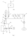
Figure 1 shows an example of the system in a first embodiment; -
Figure 2 shows an example of the system in a second embodiment; -
Figure 3 shows an example of the system in a third embodiment; -
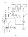
Figure 4 shows an example of the system in a fourth embodiment; -
Figure 5 shows an example of injection, and -
Figure 6 shows a nozzle. - In the following the system for supplying a fuel such as heavy residue (i.e. a fuel having a viscosity equal to or greater than 150 cSt at a temperature of 100°C) into a
combustion chamber 1 is described first. - The combustion chamber is a part of a boiler for a power plant or an industrial furnace.
- The
combustion chamber 1 combusts a fuel and generatesflue gas 2 that is supplied to a fluegas treatment system 3. - The flue
gas treatment system 3 can be of any kind and, for example, it can include acompressor 5, a mercury removal unit 6 and adrier 7.Heat exchangers drier 7. - From the
drier 7 the flue gas is supplied into aseparation unit 10, where the CO2 is separated from other gas. The CO2 is thus supplied to acompressor 12a-c (for example a multi stage, intercooled compressor) where it is compressed up to or above the supercritical pressure, and then to a pump 13 (but this pump is not needed and it is used according to the design) to be further compressed for storage at 14. - The
separation unit 10 can be of any type, for examplefigure 2 shows a scheme in which the separation unit includes twostages condensation stage gas 17 being the flue gas deprived of CO2 is expanded and used as cooling medium at thecondensation stages gas 17 is then vented. - Between the
compressor 12a-c and thepump 13 or storage 14 aheat exchanger 18 can be provided (it is not mandatory and is provided according to the specific design). Theheat exchanger 18 is used for cooling the CO2 compressed at thecompressor 12a-c. - The
system 1 comprises afuel supply 20, a supercritical pressure CO2 supply 22, amixing system 24 for forming a mixture of fuel and supercritical pressure CO2,injectors 26 connected to themixing system 24 for injecting the mixture into thecombustion chamber 1. - The mixing system can be defined by the converging pipes through which supercritical pressure CO2 and fuel pass through, or by a dedicated mixer or tank.
- Advantageously the combustion chamber has a pressure lower than the CO2 critical pressure.
- In addition, the system preferably has (but this is not needed and depends on the particular design and conditions) at least a heat exchanger for heating the mixture and/or the fuel and/or the supercritical pressure CO2.
- The heat exchangers can include:
- the
heat exchangers heat exchangers - the
heat exchanger 28 that allows heating of the fuel before it is mixed with the supercritical pressure CO2; in different examples it can be provided or not; - the
heat exchanger 29 that allows heating of the mixture of fuel and supercritical pressure CO2; in different examples it can be provided or not. - Naturally, all or none of the
heat exchangers heat exchangers - The supercritical pressure CO2 can be supplied from the line that forwards the CO2 to the
storage 14, from a position upstream thepump 13 or downstream thepump 13. For example the supercritical pressure CO2 supply 22 can depart from a position between thecompressor 12a-c and the heat exchanger 18 (figures 1 and2 ) and/or from a position betweenheat exchanger 18 and thepump 13 and/or from a position between thepump 13 and the storage 14 (figure 14). - The operation of the system is apparent from that described and illustrated and is substantially the following.
- At the
combustion chamber 1flue gas 2 is generated from the combustion of the fuel. The flue gas is compressed at thecompressor 5 and then the flue gas undergoes cooling at theheat exchanger 8, mercury removal at the mercury removal unit 6, cooling at theheat exchanger 9, water removal at thedrier 7. Thus the flue gas is supplied into theseparation unit 10 where CO2 is separated from the other gas 17 (such as nitrogen, argon, etc.). Thegas 17 is vented into the atmosphere and the CO2 (that is still gas) is supplied to thecompressor 12a-c (usually a multistage, intercooled compressor that is used to prepare the CO2 for storage). - At the
compressor 12a-c the CO2 is compressed up to or above the critical pressure (critical pressure 72.9 bar or 7.39 MPa); then at theheat exchanger 18 the CO2 compressed at or above the critical pressure is cooled. - Depending on the availability of cooling media and specific design, the CO2 can be either:
- compressed at the
compressor 12a-c at or above the critical pressure and then condensed at theheat exchanger 18; the condensed CO2 at a pressure above the critical pressure is then pumped via thepump 13, - compressed to the final pressure at the
compressor 12a-c; the final pressure is usually about 100 bar (in this case thepump 13 is not needed), cooling after compression at theheat exchanger 18 is possible at a temperature above or below the critical pressure, - compressed at the
compressor 12a-c at or above the critical pressure and cooled to a temperature below the critical temperature at theheat exchanger 18; the compressed CO2 is then pumped via thepump 13, - compressed at the
compressor 12a-c at or above the critical pressure, no cooling is provided in this case or cooling at theheat exchanger 18 to a temperature above the critical temperature, such that the CO2 is in supercritical state. - Naturally also other combinations of compression and cooling are possible.
- The supercritical CO2, i.e. CO2 at or above the critical pressure and at or above the critical temperature (304.25 K) has a high density and can thus be pumped.
- Likewise, the CO2 at or above the critical pressure and below the critical temperature (304.25 K) has a high density and can be pumped. This region is sometimes called the dense phase region.
- At the
pump 13 the supercritical CO2 or CO2 in the dense phase region is further compressed for storage. Downstream thepump 13 the pressure of the supercritical CO2 is 100 bar or more. - Supercritical pressure CO2 (the temperature of the supercritical pressure CO2 can be the supercritical temperature, or it can be above or below the supercritical temperature) is thus preferably supplied from a position downstream the
compressor 12a-c and upstream or downstream the pump 13 (when provided) to themixing system 24. Likewise, heavy residue is supplied from thefuel supply 20 to themixing system 24. At themixing system 24 the heavy residue and supercritical pressure CO2 form a mixture. - The supercritical pressure CO2 is a very good solvent for heavy residue. For this reason, the mixture of heavy residue and supercritical pressure CO2 can contain a large amount of CO2, such that the viscosity of the mixture allows injection in the
combustion chamber 1. - In addition, in order to adjust the viscosity, the mixture (the temperature of the mixture after mixing is typically below 60°C) can be heated at the
heat exchanger 29. Alternatively or in addition to the heating at theheat exchanger 29, also the supercritical pressure CO2 and/or the heavy residue can be heated at theheat exchangers - The preferred range for the temperature of the mixture is between 50-160°C, with a more preferred range between 60-90°C; the temperature is thus well below the cocking temperature for the heavy residue.
- From the
mixing system 24 the mixture is supplied to theinjectors 26 and is injected into thecombustion chamber 1. - Advantageously, after the injection in the
combustion chamber 1, the pressure of the mixture (containing supercritical pressure CO2 and heavy residue) suddenly drops. The pressure drop causes a sudden expansion of the CO2 (up to 10 times or more). Since the CO2 is mixed with the heavy residue, this expansion helps atomization of heavy residue and its dispersion through thecombustion chamber 1. Atomization and dispersion through thecombustion chamber 1 help a complete and clean combustion. -
Figure 5 shows theinjectors 26 withnozzles 30, jets ofmixtures 31 and the expanding CO2 that promotes heavy residue dispersion through thecombustion chamber 1 and atomization. - The fuel such as heavy residue atomized and dispersed through the combustion chamber can thus combust with air or oxygen.
-
Figure 6 shows an example of thenozzle 30; in this figure the arrow indicates the flow through thenozzle 30. In additionfigure 6 shows the convergent-divergent design of thenozzle 30 that helps preventing excessive erosion. - The present invention also refers to a method for supplying a fuel into a combustion chamber.
- The method comprises mixing the fuel with supercritical pressure CO2 forming a mixture and injecting the mixture into a combustion chamber having a pressure lower than the CO2 critical pressure.
- The mixture contains between 10-70% by weight of supercritical pressure CO2 and preferably between 15-25% by weight of supercritical pressure CO2.
- The mixture and/or the fuel and/or the supercritical pressure CO2 can be heated in order to obtain a heated mixture, whose viscosity is preferably between 15-30 centipoise. This viscosity allows easy injection of the heavy residue through the
injector 26. - The temperature of the heated mixture is between 50-160°C and preferably between 60-90°C.
- The mixture and/or the fuel and/or the supercritical pressure CO2 are heated by cooling the flue gas.
- Naturally the features described may be independently provided from one another.
- In practice the materials used and the dimensions can be chosen at will according to requirements and to the state of the art.
-
- 1
- combustion chamber
- 2
- flue gas
- 3
- flue gas treatment system
- 5
- compressor
- 6
- mercury removal unit
- 7
- dryer
- 8
- heat exchanger
- 9
- heat exchanger
- 10
- separation unit
- 12a-c
- compressor
- 13
- pump
- 14
- storage
- 15a, b
- stage of condensation
- 16a, b
- condensed CO2
- 17
- gas
- 18
- heat exchanger
- 20
- fuel supply
- 22
- supercritical pressure CO2 supply
- 24
- mixing system
- 26
- injector
- 27a, b
- heat exchanger
- 28
- heat exchanger
- 29
- heat exchanger
- 30
- nozzle
- 31
- jet of mixture
- 32
- CO2
Claims (12)
- A method for supplying a fuel into a combustion chamber (1), characterised by
mixing the fuel with supercritical pressure CO2 forming a mixture,
injecting the mixture into a combustion chamber (1) having a pressure lower than the CO2 critical pressure. - The method of claim 1, characterised in that the supercritical pressure CO2 contained in the mixture is in the supercritical state.
- The method of claim 1, characterised in that the mixture contains between 10-70% by weight of supercritical pressure CO2.
- The method of claim 1, characterised in that the mixture contains between 15-25% by weight of supercritical pressure CO2.
- The method of claim 1, characterised by heating the mixture and/or the fuel and/or the supercritical pressure CO2 in order to obtain a heated mixture.
- The method of claim 5, characterised in that the mixture and/or the fuel and/or the supercritical pressure CO2 are heated in order to obtain a heated mixture with a viscosity between 15-30 centipoise.
- The method of claim 5, characterised in that the temperature of the heated mixture is between 50-160°C.
- The method of claim 5, characterised in that the temperature of the heated mixture is between 60-90°C.
- The method of claim 5, characterised in that flue gas (2) is discharged from the combustion chamber (1), wherein the mixture and/or the fuel and/or the supercritical pressure CO2 are heated by cooling the flue gas.
- The method of claim 1, characterised in that the fuel has a viscosity equal to or greater than 150 cSt at a temperature of 100°C.
- A system for supplying a fuel into a combustion chamber (1), characterised by comprising
a fuel supply (20),
a supercritical pressure CO2 supply (22),
a mixing system (24) for forming a mixture of fuel and supercritical pressure CO2,
at least an injector (26) connected to the mixing system (24), the at least an injector (26) for injecting the mixture into the combustion chamber (1),
the combustion chamber (1) having a pressure lower than the CO2 critical pressure. - The system of claim 11, characterised by further comprising at least a heat exchanger (27a, 27b, 28, 29) for heating the mixture and/or the fuel and/or the supercritical pressure CO2.
Priority Applications (1)
| Application Number | Priority Date | Filing Date | Title |
|---|---|---|---|
| EP14157773.4A EP2916075B1 (en) | 2014-03-05 | 2014-03-05 | Method and system for supplying a fuel into a combustion chamber |
Applications Claiming Priority (1)
| Application Number | Priority Date | Filing Date | Title |
|---|---|---|---|
| EP14157773.4A EP2916075B1 (en) | 2014-03-05 | 2014-03-05 | Method and system for supplying a fuel into a combustion chamber |
Publications (2)
| Publication Number | Publication Date |
|---|---|
| EP2916075A1 true EP2916075A1 (en) | 2015-09-09 |
| EP2916075B1 EP2916075B1 (en) | 2023-10-11 |
Family
ID=50193350
Family Applications (1)
| Application Number | Title | Priority Date | Filing Date |
|---|---|---|---|
| EP14157773.4A Active EP2916075B1 (en) | 2014-03-05 | 2014-03-05 | Method and system for supplying a fuel into a combustion chamber |
Country Status (1)
| Country | Link |
|---|---|
| EP (1) | EP2916075B1 (en) |
Cited By (3)
| Publication number | Priority date | Publication date | Assignee | Title |
|---|---|---|---|---|
| WO2017194553A1 (en) * | 2016-05-11 | 2017-11-16 | General Electric Technology Gmbh | System and method for regulating the viscosity of a fluid prior to atomization |
| CN107883380A (en) * | 2017-11-09 | 2018-04-06 | 北京恒信卓元科技有限公司 | Gasification and melting refuse disposal installation and its process |
| CN117109887A (en) * | 2023-06-06 | 2023-11-24 | 中海石油(中国)有限公司 | Supercritical CO2 valve throttling pressure experimental device |
Citations (6)
| Publication number | Priority date | Publication date | Assignee | Title |
|---|---|---|---|---|
| EP0506069A1 (en) * | 1991-03-29 | 1992-09-30 | Union Carbide Chemicals & Plastics Technology Corporation | Supercritical fluids as diluents in combustion of liquid fuels and waste materials |
| EP0807458A2 (en) * | 1996-05-14 | 1997-11-19 | Forschungszentrum Karlsruhe GmbH | Method of burning of pollutants in supercritical carbon dioxide |
| EP1736652A2 (en) * | 2005-06-22 | 2006-12-27 | United Technologies Corporation | Method and device for improving combustion by fuel deoxygenation |
| WO2007063388A2 (en) * | 2005-11-29 | 2007-06-07 | L'air Liquide, Societe Anonyme Pour L'etude Et L'exploitation Des Procedes Georges Claude | Coal upgrading process utilizing nitrogen and/or carbon dioxide |
| DE102010026792A1 (en) * | 2010-07-10 | 2012-01-12 | Messer Group Gmbh | Oxyfuel-power plant operating method, involves transporting fluid mixture to combustion chamber of oxyfuel-power plant, and introducing fluid mixture into combustion chamber without separation of transport medium from fuel |
| WO2012159189A1 (en) * | 2011-05-24 | 2012-11-29 | Her Majesty The Queen In Right Of Canada As Represented By The Minister Of Natural Resources | High pressure fossil fuel oxy-combustion system with carbon dioxide capture for interface with an energy conversion system |
-
2014
- 2014-03-05 EP EP14157773.4A patent/EP2916075B1/en active Active
Patent Citations (6)
| Publication number | Priority date | Publication date | Assignee | Title |
|---|---|---|---|---|
| EP0506069A1 (en) * | 1991-03-29 | 1992-09-30 | Union Carbide Chemicals & Plastics Technology Corporation | Supercritical fluids as diluents in combustion of liquid fuels and waste materials |
| EP0807458A2 (en) * | 1996-05-14 | 1997-11-19 | Forschungszentrum Karlsruhe GmbH | Method of burning of pollutants in supercritical carbon dioxide |
| EP1736652A2 (en) * | 2005-06-22 | 2006-12-27 | United Technologies Corporation | Method and device for improving combustion by fuel deoxygenation |
| WO2007063388A2 (en) * | 2005-11-29 | 2007-06-07 | L'air Liquide, Societe Anonyme Pour L'etude Et L'exploitation Des Procedes Georges Claude | Coal upgrading process utilizing nitrogen and/or carbon dioxide |
| DE102010026792A1 (en) * | 2010-07-10 | 2012-01-12 | Messer Group Gmbh | Oxyfuel-power plant operating method, involves transporting fluid mixture to combustion chamber of oxyfuel-power plant, and introducing fluid mixture into combustion chamber without separation of transport medium from fuel |
| WO2012159189A1 (en) * | 2011-05-24 | 2012-11-29 | Her Majesty The Queen In Right Of Canada As Represented By The Minister Of Natural Resources | High pressure fossil fuel oxy-combustion system with carbon dioxide capture for interface with an energy conversion system |
Cited By (6)
| Publication number | Priority date | Publication date | Assignee | Title |
|---|---|---|---|---|
| WO2017194553A1 (en) * | 2016-05-11 | 2017-11-16 | General Electric Technology Gmbh | System and method for regulating the viscosity of a fluid prior to atomization |
| US20170326569A1 (en) * | 2016-05-11 | 2017-11-16 | General Electric Technology Gmbh | System and method for regulating the viscosity of a fluid prior to atomization |
| US10596583B2 (en) | 2016-05-11 | 2020-03-24 | General Electric Technology Gmbh | System and method for regulating the viscosity of a fluid prior to atomization |
| TWI735571B (en) * | 2016-05-11 | 2021-08-11 | 瑞士商通用電器技術有限公司 | System and method for regulating the viscosity of a fluid prior to atomization |
| CN107883380A (en) * | 2017-11-09 | 2018-04-06 | 北京恒信卓元科技有限公司 | Gasification and melting refuse disposal installation and its process |
| CN117109887A (en) * | 2023-06-06 | 2023-11-24 | 中海石油(中国)有限公司 | Supercritical CO2 valve throttling pressure experimental device |
Also Published As
| Publication number | Publication date |
|---|---|
| EP2916075B1 (en) | 2023-10-11 |
Similar Documents
| Publication | Publication Date | Title |
|---|---|---|
| US20250257873A1 (en) | Cooling in staged fuel systems | |
| JP4489756B2 (en) | Energy conversion system, energy transfer system, and method of controlling heat transfer | |
| KR101894307B1 (en) | System and method for high efficiency power generation using a carbon dioxide circulating working fluid | |
| EP2587023B1 (en) | System for turbine combustor fuel assembly | |
| JP5618337B2 (en) | Gas turbine combustor | |
| EP2916075B1 (en) | Method and system for supplying a fuel into a combustion chamber | |
| KR20150131178A (en) | System and method for high efficiency power generation using a carbon dioxide circulating working fluid | |
| US20140318134A1 (en) | Backup fuel supply for a gas turbine | |
| JP4659543B2 (en) | Gas turbine combustor, method for preventing carbonization of fuel, and purge method | |
| EP2971962B1 (en) | Process for handling heavy oil residue | |
| JP6741593B2 (en) | Systems and methods for handling heavy oil residues | |
| JP2013155738A (en) | Method for transferring fuel | |
| EP2631453A2 (en) | Fuel purging system for a turbine assembly | |
| CN101892904A (en) | Gas turbine with nitrogen introduction | |
| US10240101B2 (en) | Process for combustion of heavy oil residue | |
| JP4875515B2 (en) | Combustion burners, boilers, and high-viscosity fuel combustion methods | |
| JP2008240303A (en) | Crude oil extraction apparatus and steam generation method for crude oil extraction apparatus | |
| US20150253008A1 (en) | Arrangement of a combustion system and a flue gas treatment system, and an injection method | |
| US10119703B2 (en) | Method for low power non-coking liquid hydrocarbon fuel vaporization and supercritical phase change | |
| CN1020122C (en) | Thermal power generation equipment utilizing refined residual oil | |
| JP2011140919A (en) | Fuel supply method for combustion apparatus and combustion apparatus | |
| CN102878435A (en) | Steam mixing anti-explosion system | |
| Newman et al. | From Concept to Commercial Operation: The Tri-Fuel Injector Used for LPG and Naphtha Applications | |
| SE442657B (en) | Heavy fuel feed system in an internal combustion engine | |
| AT501554A1 (en) | COMBUSTION ENGINE WITH INJECTOR, AND METHOD FOR OPERATING A COMBUSTION ENGINE WITH INJECTOR |
Legal Events
| Date | Code | Title | Description |
|---|---|---|---|
| PUAI | Public reference made under article 153(3) epc to a published international application that has entered the european phase |
Free format text: ORIGINAL CODE: 0009012 |
|
| 17P | Request for examination filed |
Effective date: 20140305 |
|
| AK | Designated contracting states |
Kind code of ref document: A1 Designated state(s): AL AT BE BG CH CY CZ DE DK EE ES FI FR GB GR HR HU IE IS IT LI LT LU LV MC MK MT NL NO PL PT RO RS SE SI SK SM TR |
|
| AX | Request for extension of the european patent |
Extension state: BA ME |
|
| RAP1 | Party data changed (applicant data changed or rights of an application transferred) |
Owner name: GENERAL ELECTRIC TECHNOLOGY GMBH |
|
| STAA | Information on the status of an ep patent application or granted ep patent |
Free format text: STATUS: EXAMINATION IS IN PROGRESS |
|
| 17Q | First examination report despatched |
Effective date: 20180705 |
|
| RAP3 | Party data changed (applicant data changed or rights of an application transferred) |
Owner name: GENERAL ELECTRIC TECHNOLOGY GMBH |
|
| RIC1 | Information provided on ipc code assigned before grant |
Ipc: F23K 5/10 20060101ALI20220208BHEP Ipc: C10L 3/00 20060101AFI20220208BHEP |
|
| GRAP | Despatch of communication of intention to grant a patent |
Free format text: ORIGINAL CODE: EPIDOSNIGR1 |
|
| STAA | Information on the status of an ep patent application or granted ep patent |
Free format text: STATUS: GRANT OF PATENT IS INTENDED |
|
| RIC1 | Information provided on ipc code assigned before grant |
Ipc: F23K 5/10 20060101AFI20230313BHEP |
|
| INTG | Intention to grant announced |
Effective date: 20230329 |
|
| GRAJ | Information related to disapproval of communication of intention to grant by the applicant or resumption of examination proceedings by the epo deleted |
Free format text: ORIGINAL CODE: EPIDOSDIGR1 |
|
| STAA | Information on the status of an ep patent application or granted ep patent |
Free format text: STATUS: EXAMINATION IS IN PROGRESS |
|
| INTC | Intention to grant announced (deleted) | ||
| GRAP | Despatch of communication of intention to grant a patent |
Free format text: ORIGINAL CODE: EPIDOSNIGR1 |
|
| STAA | Information on the status of an ep patent application or granted ep patent |
Free format text: STATUS: GRANT OF PATENT IS INTENDED |
|
| INTG | Intention to grant announced |
Effective date: 20230622 |
|
| GRAS | Grant fee paid |
Free format text: ORIGINAL CODE: EPIDOSNIGR3 |
|
| GRAA | (expected) grant |
Free format text: ORIGINAL CODE: 0009210 |
|
| STAA | Information on the status of an ep patent application or granted ep patent |
Free format text: STATUS: THE PATENT HAS BEEN GRANTED |
|
| AK | Designated contracting states |
Kind code of ref document: B1 Designated state(s): AL AT BE BG CH CY CZ DE DK EE ES FI FR GB GR HR HU IE IS IT LI LT LU LV MC MK MT NL NO PL PT RO RS SE SI SK SM TR |
|
| REG | Reference to a national code |
Ref country code: GB Ref legal event code: FG4D |
|
| REG | Reference to a national code |
Ref country code: CH Ref legal event code: EP |
|
| REG | Reference to a national code |
Ref country code: DE Ref legal event code: R096 Ref document number: 602014088548 Country of ref document: DE |
|
| REG | Reference to a national code |
Ref country code: IE Ref legal event code: FG4D |
|
| REG | Reference to a national code |
Ref country code: LT Ref legal event code: MG9D |
|
| REG | Reference to a national code |
Ref country code: NL Ref legal event code: MP Effective date: 20231011 |
|
| REG | Reference to a national code |
Ref country code: AT Ref legal event code: MK05 Ref document number: 1620556 Country of ref document: AT Kind code of ref document: T Effective date: 20231011 |
|
| PG25 | Lapsed in a contracting state [announced via postgrant information from national office to epo] |
Ref country code: NL Free format text: LAPSE BECAUSE OF FAILURE TO SUBMIT A TRANSLATION OF THE DESCRIPTION OR TO PAY THE FEE WITHIN THE PRESCRIBED TIME-LIMIT Effective date: 20231011 |
|
| PG25 | Lapsed in a contracting state [announced via postgrant information from national office to epo] |
Ref country code: GR Free format text: LAPSE BECAUSE OF FAILURE TO SUBMIT A TRANSLATION OF THE DESCRIPTION OR TO PAY THE FEE WITHIN THE PRESCRIBED TIME-LIMIT Effective date: 20240112 |
|
| PG25 | Lapsed in a contracting state [announced via postgrant information from national office to epo] |
Ref country code: IS Free format text: LAPSE BECAUSE OF FAILURE TO SUBMIT A TRANSLATION OF THE DESCRIPTION OR TO PAY THE FEE WITHIN THE PRESCRIBED TIME-LIMIT Effective date: 20240211 |
|
| PG25 | Lapsed in a contracting state [announced via postgrant information from national office to epo] |
Ref country code: LT Free format text: LAPSE BECAUSE OF FAILURE TO SUBMIT A TRANSLATION OF THE DESCRIPTION OR TO PAY THE FEE WITHIN THE PRESCRIBED TIME-LIMIT Effective date: 20231011 |
|
| PG25 | Lapsed in a contracting state [announced via postgrant information from national office to epo] |
Ref country code: AT Free format text: LAPSE BECAUSE OF FAILURE TO SUBMIT A TRANSLATION OF THE DESCRIPTION OR TO PAY THE FEE WITHIN THE PRESCRIBED TIME-LIMIT Effective date: 20231011 |
|
| PG25 | Lapsed in a contracting state [announced via postgrant information from national office to epo] |
Ref country code: ES Free format text: LAPSE BECAUSE OF FAILURE TO SUBMIT A TRANSLATION OF THE DESCRIPTION OR TO PAY THE FEE WITHIN THE PRESCRIBED TIME-LIMIT Effective date: 20231011 |
|
| PG25 | Lapsed in a contracting state [announced via postgrant information from national office to epo] |
Ref country code: LT Free format text: LAPSE BECAUSE OF FAILURE TO SUBMIT A TRANSLATION OF THE DESCRIPTION OR TO PAY THE FEE WITHIN THE PRESCRIBED TIME-LIMIT Effective date: 20231011 Ref country code: IS Free format text: LAPSE BECAUSE OF FAILURE TO SUBMIT A TRANSLATION OF THE DESCRIPTION OR TO PAY THE FEE WITHIN THE PRESCRIBED TIME-LIMIT Effective date: 20240211 Ref country code: GR Free format text: LAPSE BECAUSE OF FAILURE TO SUBMIT A TRANSLATION OF THE DESCRIPTION OR TO PAY THE FEE WITHIN THE PRESCRIBED TIME-LIMIT Effective date: 20240112 Ref country code: ES Free format text: LAPSE BECAUSE OF FAILURE TO SUBMIT A TRANSLATION OF THE DESCRIPTION OR TO PAY THE FEE WITHIN THE PRESCRIBED TIME-LIMIT Effective date: 20231011 Ref country code: BG Free format text: LAPSE BECAUSE OF FAILURE TO SUBMIT A TRANSLATION OF THE DESCRIPTION OR TO PAY THE FEE WITHIN THE PRESCRIBED TIME-LIMIT Effective date: 20240111 Ref country code: AT Free format text: LAPSE BECAUSE OF FAILURE TO SUBMIT A TRANSLATION OF THE DESCRIPTION OR TO PAY THE FEE WITHIN THE PRESCRIBED TIME-LIMIT Effective date: 20231011 Ref country code: PT Free format text: LAPSE BECAUSE OF FAILURE TO SUBMIT A TRANSLATION OF THE DESCRIPTION OR TO PAY THE FEE WITHIN THE PRESCRIBED TIME-LIMIT Effective date: 20240212 |
|
| PG25 | Lapsed in a contracting state [announced via postgrant information from national office to epo] |
Ref country code: SE Free format text: LAPSE BECAUSE OF FAILURE TO SUBMIT A TRANSLATION OF THE DESCRIPTION OR TO PAY THE FEE WITHIN THE PRESCRIBED TIME-LIMIT Effective date: 20231011 Ref country code: RS Free format text: LAPSE BECAUSE OF FAILURE TO SUBMIT A TRANSLATION OF THE DESCRIPTION OR TO PAY THE FEE WITHIN THE PRESCRIBED TIME-LIMIT Effective date: 20231011 Ref country code: PL Free format text: LAPSE BECAUSE OF FAILURE TO SUBMIT A TRANSLATION OF THE DESCRIPTION OR TO PAY THE FEE WITHIN THE PRESCRIBED TIME-LIMIT Effective date: 20231011 Ref country code: NO Free format text: LAPSE BECAUSE OF FAILURE TO SUBMIT A TRANSLATION OF THE DESCRIPTION OR TO PAY THE FEE WITHIN THE PRESCRIBED TIME-LIMIT Effective date: 20240111 Ref country code: LV Free format text: LAPSE BECAUSE OF FAILURE TO SUBMIT A TRANSLATION OF THE DESCRIPTION OR TO PAY THE FEE WITHIN THE PRESCRIBED TIME-LIMIT Effective date: 20231011 Ref country code: HR Free format text: LAPSE BECAUSE OF FAILURE TO SUBMIT A TRANSLATION OF THE DESCRIPTION OR TO PAY THE FEE WITHIN THE PRESCRIBED TIME-LIMIT Effective date: 20231011 |
|
| PG25 | Lapsed in a contracting state [announced via postgrant information from national office to epo] |
Ref country code: DK Free format text: LAPSE BECAUSE OF FAILURE TO SUBMIT A TRANSLATION OF THE DESCRIPTION OR TO PAY THE FEE WITHIN THE PRESCRIBED TIME-LIMIT Effective date: 20231011 |
|
| REG | Reference to a national code |
Ref country code: DE Ref legal event code: R097 Ref document number: 602014088548 Country of ref document: DE |
|
| PG25 | Lapsed in a contracting state [announced via postgrant information from national office to epo] |
Ref country code: CZ Free format text: LAPSE BECAUSE OF FAILURE TO SUBMIT A TRANSLATION OF THE DESCRIPTION OR TO PAY THE FEE WITHIN THE PRESCRIBED TIME-LIMIT Effective date: 20231011 |
|
| PG25 | Lapsed in a contracting state [announced via postgrant information from national office to epo] |
Ref country code: SK Free format text: LAPSE BECAUSE OF FAILURE TO SUBMIT A TRANSLATION OF THE DESCRIPTION OR TO PAY THE FEE WITHIN THE PRESCRIBED TIME-LIMIT Effective date: 20231011 |
|
| PG25 | Lapsed in a contracting state [announced via postgrant information from national office to epo] |
Ref country code: SM Free format text: LAPSE BECAUSE OF FAILURE TO SUBMIT A TRANSLATION OF THE DESCRIPTION OR TO PAY THE FEE WITHIN THE PRESCRIBED TIME-LIMIT Effective date: 20231011 Ref country code: SK Free format text: LAPSE BECAUSE OF FAILURE TO SUBMIT A TRANSLATION OF THE DESCRIPTION OR TO PAY THE FEE WITHIN THE PRESCRIBED TIME-LIMIT Effective date: 20231011 Ref country code: RO Free format text: LAPSE BECAUSE OF FAILURE TO SUBMIT A TRANSLATION OF THE DESCRIPTION OR TO PAY THE FEE WITHIN THE PRESCRIBED TIME-LIMIT Effective date: 20231011 Ref country code: IT Free format text: LAPSE BECAUSE OF FAILURE TO SUBMIT A TRANSLATION OF THE DESCRIPTION OR TO PAY THE FEE WITHIN THE PRESCRIBED TIME-LIMIT Effective date: 20231011 Ref country code: EE Free format text: LAPSE BECAUSE OF FAILURE TO SUBMIT A TRANSLATION OF THE DESCRIPTION OR TO PAY THE FEE WITHIN THE PRESCRIBED TIME-LIMIT Effective date: 20231011 Ref country code: DK Free format text: LAPSE BECAUSE OF FAILURE TO SUBMIT A TRANSLATION OF THE DESCRIPTION OR TO PAY THE FEE WITHIN THE PRESCRIBED TIME-LIMIT Effective date: 20231011 Ref country code: CZ Free format text: LAPSE BECAUSE OF FAILURE TO SUBMIT A TRANSLATION OF THE DESCRIPTION OR TO PAY THE FEE WITHIN THE PRESCRIBED TIME-LIMIT Effective date: 20231011 |
|
| PLBE | No opposition filed within time limit |
Free format text: ORIGINAL CODE: 0009261 |
|
| STAA | Information on the status of an ep patent application or granted ep patent |
Free format text: STATUS: NO OPPOSITION FILED WITHIN TIME LIMIT |
|
| 26N | No opposition filed |
Effective date: 20240712 |
|
| PG25 | Lapsed in a contracting state [announced via postgrant information from national office to epo] |
Ref country code: SI Free format text: LAPSE BECAUSE OF FAILURE TO SUBMIT A TRANSLATION OF THE DESCRIPTION OR TO PAY THE FEE WITHIN THE PRESCRIBED TIME-LIMIT Effective date: 20231011 |
|
| PG25 | Lapsed in a contracting state [announced via postgrant information from national office to epo] |
Ref country code: SI Free format text: LAPSE BECAUSE OF FAILURE TO SUBMIT A TRANSLATION OF THE DESCRIPTION OR TO PAY THE FEE WITHIN THE PRESCRIBED TIME-LIMIT Effective date: 20231011 |
|
| REG | Reference to a national code |
Ref country code: CH Ref legal event code: PL |
|
| PG25 | Lapsed in a contracting state [announced via postgrant information from national office to epo] |
Ref country code: LU Free format text: LAPSE BECAUSE OF NON-PAYMENT OF DUE FEES Effective date: 20240305 |
|
| PG25 | Lapsed in a contracting state [announced via postgrant information from national office to epo] |
Ref country code: MC Free format text: LAPSE BECAUSE OF FAILURE TO SUBMIT A TRANSLATION OF THE DESCRIPTION OR TO PAY THE FEE WITHIN THE PRESCRIBED TIME-LIMIT Effective date: 20231011 |
|
| GBPC | Gb: european patent ceased through non-payment of renewal fee |
Effective date: 20240305 |
|
| PG25 | Lapsed in a contracting state [announced via postgrant information from national office to epo] |
Ref country code: MC Free format text: LAPSE BECAUSE OF FAILURE TO SUBMIT A TRANSLATION OF THE DESCRIPTION OR TO PAY THE FEE WITHIN THE PRESCRIBED TIME-LIMIT Effective date: 20231011 Ref country code: LU Free format text: LAPSE BECAUSE OF NON-PAYMENT OF DUE FEES Effective date: 20240305 |
|
| REG | Reference to a national code |
Ref country code: BE Ref legal event code: MM Effective date: 20240331 |
|
| PG25 | Lapsed in a contracting state [announced via postgrant information from national office to epo] |
Ref country code: BE Free format text: LAPSE BECAUSE OF NON-PAYMENT OF DUE FEES Effective date: 20240331 |
|
| PG25 | Lapsed in a contracting state [announced via postgrant information from national office to epo] |
Ref country code: GB Free format text: LAPSE BECAUSE OF NON-PAYMENT OF DUE FEES Effective date: 20240305 |
|
| PG25 | Lapsed in a contracting state [announced via postgrant information from national office to epo] |
Ref country code: FR Free format text: LAPSE BECAUSE OF NON-PAYMENT OF DUE FEES Effective date: 20240331 |
|
| PG25 | Lapsed in a contracting state [announced via postgrant information from national office to epo] |
Ref country code: IE Free format text: LAPSE BECAUSE OF NON-PAYMENT OF DUE FEES Effective date: 20240305 |
|
| PG25 | Lapsed in a contracting state [announced via postgrant information from national office to epo] |
Ref country code: IE Free format text: LAPSE BECAUSE OF NON-PAYMENT OF DUE FEES Effective date: 20240305 Ref country code: GB Free format text: LAPSE BECAUSE OF NON-PAYMENT OF DUE FEES Effective date: 20240305 Ref country code: FR Free format text: LAPSE BECAUSE OF NON-PAYMENT OF DUE FEES Effective date: 20240331 Ref country code: BE Free format text: LAPSE BECAUSE OF NON-PAYMENT OF DUE FEES Effective date: 20240331 Ref country code: CH Free format text: LAPSE BECAUSE OF NON-PAYMENT OF DUE FEES Effective date: 20240331 |
|
| PGFP | Annual fee paid to national office [announced via postgrant information from national office to epo] |
Ref country code: DE Payment date: 20250218 Year of fee payment: 12 |
|
| PG25 | Lapsed in a contracting state [announced via postgrant information from national office to epo] |
Ref country code: CY Free format text: LAPSE BECAUSE OF FAILURE TO SUBMIT A TRANSLATION OF THE DESCRIPTION OR TO PAY THE FEE WITHIN THE PRESCRIBED TIME-LIMIT; INVALID AB INITIO Effective date: 20140305 |
|
| PG25 | Lapsed in a contracting state [announced via postgrant information from national office to epo] |
Ref country code: HU Free format text: LAPSE BECAUSE OF FAILURE TO SUBMIT A TRANSLATION OF THE DESCRIPTION OR TO PAY THE FEE WITHIN THE PRESCRIBED TIME-LIMIT; INVALID AB INITIO Effective date: 20140305 |
|
| PG25 | Lapsed in a contracting state [announced via postgrant information from national office to epo] |
Ref country code: FI Free format text: LAPSE BECAUSE OF FAILURE TO SUBMIT A TRANSLATION OF THE DESCRIPTION OR TO PAY THE FEE WITHIN THE PRESCRIBED TIME-LIMIT Effective date: 20231011 |
|
| PG25 | Lapsed in a contracting state [announced via postgrant information from national office to epo] |
Ref country code: TR Free format text: LAPSE BECAUSE OF FAILURE TO SUBMIT A TRANSLATION OF THE DESCRIPTION OR TO PAY THE FEE WITHIN THE PRESCRIBED TIME-LIMIT Effective date: 20231011 |