EP2916024A1 - Clutch device and steering device - Google Patents
Clutch device and steering device Download PDFInfo
- Publication number
- EP2916024A1 EP2916024A1 EP12887388.2A EP12887388A EP2916024A1 EP 2916024 A1 EP2916024 A1 EP 2916024A1 EP 12887388 A EP12887388 A EP 12887388A EP 2916024 A1 EP2916024 A1 EP 2916024A1
- Authority
- EP
- European Patent Office
- Prior art keywords
- steering
- rotating shaft
- turning
- groove
- engagement
- Prior art date
- Legal status (The legal status is an assumption and is not a legal conclusion. Google has not performed a legal analysis and makes no representation as to the accuracy of the status listed.)
- Withdrawn
Links
- 230000005540 biological transmission Effects 0.000 claims abstract description 23
- 230000007246 mechanism Effects 0.000 claims description 98
- 230000001105 regulatory effect Effects 0.000 claims description 23
- 230000004044 response Effects 0.000 claims description 23
- 238000006243 chemical reaction Methods 0.000 claims description 21
- 230000002950 deficient Effects 0.000 claims description 17
- 230000001276 controlling effect Effects 0.000 claims description 14
- 230000033001 locomotion Effects 0.000 claims description 13
- 238000007086 side reaction Methods 0.000 claims description 6
- 230000005611 electricity Effects 0.000 claims description 2
- 230000002457 bidirectional effect Effects 0.000 description 7
- 230000005856 abnormality Effects 0.000 description 6
- 230000008859 change Effects 0.000 description 5
- 238000013461 design Methods 0.000 description 4
- 238000010586 diagram Methods 0.000 description 4
- 230000000694 effects Effects 0.000 description 4
- 230000008878 coupling Effects 0.000 description 3
- 238000010168 coupling process Methods 0.000 description 3
- 238000005859 coupling reaction Methods 0.000 description 3
- 238000012986 modification Methods 0.000 description 3
- 230000004048 modification Effects 0.000 description 3
- 230000007812 deficiency Effects 0.000 description 2
- 238000005516 engineering process Methods 0.000 description 2
- 230000002093 peripheral effect Effects 0.000 description 2
- 239000013589 supplement Substances 0.000 description 2
- 230000009471 action Effects 0.000 description 1
- 238000004891 communication Methods 0.000 description 1
- 238000004590 computer program Methods 0.000 description 1
- 239000000470 constituent Substances 0.000 description 1
- 230000007547 defect Effects 0.000 description 1
- 230000006872 improvement Effects 0.000 description 1
- 238000000034 method Methods 0.000 description 1
- 230000007935 neutral effect Effects 0.000 description 1
- 238000002360 preparation method Methods 0.000 description 1
- 238000012545 processing Methods 0.000 description 1
- 230000004043 responsiveness Effects 0.000 description 1
- 238000006467 substitution reaction Methods 0.000 description 1
- 230000001360 synchronised effect Effects 0.000 description 1
Images





Classifications
-
- B—PERFORMING OPERATIONS; TRANSPORTING
- B62—LAND VEHICLES FOR TRAVELLING OTHERWISE THAN ON RAILS
- B62D—MOTOR VEHICLES; TRAILERS
- B62D5/00—Power-assisted or power-driven steering
- B62D5/001—Mechanical components or aspects of steer-by-wire systems, not otherwise provided for in this maingroup
- B62D5/003—Backup systems, e.g. for manual steering
-
- F—MECHANICAL ENGINEERING; LIGHTING; HEATING; WEAPONS; BLASTING
- F16—ENGINEERING ELEMENTS AND UNITS; GENERAL MEASURES FOR PRODUCING AND MAINTAINING EFFECTIVE FUNCTIONING OF MACHINES OR INSTALLATIONS; THERMAL INSULATION IN GENERAL
- F16D—COUPLINGS FOR TRANSMITTING ROTATION; CLUTCHES; BRAKES
- F16D11/00—Clutches in which the members have interengaging parts
- F16D11/16—Clutches in which the members have interengaging parts with clutching members movable otherwise than only axially
-
- F—MECHANICAL ENGINEERING; LIGHTING; HEATING; WEAPONS; BLASTING
- F16—ENGINEERING ELEMENTS AND UNITS; GENERAL MEASURES FOR PRODUCING AND MAINTAINING EFFECTIVE FUNCTIONING OF MACHINES OR INSTALLATIONS; THERMAL INSULATION IN GENERAL
- F16D—COUPLINGS FOR TRANSMITTING ROTATION; CLUTCHES; BRAKES
- F16D27/00—Magnetically- or electrically- actuated clutches; Control or electric circuits therefor
- F16D27/02—Magnetically- or electrically- actuated clutches; Control or electric circuits therefor with electromagnets incorporated in the clutch, i.e. with collecting rings
- F16D27/09—Magnetically- or electrically- actuated clutches; Control or electric circuits therefor with electromagnets incorporated in the clutch, i.e. with collecting rings and with interengaging jaws or gear-teeth
-
- F—MECHANICAL ENGINEERING; LIGHTING; HEATING; WEAPONS; BLASTING
- F16—ENGINEERING ELEMENTS AND UNITS; GENERAL MEASURES FOR PRODUCING AND MAINTAINING EFFECTIVE FUNCTIONING OF MACHINES OR INSTALLATIONS; THERMAL INSULATION IN GENERAL
- F16D—COUPLINGS FOR TRANSMITTING ROTATION; CLUTCHES; BRAKES
- F16D48/00—External control of clutches
- F16D48/06—Control by electric or electronic means, e.g. of fluid pressure
-
- F—MECHANICAL ENGINEERING; LIGHTING; HEATING; WEAPONS; BLASTING
- F16—ENGINEERING ELEMENTS AND UNITS; GENERAL MEASURES FOR PRODUCING AND MAINTAINING EFFECTIVE FUNCTIONING OF MACHINES OR INSTALLATIONS; THERMAL INSULATION IN GENERAL
- F16D—COUPLINGS FOR TRANSMITTING ROTATION; CLUTCHES; BRAKES
- F16D23/00—Details of mechanically-actuated clutches not specific for one distinct type
- F16D23/12—Mechanical clutch-actuating mechanisms arranged outside the clutch as such
- F16D2023/123—Clutch actuation by cams, ramps or ball-screw mechanisms
-
- F—MECHANICAL ENGINEERING; LIGHTING; HEATING; WEAPONS; BLASTING
- F16—ENGINEERING ELEMENTS AND UNITS; GENERAL MEASURES FOR PRODUCING AND MAINTAINING EFFECTIVE FUNCTIONING OF MACHINES OR INSTALLATIONS; THERMAL INSULATION IN GENERAL
- F16D—COUPLINGS FOR TRANSMITTING ROTATION; CLUTCHES; BRAKES
- F16D2500/00—External control of clutches by electric or electronic means
- F16D2500/30—Signal inputs
- F16D2500/302—Signal inputs from the actuator
- F16D2500/3021—Angle
-
- F—MECHANICAL ENGINEERING; LIGHTING; HEATING; WEAPONS; BLASTING
- F16—ENGINEERING ELEMENTS AND UNITS; GENERAL MEASURES FOR PRODUCING AND MAINTAINING EFFECTIVE FUNCTIONING OF MACHINES OR INSTALLATIONS; THERMAL INSULATION IN GENERAL
- F16D—COUPLINGS FOR TRANSMITTING ROTATION; CLUTCHES; BRAKES
- F16D2500/00—External control of clutches by electric or electronic means
- F16D2500/30—Signal inputs
- F16D2500/31—Signal inputs from the vehicle
-
- F—MECHANICAL ENGINEERING; LIGHTING; HEATING; WEAPONS; BLASTING
- F16—ENGINEERING ELEMENTS AND UNITS; GENERAL MEASURES FOR PRODUCING AND MAINTAINING EFFECTIVE FUNCTIONING OF MACHINES OR INSTALLATIONS; THERMAL INSULATION IN GENERAL
- F16D—COUPLINGS FOR TRANSMITTING ROTATION; CLUTCHES; BRAKES
- F16D2500/00—External control of clutches by electric or electronic means
- F16D2500/50—Problem to be solved by the control system
- F16D2500/508—Relating driving conditions
- F16D2500/5085—Coasting
-
- F—MECHANICAL ENGINEERING; LIGHTING; HEATING; WEAPONS; BLASTING
- F16—ENGINEERING ELEMENTS AND UNITS; GENERAL MEASURES FOR PRODUCING AND MAINTAINING EFFECTIVE FUNCTIONING OF MACHINES OR INSTALLATIONS; THERMAL INSULATION IN GENERAL
- F16D—COUPLINGS FOR TRANSMITTING ROTATION; CLUTCHES; BRAKES
- F16D2500/00—External control of clutches by electric or electronic means
- F16D2500/50—Problem to be solved by the control system
- F16D2500/508—Relating driving conditions
- F16D2500/50858—Selecting a Mode of operation
-
- F—MECHANICAL ENGINEERING; LIGHTING; HEATING; WEAPONS; BLASTING
- F16—ENGINEERING ELEMENTS AND UNITS; GENERAL MEASURES FOR PRODUCING AND MAINTAINING EFFECTIVE FUNCTIONING OF MACHINES OR INSTALLATIONS; THERMAL INSULATION IN GENERAL
- F16D—COUPLINGS FOR TRANSMITTING ROTATION; CLUTCHES; BRAKES
- F16D2500/00—External control of clutches by electric or electronic means
- F16D2500/50—Problem to be solved by the control system
- F16D2500/52—General
- F16D2500/525—Improve response of control system
-
- F—MECHANICAL ENGINEERING; LIGHTING; HEATING; WEAPONS; BLASTING
- F16—ENGINEERING ELEMENTS AND UNITS; GENERAL MEASURES FOR PRODUCING AND MAINTAINING EFFECTIVE FUNCTIONING OF MACHINES OR INSTALLATIONS; THERMAL INSULATION IN GENERAL
- F16D—COUPLINGS FOR TRANSMITTING ROTATION; CLUTCHES; BRAKES
- F16D2500/00—External control of clutches by electric or electronic means
- F16D2500/70—Details about the implementation of the control system
- F16D2500/704—Output parameters from the control unit; Target parameters to be controlled
- F16D2500/70402—Actuator parameters
- F16D2500/7041—Position
-
- F—MECHANICAL ENGINEERING; LIGHTING; HEATING; WEAPONS; BLASTING
- F16—ENGINEERING ELEMENTS AND UNITS; GENERAL MEASURES FOR PRODUCING AND MAINTAINING EFFECTIVE FUNCTIONING OF MACHINES OR INSTALLATIONS; THERMAL INSULATION IN GENERAL
- F16D—COUPLINGS FOR TRANSMITTING ROTATION; CLUTCHES; BRAKES
- F16D28/00—Electrically-actuated clutches
Definitions
- the present invention relates to a clutch apparatus and it particularly relates to a clutch apparatus used for a vehicle steering apparatus.
- a system for the steering of an automobile which is so-called a "steer-by-wire system”
- a steer-by-wire system it is generally practiced that either one of the following mechanisms is prepared in advance in order to secure the steering capability just in case a failure or defect occurs in the system. That is, prepared are either a coupling mechanism for mechanically coupling a steering wheel (handwheel) with turning wheels, separately from the steer-by-wire system, or its equivalent mechanism, which is so-called a fail-safe mechanism.
- the steer-by-wire system detects an input entered by a vehicle's driver, such as a torque and a steering angle, by sensors. And the steer-by-wire system combines this detected input with the information acquired from other sensors provided in the vehicle, and thereby derives a steering angle suitable for the running condition of the vehicle. Then the steer-by-wire system sends this steering command value to a steering actuator so as to actually steer the wheels (i.e., the turning wheels).
- the output of a motor used as an actuator for turning the wheels is determined on the assumption of a steering wheel operation (during stationary steering) at the time when the force required for the turning of the wheels is the maximum while the vehicle is being stopped. For this reason, a high-output and large-sized motor is required then.
- a vehicle steering apparatus is proposed (see Patent Document 1 listed in the following Related Art Documents) in order that a small-sized, low-priced and low-output motor can be used. That is, in this vehicle steering apparatus, a clutch mechanism is coupled during stationary steering and thereby a steering mechanism and a turning mechanism are mechanically coupled together. And the drive of a turning power motor and a reaction-force motor is controlled so as to turn the wheels. By employing this vehicle steering apparatus, it seems that the output of the turning power motor during stationary steering can be suppressed and the size of the turning power motor can be made small.
- Patent Document 1 Japanese Patent Application Publication No. 2008-195187 .
- the present invention has been made in view of the foregoing circumstances, and a purpose thereof is to provide a technology capable of improving the steering feeling in a steering apparatus.
- a clutch apparatus switches transmission and cutoff of a rotating force between two rotating shafts
- the clutch apparatus includes: a first rotating shaft formed circumferentially such that a plurality of grooves are formed mutually at intervals in an inner or outer circumference; a second rotating shaft arranged such that the second rotating shaft is placed coaxially with the first rotating shaft and such that at least part of the second rotating shaft overlaps with the first rotating shaft; a plurality of engagement portions arranged in a circumferential direction of the second rotating shaft such that the plurality of engagement portions are placed mutually at intervals, the engagement portions being so provided in the second rotating shaft as to be movable in a radial direction of the second rotating shaft; an advancing/retreating mechanism that advances and retreats the engagement portions toward and away from the grooves; and a regulating mechanism that regulates movement of at least one of the engagement portions, when the advancing/retreating mechanism moves the plurality of engagement portions toward the grooves.
- the plurality of engagement portions and the plurality of grooves are so configured as to achieve a first engagement state and a second engagement state, the first engagement state being a state of the engagement portions and the grooves where the two rotating shafts are locked with each other, with a backlash, which is less than or equal to a first predetermined amount, such that a predetermined combination of two engagement portions enter their corresponding grooves in the plurality of grooves by the advancing/retreating mechanism, whereby the rotating force is transmittable for a rotation in both directions, and the second engagement state being a state thereof where a relative rotation having a second predetermined amount, which is greater than the first predetermined amount, is allowed between the two rotating shafts such that the advancing/retreating mechanism restricts a movement of one of the predetermined combination of two engagement portions into the groove.
- the two rotating shafts are locked with each other with the backlash, which is less than or equal to the first predetermined amount.
- this embodiment can realize the first engagement state, where the rotating force is transmittable to the rotation in both directions, and the second engagement state, where the relative rotation having the second predetermined amount, which is greater than the first predetermined mount, is permitted between the two rotating shafts.
- locking the two shafts with each other transmits the rotating force for the rotation in both directions, in the event that, for example, an abnormality occurs in the system where the clutch apparatus is used.
- the rotation of one rotating shaft is to be assisted by using the rotating force acting on the other rotating shaft even though the system used in the clutch apparatus operates normally.
- permitting the relative rotation having the second predetermined amount larger than the first predetermined amount enables the rotating force to be not only transmitted by using the rotation in one direction and but also cut off when rotated in the other direction.
- the use of the above-described clutch apparatus for a vehicle steering apparatus allows the two rotating shafts to be rotated relatively to each other in a situation where, for example, the assist control for the rotation is no longer required. As a result, the transmission of the rotating force is quickly cut off and therefore the steering feeling can be improved.
- the first predetermined amount may be set in consideration of the component tolerances and the precision required for the mechanical connection of components, for instance. Or the first predetermined amount may be set in consideration of a backlash permitted in terms of the operability of a system (e.g., a steering apparatus) where a clutch apparatus is used, and so forth.
- the second predetermined amount which is a value larger than the first predetermined amount, may be an approximately set value, by which a first state of the two rotating shafts being connected and a second state thereof being not connected can be clearly distinguished between the first and second states.
- the second predetermined amount is not a value having the magnitude of a backlash or looseness between the components but may be suitably expressed as a value set for the purpose of realizing an intended operation (e.g., a unidirectional clutch connection).
- the plurality of engagement portions may include: a first engagement portion that enters a first groove, which is any one of the plurality of grooves, regardless of a difference in rotational phases between the first rotating shaft and the second rotating shaft, when the advancing/retreating mechanism moves the plurality of engagement portions toward the plurality of grooves; and a second engagement portion that enters a second groove, which differs from the first groove, when the first engagement portion moves in either a clockwise or counterclockwise direction with the first engagement portion having entered the first groove.
- the first engagement portion may be configured such that, while the first engagement portion and the second engagement portion have entered their corresponding grooves, a backlash between the first engagement portion and a lateral surface, which is one of two lateral surfaces of the first groove, on one rotation direction side near the first engagement portion, is less than or equal to the first predetermined amount.
- the first engagement portion is engaged with a lateral surface, which is one of two lateral surfaces of the first groove, on the other rotation direction side.
- the rotating force can be quickly transmitted to the second rotating shaft with almost no backlash.
- the second engagement portion is engaged with a lateral surface, which is one of two lateral surfaces of the second groove, on one rotation direction side.
- the rotating force can be quickly transmitted to the second rotating shaft with almost no backlash.
- the plurality of engagement portions may include: a first engagement portion that enters a first groove, which is any one of the plurality of grooves regardless of a difference in rotational phases between the first rotating shaft and the second rotating shaft, when the advancing/retreating mechanism moves the plurality of engagement portions toward the grooves; and a second engagement portion that enters a second groove, which differs from the first groove, when the first engagement portion moves in either a clockwise or counterclockwise direction, with the first engagement portion having entered the first groove, and is engaged with a lateral surface, which is one of two lateral surfaces of the first groove, on one rotation direction side.
- the second engagement portion may be configured such that when the second engagement portion enters the second groove, the second engagement is engaged, with the backlash, which is less than or equal to the first predetermined amount, onto a lateral surface, which is one of two lateral surfaces of the second groove, on the other rotation direction side.
- the first engagement portion is engaged with a lateral surface, which is one of two lateral surfaces of the first groove, on the other rotation direction side.
- the rotating force can be quickly transmitted to the second rotating shaft with almost no backlash.
- the second engagement portion is engaged with a lateral surface, which is one of two lateral surfaces of the second groove, on one rotation direction side.
- the rotating force can be quickly transmitted to the second rotating shaft with almost no backlash.
- the advancing/retreating mechanism may include: an actuator driven by electricity; and a biasing member that biases the engagement portion toward the groove.
- An operation of the actuator which is turned on, may cause the engagement portion to be retreated from the groove by a force, which is larger than the biasing force of the biasing member; and when the actuator is turned off, the first engagement portion may enter the first groove by the biasing force of the biasing member.
- the actuator may be a rotary solenoid
- the advancing/retreating mechanism may further include a conversion mechanism for converting a rotary motion of the rotary solenoid so as to advance and retreat the engagement portion.
- n indicates the number of grooves (the plurality n of the grooves)
- P indicates a pitch of the grooves
- N indicates the number of engagement portions (the plurality N of the engagement portions)
- Nx indicates the number of engagement portions entering a plurality of the grooves
- W indicates width of the engagement portion
- B1 indicates width of the groove
- B2 indicates a
- the apparatus is a clutch apparatus for switching transmission and cutoff of a rotating force between a first rotating shaft and a second rotating shaft, and a first mode, a second mode and a third mode are switchable therebetween, where the first mode is a mode in which the rotating force is not transmitted between the first rotating shaft and the second rotating shaft, the second mode is a mode in which the rotation force is transmittable for a rotation in both directions while the first rotating shaft and the second rotating shaft are locked with each other, and the third mode is a mode in which a transmission of the rotating force is cancelable such that while the rotating force is transmittable, between the first rotating shaft and the second rotating shaft, for a rotation in one direction, the rotation of either the first rotating shaft or the second rotating shaft in the other direction is allowed.
- this embodiment can achieve the third mode in which the transmission of the rotating force is cancelable such that while the rotating force is transmittable, between the first rotating shaft and the second rotating shaft, for the rotation in one direction, the rotation of either the first rotating shaft or the second rotating shaft in the other direction is permitted.
- locking the two shafts with each other transmits the rotating force for the rotation in both directions, in the event that, for example, an abnormality occurs in the system where the clutch apparatus is used.
- the rotation of one rotating shaft is to be assisted by using the rotating force acting on the other rotating shaft even though the system used in the clutch apparatus operates normally.
- permitting the relative rotation having an amount greater than or equal to a certain reference amount, enables the rotating force to be not only transmitted by using the rotation in one direction and but also cut off when rotated in the other direction.
- the use of the above-described clutch apparatus for a vehicle steering apparatus allows the two rotating shafts to be rotated relatively to each other in a situation where, for example, the assist control for the rotation is no longer required. As a result, the transmission of the rotating force is quickly cut off and therefore the steering feeling can be improved.
- Still another embodiment of the present invention relates to a steering apparatus.
- the apparatus includes: an operating member rotated to steer a vehicle; a steering actuator that enables a steering-side reaction force to be generated by generating a rotating force transmitted to the operating member; a steering amount detector that detects information in response to a steering amount of the operating member; a turning mechanism that turns wheels, a turning actuator that enables the turning-side wheels to be turned by generating a rotating force transmitted to the turning mechanism, the above-described clutch apparatus, placed between the operating member and the turning mechanism, which switches transmission and cutoff of the rotating force between the operating member and the turning mechanism; and a control apparatus that not only performs control such that the steering-side reaction force is generated by the steering actuator in response to an input to the operating member, while the rotating force between the first rotating shaft and the second rotating shaft is being cut off by the clutch apparatus, but also controls a turning position on a turning side, based on information in response to a steering amount of the operating member.
- the control apparatus controls a switching such that the clutch apparatus is in the second engagement state, based on information, predicting that an output of the turning actuator required for a controlling of the turning position by the turning actuator will be deficient, or information indicating that the output thereof is actually deficient.
- the two rotating shafts can rotate relatively with each other in a situation where, for example, an assist to the rotating force to the turning mechanism is no longer required.
- the transmission of the rotating force can be quickly cut off and the steering feeling in the steering apparatus can be improved.
- the steering apparatus may further include a turning amount detector that detects information in response to a turning amount of the turning mechanism.
- the control apparatus may perform control such that the clutch apparatus is switched to the second engagement state, based on at least one of the information in response to the steering amount and the information in response to the turning amount. This can promptly achieve the assist control to the turning mechanism using the rotating force produced by the steering actuator and an operation by the operating member.
- the present invention improves the steering feeling in a steering apparatus, for instance.
- a clutch apparatus (or simply called a “clutch”) explained in the following embodiments is applicable to a steering apparatus for a vehicle.
- the clutch apparatus is suitable for a so-called steer-by-wire type steering apparatus for a vehicle.
- the vehicle steering apparatus turns the wheels, according to operations of operating members, using a power generated by a power source provided in a turning unit under an electric control, but without using a steering force applied to the operating members, such as a steering wheel (handwheel) provided in the steering unit.
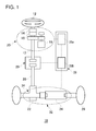
- FIG. 1 schematically shows a structure of a vehicle steering control apparatus according to an embodiment.
- the vehicle steering apparatus 10 includes a steering wheel (handwheel) 12, a steering angle sensor 14, a torque sensor 16, a steering reaction force motor 18, an intermediate shaft 20, a turning angle sensor 22, a turning motor 24, tires 26, a control apparatus 28, and a clutch apparatus 29.
- a steering actuator 30 is constituted by the steering angle sensor 14, the torque sensor 16, and the steering reaction force motor 18.
- a turning actuator 32 is constituted by the turning angle sensor 22 and the turning motor 24.
- the control apparatus 28 controls the steering reaction force motor 18 and the turning motor 24, based on information fed from various sensors included in the steering actuator 30 and the turning actuator 32.
- control apparatus 28 has a steering ECU (electronic control unit) 28a and a turning ECU 28b.
- the steering ECU 28a controls the drive of the steering reaction force motor 18, based on information acquired from the steering angle sensor 14 and the torque sensor 16.
- the turning ECU 28b controls the drive of the turning motor 24, based on information acquired from the turning angle sensor 22 and the like.
- the steering ECU 28a and the turning ECU 28b are configured such that they can communicate with each other when needed.
- the steering wheel 12 is placed on a driver's seat side in a vehicle's passenger compartment, and functions as a steering member rotated in order for a driver to input and effect the steering amount. Also, a main shaft 13, to which an input received from the steering wheel 12 is transmitted, is coupled between the steering wheel 12 and the clutch apparatus 29.
- the steering angle sensor 14 detects a rotation angle of the steering wheel 12, which represents the steering amount inputted by the driver, and then outputs this detected value to the steering ECU 28a.
- the steering angle sensor 14 functions as a detector for detecting the information in response to the steering amount of the steering wheel 12.
- the torque sensor 16 detects a torque corresponding to the steering amount of the steering wheel 12. Based on the control performed by the steering ECU 28a, the steering reaction force motor 18 causes a reaction force to be operated on the steering wheel 12. Here, the reaction force is used to make driver feel and sense a steering reaction force according to the rotation angle of the steering wheel 12 detected by the steering angle sensor 14.
- the steering ECU 28a and the turning ECU 28b are comprised of, for example, CPU, ROM, RAM and data buses connecting them with each other, and follow and run programs stored in ROM.
- the steering ECU 28a and the turning ECU 28b function as the control unit that performs control as follows. That is, the rotation angle of the steering wheel 12, which represents the steering amount inputted by the driver, is first detected. Then a turning amount based on the detected steering amount is calculated, thereby turning the tires 26, by controlling the turning motor 24, based on the calculated turning amount.
- the turning motor 24 constitutes a part of the turning actuator 32, which operates on a rack bar in a vehicle width direction, based on the control performed by the turning ECU 28b.
- the rack bar is coupled to the tire 26 via a tie rod, and extends in the width direction.
- the turning angle sensor 22 detects a rotation angle of a pinon in a rack-and-pinion mechanism 34, which constitutes a part of the turning actuator 32, and then outputs this detected value to the control apparatus 28.
- the intermediate shaft 20 plays a role of transmitting a steering force (rotating force) from the steering actuator 30 to the turning actuator 32, as a part of a backup mechanism in the event that the steer-by-wire system fails to function.
- the backup mechanism is comprised of the intermediate shaft 20, the clutch apparatus 29, the rack-and-pinion mechanism 34, and so forth.
- the clutch apparatus 29 switches the transmission and cutoff of the rotating force between two rotating shafts.
- the vehicle steering apparatus 10 functions as a steer-by-wire system; in this normal mode, the steering actuator 30 and the turning actuator 32 are disconnected and separated by the clutch apparatus 29.
- an abnormality occurs in the system and/or that the output of the turning motor 24 described later is deficient (namely, lower than what is minimally required).
- the steering actuator 30 and the turning actuator 32 are mechanically coupled together by the clutch apparatus 29, so that the tires 26 can be directly turned by an operation of the steering wheel 12.
- the vehicle steering apparatus 10 includes the steering wheel 12, which is rotated to steer the vehicle, the steering actuator 30 that enables a steering-side reaction force to be generated by generating the rotating force transmitted to the steering wheel 12, the steering angle sensor 14 for detecting the information in response to the steering amount of the steering wheel 12, the rack-and-pinion mechanism 34 that functions as the turning mechanism for turning the wheels, the turning actuator 32 that enables the turning-side wheels to be turned by generating the rotating force transmitted to the rack-and-pinion mechanism 34, the clutch apparatus 29, placed between the steering wheel 12 and the rack-and-pinion mechanism 34, which switches the transmission and cutoff of the rotating force between the steering wheel 12 and the rack-and-pinion mechanism 34, and the control apparatus 28.
- the control apparatus 28 While the rotating force between the main shaft 13 and the intermediate shaft 20 is being cut off by the clutch apparatus 29, the control apparatus 28 not only performs control such that a steering-side reaction force is generated by the steering actuator 30 in response to an input to the steering wheel 12 and but also controls the turning position on a turning side by the turning actuator 32, based on the information in response to the steering amount of the steering wheel 12.
- the control apparatus 28 controls the switching such that the clutch apparatus 29 is in a predetermined engagement state, based on information, predicting that the output of the turning actuator 32 required for the controlling of the turning position by the turning actuator 32 will be deficient, or information indicating that the output thereof is actually deficient.
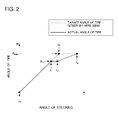
- FIG. 2 schematically shows a relationship between the steering angle and the turning angle.
- the horizontal axis indicates an angle of steering wheel (steering angle), which is an input side
- the vertical axis indicates an angle of tire (turning angle), which is an output side.
- SBW control normal steer-by-wire
- the clutch apparatus 29 works to cut off a rotating force transmitting path between the main shaft 13 and the intermediate shaft 20.
- the steering wheel 12 is rotated starting from a state where the angle r of steering wheel is equal to r 0 , and an angle R of tire increases monotonically until the angle r of steering wheel is equal to r 3 ; when the angle R of tire reaches an end angle R END , the angle R of tire no longer changes even though the steering wheel 12 is rotated further.
- a target angle of tire (dotted line in FIG. 2 ) is not achieved responsive to the change in the angle of steering wheel. If, for example, the friction between the tires and the road surface is high and there exists an obstacle in a moving direction of tires, the output by the turning motor 24 is deficient and therefore lower than that required for the controlling of the target turning position during stationary steering while the vehicle is being stopped, for instance.
- the steering wheel 12 is rotated starting from a state where the angle r of steering wheel is equal to r 0 , and the angle R of tire increases responsive to a change in the angle r of steering wheel until the angle r of steering wheel is equal to r 1 . Since the mechanical coupling between the steering side and the turning side is being disabled by the clutch apparatus 29, the gear ratio of the angle r of steering wheel and the angle R of tire during this time period can be freely selected to a certain degree. During this time period, the tires 26 are turned by the drive power of the turning motor 24.
- the output required for the controlling of the turning position (the angle of tire) by the turning motor 24 is deficient, the actual angle of tire (the solid line in FIG. 2 ) does not change, as shown in FIG. 2 , even though the steering wheel 12 continues to rotate. In other words, the tires are not turned any further than this point.
- the target angle of tire (the dotted line shown in FIG. 2 ) corresponding to the angle of steering wheel deviates from the actual angle of tire and therefore the tires 26 will not be turned to the end angle R END even though the steering wheel 12 is rotated any further.
- control apparatus 28 will switch the states of the clutch apparatus 29 so that the rotating force exerted by an operation of the steering wheel 12 and the rotating force applied to the main shaft 13 by the steering reaction force motor 18 can be transmitted to the turning actuator 32 by way of the intermediate shaft 20 and consequently the rotating force transmitting path can be connected.
- the "information, predicting that the output of the turning motor 24 required for the controlling of the turning position by the turning motor 24 will be deficient" is information indicating, for example, a situation where a stationary steering (which is an action of sharply turning a steering wheel 12 at the time the vehicle is at a stop) is assumed.
- the "information” corresponds to a case where, for example, a state where the vehicle is at a stop or running at an extremely low speed is detected by not-shown vehicle speed sensor and engine speed sensor and then the angle r of steering wheel, which is larger than a predetermined value, is detected by an output of the steering angle sensor 14.
- the "information indicating that the output thereof required for the controlling of the turning position by the turning motor 24 is actually deficient" corresponds to a case where, for example, the angle R of tire detected by the turning angle sensor 22 deviates from the target angle of tire with respect to the angle r of steering wheel detected by the steering angle sensor 14, for instance.
- the control apparatus 28 In order to start an assist control for compensating for a deficiency of the turning force, the control apparatus 28, which has detected such information, switches the states of the clutch apparatus 29 for the purpose of connecting the rotating force transmitting path.
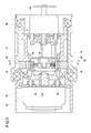
- FIG. 3 is a cross-sectional view of the clutch apparatus 29 in parallel with a shaft of the clutch apparatus 29 according to the present embodiment.
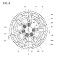
- FIG. 4 is a cross-sectional view of the clutch apparatus 29 taken along the line A-A of FIG. 3 . Note that FIG. 3 corresponds to a cross-sectional view taken along the line B-B' of FIG. 4 .
- the clutch apparatus 29 includes a ring-like steering-wheel-side housing 76, which is a first rotating shaft, a ring-like tire-side housing 78, which is a second rotating shaft, and a plurality of locking bars 80 functioning as engagement portions, which are so provided in the tire-side housing 78 as to be movable in a radial direction of the tire-side housing 78.
- the steering-wheel-side housing 76 is configured such that a plurality of lock grooves 82 are formed in a circumferential direction and also formed mutually at intervals in an inner circumference of the steering-wheel-side housing 76.
- the tire-side housing 78 is provided coaxially with the steering-wheel-side housing 76 and is arranged such that at least part of the tire-side housing 78 overlaps with the steering-wheel-side housing 76 as viewed laterally.
- the steering-wheel-side housing 76 is coupled to the steering actuator 30 (see FIG. 1 ). Thus, the steering-wheel-side housing 76 is rotated in an interlocking manner with the rotation of the steering wheel 12. Also, the tire-side housing 78 is coupled to the turning actuator 32 (see FIG. 1 ) and is rotated interlocked with the rotation of the turning of the tire.
- the clutch apparatus 29 further includes an advancing/retreating mechanism 84 that advances and retreats the locking bars 80 toward and away from the lock grooves 82. The advancing/retreating mechanism 84 will be later described in detail.
- the six locking bars 80 are arranged radially. Each locking bar 80 is slidably supported along an opening 78a formed in a peripheral surface of the ring-like tire-side housing 78.
- a spring support member 86 is fixed near an opening formed in a center of the tire-side housing 78 shown in FIG. 3 .
- the spring support member 86 is configured such that a plurality of protrusions 86b are arranged radially on an outer periphery of a small-diameter part 86a corresponding to each locking bar 80.
- the protrusion 86b supports one end of a spring 90, which is a biasing member, so that the spring 90 will not be displaced or shifted.
- the other end of the spring 90 is also supported by a recess 80a formed in a position corresponding to the spring support member 86 of the locking bar 80. In FIG. 3 and FIG. 4 , the springs 90 are being compressed.
- the advancing/retreating mechanism 84 includes a rotary solenoid 92, which functions as an electrically-driven actuator, springs 90 that biases the locking bars 80 toward the lock grooves 82, pins 94, which control the advancing/retreating of the locking bars 80 by operating on the locking bars 80, a turntable 96 to which the pins 94 are secured.
- the rotary solenoid 92 is configured such that when power is being supplied to the rotary solenoid 92 (i.e., the clutch apparatus being OFF), a shaft 92a rotates in an arrow R3 direction shown in FIG. 4 and such that when no power is supplied thereto (i.e., the clutch apparatus being ON), the shaft 92a rotates in an arrow R4 direction by a biasing force of a returning spring provided inside.
- FIG. 3 and FIG. 4 show a state where power is being supplied to the rotary solenoid 92.
- the pin 94 is engaged with the locking bar 80 in a state where the pin 94 enters or moves into a notched groove 80b, which is formed from a central part of the locking bar 80 toward a lateral surface thereof. Also, the pin 94 abuts against the notched groove 80b with the clutch apparatus being OFF as shown in FIG. 3 , and retreats from the notched groove 80b of the locking bar 80 with the clutch apparatus being ON described later.
- the turntable 96 is secured to the shaft 92a of the rotary solenoid 92 and rotates clockwise or counterclockwise according to an electric conduction state of the rotary solenoid 92. In so doing, the pin 94 rotates clockwise or counterclockwise together with the turntable 96 and changes its position.
- the turntable 96 rotates together with the shaft 92a of the rotary solenoid 92 in the arrow R3 direction, as illustrated in FIG. 4 .
- the pin 94 moves into a back side (deep side) of the notched groove 80b while the pin 94 abuts against a lateral wall 80b1 of the notched groove 80b.
- the locking bar 80 is gradually drawn inside the tire-side housing 78 and finally the locking bar 80 is regulated in a position where the clutch apparatus 29 is in an OFF state.
- the clutch apparatus 29 includes a regulating mechanism 100.
- the regulating mechanism 100 is configured such that when a plurality of locking bars 80 are moved toward the lock grooves 82 by the above-described advancing/retreating mechanism 84, at last one locking bar 80 can be regulated.
- the regulating mechanism 100 includes a pull-type solenoid 102, which functions as an electrically-driven actuator, at least one assist lock pin 104, which controls the advancing/retreating of the locking bars 80 by operating on the locking bars 80, and an adapter 106 to which the assist lock pins 104 are secured.
- the pull-type solenoid 102 is configured such that when no power is supplied thereto (i.e., when the clutch apparatus functions as a bidirectional clutch connection), a shaft 102a is drawn by a biasing force of a returning spring provided inside. And the pull-type solenoid 102 is configured such that during an assist control period described later (i.e., when the clutch apparatus functions as a unidirectional clutch connection), the shaft 102a is protruded by supplying the power thereto.
- FIG. 3 shows a state where no power is supplied to the pull-type solenoid 102 (namely, the pull-type solenoid 102 is turned off).
- FIG. 5 is a cross-sectional view of the clutch apparatus 29 (a clutch being in an ON state or "clutch ON state") in parallel with a shaft of the clutch apparatus 29 according to the present embodiment.
- FIG. 6 is a cross-sectional view of the clutch apparatus 29 taken along the line C-C of FIG. 5 . Note that FIG. 5 corresponds to a cross-sectional view taken along the line D-D' of FIG. 6 .
- the clutch apparatus 29 When no power is supplied due to a system failure or the like, the clutch apparatus 29 operates as follows. That is, the biasing force of a returning spring of the rotary solenoid 92 enables the turntable 96, which has regulated the locking bars 80, to be rotated in an arrow R4 direction shown in FIG. 6 . As a result, the position of the pin 94 inside the notched groove 80b of the locking bar 80 changes and thereby the pin 94 is retreated from the notched groove 80b. As a result, the locking bar 80, whose position has been regulated by the pin 94, can now move toward the lock groove 82 of the steering-wheel-side housing 76.
- the biasing force of the spring 90 causes a radially moving force, which moves in a radial direction of the tire-side housing 78 toward the lock groove 82 of the steering-wheel-side housing 76, to act on each locking bar 80.
- the clutch apparatus 29 is configured such that not all of the locking bars 80 enter the lock groove 82.
- a combination of the locking bars may vary in various manners, depending on the positional relationship between each locking bar 80 (hereinafter referred to as “locking bars 801 to 806" as appropriate, also) and each lock groove 82, namely the positional relationship between the steering-wheel-side housing 76 and the tire-side housing 78.
- the locking bars 801 to 803 enter the lock grooves 82, while the locking bars 804 to 806 abut against protrusions 83 provided between the lock grooves 82, instead of entering the lock grooves 82.
- the state shown in FIG. 6 indicates a case where the clutch apparatus 29 is completely in a clutch ON state. However, the clutch apparatus 29 does not always reach this state upon disconnection of power to the rotary solenoid 92. A detailed description is further given hereinbelow of an operation where the clutch apparatus 29 comes to a complete "clutch-ON" state by a normal operation of the steering wheel 12.
- the steering-wheel-side housing 76 is in a position rotated slightly in the arrow R4 direction from the state of FIG. 6 (while the tire-side housing 78 remains in the state of FIG. 6 ).
- the locking bars 802 and 803 enter the lock grooves 82 but the locking bars 801, 804 to 806 abut against the protrusions 83 on an inner peripheral wall of the steering-wheel-side housing 76.
- the locking bars 802 and 803, which have entered the lock grooves 82 both do not abut against lateral surfaces 82a and 82b.
- backlashes are created, in a rotation direction, between the steering-wheel-side housing 76 and the tire-side housing 78.
- the locking bar 801 enters the lock groove 82 and is engaged with the other lateral surface 82b of the lock groove 82 when the locking bar 803 abuts against one lateral surface 82a of the lock groove 82 and is engaged with it.
- the backlashes, in the rotation direction, between the steering-wheel-side housing 76 and the tire-side housing 78 are almost no longer existent (in a locked state) by the locking bar 801, which enters a lock groove 821 and is engaged with the other lateral surface 82b, and the locking bar 803, which enters a lock groove 823 and is engaged with one lateral surface 82a.
- the rotating force of the steering-wheel-side housing 76 can be reliably transmitted to the tire-side housing 78.
- the plurality of locking bars 80 have a first locking bar (the locking bar 803 in FIG. 6 ) and a second locking bar (the locking bar 801 in FIG. 6 ). More specifically, when the locking bars 80 move toward the plurality of lock grooves 82 by the advancing/retreating mechanism 84 including the rotary solenoid 92, the first locking bar 803 enters any one of the lock grooves (the lock groove 823 in FIG. 6 ), which is referred to as a "first lock groove" also, regardless of difference in rotational phase between the steering-wheel-side housing 76 and the tire-side housing 78.
- the second locking bar 801 enters a second lock groove (the lock groove 821 in FIG. 6 ), which differs from the first lock groove.
- the locking bar 801 enters the lock groove 821, the locking bar 801 is engaged with the lateral surface 82b, which is one of two lateral surfaces 82a and 82b of the lock groove 821, on the other rotation direction (the arrow R3 direction) side.
- the clutch apparatus 29 retreats each locking bar 80 from the lock groove 82 by the advancing/retreating mechanism 84, so that the vehicle steering apparatus 10 can be set to a separate state (disconnected state) where the rotating force is not transmitted in between the steering-wheel-side housing 76 and the tire-side housing 78.
- the steering-wheel-side housing 76 is rotated in one rotation direction (e.g., in the arrow R3 direction) in a state (a locked state) where the steering-wheel-side housing 76 and the tire-side housing 78 are connected to each other by the advancing/retreating mechanism 84, the locking bar 803 is engaged with the lateral surface 82a, which is one of two lateral surfaces of the lock groove 823, on the other rotation direction (the arrow R4 direction) side.
- the rotating force can be transmitted to the tire-side housing 78 with almost no backlash.
- the locking bar 801 is engaged with the lateral surface 82b, which is one of two lateral surfaces of the lock groove 821, on one rotation direction (the arrow R3 direction) side.
- the rotating force can be transmitted to the tire-side housing 78 with almost no backlash.
- the clutch apparatus 29 is configured such that the locking bar 80 is retreated from the lock groove 82 by a force, which is larger than a biasing force of the spring 90 and which results from a movement caused when power is supplied to the rotary solenoid 92, and such that when no power is supplied to the rotary solenoid 92, the locking bar 802 and the locking bar 803 enter the lock grooves 82 by the biasing force of the springs 90.
- the locking bar 802 and the locking bar 803 enter the lock grooves 82, so that the steering-wheel-side housing 76 and the tire-side housing 78 can be promptly connected together.
- the clutch apparatus 29 advances and retreats the locking bars 80 by converting the rotary motion of the rotary solenoid 92.
- the length of the clutch apparatus in a shaft direction can be suppressed.
- FIG. 7 is a diagram for explain the shapes of the locking bar 80 and the lock groove 82.
- FIG. 8 is a schematic diagram linearly showing a relationship, between the locking bars and the lock grooves, shown in FIG. 7 .
- the number of lock grooves 82 (the plurality n of the lock grooves 82) is denoted by n [pieces]
- the pitch of the lock grooves 82 is denoted by P
- each parameter in the clutch apparatus 29 is so set to satisfy the following Equations (1) to (3).
- At least one locking bar 80 is always in a position where it can enter a lock groove 82, regardless of a relative phase between the steering-wheel-side housing 76 and the tire-side housing 78. Also, the design can be made such that the shifted angle ⁇ , which may be formed when the steering-wheel-side housing 76 and the tire-side housing 78 are connected (a locked state), is taken into consideration.
- the shifted angle ⁇ formed at the time of connection is a parameter indicating an angle at which the clutch ON state (locked state) is achieved in the clutch apparatus 29 when one of the steering-wheel-side housing 76 and the tire-side housing 78 is rotated relative to the other thereof, by the shifted angle ⁇ formed at the time of connection, regardless of a relative phase between the steering-wheel-side housing 76 and the tire-side housing 78.
- setting the shifted angle ⁇ smaller allows the steering actuator 30 and the turning actuator 32 to be mechanically coupled together with a slight amount of operation (movement) of the steering wheel in the event of occurrence of an abnormality in the system. This helps to improve the responsiveness in a fail-safe mechanism in the vehicle steering apparatus 10.
- the vehicle steering apparatus 10 includes the steering wheel 12, which is rotated to steer the vehicle, the steering angle sensor 14 for detecting the information in response to the steering amount of the steering wheel 12, the rack-and-pinion mechanism 34 for turning the tires 26, the turning motor 24 for driving the rack-and-pinion mechanism 34, the clutch apparatus 29, placed between the steering wheel 12 and the rack-and-pinion mechanism 34, which switches the transmission and cutoff of the rotating force between the steering wheel 12 and the rack-and-pinion mechanism 34, and the control apparatus 28, which drives the turning motor 24 and controls the turning amount based on the information in response to the steering amount, in a state where the rotating force has been cut off by the clutch apparatus 29.
- the steering wheel 12 is coupled to the steering-wheel-side housing 76.
- the rack-and-pinion mechanism 34 is coupled to the tire-side housing 78.
- the steering-wheel-side housing 76 and the tire-side housing 78 are mechanically coupled to each other such that the turning angel of the wheels can change in response to an operation of the steering wheel, while the rotating force between the steering wheel 12 and the rack-and-pinion mechanism 34 is transmittable.
- the turning motor 24 is driven. And when the turning amount is controlled based on the information in response to the steering amount of the steering wheel 12, the torque variation and the like are not transmitted to the steering wheel 12 from the rack-and-pinion mechanism 34. This can improve the steering feeling.
- the control apparatus 28 switches the state to a connection state where an assist control can be performed on the clutch apparatus 29, within a range (r 1 ⁇ r ⁇ r 2 ) where the angle of tire remains unchanged against the change of the angle r of steering wheel.
- FIG. 9 is a cross-sectional view of the clutch apparatus 29 (pre-assist-control state) in parallel with a shaft of the clutch apparatus 29 according to the present embodiment.
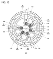
- FIG. 10 is a cross-sectional view of the clutch apparatus 29 taken along the line E-E of FIG. 9 . Note that FIG. 9 corresponds to a cross-sectional view taken along the line F-F' of FIG. 10 .
- the regulating mechanism 100 includes five assist lock pins 104, which are engaged with five locking bars 802 to 806 excluding the locking bar 801.
- the positions of the five locking bars 802 to 806 excluding the locking bar 801 are regulated at their positions indicated in FIG. 10 .
- the locking bar 801 is retreated from the lock groove 82 by the advancing/retreating mechanism 84, the position of the locking bar 801 will not be regulated by the regulating mechanism 100.
- FIG. 11 is a cross-sectional view of the clutch apparatus 29 (assist-control state) in parallel with a shaft of the clutch apparatus 29 according to the present embodiment.
- FIG. 12 is a cross-sectional view of the clutch apparatus 29 taken along the line G-G of FIG 11 . Note that FIG. 11 corresponds to a cross-sectional view taken along the line H-H' of FIG. 12 .
- the control apparatus 28 turns off the rotary solenoid 92 of the advancing/retreating mechanism 84 in the state shown in FIG. 10 .
- the turntable 96 which has regulated the locking bars 80, are rotated in an arrow R4 direction indicated in FIG. 12 by the biasing force of the returning spring of the rotary solenoid 92.
- the position of the pin 94 inside the notched groove 80b of each of the locking bars 801 to 806 changes and thereby the pin 94 is retreated from the notched groove 80b.
- the assist lock pins 104 are engaged into the assist lock grooves 108 in the locking bars 802 to 806, respectively; thus the positions of the locking bars 802 to 806 are regulated so that the locking bars 802 to 806 cannot move toward the lock grooves 82 of the steering-wheel-side housing 76.
- the assist lock pin 104 is not engaged into the assist lock groove 108 in the locking bar 801 and therefore the locking bar 801 can move toward the lock groove 82 of the steering-wheel-side housing 76.
- the biasing force of the spring 90 causes a radially moving force, which moves in a radial direction of the tire-side housing 78 toward the lock groove 82 of the steering-wheel-side housing 76, to exert on the locking bar 801.
- the clutch apparatus 29 can be instantly switched to the unidirectional clutch connection state, when the output of the turning motor 24 is deficient.
- the locking bar 801 enters the lock groove 82.
- the steering wheel 12 is further rotated and thereby the steering-wheel-side housing 76 is rotated in an arrow R5 direction, the locking bar 801 abuts against the other lateral surface 82b of the lock groove 82 and is engaged therewith (the angle r of steering wheel being equal to r 2 : see FIG. 2 ).
- the width W [deg] of the locking bar 801 is smaller than the width B1 [deg] of the lock groove 82.
- the clutch apparatus 29 is configured such that a predetermined amount of relative rotation ⁇ , which is equal to (B1-W), between the steering-wheel-side housing 76 and the tire-side housing 78, is permitted in a state where locking bars 80 can be engaged into the lock grooves 82.
- the locking bar 80 is of such a shape that the rotation in at least one direction is permitted in the tire-side housing 78 while the locking bar 80 has entered the lock groove 82.
- the relative rotation ⁇ is designed such that the value thereof is larger than a relative rotation (backlash) permitted during the clutch connection ON state shown in FIG. 6 .
- the steering ECU 28a controls the steering reaction force motor 18 such that the steering reaction force motor 18 applies the rotation force, whose rotation direction is the same as that of the steering wheel 12, to the main shaft 13.
- the assist control is performed in the range of r 2 to r 4 for the angle r of steering wheel (in the range of R 1 to REND for the angle R of tire).
- the steering reaction force motor 18 can supplement the output, in a predicted situation where the output of the turning motor 24 required for the controlling of the turning position by the turning motor 24 will be deficient, in a situation where the output thereof is actually deficient, and in the like situation.
- the angle of tire may possibly vary abruptly. More specifically, in this case, the turning-side rotating shaft may possibly turn sharply and simultaneously the steering-side rotating shaft, which has been connected to the turning-side rotating shaft, may possibly be affected and rotated, too. In particular, if the turning-side rotating shaft and the steering-side rotating shaft are connected in a completely locked state via the clutch apparatus, the rotation of the turning-side rotating shaft will be transmitted to the steering wheel through the steering-side rotating shaft. This may possibly bring about the so-called self-steer state where the steering wheel is rotated against the driver's intention.
- the rotating force transmitting path between the main shaft 13 and the intermediate shaft 20 are being connected by using the clutch apparatus 29, a predetermined amount of relative rotation in between the main shaft 13 (the steering-wheel-side housing 76) and the intermediate shaft 20 (the tire-side housing 78) is permitted as shown in FIG. 12 .
- the tire-side housing 78 shown in FIG. 12 rotates relative to the steering-wheel-side housing 76 in an arrow R6 direction, the locking bar 80 will get separated away from the lateral surface of the lock groove 82, so that the steering-wheel-side housing 76 can be spaced away from the tire-side housing 78.
- the engagement state of the steering-wheel-side housing 76 and the tire-side housing 78 is released with the result that the rotation fore is no longer transmitted therebetween.
- the clutch apparatus 29 achieves a first engagement state (a bidirectional clutch connection state shown in FIG. 6 ) and a second engagement state (a unidirectional clutch connection state).
- first engagement state the two rotating shafts, which are the steering-wheel-side housing 76 and the tire-side housing 78, are locked with each other, with a backlash, which is less than or equal to a first predetermined amount, so that the rotation force can be transmitted for the rotation in both directions.
- a relative rotation ⁇ having a second predetermined amount, which is greater than the first predetermined amount is allowed between the two rotating shafts.
- locking the two shafts with each other transmits the rotating force for the rotation in both directions, in the event that an abnormality occurs in the system where the clutch apparatus 29 is used (e.g., when a failure occurs in the steering apparatus and/or a vehicle's power supply).
- an abnormality occurs in the system where the clutch apparatus 29 is used (e.g., when a failure occurs in the steering apparatus and/or a vehicle's power supply).
- the rotation of one rotating shaft (the tire-side housing 78) is to be assisted by using the rotating force acting on the other rotating shaft (the steering-wheel-side housing 76) even though the system used in the clutch apparatus operates normally.
- permitting the relative rotation ⁇ having the second predetermined amount larger than the first predetermined amount enables the rotating force to be not only transmitted by using the rotation in one direction and but also cut off when rotated in the other direction.
- the use of the above-described clutch apparatus 29 for the vehicle steering apparatus 10 allows the two rotating shafts to be rotated relatively to each other in a situation where, for example, the assist control for the rotation is no longer required. As a result, the transmission of the rotating force is quickly cut off and therefore the steering feeling can be improved.
- the first predetermined amount may be set in consideration of the component tolerances and the precision required for the mechanical connection of components, for instance. Or the first predetermined amount may be set in consideration of a backlash permitted in terms of the operability of a system (e.g., a steering apparatus) where a clutch apparatus is used, and so forth.
- the first predetermined amount in the present embodiment may be thought of as a backlash in the steering wheel operation during a bidirectional (complete) clutch connection state shown in FIG. 6 .
- the second predetermined amount according to the present embodiment which is a value larger than the first predetermined amount, may be an approximately set value, by which a first state of the two rotating shafts being connected and a second state thereof being not connected can be clearly distinguished between the first and second states.
- the second predetermined amount is not a value having the magnitude of a backlash or looseness between the components but may be suitably expressed as a value set for the purpose of realizing an intended operation (the aforementioned unidirectional clutch connection).
- the clutch apparatus 29 may be also defined and summarized in a generic manner as follows.
- the clutch apparatus 29 is a clutch apparatus for switching the transmission and cutoff of the rotating force between the steering-wheel-side housing 76 and the tire-side housing 78, and is configured such that a first mode, a second mode and a third mode are switchable therebetween.
- the first mode is a mode (a clutch connection OFF state) in which the rotating force is not transmitted between the steering-wheel-side housing 76 and the tire-side housing 78.
- the second mode is a mode (the bidirectional clutch connection state) in which the rotation force is transmittable for the rotation in both directions while the steering-wheel-side housing 76 and the tire-side housing 78 are locked with each other.
- the third mode is a mode (the unidirectional clutch connection state) in which the transmission of the rotating force is cancelable such that while the rotating force is transmittable, between the steering-wheel-side housing 76 and the tire-side housing 78, for the rotation in one direction, the rotation of either the steering-wheel-side housing 76 or the tire-side housing 78 in the other direction is permitted.
- the third mode can be achieved where the transmission of the rotating force is cancelable such that while the rotating force is transmittable, between the steering-wheel-side housing 76 and the tire-side housing 78, for the rotation in one direction, the rotation of either the steering-wheel-side housing 76 or the tire-side housing 78 in the other direction is permitted (the unidirectional clutch connection state).
- the unidirectional clutch connection state the unidirectional clutch connection state
- the rotation of the tire-side housing 78 is to be assisted by using the rotating force acting on the steering-wheel-side housing 76 even though the system used in the clutch apparatus 29 operates normally. Then, in this case, permitting the relative rotation ⁇ , having an amount greater than or equal to a certain reference amount, enables the rotating force to be not only transmitted by using the rotation in one direction and but also cut off when rotated in the other direction.
- the use of the above-described clutch apparatus 29 for the vehicle steering apparatus 10 allows the two rotating shafts to be rotated relatively to each other in a situation where, for example, the assist control for the rotation is no longer required. As a result, the transmission of the rotating force is quickly cut off and therefore the steering feeling can be improved.
- a plurality of locking bars 80 include: a locking bar 803, which enters a lock groove 823 (see FIG. 6 ) as a first groove, which is any one of the plurality of lock grooves 82, regardless of a difference in rotational phases between the steering-wheel-side housing 76 and the tire-side housing 78, when the advancing/retreating mechanism 84 moves a plurality of locking bars 80 toward the lock grooves 82; and a locking bar 801, which enters a lock groove 821, which differs from the lock groove 823, when the locking bar 803 moves in either a clockwise or counterclockwise direction, with the locking bar 803 having entered the lock groove 823.
- the locking bar 803 is configured such that, while the locking bar 803 and the locking bar 801 have entered their corresponding lock grooves 823 and 821, a backlash between the locking bar 803 and a lateral surface (a lateral surface 82a shown in FIG. 6 ), which is one of two lateral surfaces of the lock groove 823, on one rotation direction side near the locking bar 801, is less than or equal to the first predetermined amount.
- a separate state (disconnected state), where the rotating force is not transmitted in between the steering-wheel-side housing 76 and the tire-side housing 78, can be set by retreating the locking bars 80 from the lock grooves 82 by using the advancing/retreating mechanism 84.
- the steering-wheel-side housing 76 is rotated in one rotation direction (the arrow R3 direction shown in FIG. 6 ) in a state where the steering-wheel-side housing 76 and the tire-side housing 78 are clutch-connected to each other by the advancing/retreating mechanism 84, the locking bar 803 is engaged with a lateral surface (a lateral surface 82a shown in FIG.
- a plurality of locking bars 80 include: a first locking bar (803) that enters a first lock groove (a lock groove 823 shown in FIG. 6 ), which is any one of a plurality of lock grooves regardless of a difference in rotational phases between the steering-wheel-side housing 76 and the tire-side housing 78, when the advancing/retreating mechanism 84 moves a plurality of locking bars 80 toward lock grooves 82; and a second locking bar (the locking bar 801 shown in FIG. 6 ), which enters the second lock groove (the lock groove 821 shown in FIG.
- the locking bar 801 is configured such that when the locking bar 801 enters the lock groove 821, the locking bar 801 is engaged, with the backlash, which is less than or equal to the first predetermined amount, onto a lateral surface, which is one of two lateral surfaces of the lock groove 821, on the other rotation direction side.
- a separate state disconnected state
- the rotating force is not transmitted in between the steering-wheel-side housing 76 and the tire-side housing 78, can be set by retreating the locking bars from the lock grooves by using the advancing/retreating mechanism 84.
- the steering-wheel-side housing 76 and the tire-side housing 78 can be rotated relatively to each other in a situation where, for example, the assist of the rotating force to the rack-and-pinion mechanism 34 is no longer required. This allows the transmission of the rotating force to be quickly cut off, so that the steering feeling can be improved.
- the vehicle steering apparatus 10 further includes the turning angle sensor 22, which detects information in response to the turning amount of the rack-and-pinion mechanism 34.
- the control apparatus 28 switches the clutch connection state to the unidirectional clutch connection state, based on at least one of the information (the angle of steering wheel) in response to the steering amount acquired from the steering angle sensor 14 and the information (the angle of tire) in response to the turning amount acquired from the turning angle sensor 22.
- the assist control to the rack-and-pinion mechanism 34 using the steering actuator 30 and an operation of the steering wheel 12 can be quickly achieved or achieved by predicting it beforehand.
- the steering reaction force motor 18 is controlled by the steering ECU 28a, and the turning motor 24 is controlled by the turning ECU 28b.
- the two motors are driven by the separate ECUs as with this case, it is difficult to control the two motors in a coordinated manner because of the limited operation speeds and the limited communication rate between the ECUs.
- the rotating force produced by the steering reaction force motor 18 via the clutch apparatus 29 is transmitted to the turning actuator 32 only when the output by the turning motor 24 is deficient. In other words, the deficiency in the output by the turning motor 24 is always fed back to the steering ECU 28a, which controls the steering reaction force motor 18.
- the control interference between the two ECUs can be prevented as compared with the case where the steering reaction force motor 18 and the turning motor 24 are separately controlled by the two ECUs for the purpose of obtaining a desired turning force required for the controlling of the turning position.
- the clutch apparatus is configured such that at least one locking bar enters a lock groove when the power to the actuators is disconnected. Then, the clutch apparatus is configured such that at least one locking bar is definitely engaged into a lock groove by a rotating operation at the shifted angle ⁇ , which is caused at the time of the connection, or below and such that another locking bar enters another lock groove. Then the two locking bars hold the lateral surfaces of the two different lock grooves, in between these locking bars, so that a locked state with almost no backlash can be achieved.
- the clutch apparatus will not be in a separate state under a high torque as in a friction clutch.
- a plurality of locking bars can be moved in linkage with the movement of a single actuator, so that the locking bars can be easily synchronized with each other.
- the clutch apparatus when the clutch is released (clutch OFF), the positions of all the locking bars are constrained, so that the locking bars can be stably secured.
- the positional restriction of the locking bars is lifted. Thereby, the locking bars are separately moved by the springs.
- the locking bars, which enter lock grooves, and the those not entering any of the lock grooves are separately moved.
- the rotary solenoid 92 is used as the advancing/retreating mechanism 84
- the pull-type solenoid 102 is used as the regulating mechanism 100.
- both the advancing/retreating mechanism 84 and the regulating mechanism 100 use the rotary solenoids or the pull-type solenoids, the structure may possibly be complex or the overall size of the apparatus may possibly be increased because three connection states are achieved by a single clutch apparatus.
- the steering reaction force motor 18 used for the SBW control can also be used, for the assist control, through the operation of the clutch apparatus 29.
- the clutch apparatus in which the lock grooves are formed in an inner circumference of the steering-wheel-side housing and the locking bars are provided in the tire-side housing.
- the clutch apparatus may be configured such that the locking bars are provided in the steering-wheel-side housing and such that the lock grooves are formed in an outer circumference of the tire-side housing.
- a plurality of assist lock pins 104 are driven by a single pull-type solenoid 102. Instead, a plurality of assist lock pins 104 may be separately driven by using two or more actuators. Then, the regulating mechanism 100 may select an assist lock pin or assist lock pins 104, which can quickly achieve the unidirectional clutch connection, based on the information on the angles of rotation of the steering-wheel-side housing 76 and the tire-side housing 78, and thereby may regulate the movement of some of the locking bars 80.
- the number of assist lock pins 104 is less than that of locking bars 80 by one, the numbers thereof and the arrangements are not limited thereto and various other modifications are possible within a range in which the unidirectional clutch connection state can be achieved.
- any combination of locking bars may be suitable as long as the clutch apparatus is not in the bidirectional clutch connection state with the applicable locking bar having entered a lock groove.
- the number of assist lock pins 104 in the regulating mechanism 100 and the arrangement thereof may preferably be set as follows. That is, the number thereof and the arrangement thereof may be set such that when control, for which the unidirectional clutch connection is required, is to be performed, the combination of locking bars entering a lock groove is neither the combination of the locking bar 801 and the locking bar 803, the combination of the locking bar 802 and the locking bar 805, the combination of the locking bar 803 and the locking bar 805, nor the combination of the locking bar 804 and the locking bar 806.
- the same locking bar 80 or the same locking bars 80 is/are used for both the unidirectional clutch connection state and the bidirectional clutch connection state.
- a locking bar driven during the unidirectional clutch connection state assist control
- a locking bar driven during the bidirectional clutch connection state bidirectional clutch connection state
- the actuators used for the respective controls may be provided separately.
- the present invention can be used for a steering apparatus for a vehicle.
Landscapes
- Engineering & Computer Science (AREA)
- General Engineering & Computer Science (AREA)
- Mechanical Engineering (AREA)
- Physics & Mathematics (AREA)
- Electromagnetism (AREA)
- Chemical & Material Sciences (AREA)
- Combustion & Propulsion (AREA)
- Transportation (AREA)
- Fluid Mechanics (AREA)
- Power Steering Mechanism (AREA)
- Mechanical Operated Clutches (AREA)
Abstract
Description
- The present invention relates to a clutch apparatus and it particularly relates to a clutch apparatus used for a vehicle steering apparatus.
- In recent years, a system for the steering of an automobile, which is so-called a "steer-by-wire system", has been developed for practical use in variety of manners. Where the steer-by-wire system is used, it is generally practiced that either one of the following mechanisms is prepared in advance in order to secure the steering capability just in case a failure or defect occurs in the system. That is, prepared are either a coupling mechanism for mechanically coupling a steering wheel (handwheel) with turning wheels, separately from the steer-by-wire system, or its equivalent mechanism, which is so-called a fail-safe mechanism.
- Also, the steer-by-wire system detects an input entered by a vehicle's driver, such as a torque and a steering angle, by sensors. And the steer-by-wire system combines this detected input with the information acquired from other sensors provided in the vehicle, and thereby derives a steering angle suitable for the running condition of the vehicle. Then the steer-by-wire system sends this steering command value to a steering actuator so as to actually steer the wheels (i.e., the turning wheels). The output of a motor used as an actuator for turning the wheels is determined on the assumption of a steering wheel operation (during stationary steering) at the time when the force required for the turning of the wheels is the maximum while the vehicle is being stopped. For this reason, a high-output and large-sized motor is required then.
- In the light of this, a vehicle steering apparatus is proposed (see Patent Document 1 listed in the following Related Art Documents) in order that a small-sized, low-priced and low-output motor can be used. That is, in this vehicle steering apparatus, a clutch mechanism is coupled during stationary steering and thereby a steering mechanism and a turning mechanism are mechanically coupled together. And the drive of a turning power motor and a reaction-force motor is controlled so as to turn the wheels. By employing this vehicle steering apparatus, it seems that the output of the turning power motor during stationary steering can be suppressed and the size of the turning power motor can be made small.
- [Patent Document 1] Japanese Patent Application Publication No.
2008-195187 - In the above-described vehicle steering apparatus, however, during stationary steering, the clutch mechanism is coupled and the output of the turning power motor is assisted by driving the reaction-force motor. Accordingly, when a necessary turning force in this state drops abruptly, a large turning force, which has been applied to turn the tires so far, is shifted to a steering shaft side. This may possibly bring about a so-called self-steer state where the steering shaft is moved more than necessary. For this reason, there is still room for improvement in the feeling sensed by the driver when a steering operation is done.
- The present invention has been made in view of the foregoing circumstances, and a purpose thereof is to provide a technology capable of improving the steering feeling in a steering apparatus.
- In order to resolve the above-described problems, a clutch apparatus according to one embodiment of the present invention switches transmission and cutoff of a rotating force between two rotating shafts, and the clutch apparatus includes: a first rotating shaft formed circumferentially such that a plurality of grooves are formed mutually at intervals in an inner or outer circumference; a second rotating shaft arranged such that the second rotating shaft is placed coaxially with the first rotating shaft and such that at least part of the second rotating shaft overlaps with the first rotating shaft; a plurality of engagement portions arranged in a circumferential direction of the second rotating shaft such that the plurality of engagement portions are placed mutually at intervals, the engagement portions being so provided in the second rotating shaft as to be movable in a radial direction of the second rotating shaft; an advancing/retreating mechanism that advances and retreats the engagement portions toward and away from the grooves; and a regulating mechanism that regulates movement of at least one of the engagement portions, when the advancing/retreating mechanism moves the plurality of engagement portions toward the grooves. The plurality of engagement portions and the plurality of grooves are so configured as to achieve a first engagement state and a second engagement state, the first engagement state being a state of the engagement portions and the grooves where the two rotating shafts are locked with each other, with a backlash, which is less than or equal to a first predetermined amount, such that a predetermined combination of two engagement portions enter their corresponding grooves in the plurality of grooves by the advancing/retreating mechanism, whereby the rotating force is transmittable for a rotation in both directions, and the second engagement state being a state thereof where a relative rotation having a second predetermined amount, which is greater than the first predetermined amount, is allowed between the two rotating shafts such that the advancing/retreating mechanism restricts a movement of one of the predetermined combination of two engagement portions into the groove.
- By employing this embodiment, the two rotating shafts are locked with each other with the backlash, which is less than or equal to the first predetermined amount. And this embodiment can realize the first engagement state, where the rotating force is transmittable to the rotation in both directions, and the second engagement state, where the relative rotation having the second predetermined amount, which is greater than the first predetermined mount, is permitted between the two rotating shafts. Thus, locking the two shafts with each other transmits the rotating force for the rotation in both directions, in the event that, for example, an abnormality occurs in the system where the clutch apparatus is used. Also, suppose that the rotation of one rotating shaft is to be assisted by using the rotating force acting on the other rotating shaft even though the system used in the clutch apparatus operates normally. Then, in this case, permitting the relative rotation having the second predetermined amount larger than the first predetermined amount enables the rotating force to be not only transmitted by using the rotation in one direction and but also cut off when rotated in the other direction. In this manner, the use of the above-described clutch apparatus for a vehicle steering apparatus allows the two rotating shafts to be rotated relatively to each other in a situation where, for example, the assist control for the rotation is no longer required. As a result, the transmission of the rotating force is quickly cut off and therefore the steering feeling can be improved.
- Here, the first predetermined amount may be set in consideration of the component tolerances and the precision required for the mechanical connection of components, for instance. Or the first predetermined amount may be set in consideration of a backlash permitted in terms of the operability of a system (e.g., a steering apparatus) where a clutch apparatus is used, and so forth. Also, the second predetermined amount, which is a value larger than the first predetermined amount, may be an approximately set value, by which a first state of the two rotating shafts being connected and a second state thereof being not connected can be clearly distinguished between the first and second states. In other words, the second predetermined amount is not a value having the magnitude of a backlash or looseness between the components but may be suitably expressed as a value set for the purpose of realizing an intended operation (e.g., a unidirectional clutch connection).
- The plurality of engagement portions may include: a first engagement portion that enters a first groove, which is any one of the plurality of grooves, regardless of a difference in rotational phases between the first rotating shaft and the second rotating shaft, when the advancing/retreating mechanism moves the plurality of engagement portions toward the plurality of grooves; and a second engagement portion that enters a second groove, which differs from the first groove, when the first engagement portion moves in either a clockwise or counterclockwise direction with the first engagement portion having entered the first groove. The first engagement portion may be configured such that, while the first engagement portion and the second engagement portion have entered their corresponding grooves, a backlash between the first engagement portion and a lateral surface, which is one of two lateral surfaces of the first groove, on one rotation direction side near the first engagement portion, is less than or equal to the first predetermined amount. By employing this embodiment, a separate state (disconnected state), where the rotating force is not transmitted in between the first rotating shaft and the second rotating shaft, can be set by retreating the engagement portions from the grooves by using the advancing/retreating mechanism. On the other hand, when the first rotating shaft is rotated in one rotation direction in a state where the rotating shaft and the second rotating shaft are connected to each other by the advancing/retreating mechanism, the first engagement portion is engaged with a lateral surface, which is one of two lateral surfaces of the first groove, on the other rotation direction side. Thus, the rotating force can be quickly transmitted to the second rotating shaft with almost no backlash. Also, when the first rotating shaft is rotated in the other rotation direction, the second engagement portion is engaged with a lateral surface, which is one of two lateral surfaces of the second groove, on one rotation direction side. Thus, the rotating force can be quickly transmitted to the second rotating shaft with almost no backlash.
- The plurality of engagement portions may include: a first engagement portion that enters a first groove, which is any one of the plurality of grooves regardless of a difference in rotational phases between the first rotating shaft and the second rotating shaft, when the advancing/retreating mechanism moves the plurality of engagement portions toward the grooves; and a second engagement portion that enters a second groove, which differs from the first groove, when the first engagement portion moves in either a clockwise or counterclockwise direction, with the first engagement portion having entered the first groove, and is engaged with a lateral surface, which is one of two lateral surfaces of the first groove, on one rotation direction side. The second engagement portion may be configured such that when the second engagement portion enters the second groove, the second engagement is engaged, with the backlash, which is less than or equal to the first predetermined amount, onto a lateral surface, which is one of two lateral surfaces of the second groove, on the other rotation direction side. By employing this embodiment, a separate state (disconnected state), where the rotating force is not transmitted in between the first rotating shaft and the second rotating shaft, can be set by retreating the engagement portions from the grooves by using the advancing/retreating mechanism. On the other hand, when the first rotating shaft is rotated in one rotation direction in a state where the first rotating shaft and the second rotating shaft are connected to each other by the advancing/retreating mechanism, the first engagement portion is engaged with a lateral surface, which is one of two lateral surfaces of the first groove, on the other rotation direction side. Thus, the rotating force can be quickly transmitted to the second rotating shaft with almost no backlash. Also, when the first rotating shaft is rotated in the other rotation direction, the second engagement portion is engaged with a lateral surface, which is one of two lateral surfaces of the second groove, on one rotation direction side. Thus, the rotating force can be quickly transmitted to the second rotating shaft with almost no backlash.
- The advancing/retreating mechanism may include: an actuator driven by electricity; and a biasing member that biases the engagement portion toward the groove. An operation of the actuator, which is turned on, may cause the engagement portion to be retreated from the groove by a force, which is larger than the biasing force of the biasing member; and when the actuator is turned off, the first engagement portion may enter the first groove by the biasing force of the biasing member. Thereby, at a time of emergency when the power to the actuator is disconnected, the first engagement portion enters the first groove, so that the first shaft and the second shaft can be connected together promptly.
- The actuator may be a rotary solenoid, and the advancing/retreating mechanism may further include a conversion mechanism for converting a rotary motion of the rotary solenoid so as to advance and retreat the engagement portion. Thereby, the length of the clutch apparatus in a shaft direction can be suppressed.
- The engagement portions and the grooves may be so provided to satisfy P = 360/n, B1 ≈ W+(δ×(Nx-1)), and δ = P/N, where n indicates the number of grooves (the plurality n of the grooves), P indicates a pitch of the grooves, N indicates the number of engagement portions (the plurality N of the engagement portions), Nx indicates the number of engagement portions entering a plurality of the grooves, W indicates width of the engagement portion, B1 indicates width of the groove, B2 indicates a distance between the groove and a groove adjacent thereto, and δ indicates a shifted angle formed when the engagement portion is engaged into the groove. Thereby, a design can be implemented where, for example, the shifted or deviated angle, which may occur at the time of the connection, has been taken into consideration.
- Another embodiment of the present invention relates also to a clutch apparatus. The apparatus is a clutch apparatus for switching transmission and cutoff of a rotating force between a first rotating shaft and a second rotating shaft, and a first mode, a second mode and a third mode are switchable therebetween, where the first mode is a mode in which the rotating force is not transmitted between the first rotating shaft and the second rotating shaft, the second mode is a mode in which the rotation force is transmittable for a rotation in both directions while the first rotating shaft and the second rotating shaft are locked with each other, and the third mode is a mode in which a transmission of the rotating force is cancelable such that while the rotating force is transmittable, between the first rotating shaft and the second rotating shaft, for a rotation in one direction, the rotation of either the first rotating shaft or the second rotating shaft in the other direction is allowed.
- In addition to the operation of the clutch apparatus that transmits and cuts off the rotation force, this embodiment can achieve the third mode in which the transmission of the rotating force is cancelable such that while the rotating force is transmittable, between the first rotating shaft and the second rotating shaft, for the rotation in one direction, the rotation of either the first rotating shaft or the second rotating shaft in the other direction is permitted. Thus, locking the two shafts with each other transmits the rotating force for the rotation in both directions, in the event that, for example, an abnormality occurs in the system where the clutch apparatus is used. Also, suppose that the rotation of one rotating shaft is to be assisted by using the rotating force acting on the other rotating shaft even though the system used in the clutch apparatus operates normally. Then, in this case, permitting the relative rotation, having an amount greater than or equal to a certain reference amount, enables the rotating force to be not only transmitted by using the rotation in one direction and but also cut off when rotated in the other direction. Thus, the use of the above-described clutch apparatus for a vehicle steering apparatus allows the two rotating shafts to be rotated relatively to each other in a situation where, for example, the assist control for the rotation is no longer required. As a result, the transmission of the rotating force is quickly cut off and therefore the steering feeling can be improved.
- Still another embodiment of the present invention relates to a steering apparatus. The apparatus includes: an operating member rotated to steer a vehicle; a steering actuator that enables a steering-side reaction force to be generated by generating a rotating force transmitted to the operating member; a steering amount detector that detects information in response to a steering amount of the operating member; a turning mechanism that turns wheels, a turning actuator that enables the turning-side wheels to be turned by generating a rotating force transmitted to the turning mechanism, the above-described clutch apparatus, placed between the operating member and the turning mechanism, which switches transmission and cutoff of the rotating force between the operating member and the turning mechanism; and a control apparatus that not only performs control such that the steering-side reaction force is generated by the steering actuator in response to an input to the operating member, while the rotating force between the first rotating shaft and the second rotating shaft is being cut off by the clutch apparatus, but also controls a turning position on a turning side, based on information in response to a steering amount of the operating member. The control apparatus controls a switching such that the clutch apparatus is in the second engagement state, based on information, predicting that an output of the turning actuator required for a controlling of the turning position by the turning actuator will be deficient, or information indicating that the output thereof is actually deficient.
- By employing this embodiment, the two rotating shafts can rotate relatively with each other in a situation where, for example, an assist to the rotating force to the turning mechanism is no longer required. Thus, the transmission of the rotating force can be quickly cut off and the steering feeling in the steering apparatus can be improved.
- The steering apparatus may further include a turning amount detector that detects information in response to a turning amount of the turning mechanism. The control apparatus may perform control such that the clutch apparatus is switched to the second engagement state, based on at least one of the information in response to the steering amount and the information in response to the turning amount. This can promptly achieve the assist control to the turning mechanism using the rotating force produced by the steering actuator and an operation by the operating member.
- Optional combinations of the aforementioned constituting elements, and implementations of the invention in the form of methods, apparatuses, systems, recording media, computer programs, and so forth may also be practiced as additional modes of the present invention.
- The present invention improves the steering feeling in a steering apparatus, for instance.
-
-
FIG. 1 schematically shows a structure of a vehicle steering control apparatus according to an embodiment; -
FIG. 2 is a graph schematically showing a relationship between a steering angle and a turning angle; -
FIG. 3 is a cross-sectional view of a clutch apparatus in parallel with a shaft of the clutch apparatus according to an embodiment; -
FIG. 4 is a cross-sectional view of the clutch apparatus taken along the line A-A ofFIG. 3 ; -
FIG. 5 is a cross-sectional view of a clutch apparatus (a clutch being in an ON state) in parallel with a shaft of the clutch apparatus according to an embodiment; -
FIG. 6 is a cross-sectional view of the clutch apparatus taken along the line C-C ofFIG. 5 ; -
FIG. 7 is a diagram for explaining the shapes of a locking bar and a lock groove; -
FIG. 8 is a schematic diagram linearly showing a relationship, between the locking bar and the lock groove, shown inFIG. 7 ; -
FIG. 9 is a cross-sectional view of a clutch apparatus (pre-assist-control state) in parallel with a shaft of the clutch apparatus according to an embodiment; -
FIG. 10 is a cross-sectional view of the clutch apparatus taken along the line E-E ofFIG. 9 ; -
FIG. 11 is a cross-sectional view of a clutch apparatus (assist-control state) in parallel with a shaft of the clutch apparatus according to an embodiment; and -
FIG. 12 is a cross-sectional view of the clutch apparatus taken along the line G-G ofFIG. 11 . - A detailed description will be hereinafter given of embodiments by which to carry out the present invention, with reference to the accompanying drawings. The same or equivalent constituents in explaining the drawings will be denoted with the same reference numerals, and the repeated description thereof will be omitted as appropriate. A clutch apparatus (or simply called a "clutch") explained in the following embodiments is applicable to a steering apparatus for a vehicle. In particular, the clutch apparatus is suitable for a so-called steer-by-wire type steering apparatus for a vehicle. Here, the vehicle steering apparatus turns the wheels, according to operations of operating members, using a power generated by a power source provided in a turning unit under an electric control, but without using a steering force applied to the operating members, such as a steering wheel (handwheel) provided in the steering unit.
-
FIG. 1 schematically shows a structure of a vehicle steering control apparatus according to an embodiment. Thevehicle steering apparatus 10 includes a steering wheel (handwheel) 12, asteering angle sensor 14, atorque sensor 16, a steering reaction force motor 18, anintermediate shaft 20, aturning angle sensor 22, a turningmotor 24,tires 26, acontrol apparatus 28, and aclutch apparatus 29. - A steering
actuator 30 is constituted by thesteering angle sensor 14, thetorque sensor 16, and the steering reaction force motor 18. A turningactuator 32 is constituted by the turningangle sensor 22 and the turningmotor 24. Thecontrol apparatus 28 controls the steering reaction force motor 18 and the turningmotor 24, based on information fed from various sensors included in thesteering actuator 30 and the turningactuator 32. - More specifically, the
control apparatus 28 has a steering ECU (electronic control unit) 28a and a turningECU 28b. The steeringECU 28a controls the drive of the steering reaction force motor 18, based on information acquired from thesteering angle sensor 14 and thetorque sensor 16. The turningECU 28b controls the drive of the turningmotor 24, based on information acquired from the turningangle sensor 22 and the like. Also, the steeringECU 28a and the turningECU 28b are configured such that they can communicate with each other when needed. - The
steering wheel 12 is placed on a driver's seat side in a vehicle's passenger compartment, and functions as a steering member rotated in order for a driver to input and effect the steering amount. Also, amain shaft 13, to which an input received from thesteering wheel 12 is transmitted, is coupled between thesteering wheel 12 and theclutch apparatus 29. - The
steering angle sensor 14 detects a rotation angle of thesteering wheel 12, which represents the steering amount inputted by the driver, and then outputs this detected value to thesteering ECU 28a. Thesteering angle sensor 14 functions as a detector for detecting the information in response to the steering amount of thesteering wheel 12. - The
torque sensor 16 detects a torque corresponding to the steering amount of thesteering wheel 12. Based on the control performed by the steeringECU 28a, the steering reaction force motor 18 causes a reaction force to be operated on thesteering wheel 12. Here, the reaction force is used to make driver feel and sense a steering reaction force according to the rotation angle of thesteering wheel 12 detected by thesteering angle sensor 14. - The steering
ECU 28a and the turningECU 28b are comprised of, for example, CPU, ROM, RAM and data buses connecting them with each other, and follow and run programs stored in ROM. Thus, the steeringECU 28a and the turningECU 28b function as the control unit that performs control as follows. That is, the rotation angle of thesteering wheel 12, which represents the steering amount inputted by the driver, is first detected. Then a turning amount based on the detected steering amount is calculated, thereby turning thetires 26, by controlling the turningmotor 24, based on the calculated turning amount. - The turning
motor 24 constitutes a part of the turningactuator 32, which operates on a rack bar in a vehicle width direction, based on the control performed by the turningECU 28b. Here, the rack bar is coupled to thetire 26 via a tie rod, and extends in the width direction. - The turning
angle sensor 22 detects a rotation angle of a pinon in a rack-and-pinion mechanism 34, which constitutes a part of the turningactuator 32, and then outputs this detected value to thecontrol apparatus 28. - The
intermediate shaft 20 plays a role of transmitting a steering force (rotating force) from the steeringactuator 30 to the turningactuator 32, as a part of a backup mechanism in the event that the steer-by-wire system fails to function. The backup mechanism is comprised of theintermediate shaft 20, theclutch apparatus 29, the rack-and-pinion mechanism 34, and so forth. - The
clutch apparatus 29 switches the transmission and cutoff of the rotating force between two rotating shafts. Though the structure of theclutch apparatus 29 will be described in detail later, during a normal operation of a system, thevehicle steering apparatus 10 functions as a steer-by-wire system; in this normal mode, the steeringactuator 30 and the turningactuator 32 are disconnected and separated by theclutch apparatus 29. Suppose, on the other hand, that an abnormality occurs in the system and/or that the output of the turningmotor 24 described later is deficient (namely, lower than what is minimally required). Then, the steeringactuator 30 and the turningactuator 32 are mechanically coupled together by theclutch apparatus 29, so that thetires 26 can be directly turned by an operation of thesteering wheel 12. - As described above, the
vehicle steering apparatus 10 according to the present embodiment includes thesteering wheel 12, which is rotated to steer the vehicle, the steeringactuator 30 that enables a steering-side reaction force to be generated by generating the rotating force transmitted to thesteering wheel 12, thesteering angle sensor 14 for detecting the information in response to the steering amount of thesteering wheel 12, the rack-and-pinion mechanism 34 that functions as the turning mechanism for turning the wheels, the turningactuator 32 that enables the turning-side wheels to be turned by generating the rotating force transmitted to the rack-and-pinion mechanism 34, theclutch apparatus 29, placed between thesteering wheel 12 and the rack-and-pinion mechanism 34, which switches the transmission and cutoff of the rotating force between thesteering wheel 12 and the rack-and-pinion mechanism 34, and thecontrol apparatus 28. Here, while the rotating force between themain shaft 13 and theintermediate shaft 20 is being cut off by theclutch apparatus 29, thecontrol apparatus 28 not only performs control such that a steering-side reaction force is generated by the steeringactuator 30 in response to an input to thesteering wheel 12 and but also controls the turning position on a turning side by the turningactuator 32, based on the information in response to the steering amount of thesteering wheel 12. Thecontrol apparatus 28 controls the switching such that theclutch apparatus 29 is in a predetermined engagement state, based on information, predicting that the output of the turningactuator 32 required for the controlling of the turning position by the turningactuator 32 will be deficient, or information indicating that the output thereof is actually deficient. - An operation of the
vehicle steering apparatus 10 in controlling the turning position is now explained.FIG. 2 schematically shows a relationship between the steering angle and the turning angle. In a graph shown inFIG. 2 , the horizontal axis indicates an angle of steering wheel (steering angle), which is an input side, and the vertical axis indicates an angle of tire (turning angle), which is an output side. - Consider a case of a normal steer-by-wire (SBW) control (hereinafter referred to as "SBW control" as appropriate). When, in this case, the angle r of steering wheel is in a neutral state r0 (r=r0), the
clutch apparatus 29 works to cut off a rotating force transmitting path between themain shaft 13 and theintermediate shaft 20. In an ideal situation, thesteering wheel 12 is rotated starting from a state where the angle r of steering wheel is equal to r0, and an angle R of tire increases monotonically until the angle r of steering wheel is equal to r3; when the angle R of tire reaches an end angle REND, the angle R of tire no longer changes even though thesteering wheel 12 is rotated further. - However, there are cases where, depending on a speed of the vehicle and/or a road surface condition, a target angle of tire (dotted line in
FIG. 2 ) is not achieved responsive to the change in the angle of steering wheel. If, for example, the friction between the tires and the road surface is high and there exists an obstacle in a moving direction of tires, the output by the turningmotor 24 is deficient and therefore lower than that required for the controlling of the target turning position during stationary steering while the vehicle is being stopped, for instance. - In the light of this, a description is given hereunder of a SWB control performed to cope with such a situation. The
steering wheel 12 is rotated starting from a state where the angle r of steering wheel is equal to r0, and the angle R of tire increases responsive to a change in the angle r of steering wheel until the angle r of steering wheel is equal to r1. Since the mechanical coupling between the steering side and the turning side is being disabled by theclutch apparatus 29, the gear ratio of the angle r of steering wheel and the angle R of tire during this time period can be freely selected to a certain degree. During this time period, thetires 26 are turned by the drive power of the turningmotor 24. - If, in a state where the angel R of tire is equal to R1 (the angle r of steering wheel being equal to r1), the output required for the controlling of the turning position (the angle of tire) by the turning
motor 24 is deficient, the actual angle of tire (the solid line inFIG. 2 ) does not change, as shown inFIG. 2 , even though thesteering wheel 12 continues to rotate. In other words, the tires are not turned any further than this point. As a result, the target angle of tire (the dotted line shown inFIG. 2 ) corresponding to the angle of steering wheel deviates from the actual angle of tire and therefore thetires 26 will not be turned to the end angle REND even though thesteering wheel 12 is rotated any further. - In the light of this, if the
control apparatus 28 according to the present embodiment has acquired either the information, predicting that the output of the turningmotor 24 required for the controlling of the turning position by the turningmotor 24 will be deficient, or the information indicating that the output thereof is actually deficient, thecontrol apparatus 28 will switch the states of theclutch apparatus 29 so that the rotating force exerted by an operation of thesteering wheel 12 and the rotating force applied to themain shaft 13 by the steering reaction force motor 18 can be transmitted to the turningactuator 32 by way of theintermediate shaft 20 and consequently the rotating force transmitting path can be connected. - Here, the "information, predicting that the output of the turning
motor 24 required for the controlling of the turning position by the turningmotor 24 will be deficient" is information indicating, for example, a situation where a stationary steering (which is an action of sharply turning asteering wheel 12 at the time the vehicle is at a stop) is assumed. And the "information" corresponds to a case where, for example, a state where the vehicle is at a stop or running at an extremely low speed is detected by not-shown vehicle speed sensor and engine speed sensor and then the angle r of steering wheel, which is larger than a predetermined value, is detected by an output of thesteering angle sensor 14. Also, the "information indicating that the output thereof required for the controlling of the turning position by the turningmotor 24 is actually deficient" corresponds to a case where, for example, the angle R of tire detected by the turningangle sensor 22 deviates from the target angle of tire with respect to the angle r of steering wheel detected by thesteering angle sensor 14, for instance. - In order to start an assist control for compensating for a deficiency of the turning force, the
control apparatus 28, which has detected such information, switches the states of theclutch apparatus 29 for the purpose of connecting the rotating force transmitting path. - A detailed description is now given of a structure of the
clutch apparatus 29.FIG. 3 is a cross-sectional view of theclutch apparatus 29 in parallel with a shaft of theclutch apparatus 29 according to the present embodiment.FIG. 4 is a cross-sectional view of theclutch apparatus 29 taken along the line A-A ofFIG. 3 . Note thatFIG. 3 corresponds to a cross-sectional view taken along the line B-B' ofFIG. 4 . - The
clutch apparatus 29 includes a ring-like steering-wheel-side housing 76, which is a first rotating shaft, a ring-like tire-side housing 78, which is a second rotating shaft, and a plurality of lockingbars 80 functioning as engagement portions, which are so provided in the tire-side housing 78 as to be movable in a radial direction of the tire-side housing 78. The steering-wheel-side housing 76 is configured such that a plurality oflock grooves 82 are formed in a circumferential direction and also formed mutually at intervals in an inner circumference of the steering-wheel-side housing 76. The tire-side housing 78 is provided coaxially with the steering-wheel-side housing 76 and is arranged such that at least part of the tire-side housing 78 overlaps with the steering-wheel-side housing 76 as viewed laterally. - The steering-wheel-
side housing 76 is coupled to the steering actuator 30 (seeFIG. 1 ). Thus, the steering-wheel-side housing 76 is rotated in an interlocking manner with the rotation of thesteering wheel 12. Also, the tire-side housing 78 is coupled to the turning actuator 32 (seeFIG. 1 ) and is rotated interlocked with the rotation of the turning of the tire. Theclutch apparatus 29 further includes an advancing/retreatingmechanism 84 that advances and retreats the locking bars 80 toward and away from thelock grooves 82. The advancing/retreatingmechanism 84 will be later described in detail. - In the
clutch apparatus 29 according to the present embodiment, the six lockingbars 80 are arranged radially. Each lockingbar 80 is slidably supported along anopening 78a formed in a peripheral surface of the ring-like tire-side housing 78. - A
spring support member 86 is fixed near an opening formed in a center of the tire-side housing 78 shown inFIG. 3 . Thespring support member 86 is configured such that a plurality ofprotrusions 86b are arranged radially on an outer periphery of a small-diameter part 86a corresponding to each lockingbar 80. Theprotrusion 86b supports one end of aspring 90, which is a biasing member, so that thespring 90 will not be displaced or shifted. The other end of thespring 90 is also supported by arecess 80a formed in a position corresponding to thespring support member 86 of the lockingbar 80. InFIG. 3 andFIG. 4 , thesprings 90 are being compressed. - The advancing/retreating
mechanism 84 includes arotary solenoid 92, which functions as an electrically-driven actuator, springs 90 that biases the locking bars 80 toward thelock grooves 82, pins 94, which control the advancing/retreating of the locking bars 80 by operating on the locking bars 80, aturntable 96 to which thepins 94 are secured. - The
rotary solenoid 92 is configured such that when power is being supplied to the rotary solenoid 92 (i.e., the clutch apparatus being OFF), ashaft 92a rotates in an arrow R3 direction shown inFIG. 4 and such that when no power is supplied thereto (i.e., the clutch apparatus being ON), theshaft 92a rotates in an arrow R4 direction by a biasing force of a returning spring provided inside.FIG. 3 andFIG. 4 show a state where power is being supplied to therotary solenoid 92. - The
pin 94 is engaged with the lockingbar 80 in a state where thepin 94 enters or moves into a notchedgroove 80b, which is formed from a central part of the lockingbar 80 toward a lateral surface thereof. Also, thepin 94 abuts against the notchedgroove 80b with the clutch apparatus being OFF as shown inFIG. 3 , and retreats from the notchedgroove 80b of the lockingbar 80 with the clutch apparatus being ON described later. - The
turntable 96 is secured to theshaft 92a of therotary solenoid 92 and rotates clockwise or counterclockwise according to an electric conduction state of therotary solenoid 92. In so doing, thepin 94 rotates clockwise or counterclockwise together with theturntable 96 and changes its position. - An operation of the clutch apparatus is now described. As illustrated in
FIG. 3 andFIG. 4 , when theclutch apparatus 29 is in an OFF state, namely when therotary solenoid 92 is electrically conducting, the locking bars 80 and thelock grooves 82 are not at all engaged with each other. Thus, the steering actuator 30 (seeFIG. 1 ) and the turning actuator 32 (seeFIG. 1 ) are cut off from each other and therefore no rotating force is transmitted therebetween. - More specifically, when power is supplied to the
rotary solenoid 92, theturntable 96 rotates together with theshaft 92a of therotary solenoid 92 in the arrow R3 direction, as illustrated inFIG. 4 . At this time, thepin 94 moves into a back side (deep side) of the notchedgroove 80b while thepin 94 abuts against a lateral wall 80b1 of the notchedgroove 80b. Thereby, the lockingbar 80 is gradually drawn inside the tire-side housing 78 and finally the lockingbar 80 is regulated in a position where theclutch apparatus 29 is in an OFF state. - The
clutch apparatus 29 according to the present embodiment includes aregulating mechanism 100. Theregulating mechanism 100 is configured such that when a plurality of lockingbars 80 are moved toward thelock grooves 82 by the above-described advancing/retreatingmechanism 84, at last one lockingbar 80 can be regulated. - The
regulating mechanism 100 includes a pull-type solenoid 102, which functions as an electrically-driven actuator, at least oneassist lock pin 104, which controls the advancing/retreating of the locking bars 80 by operating on the locking bars 80, and anadapter 106 to which the assist lock pins 104 are secured. - The pull-
type solenoid 102 is configured such that when no power is supplied thereto (i.e., when the clutch apparatus functions as a bidirectional clutch connection), ashaft 102a is drawn by a biasing force of a returning spring provided inside. And the pull-type solenoid 102 is configured such that during an assist control period described later (i.e., when the clutch apparatus functions as a unidirectional clutch connection), theshaft 102a is protruded by supplying the power thereto.FIG. 3 shows a state where no power is supplied to the pull-type solenoid 102 (namely, the pull-type solenoid 102 is turned off). - A description is now given of a case where the clutch apparatus is in an electrically nonconducting state (the clutch connection being effected (in an ON state) or "clutch connection ON state").
FIG. 5 is a cross-sectional view of the clutch apparatus 29 (a clutch being in an ON state or "clutch ON state") in parallel with a shaft of theclutch apparatus 29 according to the present embodiment.FIG. 6 is a cross-sectional view of theclutch apparatus 29 taken along the line C-C ofFIG. 5 . Note thatFIG. 5 corresponds to a cross-sectional view taken along the line D-D' ofFIG. 6 . - When no power is supplied due to a system failure or the like, the
clutch apparatus 29 operates as follows. That is, the biasing force of a returning spring of therotary solenoid 92 enables theturntable 96, which has regulated the locking bars 80, to be rotated in an arrow R4 direction shown inFIG. 6 . As a result, the position of thepin 94 inside the notchedgroove 80b of the lockingbar 80 changes and thereby thepin 94 is retreated from the notchedgroove 80b. As a result, the lockingbar 80, whose position has been regulated by thepin 94, can now move toward thelock groove 82 of the steering-wheel-side housing 76. - In this manner, the biasing force of the
spring 90 causes a radially moving force, which moves in a radial direction of the tire-side housing 78 toward thelock groove 82 of the steering-wheel-side housing 76, to act on each lockingbar 80. However, as shown inFIG. 6 , theclutch apparatus 29 is configured such that not all of the locking bars 80 enter thelock groove 82. - In other words, a combination of the locking bars may vary in various manners, depending on the positional relationship between each locking bar 80 (hereinafter referred to as "locking
bars 801 to 806" as appropriate, also) and eachlock groove 82, namely the positional relationship between the steering-wheel-side housing 76 and the tire-side housing 78. In theclutch apparatus 29 shown inFIG. 6 , the locking bars 801 to 803 enter thelock grooves 82, while the locking bars 804 to 806 abut againstprotrusions 83 provided between thelock grooves 82, instead of entering thelock grooves 82. - The state shown in
FIG. 6 indicates a case where theclutch apparatus 29 is completely in a clutch ON state. However, theclutch apparatus 29 does not always reach this state upon disconnection of power to therotary solenoid 92. A detailed description is further given hereinbelow of an operation where theclutch apparatus 29 comes to a complete "clutch-ON" state by a normal operation of thesteering wheel 12. - Suppose, for example, that the steering-wheel-
side housing 76 is in a position rotated slightly in the arrow R4 direction from the state ofFIG. 6 (while the tire-side housing 78 remains in the state ofFIG. 6 ). In this case, the locking bars 802 and 803 enter thelock grooves 82 but the locking bars 801, 804 to 806 abut against theprotrusions 83 on an inner peripheral wall of the steering-wheel-side housing 76. Also, in this case, the locking bars 802 and 803, which have entered thelock grooves 82, both do not abut againstlateral surfaces side housing 76 and the tire-side housing 78. - As the steering-wheel-
side housing 76 is rotated in the arrow R3 direction from this state, the lockingbar 801 enters thelock groove 82 and is engaged with the otherlateral surface 82b of thelock groove 82 when the lockingbar 803 abuts against onelateral surface 82a of thelock groove 82 and is engaged with it. As a result, as shown inFIG. 6 , the backlashes, in the rotation direction, between the steering-wheel-side housing 76 and the tire-side housing 78 are almost no longer existent (in a locked state) by the lockingbar 801, which enters alock groove 821 and is engaged with the otherlateral surface 82b, and the lockingbar 803, which enters alock groove 823 and is engaged with onelateral surface 82a. Thereby, the rotating force of the steering-wheel-side housing 76 can be reliably transmitted to the tire-side housing 78. - As described above, in the
clutch apparatus 29 according to the present embodiment, the plurality of lockingbars 80 have a first locking bar (the lockingbar 803 inFIG. 6 ) and a second locking bar (the lockingbar 801 inFIG. 6 ). More specifically, when the locking bars 80 move toward the plurality oflock grooves 82 by the advancing/retreatingmechanism 84 including therotary solenoid 92, thefirst locking bar 803 enters any one of the lock grooves (thelock groove 823 inFIG. 6 ), which is referred to as a "first lock groove" also, regardless of difference in rotational phase between the steering-wheel-side housing 76 and the tire-side housing 78. Also, when thefirst locking bar 803 moves in a counterclockwise direction (the arrow R4 direction shown inFIG. 6 ) with thefirst locking bar 803 being in a state of having entered a corresponding lock groove) and when thefirst locking bar 803 is engaged with a lateral surface (thelateral surface 82a inFIG. 6 ) of two lateral surfaces of a lock groove on one rotation direction (the arrow R4 direction) side, thesecond locking bar 801 enters a second lock groove (thelock groove 821 inFIG. 6 ), which differs from the first lock groove. The lockingbar 801 shown inFIG. 6 is configured such that when the lockingbar 801 enters thelock groove 821, the lockingbar 801 is engaged with thelateral surface 82b, which is one of twolateral surfaces lock groove 821, on the other rotation direction (the arrow R3 direction) side. - Thereby, the
clutch apparatus 29 retreats each lockingbar 80 from thelock groove 82 by the advancing/retreatingmechanism 84, so that thevehicle steering apparatus 10 can be set to a separate state (disconnected state) where the rotating force is not transmitted in between the steering-wheel-side housing 76 and the tire-side housing 78. On the other hand, when the steering-wheel-side housing 76 is rotated in one rotation direction (e.g., in the arrow R3 direction) in a state (a locked state) where the steering-wheel-side housing 76 and the tire-side housing 78 are connected to each other by the advancing/retreatingmechanism 84, the lockingbar 803 is engaged with thelateral surface 82a, which is one of two lateral surfaces of thelock groove 823, on the other rotation direction (the arrow R4 direction) side. Thus, the rotating force can be transmitted to the tire-side housing 78 with almost no backlash. Also, when the steering-wheel-side housing 76 is rotated in the other rotation direction (e.g., in the arrow R4 direction), the lockingbar 801 is engaged with thelateral surface 82b, which is one of two lateral surfaces of thelock groove 821, on one rotation direction (the arrow R3 direction) side. Thus, in theclutch apparatus 29, the rotating force can be transmitted to the tire-side housing 78 with almost no backlash. - Also, the
clutch apparatus 29 is configured such that the lockingbar 80 is retreated from thelock groove 82 by a force, which is larger than a biasing force of thespring 90 and which results from a movement caused when power is supplied to therotary solenoid 92, and such that when no power is supplied to therotary solenoid 92, the lockingbar 802 and the lockingbar 803 enter thelock grooves 82 by the biasing force of thesprings 90. Thereby, at a time of emergency when the power to therotary solenoid 92 is disconnected, the lockingbar 802 and the lockingbar 803 enter thelock grooves 82, so that the steering-wheel-side housing 76 and the tire-side housing 78 can be promptly connected together. - Also, the
clutch apparatus 29 advances and retreats the locking bars 80 by converting the rotary motion of therotary solenoid 92. Thus, the length of the clutch apparatus in a shaft direction can be suppressed. - A description is now given of a preferable relationship between the locking bars 80 and the
lock grooves 82.FIG. 7 is a diagram for explain the shapes of the lockingbar 80 and thelock groove 82.FIG. 8 is a schematic diagram linearly showing a relationship, between the locking bars and the lock grooves, shown inFIG. 7 . - As illustrated in
FIG. 7 andFIG. 8 , suppose that the number of lock grooves 82 (the plurality n of the lock grooves 82) is denoted by n [pieces], the pitch of thelock grooves 82 is denoted by P, the number of locking bars 80 - (the plurality N of the locking bars 80) is denoted by N [pieces], the number of locking bars 80 entering a plurality of
lock grooves 82 is denoted by Nx [pieces], the width of the lockingbar 80 is denoted by W [deg], the width of thelock groove 82 is denoted by B1 [deg], the distance between thelock groove 82 and alock groove 82 adjacent thereto (the width of the protrusion 83) is denoted by B2 [deg], the shifted or deviated angle formed when the lockingbar 80 is engaged into thelock groove 82 is denoted by δ [deg]. Then, each parameter in theclutch apparatus 29 according to the present embodiment is so set to satisfy the following Equations (1) to (3).


Note here that the values of each Equation allow some errors due to a design freedom and component tolerances. - Thereby, at least one locking
bar 80 is always in a position where it can enter alock groove 82, regardless of a relative phase between the steering-wheel-side housing 76 and the tire-side housing 78. Also, the design can be made such that the shifted angle δ, which may be formed when the steering-wheel-side housing 76 and the tire-side housing 78 are connected (a locked state), is taken into consideration. Here, the shifted angle δ formed at the time of connection is a parameter indicating an angle at which the clutch ON state (locked state) is achieved in theclutch apparatus 29 when one of the steering-wheel-side housing 76 and the tire-side housing 78 is rotated relative to the other thereof, by the shifted angle δ formed at the time of connection, regardless of a relative phase between the steering-wheel-side housing 76 and the tire-side housing 78. In other words, setting the shifted angle δ smaller allows thesteering actuator 30 and the turningactuator 32 to be mechanically coupled together with a slight amount of operation (movement) of the steering wheel in the event of occurrence of an abnormality in the system. This helps to improve the responsiveness in a fail-safe mechanism in thevehicle steering apparatus 10. - As described earlier, the
vehicle steering apparatus 10 includes thesteering wheel 12, which is rotated to steer the vehicle, thesteering angle sensor 14 for detecting the information in response to the steering amount of thesteering wheel 12, the rack-and-pinion mechanism 34 for turning thetires 26, the turningmotor 24 for driving the rack-and-pinion mechanism 34, theclutch apparatus 29, placed between thesteering wheel 12 and the rack-and-pinion mechanism 34, which switches the transmission and cutoff of the rotating force between thesteering wheel 12 and the rack-and-pinion mechanism 34, and thecontrol apparatus 28, which drives the turningmotor 24 and controls the turning amount based on the information in response to the steering amount, in a state where the rotating force has been cut off by theclutch apparatus 29. Thesteering wheel 12 is coupled to the steering-wheel-side housing 76. The rack-and-pinion mechanism 34 is coupled to the tire-side housing 78. In theclutch apparatus 29, the steering-wheel-side housing 76 and the tire-side housing 78 are mechanically coupled to each other such that the turning angel of the wheels can change in response to an operation of the steering wheel, while the rotating force between thesteering wheel 12 and the rack-and-pinion mechanism 34 is transmittable. - Thereby, while the rotating force is being cut off by the
clutch apparatus 29, the turningmotor 24 is driven. And when the turning amount is controlled based on the information in response to the steering amount of thesteering wheel 12, the torque variation and the like are not transmitted to thesteering wheel 12 from the rack-and-pinion mechanism 34. This can improve the steering feeling. - Now, refer back to the description of SBW control shown in
FIG. 2 . Thecontrol apparatus 28 switches the state to a connection state where an assist control can be performed on theclutch apparatus 29, within a range (r1<r<r2) where the angle of tire remains unchanged against the change of the angle r of steering wheel. - A description is now given of a preparation process where the clutch apparatus is switched to a unidirectional clutch connection state.
FIG. 9 is a cross-sectional view of the clutch apparatus 29 (pre-assist-control state) in parallel with a shaft of theclutch apparatus 29 according to the present embodiment.FIG. 10 is a cross-sectional view of theclutch apparatus 29 taken along the line E-E ofFIG. 9 . Note thatFIG. 9 corresponds to a cross-sectional view taken along the line F-F' ofFIG. 10 . - In a state where the clutch connection is not in effect (as shown in
FIG. 3 andFIG. 4 ) as in the SBW control, namely, in the state where the locking bars 80 are not entered into any of thelock groove 82 by using the advancing/retreatingmechanism 84, power is supplied to the pull-type solenoid 102 in theregulating mechanism 100 if thecontrol apparatus 28 is to perform the assist control. As illustrated inFIG. 9 andFIG. 10 , assistlock grooves 108, into which the assist lock pins 104 can enter, are formed in each lockingbar 80. Accordingly, the movement of theshaft 102a of the pull-type solenoid 102 in an arrow Y direction enables at least oneassist lock pin 104 to enter theassist lock groove 108 and then enables it to be engaged with the lockingbar 80. - The
regulating mechanism 100 according to the present embodiment includes five assist lock pins 104, which are engaged with five lockingbars 802 to 806 excluding the lockingbar 801. Thus, the positions of the fivelocking bars 802 to 806 excluding the lockingbar 801 are regulated at their positions indicated inFIG. 10 . While, on the other hand, the lockingbar 801 is retreated from thelock groove 82 by the advancing/retreatingmechanism 84, the position of the lockingbar 801 will not be regulated by theregulating mechanism 100. - A description is now given of the unidirectional clutch connection state of the clutch apparatus.
FIG. 11 is a cross-sectional view of the clutch apparatus 29 (assist-control state) in parallel with a shaft of theclutch apparatus 29 according to the present embodiment.FIG. 12 is a cross-sectional view of theclutch apparatus 29 taken along the line G-G ofFIG 11 . Note thatFIG. 11 corresponds to a cross-sectional view taken along the line H-H' ofFIG. 12 . - The
control apparatus 28 turns off therotary solenoid 92 of the advancing/retreatingmechanism 84 in the state shown inFIG. 10 . Thereby, theturntable 96, which has regulated the locking bars 80, are rotated in an arrow R4 direction indicated inFIG. 12 by the biasing force of the returning spring of therotary solenoid 92. As a result, the position of thepin 94 inside the notchedgroove 80b of each of the locking bars 801 to 806 changes and thereby thepin 94 is retreated from the notchedgroove 80b. However, the assist lock pins 104 are engaged into theassist lock grooves 108 in the locking bars 802 to 806, respectively; thus the positions of the locking bars 802 to 806 are regulated so that the locking bars 802 to 806 cannot move toward thelock grooves 82 of the steering-wheel-side housing 76. On the other hand, theassist lock pin 104 is not engaged into theassist lock groove 108 in the lockingbar 801 and therefore the lockingbar 801 can move toward thelock groove 82 of the steering-wheel-side housing 76. - In this manner, the biasing force of the
spring 90 causes a radially moving force, which moves in a radial direction of the tire-side housing 78 toward thelock groove 82 of the steering-wheel-side housing 76, to exert on the lockingbar 801. Thereby, theclutch apparatus 29 can be instantly switched to the unidirectional clutch connection state, when the output of the turningmotor 24 is deficient. - As illustrated in
FIG. 12 , when theclutch apparatus 29 is switched to the connection state, the lockingbar 801 enters thelock groove 82. As, in this state, thesteering wheel 12 is further rotated and thereby the steering-wheel-side housing 76 is rotated in an arrow R5 direction, the lockingbar 801 abuts against the otherlateral surface 82b of thelock groove 82 and is engaged therewith (the angle r of steering wheel being equal to r2: seeFIG. 2 ). Note here that the width W [deg] of the lockingbar 801 is smaller than the width B1 [deg] of thelock groove 82. Thus, theclutch apparatus 29 is configured such that a predetermined amount of relative rotation α, which is equal to (B1-W), between the steering-wheel-side housing 76 and the tire-side housing 78, is permitted in a state where lockingbars 80 can be engaged into thelock grooves 82. In other words, the lockingbar 80 is of such a shape that the rotation in at least one direction is permitted in the tire-side housing 78 while the lockingbar 80 has entered thelock groove 82. Here, the relative rotation α is designed such that the value thereof is larger than a relative rotation (backlash) permitted during the clutch connection ON state shown inFIG. 6 . - As the
steering wheel 12 is rotated further than the angle r of steering wheel being r2, the rotating force is transmitted in the arrow R5 direction from the steering-wheel-side housing 76 to the tire-side housing 78, by way of the lockingbar 80. At this time, the steeringECU 28a controls the steering reaction force motor 18 such that the steering reaction force motor 18 applies the rotation force, whose rotation direction is the same as that of thesteering wheel 12, to themain shaft 13. Then, the assist control is performed in the range of r2 to r4 for the angle r of steering wheel (in the range of R1 to REND for the angle R of tire). - Thereby, the steering reaction force motor 18 can supplement the output, in a predicted situation where the output of the turning
motor 24 required for the controlling of the turning position by the turningmotor 24 will be deficient, in a situation where the output thereof is actually deficient, and in the like situation. - Suppose that the output of the turning
motor 24 required for the controlling of the turning position by the turningmotor 24 has sharply dropped in a state where the steering reaction force motor 18 supplements the output of the turningmotor 24 required for the controlling of the turning position by the turningmotor 24. Then, the angle of tire may possibly vary abruptly. More specifically, in this case, the turning-side rotating shaft may possibly turn sharply and simultaneously the steering-side rotating shaft, which has been connected to the turning-side rotating shaft, may possibly be affected and rotated, too. In particular, if the turning-side rotating shaft and the steering-side rotating shaft are connected in a completely locked state via the clutch apparatus, the rotation of the turning-side rotating shaft will be transmitted to the steering wheel through the steering-side rotating shaft. This may possibly bring about the so-called self-steer state where the steering wheel is rotated against the driver's intention. - However, even though, in the
vehicle steering apparatus 10 according to the present embodiment, the rotating force transmitting path between themain shaft 13 and theintermediate shaft 20 are being connected by using theclutch apparatus 29, a predetermined amount of relative rotation in between the main shaft 13 (the steering-wheel-side housing 76) and the intermediate shaft 20 (the tire-side housing 78) is permitted as shown inFIG. 12 . For this reason, if the tire-side housing 78 shown inFIG. 12 rotates relative to the steering-wheel-side housing 76 in an arrow R6 direction, the lockingbar 80 will get separated away from the lateral surface of thelock groove 82, so that the steering-wheel-side housing 76 can be spaced away from the tire-side housing 78. In other words, the engagement state of the steering-wheel-side housing 76 and the tire-side housing 78 is released with the result that the rotation fore is no longer transmitted therebetween. This suppresses or prevents the occurring of a situation where, for example, the rotating force applied to the tire-side housing 78 is transmitted to the steering-wheel-side housing 76 so as to rotate themain shaft 13 and thesteering wheel 12. - The following operations and advantageous effects may be performed and achieved by the above-described
clutch apparatus 29 and thevehicle steering apparatus 10 equipped with such theclutch apparatus 29. - The
clutch apparatus 29 according to the present embodiment achieves a first engagement state (a bidirectional clutch connection state shown inFIG. 6 ) and a second engagement state (a unidirectional clutch connection state). In the first engagement state, the two rotating shafts, which are the steering-wheel-side housing 76 and the tire-side housing 78, are locked with each other, with a backlash, which is less than or equal to a first predetermined amount, so that the rotation force can be transmitted for the rotation in both directions. In the second engagement state, a relative rotation α having a second predetermined amount, which is greater than the first predetermined amount, is allowed between the two rotating shafts. - Thus, locking the two shafts with each other transmits the rotating force for the rotation in both directions, in the event that an abnormality occurs in the system where the
clutch apparatus 29 is used (e.g., when a failure occurs in the steering apparatus and/or a vehicle's power supply). Also, suppose that the rotation of one rotating shaft (the tire-side housing 78) is to be assisted by using the rotating force acting on the other rotating shaft (the steering-wheel-side housing 76) even though the system used in the clutch apparatus operates normally. Then, in this case, permitting the relative rotation α having the second predetermined amount larger than the first predetermined amount enables the rotating force to be not only transmitted by using the rotation in one direction and but also cut off when rotated in the other direction. In this manner, the use of the above-describedclutch apparatus 29 for thevehicle steering apparatus 10 allows the two rotating shafts to be rotated relatively to each other in a situation where, for example, the assist control for the rotation is no longer required. As a result, the transmission of the rotating force is quickly cut off and therefore the steering feeling can be improved. - Here, the first predetermined amount may be set in consideration of the component tolerances and the precision required for the mechanical connection of components, for instance. Or the first predetermined amount may be set in consideration of a backlash permitted in terms of the operability of a system (e.g., a steering apparatus) where a clutch apparatus is used, and so forth. The first predetermined amount in the present embodiment may be thought of as a backlash in the steering wheel operation during a bidirectional (complete) clutch connection state shown in
FIG. 6 . Also, the second predetermined amount according to the present embodiment, which is a value larger than the first predetermined amount, may be an approximately set value, by which a first state of the two rotating shafts being connected and a second state thereof being not connected can be clearly distinguished between the first and second states. In other words, the second predetermined amount is not a value having the magnitude of a backlash or looseness between the components but may be suitably expressed as a value set for the purpose of realizing an intended operation (the aforementioned unidirectional clutch connection). - The
clutch apparatus 29 may be also defined and summarized in a generic manner as follows. Theclutch apparatus 29 is a clutch apparatus for switching the transmission and cutoff of the rotating force between the steering-wheel-side housing 76 and the tire-side housing 78, and is configured such that a first mode, a second mode and a third mode are switchable therebetween. Here, the first mode is a mode (a clutch connection OFF state) in which the rotating force is not transmitted between the steering-wheel-side housing 76 and the tire-side housing 78. The second mode is a mode (the bidirectional clutch connection state) in which the rotation force is transmittable for the rotation in both directions while the steering-wheel-side housing 76 and the tire-side housing 78 are locked with each other. The third mode is a mode (the unidirectional clutch connection state) in which the transmission of the rotating force is cancelable such that while the rotating force is transmittable, between the steering-wheel-side housing 76 and the tire-side housing 78, for the rotation in one direction, the rotation of either the steering-wheel-side housing 76 or the tire-side housing 78 in the other direction is permitted. - Thereby, in addition to the basic operation of the
clutch apparatus 29 that transmits and cuts off the rotation force, the third mode can be achieved where the transmission of the rotating force is cancelable such that while the rotating force is transmittable, between the steering-wheel-side housing 76 and the tire-side housing 78, for the rotation in one direction, the rotation of either the steering-wheel-side housing 76 or the tire-side housing 78 in the other direction is permitted (the unidirectional clutch connection state). Thus, locking the steering-wheel-side housing 76 and the tire-side housing 78 with each other transmits the rotating force for the rotation in both directions, in the event that, for example, an abnormality occurs in the system where theclutch apparatus 29 is used. Also, suppose that the rotation of the tire-side housing 78 is to be assisted by using the rotating force acting on the steering-wheel-side housing 76 even though the system used in theclutch apparatus 29 operates normally. Then, in this case, permitting the relative rotation α, having an amount greater than or equal to a certain reference amount, enables the rotating force to be not only transmitted by using the rotation in one direction and but also cut off when rotated in the other direction. Thus, the use of the above-describedclutch apparatus 29 for thevehicle steering apparatus 10 allows the two rotating shafts to be rotated relatively to each other in a situation where, for example, the assist control for the rotation is no longer required. As a result, the transmission of the rotating force is quickly cut off and therefore the steering feeling can be improved. - Also, a plurality of locking
bars 80 include: a lockingbar 803, which enters a lock groove 823 (seeFIG. 6 ) as a first groove, which is any one of the plurality oflock grooves 82, regardless of a difference in rotational phases between the steering-wheel-side housing 76 and the tire-side housing 78, when the advancing/retreatingmechanism 84 moves a plurality of lockingbars 80 toward thelock grooves 82; and a lockingbar 801, which enters alock groove 821, which differs from thelock groove 823, when the lockingbar 803 moves in either a clockwise or counterclockwise direction, with the lockingbar 803 having entered thelock groove 823. The lockingbar 803 is configured such that, while the lockingbar 803 and the lockingbar 801 have entered theircorresponding lock grooves bar 803 and a lateral surface (alateral surface 82a shown inFIG. 6 ), which is one of two lateral surfaces of thelock groove 823, on one rotation direction side near the lockingbar 801, is less than or equal to the first predetermined amount. - With this configuration and arrangement, a separate state (disconnected state), where the rotating force is not transmitted in between the steering-wheel-
side housing 76 and the tire-side housing 78, can be set by retreating the locking bars 80 from thelock grooves 82 by using the advancing/retreatingmechanism 84. On the other hand, when the steering-wheel-side housing 76 is rotated in one rotation direction (the arrow R3 direction shown inFIG. 6 ) in a state where the steering-wheel-side housing 76 and the tire-side housing 78 are clutch-connected to each other by the advancing/retreatingmechanism 84, the lockingbar 803 is engaged with a lateral surface (alateral surface 82a shown inFIG. 6 ), which is one of two lateral surfaces of thelock groove 823, on the other rotation direction side. Thus, the rotating force can be quickly transmitted to the tire-side housing 78 with almost no backlash. Also, when the steering-wheel-side housing 76 is rotated in the other rotation direction (the arrow R4 direction shown inFIG. 6 ), the lockingbar 801 is engaged with a lateral surface (alateral surface 82b shown inFIG. 6 ), which is one of two lateral surfaces of thelock groove 821, on one rotation direction side. Thus, the rotating force can be quickly transmitted to the tire-side housing 78 with almost no backlash. - Also, a plurality of locking
bars 80 include: a first locking bar (803) that enters a first lock groove (alock groove 823 shown inFIG. 6 ), which is any one of a plurality of lock grooves regardless of a difference in rotational phases between the steering-wheel-side housing 76 and the tire-side housing 78, when the advancing/retreatingmechanism 84 moves a plurality of lockingbars 80 towardlock grooves 82; and a second locking bar (the lockingbar 801 shown inFIG. 6 ), which enters the second lock groove (thelock groove 821 shown inFIG. 6 ), which differs from the first lock groove, when the first locking bar moves in either a clockwise or counterclockwise direction, with the first locking bar having entered the first lock groove, and is engaged with a lateral surface, which is one of two lateral surfaces of the first LOCK groove, on one rotation direction side. - For example, the locking
bar 801 is configured such that when the lockingbar 801 enters thelock groove 821, the lockingbar 801 is engaged, with the backlash, which is less than or equal to the first predetermined amount, onto a lateral surface, which is one of two lateral surfaces of thelock groove 821, on the other rotation direction side. Thereby, a separate state (disconnected state), where the rotating force is not transmitted in between the steering-wheel-side housing 76 and the tire-side housing 78, can be set by retreating the locking bars from the lock grooves by using the advancing/retreatingmechanism 84. On the other hand, when the steering-wheel-side housing 76 is rotated in one rotation direction in a state where the steering-wheel-side housing 76 and the tire-side housing 78 are connected to each other by the advancing/retreatingmechanism 84, the lockingbar 803 is engaged with thelateral surface 82a of thelock groove 823. Thus, the rotating force can be quickly transmitted to the tire-side housing 78 with almost no backlash. Also, when the steering-wheel-side housing 76 is rotated in the other rotation direction, the lockingbar 801 is engaged with thelateral surface 82b of thelock groove 821. Thus, the rotating force can be quickly transmitted to the tire-side housing 78 with almost no backlash. - As described above, in the
vehicle steering apparatus 10 equipped with theclutch apparatus 29, the steering-wheel-side housing 76 and the tire-side housing 78 can be rotated relatively to each other in a situation where, for example, the assist of the rotating force to the rack-and-pinion mechanism 34 is no longer required. This allows the transmission of the rotating force to be quickly cut off, so that the steering feeling can be improved. - Also, the
vehicle steering apparatus 10 further includes theturning angle sensor 22, which detects information in response to the turning amount of the rack-and-pinion mechanism 34. Thecontrol apparatus 28 switches the clutch connection state to the unidirectional clutch connection state, based on at least one of the information (the angle of steering wheel) in response to the steering amount acquired from thesteering angle sensor 14 and the information (the angle of tire) in response to the turning amount acquired from the turningangle sensor 22. Thereby, the assist control to the rack-and-pinion mechanism 34 using thesteering actuator 30 and an operation of thesteering wheel 12 can be quickly achieved or achieved by predicting it beforehand. - In the
control apparatus 28 according to the present embodiment, the steering reaction force motor 18 is controlled by the steeringECU 28a, and the turningmotor 24 is controlled by the turningECU 28b. Where the two motors are driven by the separate ECUs as with this case, it is difficult to control the two motors in a coordinated manner because of the limited operation speeds and the limited communication rate between the ECUs. However, in thevehicle steering apparatus 10 according to the present embodiment, the rotating force produced by the steering reaction force motor 18 via theclutch apparatus 29 is transmitted to the turningactuator 32 only when the output by the turningmotor 24 is deficient. In other words, the deficiency in the output by the turningmotor 24 is always fed back to thesteering ECU 28a, which controls the steering reaction force motor 18. As a result, the control interference between the two ECUs can be prevented as compared with the case where the steering reaction force motor 18 and the turningmotor 24 are separately controlled by the two ECUs for the purpose of obtaining a desired turning force required for the controlling of the turning position. - As exemplified in the above-described embodiments, the clutch apparatus is configured such that at least one locking bar enters a lock groove when the power to the actuators is disconnected. Then, the clutch apparatus is configured such that at least one locking bar is definitely engaged into a lock groove by a rotating operation at the shifted angle δ, which is caused at the time of the connection, or below and such that another locking bar enters another lock groove. Then the two locking bars hold the lateral surfaces of the two different lock grooves, in between these locking bars, so that a locked state with almost no backlash can be achieved.
- Note that the clutch apparatus will not be in a separate state under a high torque as in a friction clutch. Also, in the clutch apparatus, a plurality of locking bars can be moved in linkage with the movement of a single actuator, so that the locking bars can be easily synchronized with each other. Also, in the clutch apparatus, when the clutch is released (clutch OFF), the positions of all the locking bars are constrained, so that the locking bars can be stably secured. On the other hand, at the time of clutch connection (clutch ON), the positional restriction of the locking bars is lifted. Thereby, the locking bars are separately moved by the springs. Thus, the locking bars, which enter lock grooves, and the those not entering any of the lock grooves are separately moved.
- Also, in the clutch apparatus according to the present embodiment, the
rotary solenoid 92 is used as the advancing/retreatingmechanism 84, and the pull-type solenoid 102 is used as theregulating mechanism 100. Thus, when the advancing/retreatingmechanism 84 switches the clutch state between the clutch OFF state and the clutch ON state, each component practically does not move inside theclutch apparatus 29 in the shaft direction (the shaft direction of theshaft 102a). Thus, there is no need to take into account the interference with theregulating mechanism 100 moving in the shaft direction, when the advancing/retreatingmechanism 84 switches the clutch state between the clutch OFF state and the clutch ON state. If both the advancing/retreatingmechanism 84 and theregulating mechanism 100 use the rotary solenoids or the pull-type solenoids, the structure may possibly be complex or the overall size of the apparatus may possibly be increased because three connection states are achieved by a single clutch apparatus. - Also, in the
vehicle steering apparatus 10 according to the present embodiment, the steering reaction force motor 18 used for the SBW control can also be used, for the assist control, through the operation of theclutch apparatus 29. This eliminates the use of a high-output turning motor or a plurality of turning motors, which is otherwise required in order to resolve the problem of insufficient torque occurring during stationary steering at the time the vehicle is at a stop or running at a low speed. This therefore contributes to reducing the cost of thevehicle steering apparatus 10. - The present invention has been described by referring to the above-described embodiments. However, the present invention is not limited to the above-described embodiments only, and those resulting from any appropriate combination or substitution of components in the embodiments are also effective as embodiments. Also, it is understood by those skilled in the art that modifications such as changes in the order of combination or processings made as appropriate in the embodiments or various changes in design may be added to the embodiments based on their knowledge and that the embodiments added with such modifications are also within the scope of the present invention.
- In the above-described embodiments, a description has been given of the clutch apparatus in which the lock grooves are formed in an inner circumference of the steering-wheel-side housing and the locking bars are provided in the tire-side housing. Instead, the clutch apparatus may be configured such that the locking bars are provided in the steering-wheel-side housing and such that the lock grooves are formed in an outer circumference of the tire-side housing.
- In the above-described embodiments, a plurality of assist lock pins 104 are driven by a single pull-
type solenoid 102. Instead, a plurality of assist lock pins 104 may be separately driven by using two or more actuators. Then, theregulating mechanism 100 may select an assist lock pin or assist lock pins 104, which can quickly achieve the unidirectional clutch connection, based on the information on the angles of rotation of the steering-wheel-side housing 76 and the tire-side housing 78, and thereby may regulate the movement of some of the locking bars 80. - Although the number of assist lock pins 104 according to the above-described embodiments is less than that of locking
bars 80 by one, the numbers thereof and the arrangements are not limited thereto and various other modifications are possible within a range in which the unidirectional clutch connection state can be achieved. Suppose, for example, there are a plurality of locking bars whose movement is not regulated by the assist lock pins 104. Then, in this example, any combination of locking bars may be suitable as long as the clutch apparatus is not in the bidirectional clutch connection state with the applicable locking bar having entered a lock groove. - More specifically, in the layout of the plurality of locking
bars 801 to 806 shown inFIG. 6 , the number of assist lock pins 104 in theregulating mechanism 100 and the arrangement thereof may preferably be set as follows. That is, the number thereof and the arrangement thereof may be set such that when control, for which the unidirectional clutch connection is required, is to be performed, the combination of locking bars entering a lock groove is neither the combination of the lockingbar 801 and the lockingbar 803, the combination of the lockingbar 802 and the lockingbar 805, the combination of the lockingbar 803 and the lockingbar 805, nor the combination of the lockingbar 804 and the lockingbar 806. - In the above-described embodiments, the
same locking bar 80 or the same locking bars 80 is/are used for both the unidirectional clutch connection state and the bidirectional clutch connection state. Instead, a locking bar driven during the unidirectional clutch connection state (assist control) and a locking bar driven during the bidirectional clutch connection state (fail-safe control) may be provided separately. Then the actuators used for the respective controls may be provided separately. -
- 10
- Vehicle steering apparatus
- 12
- Steering wheel
- 13
- Main shaft
- 14
- Steering angle sensor
- 16
- Torque sensor
- 18
- Steering reaction force motor
- 20
- Intermediate shaft
- 22
- Turning angle sensor
- 24
- Turning motor
- 28
- Control apparatus
- 28a
- Steering ECU
- 28b
- Turning ECU
- 29
- Clutch apparatus
- 30
- Steering actuator
- 32
- Turning actuator
- 34
- Rack-and-pinion mechanism
- 76
- Steering-wheel-side housing
- 78
- Tire-side housing
- 80
- Locking bar
- 80a
- Recess
- 80b
- Notched groove
- 82
- Lock groove
- 82a, 82b
- Lateral surface
- 83
- Protrusion
- 84
- Advancing/retreating mechanism
- 92
- Rotary solenoid
- 94
- Pin
- 96
- Turntable
- 100
- Regulating mechanism
- 102
- Pull-type solenoid
- 104
- Assist lock pin
- 106
- Adapter
- 108
- Assist lock groove
- 801, 802, 803, 804, 805, 806
- Locking bar
- 821, 823
- Lock groove
- The present invention can be used for a steering apparatus for a vehicle.
Claims (9)
- A clutch apparatus for switching transmission and cutoff of a rotating force between two rotating shafts, the clutch apparatus comprising:a first rotating shaft formed circumferentially such that a plurality of grooves are formed mutually at intervals in an inner or outer circumference;a second rotating shaft arranged such that the second rotating shaft is placed coaxially with the first rotating shaft and such that at least part of the second rotating shaft overlaps with the first rotating shaft;a plurality of engagement portions arranged in a circumferential direction of the second rotating shaft such that the plurality of engagement portions are placed mutually at intervals, the engagement portions being so provided in the second rotating shaft as to be movable in a radial direction of the second rotating shaft;an advancing/retreating mechanism that advances and retreats the engagement portions toward and away from the grooves; anda regulating mechanism that regulates movement of at least one of the engagement portions, when the advancing/retreating mechanism moves the plurality of engagement portions toward the grooves,wherein the plurality of engagement portions and the plurality of grooves are so configured as to achieve a first engagement state and a second engagement state,the first engagement state being a state of the engagement portions and the grooves where the two rotating shafts are locked with each other, with a backlash, which is less than or equal to a first predetermined amount, such that a predetermined combination of two engagement portions enter their corresponding grooves in the plurality of grooves by the advancing/retreating mechanism, whereby the rotating force is transmittable for a rotation in both directions, andthe second engagement state being a state thereof where a relative rotation having a second predetermined amount, which is greater than the first predetermined amount, is allowed between the two rotating shafts such that the advancing/retreating mechanism restricts a movement of one of the predetermined combination of two engagement portions into the groove.
- The clutch apparatus according to claim 1, the plurality of engagement portions including:a first engagement portion that enters a first groove, which is any one of the plurality of grooves, regardless of a difference in rotational phases between the first rotating shaft and the second rotating shaft, when the advancing/retreating mechanism moves the plurality of engagement portions toward the plurality of grooves; anda second engagement portion that enters a second groove, which differs from the first groove, when the first engagement portion moves in either a clockwise or counterclockwise direction with the first engagement portion having entered the first groove,wherein the first engagement portion is configured such that, while the first engagement portion and the second engagement portion have entered their corresponding grooves, a backlash between the first engagement portion and a lateral surface, which is one of two lateral surfaces of the first groove, on one rotation direction side near the first engagement portion, is less than or equal to the first predetermined amount.
- The clutch apparatus according to claim 1, the plurality of engagement portions including:a first engagement portion that enters a first groove, which is any one of the plurality of grooves regardless of a difference in rotational phases between the first rotating shaft and the second rotating shaft, when the advancing/retreating mechanism moves the plurality of engagement portions toward the grooves; anda second engagement portion that enters a second groove, which differs from the first groove, when the first engagement portion moves in either a clockwise or counterclockwise direction, with the first engagement portion having entered the first groove, and is engaged with a lateral surface, which is one of two lateral surfaces of the first groove, on one rotation direction side,wherein the second engagement portion is configured such that when the second engagement portion enters the second groove, the second engagement is engaged, with the backlash, which is less than or equal to the first predetermined amount, onto a lateral surface, which is one of two lateral surfaces of the second groove, on the other rotation direction side.
- The clutch apparatus according to claim 2 or claim 3, the advancing/retreating mechanism including:an actuator driven by electricity; anda biasing member that biases the engagement portion toward the groove,wherein an operation of the actuator, which is turned on, causes the engagement portion to be retreated from the groove by a force, which is larger than the biasing force of the biasing member,when the actuator is turned off, the first engagement portion enters the first groove by the biasing force of the biasing member.
- The clutch apparatus according to claim 4, wherein the actuator is a rotary solenoid, and
wherein the advancing/retreating mechanism further includes a conversion mechanism for converting a rotary motion of the rotary solenoid so as to advance and retreat the engagement portion. - The clutch apparatus according to any one of claim 1 to claim 5, wherein the engagement portions and the grooves are so provided to satisfy


where n indicates the number of grooves (the plurality n of the grooves), P indicates a pitch of the grooves, N indicates the number of engagement portions (the plurality N of the engagement portions), Nx indicates the number of engagement portions entering a plurality of the grooves, W indicates width of the engagement portion, B1 indicates width of the groove, B2 indicates a distance between the groove and a groove adjacent thereto, and δ indicates a shifted angle formed when the engagement portion is engaged into the groove. - A clutch apparatus for switching transmission and cutoff of a rotating force between a first rotating shaft and a second rotating shaft, wherein a first mode, a second mode and a third mode are switchable therebetween,
the first mode being a mode in which the rotating force is not transmitted between the first rotating shaft and the second rotating shaft,
the second mode being a mode in which the rotation force is transmittable for a rotation in both directions while the first rotating shaft and the second rotating shaft are locked with each other, and
the third mode being a mode in which a transmission of the rotating force is cancelable such that while the rotating force is transmittable, between the first rotating shaft and the second rotating shaft, for a rotation in one direction, the rotation of either the first rotating shaft or the second rotating shaft in the other direction is allowed. - A steering apparatus comprising:an operating member rotated to steer a vehicle;a steering actuator that enables a steering-side reaction force to be generated by generating a rotating force transmitted to the operating member;a steering amount detector that detects information in response to a steering amount of the operating member;a turning mechanism that turns wheels,a turning actuator that enables the turning-side wheels to be turned by generating a rotating force transmitted to the turning mechanism,a clutch apparatus according to any one of claim 1 to claim 6, placed between the operating member and the turning mechanism, which switches transmission and cutoff of the rotating force between the operating member and the turning mechanism; anda control apparatus that not only performs control such that the steering-side reaction force is generated by the steering actuator in response to an input to the operating member, while the rotating force between the first rotating shaft and the second rotating shaft is being cut off by the clutch apparatus, but also controls a turning position on a turning side, based on information in response to a steering amount of the operating member,wherein the control apparatus controls a switching such that the clutch apparatus is in the second engagement state, based on information, predicting that an output of the turning actuator required for a controlling of the turning position by the turning actuator will be deficient, or information indicating that the output thereof is actually deficient.
- The steering apparatus according to claim 8, further comprising a turning amount detector that detects information in response to a turning amount of the turning mechanism,
wherein the control apparatus performs control such that the clutch apparatus is switched to the second engagement state, based on at least one of the information in response to the steering amount and the information in response to the turning amount.
Applications Claiming Priority (1)
| Application Number | Priority Date | Filing Date | Title |
|---|---|---|---|
| PCT/JP2012/007077 WO2014068626A1 (en) | 2012-11-05 | 2012-11-05 | Clutch device and steering device |
Publications (2)
| Publication Number | Publication Date |
|---|---|
| EP2916024A1 true EP2916024A1 (en) | 2015-09-09 |
| EP2916024A4 EP2916024A4 (en) | 2016-07-27 |
Family
ID=50626607
Family Applications (1)
| Application Number | Title | Priority Date | Filing Date |
|---|---|---|---|
| EP12887388.2A Withdrawn EP2916024A4 (en) | 2012-11-05 | 2012-11-05 | CLUTCH DEVICE AND STEERING DEVICE |
Country Status (5)
| Country | Link |
|---|---|
| US (1) | US9359003B2 (en) |
| EP (1) | EP2916024A4 (en) |
| JP (1) | JP5871077B2 (en) |
| CN (1) | CN104769299A (en) |
| WO (1) | WO2014068626A1 (en) |
Families Citing this family (6)
| Publication number | Priority date | Publication date | Assignee | Title |
|---|---|---|---|---|
| WO2014033771A1 (en) * | 2012-08-27 | 2014-03-06 | トヨタ自動車株式会社 | Clutch device and steering device |
| JP2018202923A (en) * | 2017-05-31 | 2018-12-27 | 株式会社東海理化電機製作所 | Locking unit |
| DE102018005321B4 (en) * | 2018-07-04 | 2020-03-12 | Michael Werner | Rotor locking device |
| KR102843799B1 (en) * | 2020-10-21 | 2025-08-12 | 남양넥스모 주식회사 | Open and close apparatus for a tailgate of vehicle |
| CN113048171B (en) * | 2020-12-30 | 2022-06-14 | 山东省科学院海洋仪器仪表研究所 | Bidirectional self-locking transmission device |
| CN113311264A (en) * | 2021-05-22 | 2021-08-27 | 秦皇岛东霖科技有限公司 | Automobile electronic steering gear maintenance test platform and use method thereof |
Family Cites Families (16)
| Publication number | Priority date | Publication date | Assignee | Title |
|---|---|---|---|---|
| US1412498A (en) * | 1920-03-05 | 1922-04-11 | Percy B Wolverton | Transmission mechanism |
| US2659467A (en) * | 1951-10-02 | 1953-11-17 | Teletype Corp | Positive engaging clutch |
| JPS567704Y2 (en) * | 1977-03-16 | 1981-02-20 | ||
| US5102613A (en) * | 1990-12-06 | 1992-04-07 | General Electric Company | Radial brake assembly for a control rod drive |
| JP3203182B2 (en) * | 1996-04-25 | 2001-08-27 | 三井金属鉱業株式会社 | Clutch mechanism of power slide device for slide door |
| DE19755044C1 (en) * | 1997-12-11 | 1999-03-04 | Daimler Benz Ag | Motor vehicle steering arrangement |
| US6409000B1 (en) * | 1999-06-03 | 2002-06-25 | Ntn Corporation | Two-way clutch and rotation transmission device |
| JP2004351975A (en) * | 2003-05-27 | 2004-12-16 | Ntn Corp | Fail-safe mechanism of steer-by-wire system and steer-by-wire system |
| US7174987B2 (en) * | 2003-10-16 | 2007-02-13 | Visteon Global Technologies, Inc. | End of travel feature for steer by wire vehicle |
| US7484605B2 (en) * | 2005-06-09 | 2009-02-03 | Means Industries, Inc. | Overrunning radial coupling assembly and method for controlling the engagement of inner and outer members of the assembly |
| JP2008155782A (en) * | 2006-12-25 | 2008-07-10 | Fuji Kiko Co Ltd | Vehicle steering system |
| JP4972424B2 (en) | 2007-02-13 | 2012-07-11 | 本田技研工業株式会社 | Vehicle steering system |
| JP2009269467A (en) * | 2008-05-07 | 2009-11-19 | Jtekt Corp | Vehicular steering device |
| JP2011169344A (en) * | 2010-02-16 | 2011-09-01 | Aisin Aw Co Ltd | Clutch |
| JP6121119B2 (en) * | 2011-09-26 | 2017-04-26 | Ntn株式会社 | Rotation transmission device |
| WO2014033771A1 (en) * | 2012-08-27 | 2014-03-06 | トヨタ自動車株式会社 | Clutch device and steering device |
-
2012
- 2012-11-05 EP EP12887388.2A patent/EP2916024A4/en not_active Withdrawn
- 2012-11-05 JP JP2014544059A patent/JP5871077B2/en active Active
- 2012-11-05 WO PCT/JP2012/007077 patent/WO2014068626A1/en not_active Ceased
- 2012-11-05 CN CN201280076850.9A patent/CN104769299A/en active Pending
- 2012-11-05 US US14/437,874 patent/US9359003B2/en active Active
Also Published As
| Publication number | Publication date |
|---|---|
| EP2916024A4 (en) | 2016-07-27 |
| CN104769299A (en) | 2015-07-08 |
| WO2014068626A1 (en) | 2014-05-08 |
| JP5871077B2 (en) | 2016-03-01 |
| US20150291206A1 (en) | 2015-10-15 |
| JPWO2014068626A1 (en) | 2016-09-08 |
| US9359003B2 (en) | 2016-06-07 |
Similar Documents
| Publication | Publication Date | Title |
|---|---|---|
| JP5812203B2 (en) | Clutch device and steering device | |
| US9359003B2 (en) | Clutch device and steering device | |
| EP2738067B1 (en) | Device for controlling steer-by-wire steering device having redundancy function | |
| JP2008260372A (en) | Vehicle steering control device | |
| CN111483516B (en) | Electric Steering Steering Device | |
| WO2011001904A1 (en) | Steer-by-wire type steering device | |
| EP2388177A1 (en) | Steer-by-wire steering device | |
| JP4785763B2 (en) | Vehicle steering system | |
| JP2015090189A (en) | Clutch device and steering device | |
| JP2014054916A (en) | Steering gear | |
| JP5831417B2 (en) | Clutch device and steering device | |
| JP2005178460A (en) | Vehicle steering system | |
| JP5835164B2 (en) | Clutch device and steering device | |
| JP5867346B2 (en) | Clutch device and steering device | |
| WO2019207708A1 (en) | Vehicle steering device | |
| WO2026070603A1 (en) | Locking mechanism | |
| JP3837317B2 (en) | Vehicle steering system | |
| JP6052102B2 (en) | Clutch device | |
| WO2014057516A1 (en) | Steering system | |
| JP2005082098A (en) | Vehicle steering system | |
| JP2006321316A (en) | Steering device | |
| JP2005145255A (en) | Steering device for vehicle | |
| JP2008201343A (en) | Vehicle steering system | |
| JP2006035982A (en) | Steering device | |
| JP2005162067A (en) | Steering gear for vehicle |
Legal Events
| Date | Code | Title | Description |
|---|---|---|---|
| PUAI | Public reference made under article 153(3) epc to a published international application that has entered the european phase |
Free format text: ORIGINAL CODE: 0009012 |
|
| 17P | Request for examination filed |
Effective date: 20150429 |
|
| AK | Designated contracting states |
Kind code of ref document: A1 Designated state(s): AL AT BE BG CH CY CZ DE DK EE ES FI FR GB GR HR HU IE IS IT LI LT LU LV MC MK MT NL NO PL PT RO RS SE SI SK SM TR |
|
| AX | Request for extension of the european patent |
Extension state: BA ME |
|
| DAX | Request for extension of the european patent (deleted) | ||
| RA4 | Supplementary search report drawn up and despatched (corrected) |
Effective date: 20160628 |
|
| RIC1 | Information provided on ipc code assigned before grant |
Ipc: F16D 41/18 20060101ALI20160622BHEP Ipc: F16D 11/06 20060101AFI20160622BHEP Ipc: F16D 43/02 20060101ALI20160622BHEP Ipc: B62D 5/04 20060101ALI20160622BHEP |
|
| STAA | Information on the status of an ep patent application or granted ep patent |
Free format text: STATUS: THE APPLICATION HAS BEEN WITHDRAWN |
|
| 18W | Application withdrawn |
Effective date: 20160809 |