EP2915991A1 - Electromagnetically actuatable fluid injection valve - Google Patents
Electromagnetically actuatable fluid injection valve Download PDFInfo
- Publication number
- EP2915991A1 EP2915991A1 EP14158291.6A EP14158291A EP2915991A1 EP 2915991 A1 EP2915991 A1 EP 2915991A1 EP 14158291 A EP14158291 A EP 14158291A EP 2915991 A1 EP2915991 A1 EP 2915991A1
- Authority
- EP
- European Patent Office
- Prior art keywords
- valve
- gap
- coil
- components
- fluid
- Prior art date
- Legal status (The legal status is an assumption and is not a legal conclusion. Google has not performed a legal analysis and makes no representation as to the accuracy of the status listed.)
- Withdrawn
Links
Images
Classifications
-
- F—MECHANICAL ENGINEERING; LIGHTING; HEATING; WEAPONS; BLASTING
- F02—COMBUSTION ENGINES; HOT-GAS OR COMBUSTION-PRODUCT ENGINE PLANTS
- F02M—SUPPLYING COMBUSTION ENGINES IN GENERAL WITH COMBUSTIBLE MIXTURES OR CONSTITUENTS THEREOF
- F02M51/00—Fuel-injection apparatus characterised by being operated electrically
- F02M51/06—Injectors peculiar thereto with means directly operating the valve needle
- F02M51/061—Injectors peculiar thereto with means directly operating the valve needle using electromagnetic operating means
- F02M51/0625—Injectors peculiar thereto with means directly operating the valve needle using electromagnetic operating means characterised by arrangement of mobile armatures
- F02M51/0635—Injectors peculiar thereto with means directly operating the valve needle using electromagnetic operating means characterised by arrangement of mobile armatures having a plate-shaped or undulated armature not entering the winding
- F02M51/0642—Injectors peculiar thereto with means directly operating the valve needle using electromagnetic operating means characterised by arrangement of mobile armatures having a plate-shaped or undulated armature not entering the winding the armature having a valve attached thereto
- F02M51/0653—Injectors peculiar thereto with means directly operating the valve needle using electromagnetic operating means characterised by arrangement of mobile armatures having a plate-shaped or undulated armature not entering the winding the armature having a valve attached thereto the valve being an elongated body, e.g. a needle valve
-
- H—ELECTRICITY
- H01—ELECTRIC ELEMENTS
- H01F—MAGNETS; INDUCTANCES; TRANSFORMERS; SELECTION OF MATERIALS FOR THEIR MAGNETIC PROPERTIES
- H01F1/00—Magnets or magnetic bodies characterised by the magnetic materials therefor; Selection of materials for their magnetic properties
- H01F1/44—Magnets or magnetic bodies characterised by the magnetic materials therefor; Selection of materials for their magnetic properties of magnetic liquids, e.g. ferrofluids
- H01F1/447—Magnets or magnetic bodies characterised by the magnetic materials therefor; Selection of materials for their magnetic properties of magnetic liquids, e.g. ferrofluids characterised by magnetoviscosity, e.g. magnetorheological, magnetothixotropic, magnetodilatant liquids
-
- F—MECHANICAL ENGINEERING; LIGHTING; HEATING; WEAPONS; BLASTING
- F02—COMBUSTION ENGINES; HOT-GAS OR COMBUSTION-PRODUCT ENGINE PLANTS
- F02M—SUPPLYING COMBUSTION ENGINES IN GENERAL WITH COMBUSTIBLE MIXTURES OR CONSTITUENTS THEREOF
- F02M2200/00—Details of fuel-injection apparatus, not otherwise provided for
- F02M2200/90—Selection of particular materials
- F02M2200/9038—Coatings
-
- F—MECHANICAL ENGINEERING; LIGHTING; HEATING; WEAPONS; BLASTING
- F02—COMBUSTION ENGINES; HOT-GAS OR COMBUSTION-PRODUCT ENGINE PLANTS
- F02M—SUPPLYING COMBUSTION ENGINES IN GENERAL WITH COMBUSTIBLE MIXTURES OR CONSTITUENTS THEREOF
- F02M2200/00—Details of fuel-injection apparatus, not otherwise provided for
- F02M2200/90—Selection of particular materials
- F02M2200/9053—Metals
- F02M2200/9061—Special treatments for modifying the properties of metals used for fuel injection apparatus, e.g. modifying mechanical or electromagnetic properties
-
- F—MECHANICAL ENGINEERING; LIGHTING; HEATING; WEAPONS; BLASTING
- F02—COMBUSTION ENGINES; HOT-GAS OR COMBUSTION-PRODUCT ENGINE PLANTS
- F02M—SUPPLYING COMBUSTION ENGINES IN GENERAL WITH COMBUSTIBLE MIXTURES OR CONSTITUENTS THEREOF
- F02M2200/00—Details of fuel-injection apparatus, not otherwise provided for
- F02M2200/90—Selection of particular materials
- F02M2200/9084—Rheological fluids
-
- F—MECHANICAL ENGINEERING; LIGHTING; HEATING; WEAPONS; BLASTING
- F02—COMBUSTION ENGINES; HOT-GAS OR COMBUSTION-PRODUCT ENGINE PLANTS
- F02M—SUPPLYING COMBUSTION ENGINES IN GENERAL WITH COMBUSTIBLE MIXTURES OR CONSTITUENTS THEREOF
- F02M61/00—Fuel-injectors not provided for in groups F02M39/00 - F02M57/00 or F02M67/00
- F02M61/04—Fuel-injectors not provided for in groups F02M39/00 - F02M57/00 or F02M67/00 having valves, e.g. having a plurality of valves in series
- F02M61/08—Fuel-injectors not provided for in groups F02M39/00 - F02M57/00 or F02M67/00 having valves, e.g. having a plurality of valves in series the valves opening in direction of fuel flow
Definitions
- the invention concerns an electromagnetically actuatable fluid injection valve.
- Electromagnetically actuatable fluid injection valves are often used for dosing fuel into gasoline or diesel engines.
- such valves may comprise at least two components which are magnetized during operation of the valve.
- the two components are separated by a gap - e . g. due to a surface roughness of said components, due to manufacturing tolerances, due to deformation, due to mounting conditions or due to design requirements - the gap may reduce the magnetic performance of the valve.
- the opening transient of the valve may not be as fast as is desirable.
- the dimensions of the air gap may be hard to control so that there is a high risk of large part-to-part tolerances. Therefore, the valve opening time may vary from valve to valve, which makes a precise control of the injected amount of fuel difficult.
- the fluid injection valve is a fuel injection valve which is in particular configured for dosing fuel directly into a combustion chamber of an internal combustion engine.
- the fluid injection valve comprises a valve body with a fluid inlet portion and a fluid outlet opening.
- the valve body has a longitudinal axis.
- the valve body may have a cavity which extends through the valve body in longitudinal direction and hydraulically connects the fluid inlet portion to the fluid outlet opening.
- the fluid injection valve further comprise a fluid flow blocking component - such as a valve needle - which is preferably received in the cavity of the valve body.
- the fluid flow blocking component is adapted to inhibit a fluid flow between said fluid inlet portion and said fluid outlet opening when arranged in a blocking position, and to allow said fluid flow between said fluid inlet portion and said fluid outlet opening when arranged in a release position.
- the fluid flow blocking component is in particular axially displaceable relative to the valve body away from the blocking position towards the release position for enabling fluid flow through the fluid outlet opening.
- the valve comprises a coil for providing a magnetic field and an armature which is arranged in said magnetic field when an operating current is applied to the coil.
- the armature is in particular arranged in the cavity and axially displaceable relative to the valve body in reciprocating fashion.
- the coil is preferably positioned outside of the valve body and positionally fix with respect to the valve body.
- the coil is in particular a solenoid.
- the coil is preferably operable to displace the armature, in particular for opening the valve.
- the armature is mechanically coupled, directly or indirectly, to said fluid flow blocking component in order to move said fluid flow blocking component from the blocking position to the release position - i.e. for opening the valve when the operating current is applied to said coil.
- the electromagnetic actuator assembly comprising the coil and the armature is additionally or alternatively configured for closing the valve, i.e. for displacing the fluid flow blocking component from the release position to the blocking position.
- the fluid flow blocking component is biased towards the blocking position by means of a return spring for closing the valve.
- the fluid injection valve comprises at least two components which are configured and arranged to be magnetized by said coil.
- the two components are separated from one another by a gap at least in places.
- the gap is partially or completely filled with a ferrofluid.
- a ferrofluid is in this context a magnetizable fluid and may in particular also be denoted as a superparamagnetic fluid.
- the ferrofluid has in particular a viscosity which is basically independent of the magnetic field.
- the ferrofluid is a Newtonian fluid with and without exposure to the magnetic field.
- the gap is preferably arranged on a dry side of the valve, i.e., it is preferably not in contact with the fluid flowing through the valve. In other words, the gap is hydraulically separated from the cavity of the valve body.
- the inventors have recognized that the relatively long time required to move the fluid flow blocking element from the blocking position to the release position is caused by an undesirably slow development of the magnetic field when voltage is applied to the coil for feeding the operating current to the coil. It is currently assumed that this undesirably slow development of the field arises from the fact that each component that is separated from other magnetized components has to be magnetized separately. Especially if at least one of the components is relatively flat and arranged such that its dimensions in the direction of the magnetic field lines are small, the magnetization finally achieved may be energetically disadvantageous. That means that the magnetic field has to provide a large amount of energy to the flat component that is to be magnetized in order to establish magnetization. This energy is removed from the field and the magnetic field thus develops at a significantly slower speed. Therefore, the target field strength is reached more slowly than is possible, which increases the time for moving the flowing flow blocking component from the blocking position to the release position.
- the invention makes use of the idea that, through magnetization of the ferrofluid arranged between both components, both components can be magnetized together with said ferrofluid. For establishing this magnetization, significantly less energy is required and, therefore, the target field strength can be established much faster, leading to a faster movement of the fluid flow blocking component from the blocking position to the release position. In addition, the time required to move the fluid flow blocking component from the blocking position to the release position is much more predictable because - due to the ferrofluid filling the gap - fabrication tolerances do not significantly influence the amount of energy required to establish magnetization.
- the valve can be designed to be arranged in the blocking condition when no operating current is applied to the coil. This arrangement is preferable for reasons of safety. However, in general a ferrofluid would provide the same advantages as described above in a valve which is open when no current is applied to the coil.
- a surface roughness of a surface which defines the gap of at least one of said components is between 0.1 ⁇ m and 10 ⁇ m.
- the surface roughness can be between 0.5 ⁇ m and 2 ⁇ m.
- the surface roughness is in particular the roughness average R a which is an amplitude parameter of the surface roughness which is well known to a person skilled in the art.
- magnetic nanoparticles in particular ferromagnetic nanoparticles, are contained in the ferrofluid.
- the ferrofluid is a stable colloidal suspension of the magnetic nanoparticles in a carrier fluid.
- the magnetic nanoparticles may have an average diameter of less than 100 nm. Preferably, their average diameter is less than 50 nm. For example, the average diameter can be between 5 and 10 nm. The average diameter is in this context in particular the median diameter, often denoted as d50, of the nanoparticles. If the nanoparticles are non-spherical, the so-called equivalent diameter of the nanoparticles is used.
- the measurement of the grain size can be effected by well known standard techniques such as by evaluating a grinding surface or by means of optical measurements.
- the nanoparticles responsible for the magnetic properties of the ferrofluid are, according to a possible embodiment, smaller than 1/10, preferably less than 1/20 and most preferably less than 1/50 of the maximal width of the gap and/or of a surface roughness of at least one of said components.
- said nanoparticles can be coated.
- coating e.g., oleic acid, tetramethylammonium hydroxide, citric acid or soy lecithin may be used.
- the gap has a maximum width of less than 1 mm in one embodiment.
- the width is between 10 ⁇ m and 500 ⁇ m and preferably between 50 ⁇ m and 150 ⁇ m.
- the at least two components can at least partially comprise or consist of ferromagnetic material.
- the use of the ferrofluid in the gap is particularly useful since, due to the strong magnetization achieved in ferromagnetic components, the total energy required to achieve the desired magnetization is relatively large.
- the valve comprises a housing containing said coil.
- the housing may laterally surround a portion of the valve body.
- the valve comprises a separator that is arranged between said housing and said armature.
- the separator may be disc-shaped, i.e. the separator may be a separation disc.
- the separation disc may be comprised by the valve body.
- the separation disc preferably contributes to seal the fluid inlet portion hydraulically from the housing.
- the valve body comprises, in axial direction from the fluid inlet portion to the fluid outlet opening, a first tubular portion, the separation disc and a second tubular portion.
- a cross-sectional area of the cavity of the valve body is preferably larger in the region of the first tubular portion than in the region of the second tubular portion and is in particular reduced in stepped fashion in the region of the separation disc.
- the second tubular portion is in particular laterally surrounded by the housing.
- the separation disc preferably extends radially outward from the second tubular portion to the first tubular portion, in particular so as to form a bottom surface of the cavity at a downstream end of the first tubular portion.
- the main extension plane of the separation disc - i.e. in particular the plane perpendicular to a central rotational axis through the geometric center of gravity of the disc-shape of the separation disc - is preferably perpendicular to the longitudinal axis of the valve body.
- the housing - or a portion of the housing - preferably represents one of said at least two components.
- the separator may alternatively or additionally represent one of said at least two components.
- the housing or the portion of the housing represents a first one of the two components and the separation disc represents a second one of the two components, i.e. the housing and the separation disc are spaced apart from one another by the gap - in particular an axial gap - at least in places.
- the armature, the separation disc, the gap and the coil preferably follow one another in this order in longitudinal direction towards the fluid outlet opening.
- the ferrofluid may be expediently arranged between the separation disc and the housing in this case, in particular to partially or completely fill the axial gap.
- the housing and the separation disk may be press-fit in a first method step. Afterwards, a ferrofluid is introduced into the gap between the housing and the separation disc. Finally, the gap is sealed by overmolding.
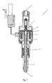
- Figure 1 shows a solenoid injection valve 1 comprising a valve body 2 with a fluid inlet portion 3 and a fluid outlet opening 4 extending along a longitudinal axis L.
- a needle 5 which serves as a fluid flow blocking component blocks the outlet opening 4 by means of interaction with a valve seat.
- the valve seat is integrated in the valve body 2.
- the valve seat and the outlet opening 4 may be comprised by a separate seat element which is fixed to the valve body 2.
- the needle 5 is connected to an armature 6. More specifically, the needle 5 comprises a piston portion and a sealing portion, downstream of the piston portion.
- the piston portion and the sealing portion are arranged coaxially and arranged so that the piston portion can be pressed in longitudinal direction on an upstream end of the sealing portion.
- the piston portion is fixed to the armature.
- the sealing portion is biased by a return spring towards the blocking position.
- the valve 1 comprises a solenoid coil 7 arranged in a housing 8 and a separation disk 9 arranged between the housing 8 and the armature 6.
- the separation disc 9 is comprised by the valve body 2.
- Both the housing 8 and the separation disk 9 are ferromagnetic.
- the development of the magnetic field could be delayed, since a part of the energy introduced into the magnetic field by the solenoid coil 7 may be absorbed by the housing 8 and the separation disk 9 in order to establish a magnetization of said components.
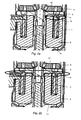
- FIG. 2b A detail of the solenoid valve of Fig.1 according to an exemplary embodiment of the invention is shown in Figure 2b .
- a ferrofluid 14 has been arranged in a gap between the separation disk 9 and the housing 8.
- These components thus have one common magnetic north pole 12 and one common magnetic south pole 13.
- Figure 2a shows a corresponding design with no ferrofluid being arranged in any kind of gap. Due to the surface roughness of the housing 8 and separation disk 9, small gaps (not visible in Fig. 2a ) may be present so that, in particular, each of said components has to be magnetized separately. Therefore, the separation disk and the housing each may have a magnetic north pole 10 and a magnetic south pole 11. In the case of the configuration according to Fig.
- the ferrofluid comprises magnetic particles with an average diameter of 8 nm.
- the particles are coated with citric acid to prevent clumping.
- the gap between the housing 8 and the separation disk 9 has a longitudinal dimension of 100 ⁇ m, i.e., considering the size scale of the gap, the ferrofluid can be considered a homogeneously magnetizable medium.
Landscapes
- Engineering & Computer Science (AREA)
- Physics & Mathematics (AREA)
- Electromagnetism (AREA)
- Chemical & Material Sciences (AREA)
- Combustion & Propulsion (AREA)
- Mechanical Engineering (AREA)
- General Engineering & Computer Science (AREA)
- Power Engineering (AREA)
- Magnetically Actuated Valves (AREA)
Abstract
Description
- The invention concerns an electromagnetically actuatable fluid injection valve.
- Electromagnetically actuatable fluid injection valves are often used for dosing fuel into gasoline or diesel engines.
- Usually, such valves may comprise at least two components which are magnetized during operation of the valve. When the two components are separated by a gap - e . g. due to a surface roughness of said components, due to manufacturing tolerances, due to deformation, due to mounting conditions or due to design requirements - the gap may reduce the magnetic performance of the valve. In particular, the opening transient of the valve may not be as fast as is desirable. In addition, the dimensions of the air gap may be hard to control so that there is a high risk of large part-to-part tolerances. Therefore, the valve opening time may vary from valve to valve, which makes a precise control of the injected amount of fuel difficult.
- It is therefore an object of the invention to provide an improved valve which enables a particularly precise and/or efficient fluid injection. Furthermore, it is an object of the invention to provide a method for producing such a valve.
- These objects are achieved by an electromagnetically actuatable fluid injection valve and a method according to the independent claims. Advantageous embodiments and developments of the fluid injection valve are specified in the dependent claims.
- An electromagnetically actuatable fluid injection valve is specified. Preferably, the fluid injection valve is a fuel injection valve which is in particular configured for dosing fuel directly into a combustion chamber of an internal combustion engine.
- The fluid injection valve comprises a valve body with a fluid inlet portion and a fluid outlet opening. In particular, the valve body has a longitudinal axis. Expediently, the valve body may have a cavity which extends through the valve body in longitudinal direction and hydraulically connects the fluid inlet portion to the fluid outlet opening.
- The fluid injection valve further comprise a fluid flow blocking component - such as a valve needle - which is preferably received in the cavity of the valve body. The fluid flow blocking component is adapted to inhibit a fluid flow between said fluid inlet portion and said fluid outlet opening when arranged in a blocking position, and to allow said fluid flow between said fluid inlet portion and said fluid outlet opening when arranged in a release position. The fluid flow blocking component is in particular axially displaceable relative to the valve body away from the blocking position towards the release position for enabling fluid flow through the fluid outlet opening.
- Additionally, the valve comprises a coil for providing a magnetic field and an armature which is arranged in said magnetic field when an operating current is applied to the coil. The armature is in particular arranged in the cavity and axially displaceable relative to the valve body in reciprocating fashion. The coil is preferably positioned outside of the valve body and positionally fix with respect to the valve body. The coil is in particular a solenoid.
- By means of the magnetic field, the coil is preferably operable to displace the armature, in particular for opening the valve. The armature is mechanically coupled, directly or indirectly, to said fluid flow blocking component in order to move said fluid flow blocking component from the blocking position to the release position - i.e. for opening the valve when the operating current is applied to said coil. It is also conceivable that the electromagnetic actuator assembly comprising the coil and the armature is additionally or alternatively configured for closing the valve, i.e. for displacing the fluid flow blocking component from the release position to the blocking position. However, it is preferred that the fluid flow blocking component is biased towards the blocking position by means of a return spring for closing the valve.
- The fluid injection valve comprises at least two components which are configured and arranged to be magnetized by said coil. The two components are separated from one another by a gap at least in places. The gap is partially or completely filled with a ferrofluid.
- A ferrofluid is in this context a magnetizable fluid and may in particular also be denoted as a superparamagnetic fluid. The ferrofluid has in particular a viscosity which is basically independent of the magnetic field. Preferably, the ferrofluid is a Newtonian fluid with and without exposure to the magnetic field.
- The gap is preferably arranged on a dry side of the valve, i.e., it is preferably not in contact with the fluid flowing through the valve. In other words, the gap is hydraulically separated from the cavity of the valve body.
- The inventors have recognized that the relatively long time required to move the fluid flow blocking element from the blocking position to the release position is caused by an undesirably slow development of the magnetic field when voltage is applied to the coil for feeding the operating current to the coil. It is currently assumed that this undesirably slow development of the field arises from the fact that each component that is separated from other magnetized components has to be magnetized separately. Especially if at least one of the components is relatively flat and arranged such that its dimensions in the direction of the magnetic field lines are small, the magnetization finally achieved may be energetically disadvantageous. That means that the magnetic field has to provide a large amount of energy to the flat component that is to be magnetized in order to establish magnetization. This energy is removed from the field and the magnetic field thus develops at a significantly slower speed. Therefore, the target field strength is reached more slowly than is possible, which increases the time for moving the flowing flow blocking component from the blocking position to the release position.
- The invention makes use of the idea that, through magnetization of the ferrofluid arranged between both components, both components can be magnetized together with said ferrofluid. For establishing this magnetization, significantly less energy is required and, therefore, the target field strength can be established much faster, leading to a faster movement of the fluid flow blocking component from the blocking position to the release position. In addition, the time required to move the fluid flow blocking component from the blocking position to the release position is much more predictable because - due to the ferrofluid filling the gap - fabrication tolerances do not significantly influence the amount of energy required to establish magnetization.
- The valve can be designed to be arranged in the blocking condition when no operating current is applied to the coil. This arrangement is preferable for reasons of safety. However, in general a ferrofluid would provide the same advantages as described above in a valve which is open when no current is applied to the coil.
- According to one embodiment of the valve, a surface roughness of a surface which defines the gap of at least one of said components is between 0.1 µm and 10 µm. In particular, the surface roughness can be between 0.5 µm and 2 µm. The surface roughness is in particular the roughness average Ra which is an amplitude parameter of the surface roughness which is well known to a person skilled in the art.
- In one embodiment, magnetic nanoparticles, in particular ferromagnetic nanoparticles, are contained in the ferrofluid. Preferably, the ferrofluid is a stable colloidal suspension of the magnetic nanoparticles in a carrier fluid. The magnetic nanoparticles may have an average diameter of less than 100 nm. Preferably, their average diameter is less than 50 nm. For example, the average diameter can be between 5 and 10 nm. The average diameter is in this context in particular the median diameter, often denoted as d50, of the nanoparticles. If the nanoparticles are non-spherical, the so-called equivalent diameter of the nanoparticles is used. The measurement of the grain size can be effected by well known standard techniques such as by evaluating a grinding surface or by means of optical measurements.
- In order to provide an optimal magnetic continuity, the nanoparticles responsible for the magnetic properties of the ferrofluid are, according to a possible embodiment, smaller than 1/10, preferably less than 1/20 and most preferably less than 1/50 of the maximal width of the gap and/or of a surface roughness of at least one of said components.
- In order to prevent the nanoparticles contained in the ferrofluid from clumping, said nanoparticles can be coated. As coating, e.g., oleic acid, tetramethylammonium hydroxide, citric acid or soy lecithin may be used.
- The gap has a maximum width of less than 1 mm in one embodiment. Typically, the width is between 10 µm and 500 µm and preferably between 50 µm and 150 µm.
- The at least two components can at least partially comprise or consist of ferromagnetic material. In the context of ferromagnetic components, the use of the ferrofluid in the gap is particularly useful since, due to the strong magnetization achieved in ferromagnetic components, the total energy required to achieve the desired magnetization is relatively large.
- In one embodiment, the valve comprises a housing containing said coil. Expediently, the housing may laterally surround a portion of the valve body.
- In another embodiment, the valve comprises a separator that is arranged between said housing and said armature. The separator may be disc-shaped, i.e. the separator may be a separation disc.
- The separation disc may be comprised by the valve body. The separation disc preferably contributes to seal the fluid inlet portion hydraulically from the housing. For example, the valve body comprises, in axial direction from the fluid inlet portion to the fluid outlet opening, a first tubular portion, the separation disc and a second tubular portion. A cross-sectional area of the cavity of the valve body is preferably larger in the region of the first tubular portion than in the region of the second tubular portion and is in particular reduced in stepped fashion in the region of the separation disc. The second tubular portion is in particular laterally surrounded by the housing. The separation disc preferably extends radially outward from the second tubular portion to the first tubular portion, in particular so as to form a bottom surface of the cavity at a downstream end of the first tubular portion. The main extension plane of the separation disc - i.e. in particular the plane perpendicular to a central rotational axis through the geometric center of gravity of the disc-shape of the separation disc - is preferably perpendicular to the longitudinal axis of the valve body.
- The housing - or a portion of the housing - preferably represents one of said at least two components. The separator may alternatively or additionally represent one of said at least two components. In an expedient development, the housing or the portion of the housing represents a first one of the two components and the separation disc represents a second one of the two components, i.e. the housing and the separation disc are spaced apart from one another by the gap - in particular an axial gap - at least in places. The armature, the separation disc, the gap and the coil preferably follow one another in this order in longitudinal direction towards the fluid outlet opening. The ferrofluid may be expediently arranged between the separation disc and the housing in this case, in particular to partially or completely fill the axial gap.
- In an exemplary method for producing produce a valve according some of the embodiments described above, the housing and the separation disk may be press-fit in a first method step. Afterwards, a ferrofluid is introduced into the gap between the housing and the separation disc. Finally, the gap is sealed by overmolding.
- Further advantages and advantageous embodiments and developments of the fluid injection valve and the method will become apparent and more readily appreciated from the following description of an embodiment of the present invention in connection with the accompanying drawings, in which:
- Fig. 1
- shows a cross-sectional drawing of a solenoid injection valve,
- Fig. 2a
- shows a detail of the solenoid injection valve of
Fig. 1 according to the prior art, and - Fig. 2b
- shows a detail of the valve of
Fig. 1 according to an embodiment of the invention. -
Figure 1 shows asolenoid injection valve 1 comprising avalve body 2 with a fluid inlet portion 3 and a fluid outlet opening 4 extending along a longitudinal axis L. In a blocking position, aneedle 5 which serves as a fluid flow blocking component blocks the outlet opening 4 by means of interaction with a valve seat. In the present embodiment, the valve seat is integrated in thevalve body 2. Alternatively, the valve seat and the outlet opening 4 may be comprised by a separate seat element which is fixed to thevalve body 2. - The
needle 5 is connected to anarmature 6. More specifically, theneedle 5 comprises a piston portion and a sealing portion, downstream of the piston portion. The piston portion and the sealing portion are arranged coaxially and arranged so that the piston portion can be pressed in longitudinal direction on an upstream end of the sealing portion. The piston portion is fixed to the armature. The sealing portion is biased by a return spring towards the blocking position. - In addition to the
needle 5 and thearmature 6, thevalve 1 comprises asolenoid coil 7 arranged in ahousing 8 and aseparation disk 9 arranged between thehousing 8 and thearmature 6. Theseparation disc 9 is comprised by thevalve body 2. By feeding an operating current to thesolenoid coil 7, a magnetic field can be established which moves thearmature 6 longitudinally towards thecoil 7 such that theneedle 5 is axially moved to a release position. - Both the
housing 8 and theseparation disk 9 are ferromagnetic. In a conventional configuration, the development of the magnetic field could be delayed, since a part of the energy introduced into the magnetic field by thesolenoid coil 7 may be absorbed by thehousing 8 and theseparation disk 9 in order to establish a magnetization of said components. - A detail of the solenoid valve of
Fig.1 according to an exemplary embodiment of the invention is shown inFigure 2b . In the embodiment shown inFigure 2b , a ferrofluid 14 has been arranged in a gap between theseparation disk 9 and thehousing 8. These components thus have one commonmagnetic north pole 12 and one commonmagnetic south pole 13.Figure 2a shows a corresponding design with no ferrofluid being arranged in any kind of gap. Due to the surface roughness of thehousing 8 andseparation disk 9, small gaps (not visible inFig. 2a ) may be present so that, in particular, each of said components has to be magnetized separately. Therefore, the separation disk and the housing each may have amagnetic north pole 10 and amagnetic south pole 11. In the case of the configuration according toFig. 2a , to achieve the magnetization condition ofseparation disk 10 may require a particularly large amount of energy, which may be the case because both themagnetic north pole 10 and themagnetic south pole 11 are flat and disk-shaped. Therefore, theseparation disk 10 will absorb a significant amount of field energy after operating voltage has been applied to thesolenoid coil 7. The magnetization condition of the configuration according toFig. 2b is achievable with significantly less energy. Therefore, less energy is absorbed from the magnetic field provided by thesolenoid coil 7. Therefore, the target field distribution is reached significantly faster than without the ferrofluid 14. This leads to a faster movement of theneedle 5 from the blocking position to the release position because the force exerted on thearmature 6 is significantly larger than in the valve shown inFigure 2a . In the embodiment ofFigure 2b , the ferrofluid comprises magnetic particles with an average diameter of 8 nm. The particles are coated with citric acid to prevent clumping. The gap between thehousing 8 and theseparation disk 9 has a longitudinal dimension of 100 µm, i.e., considering the size scale of the gap, the ferrofluid can be considered a homogeneously magnetizable medium.
Claims (13)
- An electromagnetically actuatable fluid injection valve (1) comprising:- a valve body (2) comprising a fluid inlet portion (3) and a fluid outlet opening (4),- a fluid flow blocking component (5) configured to inhibit a fluid flow between said fluid inlet portion (3) and said fluid outlet opening (4) when arranged in a blocking position, and to allow said fluid flow between said fluid inlet portion (3) and said fluid outlet opening (4) when arranged in a release position,- a coil (7) for providing a magnetic field when an operating current is applied to said coil,- an armature (6) arranged in said magnetic field when the operating current is applied to said coil (7), wherein the armature (6) is mechanically coupled to said fluid flow blocking component (5) to move said fluid flow blocking component (5) from the blocking position to the release position or from the release position to the blocking position when said voltage is applied to said coil (7),wherein- the fluid injection valve (1) comprises at least two components (8, 9) configured and arranged to be magnetized by said coil (7),- said at least two components (8, 9) are separated from one another by a gap at least in places, and- said gap is at least partially filled with a ferrofluid (14).
- The valve (1) according to the preceding claim, characterized in that one of said components is a housing (8) containing said coil (7) and laterally surrounding a portion of the valve body (2).
- The valve (1) according to the preceding claim, characterized in that another of said components is a separator, preferably a separation disc (9), arranged between said housing (8) and said armature.
- The valve (1) according to the preceding claim, wherein the separation disc (9) is comprised by the valve body (2) and contributes to hydraulically sealing the fluid inlet portion(3) from the housing (8).
- The valve (1) according to one of claims 3 or 4, wherein a main extension plane of the separation disc (9) is perpendicular to a longitudinal axis (L) of the valve body (2) and the armature (6), the separation disc (9), the gap and the coil (7) follow one another in this order in longitudinal direction towards the fluid outlet opening (4).
- The valve (1) according to one of the preceding claims, wherein the gap containing the ferrofluid (14) is delimited by said two components (8, 9) and an overmolding.
- The valve (1) according to one of the preceding claims, characterized in that the surface roughness of a surface of at least one of said components (8, 9) which defines said gap is between 0.1 µm and 10 µm, preferably between 0.5 µm and 2 µm.
- The valve (1) according to one of the preceding claims, characterized in that the ferrofluid (14) contains ferromagnetic nanoparticles
- The valve (1) according to the preceding claim, wherein the ferromagnetic nanoparticles have an average diameter of less than 100 nm, preferably less than 50 nm and most preferably between 5 and 10 nm.
- The valve (1) according to claim 8 or 9, characterized in that an average diameter of ferromagnetic nanoparticles contained in the ferrofluid (14) is less than 1/10, preferably less than 1/20 and most preferably less than 1/50 of a maximal width of the gap and/or a surface roughness of at least one of said components.
- The valve according to one of claims 8 to 10, characterized in that the ferromagnetic nanoparticles are coated, preferably with an oleic acid, tetramethylammonium hydroxide, citric acid or soy lecithin.
- The valve (1) according to one of the preceding claims, characterized in that the gap has a maximum width of less than 1 mm, preferably a maximum width between 10 µm and 500 µm and most preferably a width between 50 µm and 150 µm.
- A method for producing a valve with at least the features of claims 3 and 6, containing the steps of:1) press-fitting the housing (8) to the separation disc (9),2) introducing the ferrofluid (14) into the gap between the housing (8) and the separation disk (9) and3) sealing the gap by overmolding,wherein the steps are carried out in the sequence 1), 2) and 3).
Priority Applications (1)
| Application Number | Priority Date | Filing Date | Title |
|---|---|---|---|
| EP14158291.6A EP2915991A1 (en) | 2014-03-07 | 2014-03-07 | Electromagnetically actuatable fluid injection valve |
Applications Claiming Priority (1)
| Application Number | Priority Date | Filing Date | Title |
|---|---|---|---|
| EP14158291.6A EP2915991A1 (en) | 2014-03-07 | 2014-03-07 | Electromagnetically actuatable fluid injection valve |
Publications (1)
| Publication Number | Publication Date |
|---|---|
| EP2915991A1 true EP2915991A1 (en) | 2015-09-09 |
Family
ID=50236042
Family Applications (1)
| Application Number | Title | Priority Date | Filing Date |
|---|---|---|---|
| EP14158291.6A Withdrawn EP2915991A1 (en) | 2014-03-07 | 2014-03-07 | Electromagnetically actuatable fluid injection valve |
Country Status (1)
| Country | Link |
|---|---|
| EP (1) | EP2915991A1 (en) |
Citations (4)
| Publication number | Priority date | Publication date | Assignee | Title |
|---|---|---|---|---|
| JPH09213557A (en) * | 1996-02-02 | 1997-08-15 | Nippon Ceramic Co Ltd | Processing method of facing surface of magnetic body |
| WO2001039217A1 (en) * | 1999-11-25 | 2001-05-31 | Nanomagnetics Limited | Magnetic fluid |
| US20020056768A1 (en) * | 2000-11-13 | 2002-05-16 | Czimmek Perry Robert | Magneto-hydraulic compensator for a fuel injector |
| US7942349B1 (en) * | 2009-03-24 | 2011-05-17 | Meyer Andrew E | Fuel injector |
-
2014
- 2014-03-07 EP EP14158291.6A patent/EP2915991A1/en not_active Withdrawn
Patent Citations (4)
| Publication number | Priority date | Publication date | Assignee | Title |
|---|---|---|---|---|
| JPH09213557A (en) * | 1996-02-02 | 1997-08-15 | Nippon Ceramic Co Ltd | Processing method of facing surface of magnetic body |
| WO2001039217A1 (en) * | 1999-11-25 | 2001-05-31 | Nanomagnetics Limited | Magnetic fluid |
| US20020056768A1 (en) * | 2000-11-13 | 2002-05-16 | Czimmek Perry Robert | Magneto-hydraulic compensator for a fuel injector |
| US7942349B1 (en) * | 2009-03-24 | 2011-05-17 | Meyer Andrew E | Fuel injector |
Similar Documents
| Publication | Publication Date | Title |
|---|---|---|
| CN103180918B (en) | Electromagnetic devices and driver assistance devices | |
| US20130113583A1 (en) | Protected powder metal stator core and solenoid actuator using same | |
| CN102086826B (en) | Electromagnetic valve for controlling fuel injector or for regulating pressure of high-pressure fuel accumulator | |
| US8690118B2 (en) | Solenoid actuated device and methods | |
| EP2535552A1 (en) | Valve assembly for an injection valve and injection valve | |
| CN102959649B (en) | Reduce armature by the delay cell in residual gap and close rebound | |
| CN105745433A (en) | Valve for metering fluid | |
| JP2004360750A (en) | solenoid valve | |
| EP2436908A1 (en) | Valve assembly for an injection valve and injection valve | |
| EP2985445A1 (en) | Solenoid actuated fluid injection valve | |
| CN109313973A (en) | Electromagnetic Actuators with Integral Pole Pieces | |
| CN108799603A (en) | Electromagnetic actuators | |
| CN103026428B (en) | Electromagnetic actuators | |
| CN102084165A (en) | Air gap boundary for electromagnetic valve | |
| CN108368805A (en) | Valve module and injection valve for injection valve | |
| CN105579696B (en) | Fluid injection valve | |
| CN103097713B (en) | fuel injection valve | |
| CN106545682B (en) | Solenoid valve comprising armature with movable step | |
| EP2589786A1 (en) | Valve assembly for a control valve and control valve | |
| EP3362669B1 (en) | Electromagnetic injection valve and method for assembling an electromagnetic injection valve | |
| EP3339628A1 (en) | Valve assembly for an injection valve and injection valve | |
| EP3034853B1 (en) | Coil assembly and fluid injection valve | |
| JP2003328891A (en) | Fuel injection device | |
| EP3263884A1 (en) | Injection valve with a magnetic ring element | |
| CN108700220B (en) | The electromagnetic valve |
Legal Events
| Date | Code | Title | Description |
|---|---|---|---|
| PUAI | Public reference made under article 153(3) epc to a published international application that has entered the european phase |
Free format text: ORIGINAL CODE: 0009012 |
|
| AK | Designated contracting states |
Kind code of ref document: A1 Designated state(s): AL AT BE BG CH CY CZ DE DK EE ES FI FR GB GR HR HU IE IS IT LI LT LU LV MC MK MT NL NO PL PT RO RS SE SI SK SM TR |
|
| AX | Request for extension of the european patent |
Extension state: BA ME |
|
| 17P | Request for examination filed |
Effective date: 20160309 |
|
| RBV | Designated contracting states (corrected) |
Designated state(s): AL AT BE BG CH CY CZ DE DK EE ES FI FR GB GR HR HU IE IS IT LI LT LU LV MC MK MT NL NO PL PT RO RS SE SI SK SM TR |
|
| GRAP | Despatch of communication of intention to grant a patent |
Free format text: ORIGINAL CODE: EPIDOSNIGR1 |
|
| RIC1 | Information provided on ipc code assigned before grant |
Ipc: H01F 1/44 20060101ALI20160414BHEP Ipc: F02M 51/06 20060101AFI20160414BHEP Ipc: F02M 61/08 20060101ALN20160414BHEP |
|
| INTG | Intention to grant announced |
Effective date: 20160518 |
|
| STAA | Information on the status of an ep patent application or granted ep patent |
Free format text: STATUS: THE APPLICATION IS DEEMED TO BE WITHDRAWN |
|
| 18D | Application deemed to be withdrawn |
Effective date: 20160929 |