EP2915983A1 - Control device and control method for internal combustion engine - Google Patents
Control device and control method for internal combustion engine Download PDFInfo
- Publication number
- EP2915983A1 EP2915983A1 EP12887331.2A EP12887331A EP2915983A1 EP 2915983 A1 EP2915983 A1 EP 2915983A1 EP 12887331 A EP12887331 A EP 12887331A EP 2915983 A1 EP2915983 A1 EP 2915983A1
- Authority
- EP
- European Patent Office
- Prior art keywords
- fuel
- excess ratio
- air excess
- injection pressure
- spray air
- Prior art date
- Legal status (The legal status is an assumption and is not a legal conclusion. Google has not performed a legal analysis and makes no representation as to the accuracy of the status listed.)
- Granted
Links
Images


Classifications
-
- F—MECHANICAL ENGINEERING; LIGHTING; HEATING; WEAPONS; BLASTING
- F02—COMBUSTION ENGINES; HOT-GAS OR COMBUSTION-PRODUCT ENGINE PLANTS
- F02D—CONTROLLING COMBUSTION ENGINES
- F02D41/00—Electrical control of supply of combustible mixture or its constituents
- F02D41/0025—Controlling engines characterised by use of non-liquid fuels, pluralities of fuels, or non-fuel substances added to the combustible mixtures
- F02D41/0047—Controlling exhaust gas recirculation [EGR]
- F02D41/005—Controlling exhaust gas recirculation [EGR] according to engine operating conditions
- F02D41/0052—Feedback control of engine parameters, e.g. for control of air/fuel ratio or intake air amount
-
- F—MECHANICAL ENGINEERING; LIGHTING; HEATING; WEAPONS; BLASTING
- F02—COMBUSTION ENGINES; HOT-GAS OR COMBUSTION-PRODUCT ENGINE PLANTS
- F02D—CONTROLLING COMBUSTION ENGINES
- F02D41/00—Electrical control of supply of combustible mixture or its constituents
- F02D41/02—Circuit arrangements for generating control signals
- F02D41/14—Introducing closed-loop corrections
- F02D41/1438—Introducing closed-loop corrections using means for determining characteristics of the combustion gases; Sensors therefor
- F02D41/1439—Introducing closed-loop corrections using means for determining characteristics of the combustion gases; Sensors therefor characterised by the position of the sensor
- F02D41/144—Sensor in intake manifold
-
- F—MECHANICAL ENGINEERING; LIGHTING; HEATING; WEAPONS; BLASTING
- F02—COMBUSTION ENGINES; HOT-GAS OR COMBUSTION-PRODUCT ENGINE PLANTS
- F02D—CONTROLLING COMBUSTION ENGINES
- F02D41/00—Electrical control of supply of combustible mixture or its constituents
- F02D41/02—Circuit arrangements for generating control signals
- F02D41/14—Introducing closed-loop corrections
- F02D41/1438—Introducing closed-loop corrections using means for determining characteristics of the combustion gases; Sensors therefor
- F02D41/1444—Introducing closed-loop corrections using means for determining characteristics of the combustion gases; Sensors therefor characterised by the characteristics of the combustion gases
- F02D41/1454—Introducing closed-loop corrections using means for determining characteristics of the combustion gases; Sensors therefor characterised by the characteristics of the combustion gases the characteristics being an oxygen content or concentration or the air-fuel ratio
-
- F—MECHANICAL ENGINEERING; LIGHTING; HEATING; WEAPONS; BLASTING
- F02—COMBUSTION ENGINES; HOT-GAS OR COMBUSTION-PRODUCT ENGINE PLANTS
- F02D—CONTROLLING COMBUSTION ENGINES
- F02D41/00—Electrical control of supply of combustible mixture or its constituents
- F02D41/02—Circuit arrangements for generating control signals
- F02D41/14—Introducing closed-loop corrections
- F02D41/1438—Introducing closed-loop corrections using means for determining characteristics of the combustion gases; Sensors therefor
- F02D41/1444—Introducing closed-loop corrections using means for determining characteristics of the combustion gases; Sensors therefor characterised by the characteristics of the combustion gases
- F02D41/1454—Introducing closed-loop corrections using means for determining characteristics of the combustion gases; Sensors therefor characterised by the characteristics of the combustion gases the characteristics being an oxygen content or concentration or the air-fuel ratio
- F02D41/1458—Introducing closed-loop corrections using means for determining characteristics of the combustion gases; Sensors therefor characterised by the characteristics of the combustion gases the characteristics being an oxygen content or concentration or the air-fuel ratio with determination means using an estimation
-
- F—MECHANICAL ENGINEERING; LIGHTING; HEATING; WEAPONS; BLASTING
- F02—COMBUSTION ENGINES; HOT-GAS OR COMBUSTION-PRODUCT ENGINE PLANTS
- F02D—CONTROLLING COMBUSTION ENGINES
- F02D41/00—Electrical control of supply of combustible mixture or its constituents
- F02D41/30—Controlling fuel injection
- F02D41/38—Controlling fuel injection of the high pressure type
-
- F—MECHANICAL ENGINEERING; LIGHTING; HEATING; WEAPONS; BLASTING
- F02—COMBUSTION ENGINES; HOT-GAS OR COMBUSTION-PRODUCT ENGINE PLANTS
- F02D—CONTROLLING COMBUSTION ENGINES
- F02D41/00—Electrical control of supply of combustible mixture or its constituents
- F02D41/30—Controlling fuel injection
- F02D41/38—Controlling fuel injection of the high pressure type
- F02D41/3809—Common rail control systems
- F02D41/3836—Controlling the fuel pressure
-
- G—PHYSICS
- G01—MEASURING; TESTING
- G01M—TESTING STATIC OR DYNAMIC BALANCE OF MACHINES OR STRUCTURES; TESTING OF STRUCTURES OR APPARATUS, NOT OTHERWISE PROVIDED FOR
- G01M15/00—Testing of engines
- G01M15/04—Testing internal-combustion engines
- G01M15/10—Testing internal-combustion engines by monitoring exhaust gases or combustion flame
- G01M15/102—Testing internal-combustion engines by monitoring exhaust gases or combustion flame by monitoring exhaust gases
- G01M15/106—Testing internal-combustion engines by monitoring exhaust gases or combustion flame by monitoring exhaust gases using pressure sensors
-
- F—MECHANICAL ENGINEERING; LIGHTING; HEATING; WEAPONS; BLASTING
- F02—COMBUSTION ENGINES; HOT-GAS OR COMBUSTION-PRODUCT ENGINE PLANTS
- F02D—CONTROLLING COMBUSTION ENGINES
- F02D2200/00—Input parameters for engine control
- F02D2200/02—Input parameters for engine control the parameters being related to the engine
- F02D2200/06—Fuel or fuel supply system parameters
- F02D2200/0602—Fuel pressure
-
- F—MECHANICAL ENGINEERING; LIGHTING; HEATING; WEAPONS; BLASTING
- F02—COMBUSTION ENGINES; HOT-GAS OR COMBUSTION-PRODUCT ENGINE PLANTS
- F02D—CONTROLLING COMBUSTION ENGINES
- F02D2250/00—Engine control related to specific problems or objectives
- F02D2250/18—Control of the engine output torque
- F02D2250/21—Control of the engine output torque during a transition between engine operation modes or states
-
- F—MECHANICAL ENGINEERING; LIGHTING; HEATING; WEAPONS; BLASTING
- F02—COMBUSTION ENGINES; HOT-GAS OR COMBUSTION-PRODUCT ENGINE PLANTS
- F02D—CONTROLLING COMBUSTION ENGINES
- F02D2250/00—Engine control related to specific problems or objectives
- F02D2250/31—Control of the fuel pressure
-
- F—MECHANICAL ENGINEERING; LIGHTING; HEATING; WEAPONS; BLASTING
- F02—COMBUSTION ENGINES; HOT-GAS OR COMBUSTION-PRODUCT ENGINE PLANTS
- F02D—CONTROLLING COMBUSTION ENGINES
- F02D2250/00—Engine control related to specific problems or objectives
- F02D2250/32—Air-fuel ratio control in a diesel engine
-
- F—MECHANICAL ENGINEERING; LIGHTING; HEATING; WEAPONS; BLASTING
- F02—COMBUSTION ENGINES; HOT-GAS OR COMBUSTION-PRODUCT ENGINE PLANTS
- F02D—CONTROLLING COMBUSTION ENGINES
- F02D2250/00—Engine control related to specific problems or objectives
- F02D2250/38—Control for minimising smoke emissions, e.g. by applying smoke limitations on the fuel injection amount
-
- F—MECHANICAL ENGINEERING; LIGHTING; HEATING; WEAPONS; BLASTING
- F02—COMBUSTION ENGINES; HOT-GAS OR COMBUSTION-PRODUCT ENGINE PLANTS
- F02M—SUPPLYING COMBUSTION ENGINES IN GENERAL WITH COMBUSTIBLE MIXTURES OR CONSTITUENTS THEREOF
- F02M26/00—Engine-pertinent apparatus for adding exhaust gases to combustion-air, main fuel or fuel-air mixture, e.g. by exhaust gas recirculation [EGR] systems
- F02M26/13—Arrangement or layout of EGR passages, e.g. in relation to specific engine parts or for incorporation of accessories
- F02M26/22—Arrangement or layout of EGR passages, e.g. in relation to specific engine parts or for incorporation of accessories with coolers in the recirculation passage
- F02M26/23—Layout, e.g. schematics
-
- Y—GENERAL TAGGING OF NEW TECHNOLOGICAL DEVELOPMENTS; GENERAL TAGGING OF CROSS-SECTIONAL TECHNOLOGIES SPANNING OVER SEVERAL SECTIONS OF THE IPC; TECHNICAL SUBJECTS COVERED BY FORMER USPC CROSS-REFERENCE ART COLLECTIONS [XRACs] AND DIGESTS
- Y02—TECHNOLOGIES OR APPLICATIONS FOR MITIGATION OR ADAPTATION AGAINST CLIMATE CHANGE
- Y02T—CLIMATE CHANGE MITIGATION TECHNOLOGIES RELATED TO TRANSPORTATION
- Y02T10/00—Road transport of goods or passengers
- Y02T10/10—Internal combustion engine [ICE] based vehicles
- Y02T10/40—Engine management systems
Definitions
- the present invention relates to an internal combustion engine control apparatus and a control method thereof.
- a method for controlling an air excess ratio to an appropriate value is known as one of methods for reducing smoke, dust and/or the like.
- PTL 1 discloses a method for estimating a flowing state of an in-cylinder gas of an internal combustion engine, taking into account the estimated flowing state of the in-cylinder gas to estimate a value equivalent to a concentration of an air-fuel mixture of fuel and intake air as an air-fuel mixture concentration equivalent value, and adjusting engine control parameters (e.g., fuel injection timing, fuel injection pressure, amount of fuel injection, amount of exhaust gas recirculation) so that the estimated air-fuel mixture concentration equivalent value matches a predetermined concentration.
- engine control parameters e.g., fuel injection timing, fuel injection pressure, amount of fuel injection, amount of exhaust gas recirculation
- an engine using an exhaust gas recirculation (EGR) scheme may increase the air excess ratio to a target value by closing an EGR valve. In this case, however, there is inconvenience that an intake oxygen molar concentration rises and the amount of NOx generated increases.
- the present invention has been made in view of the above-described circumstances and it is an object of the present invention to provide an internal combustion engine control apparatus and a control method thereof capable of improving estimation accuracy of an air excess ratio within a fuel spray (hereinafter referred to as "in-fuel-spray air excess ratio”) and quickly causing the in-fuel-spray air excess ratio to approximate to a target value when the engine load factor rises.
- in-fuel-spray air excess ratio an air excess ratio within a fuel spray
- a first aspect of the present invention is an internal combustion engine control apparatus including an information acquiring means configured to acquire an air intake parameter relating to intake air including an intake oxygen molar concentration and a fuel parameter relating to fuel injection, a first estimating means configured to estimate an in-fuel-spray air excess ratio using the air intake parameter and the fuel parameter, a first determining means configured to determine whether or not the in-fuel-spray air excess ratio is equal to or higher than a preset predetermined target in-fuel-spray air excess ratio, a pressure calculating means configured to calculate, when the in-fuel-spray air excess ratio is determined to be less than the target in-fuel-spray air excess ratio, a necessary fuel injection pressure to match the in-fuel-spray air excess ratio with the target in-fuel-spray air excess ratio, and a second determining means configured to determine whether or not the necessary fuel injection pressure is equal to or less than a preset maximum injection pressure, in which when the necessary fuel injection pressure is determined to be equal to or less than the maximum injection
- a second aspect of the present invention is the internal combustion engine control apparatus applied to an internal combustion engine adopting an exhaust gas recirculation scheme in which part of an exhaust gas of the engine is circulated into an air intake system, the apparatus further including a second estimating means configured to estimate, when the second determining means determines that the maximum injection pressure is exceeded, an in-fuel-spray air excess ratio when the maximum injection pressure is set as the fuel injection pressure, and an oxygen molar concentration calculating means configured to calculate a necessary intake oxygen molar concentration to match the in-fuel-spray air excess ratio estimated by the second estimating means with the target in-fuel-spray air excess ratio, in which when the necessary fuel injection pressure is determined to exceed the maximum injection pressure, fuel injection is performed at the maximum injection pressure and the amount of exhaust gas to be circulated into the air intake system is controlled based on the necessary intake oxygen molar concentration.
- the amount of exhaust gas to be circulated into the air intake system may be set to 0.
- a third aspect of the present invention is an internal combustion engine control method including an information acquiring step of acquiring an air intake parameter relating to intake air including an intake oxygen molar concentration and a fuel parameter relating to fuel injection, a first estimating step of estimating an in-fuel-spray air excess ratio using the air intake parameter and the fuel parameter, a first determining step of determining whether or not the in-fuel-spray air excess ratio is equal to or higher than a preset predetermined target in-fuel-spray air excess ratio, a pressure calculating step of calculating, when the in-fuel-spray air excess ratio is determined to be less than the target in-fuel-spray air excess ratio, a necessary fuel injection pressure to match the in-fuel-spray air excess ratio with the target in-fuel-spray air excess ratio, and a second determining step of determining whether or not the necessary fuel injection pressure is equal to or less than a preset maximum injection pressure, in which when the necessary fuel injection pressure is determined to be equal to or less than the maximum injection
- the present invention provides an effect of improving estimation accuracy of the in-fuel-spray air excess ratio and being able to quickly causing the in-fuel-spray air excess ratio to approximate to a target value when the engine load factor rises.
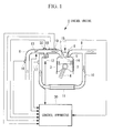
- Fig. 1 is a diagram illustrating a schematic configuration of an internal combustion engine when a diesel engine is adopted as an example of an internal combustion engine.
- a diesel engine hereinafter referred to as "engine”
- engine 1 is provided with a piston 3 fitted in a cylinder 2 so as to slidably reciprocate and a crank shaft (not shown) that converts the reciprocating motion of the piston 3 to rotation via a connecting rod 4.
- a combustion chamber 5 is formed as a compartment between a top surface of the piston 3 and an inner surface of the cylinder 2.
- An intake passage 6 is connected to the combustion chamber 5 and an air intake valve 7 for opening/closing an air intake port is provided therein.
- an exhaust passage 8 is connected to the combustion chamber 5 and an exhaust valve 9 for opening/closing an exhaust port is provided therein.
- An EGR (exhaust gas recirculation) passage 10 is connected at some midpoint of the exhaust passage 8 for recirculating part of the exhaust gas that circulates along the exhaust passage 8 back to the intake passage 6.
- the EGR passage 10 is provided with an EGR cooler 11 that cools the EGR gas and an EGR valve 12 that controls an EGR gas flow rate.
- An air intake throttle valve 13 is provided upstream in the air flow of the connection part of the EGR passage 10 in the intake passage 6.
- a Fuel injection nozzle 14 that injects a fuel which is highly pressurized by a fuel injection pump (not shown) into the combustion chamber 5 is provided in the combustion chamber 5.
- a common rail scheme may be adopted which can change a fuel injection pressure according to an engine operating condition through electronic control.
- the amount of fuel injection and injection timing by the Fuel injection nozzle 14 are controlled by a control apparatus 30, which will be described later, controlling a Fuel injector 15 provided upstream of the Fuel injection nozzle 14 in the fuel flow.
- An air flow meter 16 for detecting an amount of air intake into the combustion chamber 5 through the intake passage 6 is provided upstream of the air intake throttle valve 13 of the intake passage 6 in the air flow.
- An intake manifold at a distal end portion on the combustion chamber 5 side of the intake passage 6 is provided with an intake manifold pressure sensor 18, an intake manifold temperature sensor 19, and an intake manifold oxygen molar concentration sensor 20 for respectively detecting a pressure, temperature, oxygen molar concentration in the intake manifold.
- Measured values of the air flow meter 16, intake manifold pressure sensor 18, intake manifold temperature sensor 19, and intake manifold oxygen molar concentration sensor 20 are inputted to the control apparatus 30.
- the control apparatus 30 is, for example, a microcomputer and is provided with a central processing unit 31, a main storage 32 such as RAM (Random Access Memory), an auxiliary storage 33, an output device 34, an input device 35, and a communication device 36 that exchanges information by carrying out communication with an external device or the like as shown in Fig. 2 .
- main storage 32 such as RAM (Random Access Memory)
- auxiliary storage 33 such as RAM (Random Access Memory)
- an output device 34 such as an input device 35
- a communication device 36 that exchanges information by carrying out communication with an external device or the like as shown in Fig. 2 .
- the auxiliary storage 33 is a computer-readable recording medium and is, for example, a magnetic disk, magneto-optical disk, CD-ROM, DVD-ROM or semiconductor memory.
- the auxiliary storage 33 stores various programs (e.g., in-fuel-spray air excess ratio control program), and the central processing unit 31 reads a program from the auxiliary storage 33 into the main storage 32 and executes the program to thereby implement various kinds of processing.
- the control apparatus 30 is provided with an in-fuel-spray air excess ratio control function that controls the in-fuel-spray air excess ratio in the combustion chamber 5.
- Fig. 3 is a diagram illustrating function blocks relating to the in-fuel-spray air excess ratio control function among various functions provided for the control apparatus 30.
- the control apparatus 30 is provided with an information acquiring section 41, a first estimation section 42, a first determining section 43, a pressure calculation section 44, a second determining section 45, a second estimation section 46, an oxygen molar concentration calculation section 47, and a third determining section 48.
- the information acquiring section 41 acquires various parameters necessary to calculate an in-fuel-spray air excess ratio. More specifically, the information acquiring section 41 acquires air intake parameters relating to intake air including an intake oxygen molar concentration and fuel parameters relating to fuel injection. Examples of the air intake parameters include intake oxygen molar concentration, air intake pressure and air intake temperature measured by the intake manifold oxygen molar concentration sensor 20, intake manifold pressure sensor 18, and intake manifold temperature sensor 19. Examples of the fuel parameters include fuel injection pressure and fuel ignition delay. These parameters are acquired based on, for example, a command value used for the control apparatus 30 to control the fuel injection apparatus.
- the first estimation section 42 calculates the in-fuel-spray air excess ratio using the air intake parameters and fuel parameters acquired by the information acquiring section 41 and a preset predetermined value set in advance.
- the first estimation section 42 has in-fuel-spray air excess ratio estimation arithmetic expressions for estimating an in-fuel-spray air excess ratio based on a fuel spray travel of the fuel in advance as shown below and calculates the in-fuel-spray air excess ratio by using the above various parameters for these arithmetic expressions.
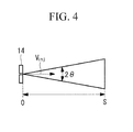
- the arithmetic expressions shown below correspond to a technique of calculating the air excess ratio within the fuel spray by calculating a fuel spray travel S at the time of fuel ignition t ign and assuming that the fuel spray is formed in a conical shape as shown in Fig. 4 .
- the technique of calculating the in-fuel-spray air excess ratio is not limited to this method.
- the intake oxygen molar concentration needs to be included as a parameter.
- the first estimation section 42 calculates a cylinder pressure at a top dead center P comp ⁇ Pa ⁇ , difference between a fuel injection pressure and a cylinder pressure ⁇ P ⁇ Pa ⁇ , cylinder temperature at the top dead center T comp ⁇ K ⁇ , fuel injection speed V inj ⁇ m/s ⁇ , cylinder air density at the top dead center ⁇ a ⁇ kg/m 3 ⁇ , nozzle cross-sectional area per orifice A noz ⁇ m 2 ⁇ , fuel spray travel S ⁇ m ⁇ and fuel spray volume Vol sp ⁇ m 3 ⁇ , using an air intake pressure P inmam ⁇ Pa ⁇ , fuel injection pressure P inj ⁇ Pa ⁇ , air intake temperature T inmani ⁇ K ⁇ , intake oxygen molar concentration O 2_intake ⁇ % ⁇ and fuel injection period t acquired by the information acquiring section 41, and preset compression ratio ⁇ , nozzle orifice diameter d noz , fuel density ⁇ f ⁇ kg/m 3 ⁇ , specific heat ratio k, nozzle flow coefficient
- the fuel spray travel S ⁇ m ⁇ is calculated using expression (7) when the fuel injection period t is equal to or less than t b defined in expression (9) and the fuel spray travel S ⁇ m ⁇ is calculated using expression (8) when the fuel injection period t is higher than t b .
- the first estimation section 42 calculates a theoretical air-fuel ratio L from an intake oxygen molar concentration O 2_intake ⁇ % ⁇ . For example, when the oxygen molar concentration in the air is 20.9%, the theoretical air-fuel ratio L 0 is expressed by following expression (12) based on expression (A.24) of Annex A of JIS B8008-1:2009. The unit is an amount of air ⁇ kg ⁇ necessary per kg of the fuel.
- ⁇ c,mass represents a carbon mass ratio ⁇ - ⁇ in the fuel
- ⁇ H,mass represents a hydrogen mass ratio ⁇ - ⁇ in the fuel
- ⁇ S,mass represents a sulfur mass ratio ⁇ - ⁇ in the fuel.
- ⁇ c,mass 0.87 ⁇ - ⁇
- ⁇ H,mass 0.13 ⁇ - ⁇
- L 0 14.47 is obtained. Note that this value applies to a case where an oxygen molar concentration in the air is 20.9%.
- the first determining section 43 determines whether or not the in-fuel-spray air excess ratio ⁇ SP calculated by the first estimation section 42 is equal to or higher than a preset predetermined target in-fuel-spray air excess ratio ⁇ SP *.
- the target in-fuel-spray air excess ratio is a value determined according to an air excess ratio during steady operation.
- the pressure calculation section 44 calculates a necessary fuel injection pressure P inj_new to match the in-fuel-spray air excess ratio ⁇ SP with the target in-fuel-spray air excess ratio ⁇ SP *.
- the second determining section 45 determines whether or not the necessary fuel injection pressure P inj_new is equal to or less than a preset maximum injection pressure.
- the maximum injection pressure is set to a maximum injection pressure determined, for example, by a mechanical structure of the fuel injection apparatus.
- the second estimation section 46 estimates the in-fuel-spray air excess ratio ⁇ SP_pmax when the maximum injection pressure is set as a fuel injection pressure. More specifically, the in-fuel-spray air excess ratio when the maximum injection pressure is set as the fuel injection pressure P inj ⁇ Pa ⁇ is calculated using the above expressions (1) to (12). The other parameters are similar to those in the above first estimation section 42.
- the oxygen molar concentration calculation section 47 calculates a necessary intake oxygen molar concentration O2 _new to match the in-fuel-spray air excess ratio ⁇ SP_pmax estimated by the second estimation section 46 with the target in-fuel-spray air excess ratio. For example, such an intake oxygen molar concentration that allows the in-fuel-spray air excess ratio ⁇ SP_pmax to match the target in-fuel-spray air excess ratio ⁇ SP * is calculated as the necessary intake oxygen molar concentration O2 _new from aforementioned expression (12) or the like.
- the third determining section 48 determines whether or not the necessary intake oxygen molar concentration O2 _new calculated by the oxygen molar concentration calculation section 47 is equal to or less than the concentration upper limit value set based on the oxygen molar concentration in the atmosphere.
- the concentration upper limit value is, for example, 21%.
- the control apparatus 30 controls the fuel injection pressure and the valve opening position of the EGR valve 12 based on the determination result of the above first determining section 42 or the like according to following (A) to (D).
- step SA1 various kinds of input information (air intake parameters, fuel parameters or the like) to calculate the in-fuel-spray air excess ratio are acquired (step SA1) and the in-fuel-spray air excess ratio ⁇ sp is calculated using the various kinds of input information (step SA2).
- step SA3 it is determined whether or not the in-fuel-spray air excess ratio ⁇ sp is equal to or higher than the target in-fuel-spray air excess ratio ⁇ sp * (step SA3), and if the in-fuel-spray air excess ratio ⁇ sp is equal to or higher than the target in-fuel-spray air excess ratio ("YES" in step SA3), the current control is maintained without particularly changing the fuel injection pressure and the EGR valve opening position (step SA4) .
- step SA5 if the in-fuel-spray air excess ratio ⁇ sp is less than the target in-fuel-spray air excess ratio ⁇ SP * ("No" in step SA3), such a fuel injection pressure that causes the in-fuel-spray air excess ratio ⁇ sp to match the target in-fuel-spray air excess ratio ⁇ SP * is calculated as the necessary fuel injection pressure P inj_new (step SA5).
- step SA6 it is determined whether or not the necessary fuel injection pressure P inj_new is equal to or less than the maximum injection pressure.
- the determination result shows that the necessary fuel injection pressure P inj_new is equal to or less than the maximum injection pressure ("YES" in step SA6)
- the current control of the valve opening position of the EGR valve is maintained and fuel injection is controlled by setting the fuel injection pressure to the necessary fuel injection pressure P inj_new (step SA7).
- step SA6 when the necessary fuel injection pressure P inj_new exceeds the maximum injection pressure ("NO" in step SA6), a maximum injection pressure is set as the fuel injection pressure (step SA8), and the in-fuel-spray air excess ratio ⁇ SP_pmax in this case is estimated (step SA9).
- a necessary intake oxygen molar concentration O 2_new to match the in-fuel-spray air excess ratio ⁇ SP_pmax with the target in-fuel-spray air excess ratio ⁇ SP * is calculated (step SA10) and it is determined whether or not this necessary intake oxygen molar concentration O 2_new is equal to or less than the concentration upper limit value set based on the oxygen molar concentration in the atmosphere (step SA11).
- the fuel injection is controlled by setting the fuel injection pressure to the necessary fuel injection pressure P inj_new and the valve opening position of the EGR valve 12 is controlled so that the intake oxygen molar concentration matches the necessary intake oxygen molar concentration O 2_new (step SA12).
- the concentration upper limit value e.g. 21% which is oxygen molar concentration in the atmosphere
- step SA11 when the necessary intake oxygen molar concentration O 2_new exceeds the concentration upper limit value ("NO" in step SA11), the fuel injection is controlled by setting the fuel injection pressure to the necessary fuel injection pressure P inj_new and the EGR valve is fully closed (step SA13).
- the control apparatus 30 repeatedly executes above step SA1 to step SA11 at a predetermined time interval and thereby executes fuel injection control and valve opening position control of the EGR valve 12 so that the in-fuel-spray air excess ratio matches or approximates to the target in-fuel-spray air excess ratio ⁇ SP *.
- the in-fuel-spray air excess ratio is estimated by taking into account the intake oxygen molar concentration, and it is thereby possible to improve the estimation accuracy of the in-fuel-spray air excess ratio.
- the fuel injection pressure is controlled so that the estimated in-fuel-spray air excess ratio matches the target in-fuel-spray air excess ratio.
- the in-fuel-spray air excess ratio is increased by controlling the fuel injection pressure in particular among the various parameters whose control allows the in-fuel-spray air excess ratio to be increased (e.g., amount of fuel injection, EGR valve opening position). This allows the in-fuel-spray air excess ratio to quickly match or approximate to the target in-fuel-spray air excess ratio while avoiding, for example, a decrease in the torque or an increase in the amount of NOx.
- the oxygen molar concentration is measured using the aforementioned intake manifold oxygen molar concentration sensor 20, but instead of this, the oxygen molar concentration can also be estimated using the amount of EGR gas and the air excess ratio.
- the method of estimating an oxygen molar concentration will be described.
- an intake oxygen molar concentration ⁇ % ⁇ is expressed by following expression (15).
- O 2 O 2 _ air ⁇ 1 - R ⁇
- O 2 is intake oxygen molar concentration ⁇ % ⁇
- O 2_air oxygen molar concentration ⁇ % ⁇ in the air
- R is an EGR rate ⁇ - ⁇
- ⁇ is air excess ratio ⁇ - ⁇ .
- the EGR gas rate is a value obtained by dividing the amount of EGR gas calculated from a difference between the total amount of gas taken into the cylinder and the amount of air by the total amount of gas taken into the cylinder.
- the amount of air before compression is used.
- the amount of gas taken into the cylinder is calculated from a function of a pressure and a gas temperature at the intake manifold based on an equation of state of the gas and the energy conservation law. Furthermore, the air excess ratio can be calculated from a pressure and gas temperature at the intake manifold and a measured value of the air flow meter provided upstream of the compressor in the air flow.
Landscapes
- Engineering & Computer Science (AREA)
- Chemical & Material Sciences (AREA)
- Combustion & Propulsion (AREA)
- Mechanical Engineering (AREA)
- General Engineering & Computer Science (AREA)
- Physics & Mathematics (AREA)
- General Physics & Mathematics (AREA)
- Electrical Control Of Air Or Fuel Supplied To Internal-Combustion Engine (AREA)
- Combined Controls Of Internal Combustion Engines (AREA)
- Output Control And Ontrol Of Special Type Engine (AREA)
Abstract
Description
- The present invention relates to an internal combustion engine control apparatus and a control method thereof.
- It is generally known that an exhaust gas of an internal combustion engine such as a diesel engine contains harmful substances such as NOx, SOx and smoke and dust or substances that apply load to the environment. Thus, various schemes have been proposed for reducing such substances.
- Conventionally, a method for controlling an air excess ratio to an appropriate value is known as one of methods for reducing smoke, dust and/or the like.
- For example,
PTL 1 discloses a method for estimating a flowing state of an in-cylinder gas of an internal combustion engine, taking into account the estimated flowing state of the in-cylinder gas to estimate a value equivalent to a concentration of an air-fuel mixture of fuel and intake air as an air-fuel mixture concentration equivalent value, and adjusting engine control parameters (e.g., fuel injection timing, fuel injection pressure, amount of fuel injection, amount of exhaust gas recirculation) so that the estimated air-fuel mixture concentration equivalent value matches a predetermined concentration. - Japanese Unexamined Patent Application, Publication No.
2005-226460 - However, since an oxygen molar concentration of the intake air is not taken into consideration in the method disclosed in above
PTL 1, when an EGR is introduced, that is, when the oxygen molar concentration changes, the estimation accuracy of the air excess ratio unfortunately decreases. - In the case of the internal combustion engine, when an engine load factor rises suddenly, the response of a supercharger delays, and so the amount of air in the combustion chamber decreases with respect to the same fuel injection amount compared to that in steady operation. This causes the air excess ratio to deteriorate, making it more likely to produce smoke, dust and/or the like.
- For this reason, when the engine load factor rises suddenly, it is necessary to quickly increase the air excess ratio so as to reach a target value. Generally, there can be a method for reducing the amount of fuel injection and increasing the air excess ratio, but such a method causes the amount of torque generated to reduce, causing the output response of the engine to deteriorate, and is therefore not desirable. On the other hand, an engine using an exhaust gas recirculation (EGR) scheme may increase the air excess ratio to a target value by closing an EGR valve. In this case, however, there is inconvenience that an intake oxygen molar concentration rises and the amount of NOx generated increases.
- The present invention has been made in view of the above-described circumstances and it is an object of the present invention to provide an internal combustion engine control apparatus and a control method thereof capable of improving estimation accuracy of an air excess ratio within a fuel spray (hereinafter referred to as "in-fuel-spray air excess ratio") and quickly causing the in-fuel-spray air excess ratio to approximate to a target value when the engine load factor rises.
- A first aspect of the present invention is an internal combustion engine control apparatus including an information acquiring means configured to acquire an air intake parameter relating to intake air including an intake oxygen molar concentration and a fuel parameter relating to fuel injection, a first estimating means configured to estimate an in-fuel-spray air excess ratio using the air intake parameter and the fuel parameter, a first determining means configured to determine whether or not the in-fuel-spray air excess ratio is equal to or higher than a preset predetermined target in-fuel-spray air excess ratio, a pressure calculating means configured to calculate, when the in-fuel-spray air excess ratio is determined to be less than the target in-fuel-spray air excess ratio, a necessary fuel injection pressure to match the in-fuel-spray air excess ratio with the target in-fuel-spray air excess ratio, and a second determining means configured to determine whether or not the necessary fuel injection pressure is equal to or less than a preset maximum injection pressure, in which when the necessary fuel injection pressure is determined to be equal to or less than the maximum injection pressure, fuel injection is performed at the necessary fuel injection pressure.
- A second aspect of the present invention is the internal combustion engine control apparatus applied to an internal combustion engine adopting an exhaust gas recirculation scheme in which part of an exhaust gas of the engine is circulated into an air intake system, the apparatus further including a second estimating means configured to estimate, when the second determining means determines that the maximum injection pressure is exceeded, an in-fuel-spray air excess ratio when the maximum injection pressure is set as the fuel injection pressure, and an oxygen molar concentration calculating means configured to calculate a necessary intake oxygen molar concentration to match the in-fuel-spray air excess ratio estimated by the second estimating means with the target in-fuel-spray air excess ratio, in which when the necessary fuel injection pressure is determined to exceed the maximum injection pressure, fuel injection is performed at the maximum injection pressure and the amount of exhaust gas to be circulated into the air intake system is controlled based on the necessary intake oxygen molar concentration.
- In the internal combustion engine control apparatus, when the necessary intake oxygen molar concentration exceeds an upper limit value of concentration set in advance based on an atmospheric oxygen molar concentration, the amount of exhaust gas to be circulated into the air intake system may be set to 0.
- A third aspect of the present invention is an internal combustion engine control method including an information acquiring step of acquiring an air intake parameter relating to intake air including an intake oxygen molar concentration and a fuel parameter relating to fuel injection, a first estimating step of estimating an in-fuel-spray air excess ratio using the air intake parameter and the fuel parameter, a first determining step of determining whether or not the in-fuel-spray air excess ratio is equal to or higher than a preset predetermined target in-fuel-spray air excess ratio, a pressure calculating step of calculating, when the in-fuel-spray air excess ratio is determined to be less than the target in-fuel-spray air excess ratio, a necessary fuel injection pressure to match the in-fuel-spray air excess ratio with the target in-fuel-spray air excess ratio, and a second determining step of determining whether or not the necessary fuel injection pressure is equal to or less than a preset maximum injection pressure, in which when the necessary fuel injection pressure is determined to be equal to or less than the maximum injection pressure, fuel injection is performed at the necessary fuel injection pressure.
- The present invention provides an effect of improving estimation accuracy of the in-fuel-spray air excess ratio and being able to quickly causing the in-fuel-spray air excess ratio to approximate to a target value when the engine load factor rises.
-
- {
Fig. 1} Fig. 1 is a diagram illustrating a schematic configuration of an internal combustion engine when a diesel engine is adopted as an example of an internal combustion engine of the present invention. - {
Fig. 2} Fig. 2 is a diagram illustrating an example of a hardware configuration of the internal combustion engine control apparatus according to an embodiment of the present invention. - {
Fig. 3} Fig. 3 is a diagram illustrating functional blocks relating to an in-fuel-spray air excess ratio control function among various functions provided for the internal combustion engine control apparatus according to the embodiment of the present invention. - {
Fig. 4} Fig. 4 is a diagram provided for describing an example of an in-fuel-spray air excess ratio calculation method. - {
Fig. 5} Fig. 5 is a flowchart illustrating a processing procedure of in-fuel-spray air excess ratio control executed by the internal combustion engine control apparatus according to the embodiment of the present invention. - Hereinafter, an internal combustion engine control apparatus and a control method thereof according to an embodiment of the present invention will be described with reference to the accompanying drawings.
-
Fig. 1 is a diagram illustrating a schematic configuration of an internal combustion engine when a diesel engine is adopted as an example of an internal combustion engine. As shown inFig. 1 , a diesel engine (hereinafter referred to as "engine") 1 is provided with apiston 3 fitted in acylinder 2 so as to slidably reciprocate and a crank shaft (not shown) that converts the reciprocating motion of thepiston 3 to rotation via a connecting rod 4. - In the
engine 1, acombustion chamber 5 is formed as a compartment between a top surface of thepiston 3 and an inner surface of thecylinder 2. Anintake passage 6 is connected to thecombustion chamber 5 and anair intake valve 7 for opening/closing an air intake port is provided therein. In addition, anexhaust passage 8 is connected to thecombustion chamber 5 and an exhaust valve 9 for opening/closing an exhaust port is provided therein. - An EGR (exhaust gas recirculation)
passage 10 is connected at some midpoint of theexhaust passage 8 for recirculating part of the exhaust gas that circulates along theexhaust passage 8 back to theintake passage 6. The EGRpassage 10 is provided with anEGR cooler 11 that cools the EGR gas and anEGR valve 12 that controls an EGR gas flow rate. An airintake throttle valve 13 is provided upstream in the air flow of the connection part of theEGR passage 10 in theintake passage 6. - A
Fuel injection nozzle 14 that injects a fuel which is highly pressurized by a fuel injection pump (not shown) into thecombustion chamber 5 is provided in thecombustion chamber 5. Here, for the above fuel injection pump, a common rail scheme may be adopted which can change a fuel injection pressure according to an engine operating condition through electronic control. The amount of fuel injection and injection timing by theFuel injection nozzle 14 are controlled by acontrol apparatus 30, which will be described later, controlling aFuel injector 15 provided upstream of theFuel injection nozzle 14 in the fuel flow. - An
air flow meter 16 for detecting an amount of air intake into thecombustion chamber 5 through theintake passage 6 is provided upstream of the airintake throttle valve 13 of theintake passage 6 in the air flow. - An intake manifold at a distal end portion on the
combustion chamber 5 side of theintake passage 6 is provided with an intakemanifold pressure sensor 18, an intakemanifold temperature sensor 19, and an intake manifold oxygenmolar concentration sensor 20 for respectively detecting a pressure, temperature, oxygen molar concentration in the intake manifold. - Measured values of the
air flow meter 16, intakemanifold pressure sensor 18, intakemanifold temperature sensor 19, and intake manifold oxygenmolar concentration sensor 20 are inputted to thecontrol apparatus 30. - The
control apparatus 30 is, for example, a microcomputer and is provided with acentral processing unit 31, amain storage 32 such as RAM (Random Access Memory), anauxiliary storage 33, anoutput device 34, aninput device 35, and acommunication device 36 that exchanges information by carrying out communication with an external device or the like as shown inFig. 2 . - The
auxiliary storage 33 is a computer-readable recording medium and is, for example, a magnetic disk, magneto-optical disk, CD-ROM, DVD-ROM or semiconductor memory. Theauxiliary storage 33 stores various programs (e.g., in-fuel-spray air excess ratio control program), and thecentral processing unit 31 reads a program from theauxiliary storage 33 into themain storage 32 and executes the program to thereby implement various kinds of processing. - For example, the
control apparatus 30 is provided with an in-fuel-spray air excess ratio control function that controls the in-fuel-spray air excess ratio in thecombustion chamber 5.Fig. 3 is a diagram illustrating function blocks relating to the in-fuel-spray air excess ratio control function among various functions provided for thecontrol apparatus 30. - As shown in
Fig. 3 , as an in-fuel-spray air excessratio control section 40, thecontrol apparatus 30 is provided with aninformation acquiring section 41, afirst estimation section 42, a first determiningsection 43, apressure calculation section 44, a second determiningsection 45, asecond estimation section 46, an oxygen molarconcentration calculation section 47, and a third determiningsection 48. - The
information acquiring section 41 acquires various parameters necessary to calculate an in-fuel-spray air excess ratio. More specifically, theinformation acquiring section 41 acquires air intake parameters relating to intake air including an intake oxygen molar concentration and fuel parameters relating to fuel injection. Examples of the air intake parameters include intake oxygen molar concentration, air intake pressure and air intake temperature measured by the intake manifold oxygenmolar concentration sensor 20, intakemanifold pressure sensor 18, and intakemanifold temperature sensor 19. Examples of the fuel parameters include fuel injection pressure and fuel ignition delay. These parameters are acquired based on, for example, a command value used for thecontrol apparatus 30 to control the fuel injection apparatus. - The
first estimation section 42 calculates the in-fuel-spray air excess ratio using the air intake parameters and fuel parameters acquired by theinformation acquiring section 41 and a preset predetermined value set in advance. - For example, the
first estimation section 42 has in-fuel-spray air excess ratio estimation arithmetic expressions for estimating an in-fuel-spray air excess ratio based on a fuel spray travel of the fuel in advance as shown below and calculates the in-fuel-spray air excess ratio by using the above various parameters for these arithmetic expressions. - The arithmetic expressions shown below correspond to a technique of calculating the air excess ratio within the fuel spray by calculating a fuel spray travel S at the time of fuel ignition tign and assuming that the fuel spray is formed in a conical shape as shown in
Fig. 4 . Note that the technique of calculating the in-fuel-spray air excess ratio is not limited to this method. However, the intake oxygen molar concentration needs to be included as a parameter. - Hereinafter, the technique of calculating the in-fuel-spray air excess ratio by the
first estimation section 42 will be described. - The
first estimation section 42 calculates a cylinder pressure at a top dead center Pcomp{Pa}, difference between a fuel injection pressure and a cylinder pressure ΔP{Pa}, cylinder temperature at the top dead center Tcomp{K}, fuel injection speed Vinj{m/s}, cylinder air density at the top dead center ρa{kg/m3}, nozzle cross-sectional area per orifice Anoz{m2}, fuel spray travel S{m} and fuel spray volume Volsp{m3}, using an air intake pressure Pinmam{Pa}, fuel injection pressure Pinj{Pa}, air intake temperature Tinmani{K}, intake oxygen molar concentration O2_intake{%} and fuel injection period t acquired by theinformation acquiring section 41, and preset compression ratio ε, nozzle orifice diameter dnoz, fuel density ρf{kg/m3}, specific heat ratio k, nozzle flow coefficient c, and gas constant R{J/(K·mol)} according to following expressions (1) to (11). - Regarding following expressions (7) and (8), the fuel spray travel S{m} is calculated using expression (7) when the fuel injection period t is equal to or less than tb defined in expression (9) and the fuel spray travel S{m} is calculated using expression (8) when the fuel injection period t is higher than tb.


- The
first estimation section 42 calculates a theoretical air-fuel ratio L from an intake oxygen molar concentration O2_intake{%}. For example, when the oxygen molar concentration in the air is 20.9%, the theoretical air-fuel ratio L0 is expressed by following expression (12) based on expression (A.24) of Annex A of JIS B8008-1:2009. The unit is an amount of air {kg} necessary per kg of the fuel.
- In above expression (12), ϕc,mass represents a carbon mass ratio {-} in the fuel, ϕH,mass represents a hydrogen mass ratio {-} in the fuel, and ϕS,mass represents a sulfur mass ratio {-} in the fuel. Here, for example, if ϕc,mass=0.87{-}, ϕH,mass=0.13{-} and ϕS,mass=0.00{-} are used as typical values of a diesel fuel (in the case of light oil), L0=14.47 is obtained. Note that this value applies to a case where an oxygen molar concentration in the air is 20.9%.
- When the oxygen molar concentration in the air changes, since the amount {kg} of air necessary per kg of the fuel changes according to the oxygen molar concentration, the theoretical air-fuel ratio when the EGR is introduced is given by following expression (13) using an intake oxygen molar concentration O2_intake{%}.

- Next, various parameters are calculated using the above arithmetic expressions, and an in-fuel-spray air excess ratio λSP is calculated using following expression (14) using these calculation results and the theoretical air-fuel ratio L acquired from the intake oxygen molar concentration O2_intake{%}.

- The first determining
section 43 determines whether or not the in-fuel-spray air excess ratio λSP calculated by thefirst estimation section 42 is equal to or higher than a preset predetermined target in-fuel-spray air excess ratio λSP*. Here, the target in-fuel-spray air excess ratio is a value determined according to an air excess ratio during steady operation. - When the first determining
section 43 determines that the in-fuel-spray air excess ratio λSP is less than the target in-fuel-spray air excess ratio λSP*, thepressure calculation section 44 calculates a necessary fuel injection pressure Pinj_new to match the in-fuel-spray air excess ratio λSP with the target in-fuel-spray air excess ratioλSP*. - The second determining
section 45 determines whether or not the necessary fuel injection pressure Pinj_new is equal to or less than a preset maximum injection pressure. - Here, the maximum injection pressure is set to a maximum injection pressure determined, for example, by a mechanical structure of the fuel injection apparatus.
- When the second determining
section 45 determines that the necessary fuel injection pressure exceeds the maximum injection pressure, thesecond estimation section 46 estimates the in-fuel-spray air excess ratio λSP_pmax when the maximum injection pressure is set as a fuel injection pressure. More specifically, the in-fuel-spray air excess ratio when the maximum injection pressure is set as the fuel injection pressure Pinj{Pa} is calculated using the above expressions (1) to (12). The other parameters are similar to those in the abovefirst estimation section 42. - The oxygen molar
concentration calculation section 47 calculates a necessary intake oxygen molar concentration O2_new to match the in-fuel-spray air excess ratio λSP_pmax estimated by thesecond estimation section 46 with the target in-fuel-spray air excess ratio. For example, such an intake oxygen molar concentration that allows the in-fuel-spray air excess ratio λSP_pmax to match the target in-fuel-spray air excess ratioλSP* is calculated as the necessary intake oxygen molar concentration O2_new from aforementioned expression (12) or the like. - The third determining
section 48 determines whether or not the necessary intake oxygen molar concentration O2_new calculated by the oxygen molarconcentration calculation section 47 is equal to or less than the concentration upper limit value set based on the oxygen molar concentration in the atmosphere. The concentration upper limit value is, for example, 21%. - The
control apparatus 30 controls the fuel injection pressure and the valve opening position of theEGR valve 12 based on the determination result of the above first determiningsection 42 or the like according to following (A) to (D). - (A) When the first determining
section 43 determines that the in-fuel-spray air excess ratio λSP is equal to or higher than the target in-fuel-spray air excess ratio λSP*, thecontrol apparatus 30 continues to perform current control without particularly changing the fuel injection pressure and the EGR valve opening position. - (B) When the first determining
section 43 determines that an in-fuel-spray air excess ratio λSP is less than a target in-fuel-spray air excess ratio λSP* and the second determiningsection 45 determines that the necessary fuel injection pressure Pinj_new is equal to or less than the maximum injection pressure, thecontrol apparatus 30 controls the fuel injection by setting the fuel injection pressure to the necessary fuel injection pressure Pinj_new. In this case, as for the EGR valve opening position, thecontrol apparatus 30 maintains the current control. - (C) When the first determining
section 43 determines that the in-fuel-spray air excess ratio λSP is less than the target in-fuel-spray air excess ratio λSP*, the second determiningsection 45 determines that the necessary fuel injection pressure Pinj_new exceeds the maximum injection pressure, and further the third determiningsection 48 determines that the necessary intake oxygen molar concentration O2_new is equal to or less than the oxygen molar concentration in the atmosphere, thecontrol apparatus 30 controls the fuel injection by setting the fuel injection pressure to the necessary fuel injection pressure Pinj_new and controls the valve opening position of theEGR valve 12 so that the intake oxygen molar concentration matches the necessary intake oxygen molar concentration O2_new. At this time, the target valve opening position of theEGR valve 12 is determined from a control map in which the EGR valve opening position is associated with the intake oxygen molar concentration in advance. After this operation, thecontrol apparatus 30 acquires the intake oxygen molar concentration again and checks to see whether or not the intake oxygen molar concentration matches the necessary intake oxygen molar concentration O2_new. When no match is found, thecontrol apparatus 30 temporarily updates the control map in which the EGR valve opening position is associated with the intake oxygen molar concentration according to a predetermined algorithm and re-determines the valve opening position of thetarget EGR valve 12 using the updated control map. The control map is updated, for example, by changing the EGR valve opening position corresponding to the same intake oxygen molar concentration in a direction in which the EGR valve is closed by a predetermined amount. This operation is repeated until the intake oxygen molar concentration matches the necessary intake oxygen molar concentration O2_new. When the EGR valve opening position is set to one corresponding to the intake oxygen molar concentration obtained from the control map, if the intake oxygen molar concentration has not been successfully set to the necessary intake oxygen molar concentration O2_new or higher in this way, the valve opening position of theEGR valve 12 is adjusted in a direction in which the valve opening position is closed by a predetermined amount until the intake oxygen molar concentration matches the necessary intake oxygen molar concentration O2_new. - (D) When the first determining
section 43 determines that the in-fuel-spray air excess ratio λSP is less than the target in-fuel-spray air excess ratio λSP*, the second determiningsection 45 determines that the necessary fuel injection pressure Pinj_new exceeds the maximum injection pressure and further the third determiningsection 48 determines that the necessary intake oxygen molar concentration O2_new is equal to or less than the oxygen molar concentration in the atmosphere, thecontrol apparatus 30 controls the fuel injection by setting the fuel injection pressure to the necessary fuel injection pressure Pinj_new and theEGR valve 12 is fully closed. - Next, a processing procedure about in-fuel-spray air excess ratio control, executed by the in-fuel-spray air excess
ratio control section 40 of thecontrol apparatus 30, will be described with reference to a flowchart shown inFig. 5 . - First, various kinds of input information (air intake parameters, fuel parameters or the like) to calculate the in-fuel-spray air excess ratio are acquired (step SA1) and the in-fuel-spray air excess ratio λsp is calculated using the various kinds of input information (step SA2). Next, it is determined whether or not the in-fuel-spray air excess ratio λsp is equal to or higher than the target in-fuel-spray air excess ratio λsp* (step SA3), and if the in-fuel-spray air excess ratio λsp is equal to or higher than the target in-fuel-spray air excess ratio ("YES" in step SA3), the current control is maintained without particularly changing the fuel injection pressure and the EGR valve opening position (step SA4) .
- On the other hand, if the in-fuel-spray air excess ratio λsp is less than the target in-fuel-spray air excess ratio λSP* ("No" in step SA3), such a fuel injection pressure that causes the in-fuel-spray air excess ratio λsp to match the target in-fuel-spray air excess ratio λSP* is calculated as the necessary fuel injection pressure Pinj_new (step SA5).
- Next, it is determined whether or not the necessary fuel injection pressure Pinj_new is equal to or less than the maximum injection pressure (step SA6). When the determination result shows that the necessary fuel injection pressure Pinj_new is equal to or less than the maximum injection pressure ("YES" in step SA6), the current control of the valve opening position of the EGR valve is maintained and fuel injection is controlled by setting the fuel injection pressure to the necessary fuel injection pressure Pinj_new (step SA7).
- On the other hand, when the necessary fuel injection pressure Pinj_new exceeds the maximum injection pressure ("NO" in step SA6), a maximum injection pressure is set as the fuel injection pressure (step SA8), and the in-fuel-spray air excess ratio λSP_pmax in this case is estimated (step SA9).
- Next, a necessary intake oxygen molar concentration O2_new to match the in-fuel-spray air excess ratio λSP_pmax with the target in-fuel-spray air excess ratio λSP* is calculated (step SA10) and it is determined whether or not this necessary intake oxygen molar concentration O2_new is equal to or less than the concentration upper limit value set based on the oxygen molar concentration in the atmosphere (step SA11). When this determination result shows that the necessary intake oxygen molar concentration O2_new is equal to or less than the concentration upper limit value (e.g., 21% which is oxygen molar concentration in the atmosphere) ("YES" in step SA11), the fuel injection is controlled by setting the fuel injection pressure to the necessary fuel injection pressure Pinj_new and the valve opening position of the
EGR valve 12 is controlled so that the intake oxygen molar concentration matches the necessary intake oxygen molar concentration O2_new (step SA12). - On the other hand, when the necessary intake oxygen molar concentration O2_new exceeds the concentration upper limit value ("NO" in step SA11), the fuel injection is controlled by setting the fuel injection pressure to the necessary fuel injection pressure Pinj_new and the EGR valve is fully closed (step SA13).
- The
control apparatus 30 repeatedly executes above step SA1 to step SA11 at a predetermined time interval and thereby executes fuel injection control and valve opening position control of theEGR valve 12 so that the in-fuel-spray air excess ratio matches or approximates to the target in-fuel-spray air excess ratio λSP*. - As described so far, according to the internal combustion
engine control apparatus 30 and the control method thereof according to the present embodiment, the in-fuel-spray air excess ratio is estimated by taking into account the intake oxygen molar concentration, and it is thereby possible to improve the estimation accuracy of the in-fuel-spray air excess ratio. - Furthermore, the fuel injection pressure is controlled so that the estimated in-fuel-spray air excess ratio matches the target in-fuel-spray air excess ratio. Thus, the in-fuel-spray air excess ratio is increased by controlling the fuel injection pressure in particular among the various parameters whose control allows the in-fuel-spray air excess ratio to be increased (e.g., amount of fuel injection, EGR valve opening position). This allows the in-fuel-spray air excess ratio to quickly match or approximate to the target in-fuel-spray air excess ratio while avoiding, for example, a decrease in the torque or an increase in the amount of NOx.
- Exclusively when it is not possible to cause the in-fuel-spray air excess ratio to match the target in-fuel-spray air excess ratio by controlling only the fuel injection pressure, the amount of exhaust gas to be circulated is reduced and the in-fuel-spray air excess ratio is increased by adjusting the EGR valve in a direction in which the valve is closed. This makes it possible to cause the in-fuel-spray air excess ratio to match or approximate to the target in-fuel-spray air excess ratio while minimizing the amount of NOx generated.
- According to the present embodiment, the oxygen molar concentration is measured using the aforementioned intake manifold oxygen
molar concentration sensor 20, but instead of this, the oxygen molar concentration can also be estimated using the amount of EGR gas and the air excess ratio. Hereinafter, the method of estimating an oxygen molar concentration will be described. - For example, an intake oxygen molar concentration {%} is expressed by following expression (15).

- Here, O2 is intake oxygen molar concentration {%}, O2_air is oxygen molar concentration {%} in the air, R is an EGR rate {-} and λ is air excess ratio {-}. Here, the EGR gas rate is a value obtained by dividing the amount of EGR gas calculated from a difference between the total amount of gas taken into the cylinder and the amount of air by the total amount of gas taken into the cylinder.
- As the above amount of air, the amount of air before compression is used. For example, it is possible to provide an air flow meter upstream of a compressor in the air flow and use this measured value.
- The amount of gas taken into the cylinder is calculated from a function of a pressure and a gas temperature at the intake manifold based on an equation of state of the gas and the energy conservation law. Furthermore, the air excess ratio can be calculated from a pressure and gas temperature at the intake manifold and a measured value of the air flow meter provided upstream of the compressor in the air flow.
- That is, by setting a pressure sensor and a temperature sensor at the intake manifold and setting an air flow meter, it is possible to estimate the intake oxygen molar concentration from these measured values.
-
- 1
- Diesel engine
- 2
- Cylinder
- 3
- Piston
- 4
- Connecting rod
- 5
- Combustion chamber
- 6
- Intake passage
- 7
- Air intake valve
- 8
- Exhaust passage
- 9
- Exhaust valve
- 10
- EGR passage
- 11
- EGR cooler
- 12
- EGR valve
- 13
- Air intake throttle valve
- 14
- Fuel injection nozzle
- 30
- Control apparatus
- 15
- Fuel injector
- 16
- Air flow meter
- 18
- Intake manifold pressure sensor
- 19
- Intake manifold temperature sensor
- 20
- Intake manifold oxygen molar concentration sensor
- 40
- In-fuel-spray air excess ratio control section
- 41
- Information acquiring section
- 42
- First estimation section
- 43
- First determining section
- 44
- Pressure calculation section
- 45
- Second determining section
- 46
- Second estimation section
- 47
- Oxygen molar concentration calculation section
- 48
- Third determining section
Claims (4)
- An internal combustion engine control apparatus comprising:an information acquiring means configured to acquire an air intake parameter relating to intake air including an intake oxygen molar concentration and a fuel parameter relating to fuel injection;a first estimating means configured to estimate an in-fuel-spray air excess ratio which is an air excess ratio within a fuel spray using the air intake parameter and the fuel parameter;a first determining means configured to determine whether or not the in-fuel-spray air excess ratio is equal to or higher than a preset predetermined target in-fuel-spray air excess ratio;a pressure calculating means configured to calculate, when the in-fuel-spray air excess ratio is determined to be less than the target in-fuel-spray air excess ratio, a necessary fuel injection pressure to match the in-fuel-spray air excess ratio with the target in-fuel-spray air excess ratio; anda second determining means configured to determine whether or not the necessary fuel injection pressure is equal to or less than a preset maximum injection pressure,wherein when the necessary fuel injection pressure is determined to be equal to or less than the maximum injection pressure, fuel injection is performed at the necessary fuel injection pressure.
- The internal combustion engine control apparatus according to claim 1, applied to an internal combustion engine adopting an exhaust gas recirculation scheme in which part of an exhaust gas of the engine is circulated into an air intake system, the apparatus further comprising:a second estimating means configured to estimate, when the second determining means determines that the maximum injection pressure is exceeded, an in-fuel-spray air excess ratio when the maximum injection pressure is set as the fuel injection pressure; andan oxygen molar concentration calculating means configured to calculate a necessary intake oxygen molar concentration to match the in-fuel-spray air excess ratio estimated by the second estimating means with the target in-fuel-spray air excess ratio,wherein when the necessary fuel injection pressure is determined to exceed the maximum injection pressure, fuel injection is performed at the maximum injection pressure and the amount of exhaust gas to be circulated into the air intake system is controlled based on the necessary intake oxygen molar concentration.
- The internal combustion engine control apparatus according to claim 2, wherein when the necessary intake oxygen molar concentration exceeds an upper limit value of concentration set in advance based on an atmospheric oxygen molar concentration, the amount of exhaust gas to be circulated into the air intake system is set to 0.
- An internal combustion engine control method comprising:an information acquiring step of acquiring an air intake parameter relating to intake air including an intake oxygen molar concentration and a fuel parameter relating to fuel injection;a first estimating step of estimating an in-fuel-spray air excess ratio which is an air excess ratio within a fuel spray using the air intake parameter and the fuel parameter;a first determining step of determining whether or not the in-fuel-spray air excess ratio is equal to or higher than a preset predetermined target in-fuel-spray air excess ratio;a pressure calculating step of calculating, when the in-fuel-spray air excess ratio is determined to be less than the target in-fuel-spray air excess ratio, a necessary fuel injection pressure to match the in-fuel-spray air excess ratio with the target in-fuel-spray air excess ratio; anda second determining step of determining whether or not the necessary fuel injection pressure is equal to or less than a preset maximum injection pressure,wherein when the necessary fuel injection pressure is determined to be equal to or less than the maximum injection pressure, fuel injection is performed at the necessary fuel injection pressure.
Applications Claiming Priority (1)
| Application Number | Priority Date | Filing Date | Title |
|---|---|---|---|
| PCT/JP2012/077992 WO2014068657A1 (en) | 2012-10-30 | 2012-10-30 | Control device and control method for internal combustion engine |
Publications (3)
| Publication Number | Publication Date |
|---|---|
| EP2915983A1 true EP2915983A1 (en) | 2015-09-09 |
| EP2915983A4 EP2915983A4 (en) | 2016-07-20 |
| EP2915983B1 EP2915983B1 (en) | 2018-01-03 |
Family
ID=50626636
Family Applications (1)
| Application Number | Title | Priority Date | Filing Date |
|---|---|---|---|
| EP12887331.2A Active EP2915983B1 (en) | 2012-10-30 | 2012-10-30 | Control device and control method for internal combustion engine |
Country Status (4)
| Country | Link |
|---|---|
| US (1) | US9551287B2 (en) |
| EP (1) | EP2915983B1 (en) |
| JP (1) | JP5932052B2 (en) |
| WO (1) | WO2014068657A1 (en) |
Cited By (1)
| Publication number | Priority date | Publication date | Assignee | Title |
|---|---|---|---|---|
| EP3273038A1 (en) * | 2016-07-22 | 2018-01-24 | Toyota Jidosha Kabushiki Kaisha | Control device for internal combustion engine and control method for internal combustion engine |
Families Citing this family (2)
| Publication number | Priority date | Publication date | Assignee | Title |
|---|---|---|---|---|
| JP5932052B2 (en) | 2012-10-30 | 2016-06-08 | 三菱重工業株式会社 | Control device and control method for internal combustion engine |
| US20170114748A1 (en) * | 2015-10-27 | 2017-04-27 | Delphi Technologies, Inc. | Charge property based control of gdci combustion |
Family Cites Families (16)
| Publication number | Priority date | Publication date | Assignee | Title |
|---|---|---|---|---|
| JP3743078B2 (en) | 1996-11-07 | 2006-02-08 | トヨタ自動車株式会社 | In-cylinder internal combustion engine |
| JP3918402B2 (en) * | 2000-05-18 | 2007-05-23 | 日産自動車株式会社 | Diesel engine control device |
| JP2003021000A (en) | 2001-07-04 | 2003-01-24 | Hino Motors Ltd | Engine exhaust gas recirculation system |
| US6857263B2 (en) * | 2002-08-08 | 2005-02-22 | The United States Of America As Represented By The Administrator Of The Environmental Protection Agency | Low emission diesel combustion system with low charge-air oxygen concentration levels and high fuel injection pressures |
| JP2006523294A (en) * | 2003-01-22 | 2006-10-12 | ヴァスト・パワー・システムズ・インコーポレーテッド | Reactor |
| JP4158577B2 (en) * | 2003-04-02 | 2008-10-01 | 日産自動車株式会社 | Engine combustion control device |
| JP4055670B2 (en) * | 2003-07-30 | 2008-03-05 | 日産自動車株式会社 | Engine exhaust purification system |
| JP2005226460A (en) | 2004-02-10 | 2005-08-25 | Toyota Motor Corp | Method for estimating mixture concentration in internal combustion engine |
| JP4126560B2 (en) * | 2004-09-15 | 2008-07-30 | トヨタ自動車株式会社 | Control device for internal combustion engine |
| JP4424242B2 (en) | 2005-03-30 | 2010-03-03 | トヨタ自動車株式会社 | Mixture state estimation device and emission generation amount estimation device for internal combustion engine |
| JP4613895B2 (en) | 2006-08-03 | 2011-01-19 | 三菱自動車工業株式会社 | Control device for internal combustion engine |
| JP4770742B2 (en) * | 2007-01-17 | 2011-09-14 | 株式会社デンソー | Engine fuel injection control device and combustion device |
| JP2011032973A (en) | 2009-08-04 | 2011-02-17 | Mitsubishi Fuso Truck & Bus Corp | Fuel injection control device for internal combustion engine |
| WO2011118029A1 (en) * | 2010-03-26 | 2011-09-29 | トヨタ自動車株式会社 | Combustion controller for internal combustion engine |
| US20150034061A1 (en) * | 2012-02-09 | 2015-02-05 | Toyota Jidosha Kabushiki Kaisha | Control system for multifuel internal combustion engine |
| JP5932052B2 (en) | 2012-10-30 | 2016-06-08 | 三菱重工業株式会社 | Control device and control method for internal combustion engine |
-
2012
- 2012-10-30 JP JP2014544087A patent/JP5932052B2/en active Active
- 2012-10-30 WO PCT/JP2012/077992 patent/WO2014068657A1/en not_active Ceased
- 2012-10-30 EP EP12887331.2A patent/EP2915983B1/en active Active
- 2012-10-30 US US14/416,620 patent/US9551287B2/en active Active
Cited By (1)
| Publication number | Priority date | Publication date | Assignee | Title |
|---|---|---|---|---|
| EP3273038A1 (en) * | 2016-07-22 | 2018-01-24 | Toyota Jidosha Kabushiki Kaisha | Control device for internal combustion engine and control method for internal combustion engine |
Also Published As
| Publication number | Publication date |
|---|---|
| US20150226142A1 (en) | 2015-08-13 |
| JPWO2014068657A1 (en) | 2016-09-08 |
| EP2915983A4 (en) | 2016-07-20 |
| JP5932052B2 (en) | 2016-06-08 |
| EP2915983B1 (en) | 2018-01-03 |
| WO2014068657A1 (en) | 2014-05-08 |
| US9551287B2 (en) | 2017-01-24 |
Similar Documents
| Publication | Publication Date | Title |
|---|---|---|
| US7367320B2 (en) | Fuel control system for internal combustion engine | |
| JP4320684B2 (en) | Exhaust gas recirculation device for internal combustion engine | |
| KR101781720B1 (en) | Control device for internal combustion engine | |
| US7703440B2 (en) | Control system for internal combustion engine | |
| EP2196656B1 (en) | Fuel control system for diesel engine | |
| KR100205512B1 (en) | Engine surplus rate detection device and engine surplus rate control device | |
| CN100538048C (en) | Control devices for internal combustion engines | |
| EP0893590B1 (en) | Air intake control system for engine equipped with exhaust gas recirculation feature | |
| RU2667198C2 (en) | Method for activating turbocharger wastegate valve and turbocharger system in internal combustion engine (versions) | |
| US9371781B2 (en) | NOX adjustment control with internal and external exhaust gas recirculation | |
| JP2009270518A5 (en) | ||
| US20150034061A1 (en) | Control system for multifuel internal combustion engine | |
| CN107002573B (en) | Controller for Internal Combustion Engine | |
| JP4439345B2 (en) | Control device for internal combustion engine | |
| EP2915983B1 (en) | Control device and control method for internal combustion engine | |
| US10221794B1 (en) | Measurement, modeling, and estimation of scavenging airflow in an internal combustion engine | |
| US7527034B2 (en) | Method for operating a compression ignition internal combustion engine | |
| US9482164B2 (en) | Engine control using calculated cylinder air charge | |
| JP3606112B2 (en) | Diesel engine control device | |
| US10113930B2 (en) | Method for determining the total pressure in the cylinder of an engine | |
| CN104884775A (en) | Engine | |
| JP2008025374A (en) | Ignition timing control device for internal combustion engine | |
| JPH0914016A (en) | Method for detecting excess air ratio of engine and excess air ratio control device | |
| JP2018003703A (en) | Device for controlling internal combustion engine | |
| JP2017180113A (en) | Control device for internal combustion engine |
Legal Events
| Date | Code | Title | Description |
|---|---|---|---|
| PUAI | Public reference made under article 153(3) epc to a published international application that has entered the european phase |
Free format text: ORIGINAL CODE: 0009012 |
|
| 17P | Request for examination filed |
Effective date: 20150122 |
|
| AK | Designated contracting states |
Kind code of ref document: A1 Designated state(s): AL AT BE BG CH CY CZ DE DK EE ES FI FR GB GR HR HU IE IS IT LI LT LU LV MC MK MT NL NO PL PT RO RS SE SI SK SM TR |
|
| AX | Request for extension of the european patent |
Extension state: BA ME |
|
| DAX | Request for extension of the european patent (deleted) | ||
| RA4 | Supplementary search report drawn up and despatched (corrected) |
Effective date: 20160620 |
|
| RIC1 | Information provided on ipc code assigned before grant |
Ipc: F02D 41/00 20060101ALI20160614BHEP Ipc: F02D 45/00 20060101ALI20160614BHEP Ipc: F02D 41/38 20060101ALI20160614BHEP Ipc: F02D 41/14 20060101ALI20160614BHEP Ipc: F02D 21/10 20060101ALI20160614BHEP Ipc: F02D 41/04 20060101AFI20160614BHEP |
|
| GRAP | Despatch of communication of intention to grant a patent |
Free format text: ORIGINAL CODE: EPIDOSNIGR1 |
|
| INTG | Intention to grant announced |
Effective date: 20170719 |
|
| GRAS | Grant fee paid |
Free format text: ORIGINAL CODE: EPIDOSNIGR3 |
|
| GRAA | (expected) grant |
Free format text: ORIGINAL CODE: 0009210 |
|
| AK | Designated contracting states |
Kind code of ref document: B1 Designated state(s): AL AT BE BG CH CY CZ DE DK EE ES FI FR GB GR HR HU IE IS IT LI LT LU LV MC MK MT NL NO PL PT RO RS SE SI SK SM TR |
|
| REG | Reference to a national code |
Ref country code: GB Ref legal event code: FG4D |
|
| REG | Reference to a national code |
Ref country code: CH Ref legal event code: EP Ref country code: AT Ref legal event code: REF Ref document number: 960507 Country of ref document: AT Kind code of ref document: T Effective date: 20180115 |
|
| REG | Reference to a national code |
Ref country code: IE Ref legal event code: FG4D |
|
| REG | Reference to a national code |
Ref country code: DE Ref legal event code: R096 Ref document number: 602012041730 Country of ref document: DE |
|
| REG | Reference to a national code |
Ref country code: NL Ref legal event code: MP Effective date: 20180103 |
|
| REG | Reference to a national code |
Ref country code: LT Ref legal event code: MG4D |
|
| REG | Reference to a national code |
Ref country code: AT Ref legal event code: MK05 Ref document number: 960507 Country of ref document: AT Kind code of ref document: T Effective date: 20180103 |
|
| PG25 | Lapsed in a contracting state [announced via postgrant information from national office to epo] |
Ref country code: NL Free format text: LAPSE BECAUSE OF FAILURE TO SUBMIT A TRANSLATION OF THE DESCRIPTION OR TO PAY THE FEE WITHIN THE PRESCRIBED TIME-LIMIT Effective date: 20180103 |
|
| PG25 | Lapsed in a contracting state [announced via postgrant information from national office to epo] |
Ref country code: NO Free format text: LAPSE BECAUSE OF FAILURE TO SUBMIT A TRANSLATION OF THE DESCRIPTION OR TO PAY THE FEE WITHIN THE PRESCRIBED TIME-LIMIT Effective date: 20180403 Ref country code: LT Free format text: LAPSE BECAUSE OF FAILURE TO SUBMIT A TRANSLATION OF THE DESCRIPTION OR TO PAY THE FEE WITHIN THE PRESCRIBED TIME-LIMIT Effective date: 20180103 Ref country code: FI Free format text: LAPSE BECAUSE OF FAILURE TO SUBMIT A TRANSLATION OF THE DESCRIPTION OR TO PAY THE FEE WITHIN THE PRESCRIBED TIME-LIMIT Effective date: 20180103 Ref country code: CY Free format text: LAPSE BECAUSE OF FAILURE TO SUBMIT A TRANSLATION OF THE DESCRIPTION OR TO PAY THE FEE WITHIN THE PRESCRIBED TIME-LIMIT Effective date: 20180103 Ref country code: ES Free format text: LAPSE BECAUSE OF FAILURE TO SUBMIT A TRANSLATION OF THE DESCRIPTION OR TO PAY THE FEE WITHIN THE PRESCRIBED TIME-LIMIT Effective date: 20180103 Ref country code: HR Free format text: LAPSE BECAUSE OF FAILURE TO SUBMIT A TRANSLATION OF THE DESCRIPTION OR TO PAY THE FEE WITHIN THE PRESCRIBED TIME-LIMIT Effective date: 20180103 |
|
| PG25 | Lapsed in a contracting state [announced via postgrant information from national office to epo] |
Ref country code: RS Free format text: LAPSE BECAUSE OF FAILURE TO SUBMIT A TRANSLATION OF THE DESCRIPTION OR TO PAY THE FEE WITHIN THE PRESCRIBED TIME-LIMIT Effective date: 20180103 Ref country code: BG Free format text: LAPSE BECAUSE OF FAILURE TO SUBMIT A TRANSLATION OF THE DESCRIPTION OR TO PAY THE FEE WITHIN THE PRESCRIBED TIME-LIMIT Effective date: 20180403 Ref country code: AT Free format text: LAPSE BECAUSE OF FAILURE TO SUBMIT A TRANSLATION OF THE DESCRIPTION OR TO PAY THE FEE WITHIN THE PRESCRIBED TIME-LIMIT Effective date: 20180103 Ref country code: SE Free format text: LAPSE BECAUSE OF FAILURE TO SUBMIT A TRANSLATION OF THE DESCRIPTION OR TO PAY THE FEE WITHIN THE PRESCRIBED TIME-LIMIT Effective date: 20180103 Ref country code: LV Free format text: LAPSE BECAUSE OF FAILURE TO SUBMIT A TRANSLATION OF THE DESCRIPTION OR TO PAY THE FEE WITHIN THE PRESCRIBED TIME-LIMIT Effective date: 20180103 Ref country code: IS Free format text: LAPSE BECAUSE OF FAILURE TO SUBMIT A TRANSLATION OF THE DESCRIPTION OR TO PAY THE FEE WITHIN THE PRESCRIBED TIME-LIMIT Effective date: 20180503 Ref country code: PL Free format text: LAPSE BECAUSE OF FAILURE TO SUBMIT A TRANSLATION OF THE DESCRIPTION OR TO PAY THE FEE WITHIN THE PRESCRIBED TIME-LIMIT Effective date: 20180103 Ref country code: GR Free format text: LAPSE BECAUSE OF FAILURE TO SUBMIT A TRANSLATION OF THE DESCRIPTION OR TO PAY THE FEE WITHIN THE PRESCRIBED TIME-LIMIT Effective date: 20180404 |
|
| REG | Reference to a national code |
Ref country code: DE Ref legal event code: R097 Ref document number: 602012041730 Country of ref document: DE |
|
| PG25 | Lapsed in a contracting state [announced via postgrant information from national office to epo] |
Ref country code: EE Free format text: LAPSE BECAUSE OF FAILURE TO SUBMIT A TRANSLATION OF THE DESCRIPTION OR TO PAY THE FEE WITHIN THE PRESCRIBED TIME-LIMIT Effective date: 20180103 Ref country code: RO Free format text: LAPSE BECAUSE OF FAILURE TO SUBMIT A TRANSLATION OF THE DESCRIPTION OR TO PAY THE FEE WITHIN THE PRESCRIBED TIME-LIMIT Effective date: 20180103 Ref country code: AL Free format text: LAPSE BECAUSE OF FAILURE TO SUBMIT A TRANSLATION OF THE DESCRIPTION OR TO PAY THE FEE WITHIN THE PRESCRIBED TIME-LIMIT Effective date: 20180103 |
|
| PLBE | No opposition filed within time limit |
Free format text: ORIGINAL CODE: 0009261 |
|
| STAA | Information on the status of an ep patent application or granted ep patent |
Free format text: STATUS: NO OPPOSITION FILED WITHIN TIME LIMIT |
|
| PG25 | Lapsed in a contracting state [announced via postgrant information from national office to epo] |
Ref country code: CZ Free format text: LAPSE BECAUSE OF FAILURE TO SUBMIT A TRANSLATION OF THE DESCRIPTION OR TO PAY THE FEE WITHIN THE PRESCRIBED TIME-LIMIT Effective date: 20180103 Ref country code: SK Free format text: LAPSE BECAUSE OF FAILURE TO SUBMIT A TRANSLATION OF THE DESCRIPTION OR TO PAY THE FEE WITHIN THE PRESCRIBED TIME-LIMIT Effective date: 20180103 Ref country code: SM Free format text: LAPSE BECAUSE OF FAILURE TO SUBMIT A TRANSLATION OF THE DESCRIPTION OR TO PAY THE FEE WITHIN THE PRESCRIBED TIME-LIMIT Effective date: 20180103 Ref country code: DK Free format text: LAPSE BECAUSE OF FAILURE TO SUBMIT A TRANSLATION OF THE DESCRIPTION OR TO PAY THE FEE WITHIN THE PRESCRIBED TIME-LIMIT Effective date: 20180103 |
|
| 26N | No opposition filed |
Effective date: 20181005 |
|
| PG25 | Lapsed in a contracting state [announced via postgrant information from national office to epo] |
Ref country code: SI Free format text: LAPSE BECAUSE OF FAILURE TO SUBMIT A TRANSLATION OF THE DESCRIPTION OR TO PAY THE FEE WITHIN THE PRESCRIBED TIME-LIMIT Effective date: 20180103 |
|
| REG | Reference to a national code |
Ref country code: CH Ref legal event code: PL |
|
| REG | Reference to a national code |
Ref country code: BE Ref legal event code: MM Effective date: 20181031 |
|
| PG25 | Lapsed in a contracting state [announced via postgrant information from national office to epo] |
Ref country code: LU Free format text: LAPSE BECAUSE OF NON-PAYMENT OF DUE FEES Effective date: 20181030 Ref country code: MC Free format text: LAPSE BECAUSE OF FAILURE TO SUBMIT A TRANSLATION OF THE DESCRIPTION OR TO PAY THE FEE WITHIN THE PRESCRIBED TIME-LIMIT Effective date: 20180103 |
|
| REG | Reference to a national code |
Ref country code: IE Ref legal event code: MM4A |
|
| PG25 | Lapsed in a contracting state [announced via postgrant information from national office to epo] |
Ref country code: LI Free format text: LAPSE BECAUSE OF NON-PAYMENT OF DUE FEES Effective date: 20181031 Ref country code: CH Free format text: LAPSE BECAUSE OF NON-PAYMENT OF DUE FEES Effective date: 20181031 Ref country code: FR Free format text: LAPSE BECAUSE OF NON-PAYMENT OF DUE FEES Effective date: 20181031 Ref country code: BE Free format text: LAPSE BECAUSE OF NON-PAYMENT OF DUE FEES Effective date: 20181031 |
|
| PG25 | Lapsed in a contracting state [announced via postgrant information from national office to epo] |
Ref country code: IE Free format text: LAPSE BECAUSE OF NON-PAYMENT OF DUE FEES Effective date: 20181030 |
|
| PG25 | Lapsed in a contracting state [announced via postgrant information from national office to epo] |
Ref country code: MT Free format text: LAPSE BECAUSE OF NON-PAYMENT OF DUE FEES Effective date: 20181030 |
|
| REG | Reference to a national code |
Ref country code: GB Ref legal event code: 732E Free format text: REGISTERED BETWEEN 20200206 AND 20200212 |
|
| PG25 | Lapsed in a contracting state [announced via postgrant information from national office to epo] |
Ref country code: TR Free format text: LAPSE BECAUSE OF FAILURE TO SUBMIT A TRANSLATION OF THE DESCRIPTION OR TO PAY THE FEE WITHIN THE PRESCRIBED TIME-LIMIT Effective date: 20180103 |
|
| PG25 | Lapsed in a contracting state [announced via postgrant information from national office to epo] |
Ref country code: PT Free format text: LAPSE BECAUSE OF FAILURE TO SUBMIT A TRANSLATION OF THE DESCRIPTION OR TO PAY THE FEE WITHIN THE PRESCRIBED TIME-LIMIT Effective date: 20180103 |
|
| REG | Reference to a national code |
Ref country code: DE Ref legal event code: R081 Ref document number: 602012041730 Country of ref document: DE Owner name: MITSUBISHI HEAVY INDUSTRIES ENGINE & TURBOCHAR, JP Free format text: FORMER OWNER: MITSUBISHI HEAVY INDUSTRIES, LTD., TOKYO, JP Ref country code: DE Ref legal event code: R082 Ref document number: 602012041730 Country of ref document: DE |
|
| PG25 | Lapsed in a contracting state [announced via postgrant information from national office to epo] |
Ref country code: HU Free format text: LAPSE BECAUSE OF FAILURE TO SUBMIT A TRANSLATION OF THE DESCRIPTION OR TO PAY THE FEE WITHIN THE PRESCRIBED TIME-LIMIT; INVALID AB INITIO Effective date: 20121030 Ref country code: MK Free format text: LAPSE BECAUSE OF NON-PAYMENT OF DUE FEES Effective date: 20180103 |
|
| PGFP | Annual fee paid to national office [announced via postgrant information from national office to epo] |
Ref country code: IT Payment date: 20250922 Year of fee payment: 14 |
|
| PGFP | Annual fee paid to national office [announced via postgrant information from national office to epo] |
Ref country code: GB Payment date: 20250911 Year of fee payment: 14 |
|
| PGFP | Annual fee paid to national office [announced via postgrant information from national office to epo] |
Ref country code: DE Payment date: 20250902 Year of fee payment: 14 |