EP2915687B1 - Motor vehicle with pressurised tank and supporting element - Google Patents
Motor vehicle with pressurised tank and supporting element Download PDFInfo
- Publication number
- EP2915687B1 EP2915687B1 EP14172207.4A EP14172207A EP2915687B1 EP 2915687 B1 EP2915687 B1 EP 2915687B1 EP 14172207 A EP14172207 A EP 14172207A EP 2915687 B1 EP2915687 B1 EP 2915687B1
- Authority
- EP
- European Patent Office
- Prior art keywords
- motor vehicle
- supporting element
- pressure tank
- pressurised tank
- vehicle according
- Prior art date
- Legal status (The legal status is an assumption and is not a legal conclusion. Google has not performed a legal analysis and makes no representation as to the accuracy of the status listed.)
- Active
Links
Images


Classifications
-
- B—PERFORMING OPERATIONS; TRANSPORTING
- B60—VEHICLES IN GENERAL
- B60K—ARRANGEMENT OR MOUNTING OF PROPULSION UNITS OR OF TRANSMISSIONS IN VEHICLES; ARRANGEMENT OR MOUNTING OF PLURAL DIVERSE PRIME-MOVERS IN VEHICLES; AUXILIARY DRIVES FOR VEHICLES; INSTRUMENTATION OR DASHBOARDS FOR VEHICLES; ARRANGEMENTS IN CONNECTION WITH COOLING, AIR INTAKE, GAS EXHAUST OR FUEL SUPPLY OF PROPULSION UNITS IN VEHICLES
- B60K15/00—Arrangement in connection with fuel supply of combustion engines or other fuel consuming energy converters, e.g. fuel cells; Mounting or construction of fuel tanks
- B60K15/03—Fuel tanks
- B60K15/063—Arrangement of tanks
- B60K15/067—Mounting of tanks
- B60K15/07—Mounting of tanks of gas tanks
-
- B—PERFORMING OPERATIONS; TRANSPORTING
- B60—VEHICLES IN GENERAL
- B60K—ARRANGEMENT OR MOUNTING OF PROPULSION UNITS OR OF TRANSMISSIONS IN VEHICLES; ARRANGEMENT OR MOUNTING OF PLURAL DIVERSE PRIME-MOVERS IN VEHICLES; AUXILIARY DRIVES FOR VEHICLES; INSTRUMENTATION OR DASHBOARDS FOR VEHICLES; ARRANGEMENTS IN CONNECTION WITH COOLING, AIR INTAKE, GAS EXHAUST OR FUEL SUPPLY OF PROPULSION UNITS IN VEHICLES
- B60K15/00—Arrangement in connection with fuel supply of combustion engines or other fuel consuming energy converters, e.g. fuel cells; Mounting or construction of fuel tanks
- B60K15/03—Fuel tanks
- B60K15/03006—Gas tanks
-
- B—PERFORMING OPERATIONS; TRANSPORTING
- B60—VEHICLES IN GENERAL
- B60K—ARRANGEMENT OR MOUNTING OF PROPULSION UNITS OR OF TRANSMISSIONS IN VEHICLES; ARRANGEMENT OR MOUNTING OF PLURAL DIVERSE PRIME-MOVERS IN VEHICLES; AUXILIARY DRIVES FOR VEHICLES; INSTRUMENTATION OR DASHBOARDS FOR VEHICLES; ARRANGEMENTS IN CONNECTION WITH COOLING, AIR INTAKE, GAS EXHAUST OR FUEL SUPPLY OF PROPULSION UNITS IN VEHICLES
- B60K15/00—Arrangement in connection with fuel supply of combustion engines or other fuel consuming energy converters, e.g. fuel cells; Mounting or construction of fuel tanks
- B60K15/03—Fuel tanks
- B60K15/063—Arrangement of tanks
- B60K2015/0634—Arrangement of tanks the fuel tank is arranged below the vehicle floor
Definitions
- the present invention relates to a motor vehicle comprising a pressure tank and a support element, wherein the support element carries the pressure tank.
- the DE 10 2005 037 636 A1 a modular fuel storage assembly having a gas storage tank and a frame for supporting the storage tank.
- the frame is pivotally connected to the vehicle with at least one hinge.
- On the frame a shield is attached. Between shield and frame a foam element is introduced.
- the CN 201 777 124 U US-A-5 516 865 discloses a protective cover for a hydrogen cylinder, the cover covering about one-half of the hydrogen cylinder.
- the object is achieved by a motor vehicle having a pressure tank and a support element with the further features according to claim 1.
- the support element for the pressure tank is formed as a half-shell which carries the pressure tank on its underside, wherein the support element follows the contour of the pressure tank, that is, that the shape of the support element of the shape of the pressure tank partially corresponds, in particular for a cylindrical pressure tank, the support element over a part of the length of the pressure tank follows the radius of the pressure tank.
- the support element can rest particularly closely on the pressure tank and requires only little installation space.
- the half-shell meets a double benefit, since in addition to the carrying function of the half-shell, this is also used to stiffen the body of the motor vehicle.
- the support element is carried out so stable and so firmly connected to the body that a structural reinforcement, in particular a torsionally rigid body is achieved by the support member.
- a structural reinforcement in particular a torsionally rigid body is achieved by the support member.
- an elastic layer is arranged between the support element and the pressure tank, wherein the elastic layer is formed by a running over the entire circumference of the pressure tank band.
- the elastic layer can hold the pressure tank in position.
- the pressure tank is cylindrical.
- the pressure tank can also be formed by a plurality of individual, for example, cylindrical tanks, which are supported by a common support element.
- the support member may then follow the contour of the entire pressure tank so that the contour adjustment relates largely or exclusively to the outer tanks forming the ends of the pressure tank.
- the support element preferably follows the contour of the pressure tank essentially over the entire axial length of the pressure tank; in particular, the pressure tank is thereby covered over its entire length on its underside by the half shell. Radially, the half-shell does not completely surround the pressure tank but follows its contour in a lower area of the pressure tank.
- the support member may be formed as a sheet, in particular as a steel sheet.
- beads may preferably be formed to make the component stiffer.
- cavities between the beads can be also collect water or condensate and drain through preferably formed holes at the lowest points of the half-shell.
- the support member forms a portion of the underrun protection of the motor vehicle.
- the support element additionally assumes the function of an underrun protection or underbody of the vehicle.
- the support element can also be used as a heat shield, CW panel and / or push panel, so that corresponding otherwise required components can be omitted.
- the motor vehicle also has an upper half shell, so that the upper half shell at least partially surrounds the upper side of the pressure tank, with the upper half shell following the contour of the pressure tank.
- the upper half-shell is particularly preferably attached to the body of the motor vehicle.
- the elastic layer particularly preferably radially distributed axially extending elevations or nubs.
- the elastic layer can be formed by a running over the entire circumference of the pressure tank elastic band, in particular rubber band. Over the length of the pressure tank, a plurality of such circumferentially extending bands may be arranged.
- the support element is attached to a left and / or right side member, in particular screwed.
- the pressure tank is preferably arranged transversely to the direction of travel, in particular in the rear or rear of the motor vehicle.
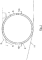
- Fig. 1 is a sectional view of an inventively arranged pressure tank 1, cut normal to the axial direction of the pressure tank 1, shown.
- the pressure tank 1 is carried in a support member 2, which forms a half shell on the underside of the pressure tank 1, so that the support member 2 surrounds the underside of the pressure tank 1.
- the support element 2 is fixedly connected to a body 3 by means of a connection to the body 10, so that the support element 2 can contribute to increasing the rigidity of the body 3.
- the support element 2 forms a portion of the underrun protection of the motor vehicle and therefore extends to a ground clearance line 11.
- An upper half-shell 5 partially surrounds the upper side of the pressure tank 1, the upper half-shell 5 also following the contour of the pressure tank 1 normal to the axial direction in the illustrated plane.
- the upper half-shell 5 is attached to the body 3 of the motor vehicle.
- a rubber band is arranged radially as a resilient layer 6.
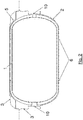
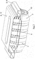
- Fig. 2 is a representation showing the arrangement according to Fig. 1 parallel to the axial direction of the pressure tank. As can be seen in this illustration, a plurality of rubber bands or elastic layers 6 are arranged distributed along the longitudinal axis of the pressure tank 1.
- the support element 2 follows the contour of the pressure tank 1 both radially and in the axial direction of the pressure tank.
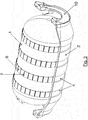
- Fig. 3 In this case, the body of the vehicle itself is not shown, but a semi-circular running connection to the body 10 at both axial ends of the support member 2, whereby this can attach to a body.
- the support element 2 has axially distributed a plurality of radially encircling beads 4.
- the beads 4 are arranged axially at the same positions at which the rubber bands of the elastic layer 6 are located.
- the rubber bands are arranged between the support element 2 and the pressure tank 1 and have along the circumference in each case many axially extending elevations 7.
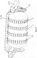
- the support member 2 is attached to the longitudinal members 9 of the body 3 via the two connections to the body 10. It is in Fig. 4 the support element 2 is not shown, in Fig. 6 and Fig. 7 the pressure tank 1 not shown.
- Fig. 5 represents a complete arrangement according to the invention, which in this case also includes an upper half-shell 5 for receiving the pressure tank 1.
- the upper half shell 5 is largely and the rear floor 12 partially adapted to the contour of the pressure tank 1.
- the rubber bands forming the elastic layer 6 are respectively disposed on the inner sides of the support member 2 and the upper half-shell 5 and thus between the half-shells and the pressure tank 1.
- Fig. 6 the pressure tank 1 is not shown and thereby the radially encircling rubber bands of the elastic layer 6 with their axially extending elevations 7 particularly clearly visible.
- Fig. 8, 9 and 10 represent a section of an elastic layer 6 from different angles.
- the elastic layer 6, for example, a rubber band, has a plurality of regularly distributed nubs 8, which protrude on the side facing the pressure tank from the elastic layer 6.
- the individual nubs 8 have a round cross section, other shapes, such as rectangular and square cross sections are also possible.
Description
Die vorliegende Erfindung betrifft ein Kraftfahrzeug aufweisend einen Drucktank und ein Tragelement, wobei das Tragelement den Drucktank trägt.The present invention relates to a motor vehicle comprising a pressure tank and a support element, wherein the support element carries the pressure tank.
Kraftfahrzeuge in welche Drucktanks eingebaut sind, sind inzwischen hinlänglich bekannt. Insbesondere verfügen mit Erdgas betriebene Fahrzeuge über Drucktanks in Form von CNG (compressed natural gas) Flaschen. Zur Befestigung solcher Drucktanks ist es bekannt einen Drucktank mittels Spannband an einer Blechschale zu fixieren. Eine derartige Anordnung kann beispielsweise in der Nähe eines Unterbodenschutzes eines Fahrzeuges angebracht sein.Motor vehicles in which pressure tanks are installed, are now well known. In particular, natural gas vehicles have pressure tanks in the form of CNG (compressed natural gas) cylinders. To attach such pressure tanks, it is known to fix a pressure tank by means of clamping band on a sheet metal shell. Such an arrangement may, for example, be mounted in the vicinity of an underbody protection of a vehicle.
So offenbart zum Beispiel die
Die
Es ist eine Aufgabe der Erfindung, ein Kraftfahrzeug aufweisend einen Drucktank und ein Tragelement anzugeben, wobei der Drucktank und dessen Tragelement nur geringen Bauraum benötigen und das Kraftfahrzeug geringes Gewicht und hohe Steifigkeit aufweist und dennoch einfach und kostengünstig gebaut werden kann.It is an object of the invention to provide a motor vehicle having a pressure tank and a support element, wherein the pressure tank and its support element require only small space and the motor vehicle has low weight and high rigidity and yet can be easily and inexpensively built.
Die Lösung der Aufgabe erfolgt durch ein Kraftfahrzeug aufweisend einen Drucktank und ein Tragelement mit den weiteren Merkmalen gemäß Anspruch 1.The object is achieved by a motor vehicle having a pressure tank and a support element with the further features according to
Erfindungsgemäß ist das Tragelement für den Drucktank als Halbschale ausgebildet die den Drucktank an dessen Unterseite trägt, wobei das Tragelement der Kontur des Drucktanks folgt, das heißt, dass die Form des Tragelements der Form des Drucktanks abschnittsweise entspricht, insbesondere für einen zylindrischen Drucktank das Tragelement über einen Teil der Länge des Drucktanks dem Radius des Drucktanks folgt. Hierdurch kann das Tragelement besonders eng am Drucktank anliegen und benötigt nur wenig Bauraum. Dazu erfüllt die Halbschale einen Doppelnutzen, da zusätzlich zur Tragefunktion der Halbschale diese auch zur Versteifung der Karosserie des Kraftfahrzeugs genutzt wird. Hierzu ist das Tragelement so stabil ausgeführt und so fest mit der Karosserie verbunden, dass durch das Tragelement eine Strukturversteifung, insbesondere eine torsionssteifere Karosserie erreicht wird. Durch diese Maßnahme kann gegebenenfalls ein eigenes Karosseriebauteil eingespart werden oder andere Karosserieteile weniger stark dimensioniert werden, so dass eine zusätzliche Einsparung von Bauraum, Gewicht und Kosten erzielt wird.According to the invention, the support element for the pressure tank is formed as a half-shell which carries the pressure tank on its underside, wherein the support element follows the contour of the pressure tank, that is, that the shape of the support element of the shape of the pressure tank partially corresponds, in particular for a cylindrical pressure tank, the support element over a part of the length of the pressure tank follows the radius of the pressure tank. As a result, the support element can rest particularly closely on the pressure tank and requires only little installation space. For this purpose, the half-shell meets a double benefit, since in addition to the carrying function of the half-shell, this is also used to stiffen the body of the motor vehicle. For this purpose, the support element is carried out so stable and so firmly connected to the body that a structural reinforcement, in particular a torsionally rigid body is achieved by the support member. By this measure, if necessary, a separate body component can be saved or other body parts are dimensioned less strong, so that an additional saving of space, weight and cost is achieved.
Erfindungsgemäß ist zwischen dem Tragelement und dem Drucktank eine elastische Lage angeordnet, wobei die elastische Lage durch ein über den gesamten Umfang des Drucktanks verlaufendes Band gebildet wird. Die elastische Lage kann den Drucktank in Position halten.According to the invention, an elastic layer is arranged between the support element and the pressure tank, wherein the elastic layer is formed by a running over the entire circumference of the pressure tank band. The elastic layer can hold the pressure tank in position.
Weiterbildungen der Erfindung sind in den abhängigen Ansprüchen, der Beschreibung sowie den beigefügten Zeichnungen angegeben.Further developments of the invention are specified in the dependent claims, the description and the accompanying drawings.
Vorzugsweise ist der Drucktank zylindrisch ausgebildet.Preferably, the pressure tank is cylindrical.
Der Drucktank kann auch durch mehrere einzelne, beispielsweise zylindrische Tanks gebildet werden, die von einem gemeinsamen Tragelement getragen werden. Das Tragelement kann dann der Kontur des gesamten Drucktanks folgen, so dass die Konturanpassung sich großteils oder ausschließlich auf die äußeren Tanks bezieht, die die Enden des Drucktanks bilden.The pressure tank can also be formed by a plurality of individual, for example, cylindrical tanks, which are supported by a common support element. The support member may then follow the contour of the entire pressure tank so that the contour adjustment relates largely or exclusively to the outer tanks forming the ends of the pressure tank.
Das Tragelement folgt der Kontur des Drucktanks bevorzugt im Wesentlichen über die ganze axiale Länge des Drucktanks, insbesondere wird der Drucktank hierdurch über seine ganze Länge an dessen Unterseite von der Halbschale überdeckt. Radial umgibt die Halbschale den Drucktank nicht vollumfänglich sondern folgt dessen Kontur in einem unteren Bereich des Drucktanks.The support element preferably follows the contour of the pressure tank essentially over the entire axial length of the pressure tank; in particular, the pressure tank is thereby covered over its entire length on its underside by the half shell. Radially, the half-shell does not completely surround the pressure tank but follows its contour in a lower area of the pressure tank.
Das Tragelement kann als Blech ausgebildet sein, insbesondere als Stahlblech.The support member may be formed as a sheet, in particular as a steel sheet.
Am Tragelement können bevorzugt Sicken ausgebildet sein, um das Bauteil steifer zu gestalten. In Hohlräumen zwischen den Sicken kann sich auch Wasser bzw. Kondensat sammeln und über bevorzugt ausgebildete Löcher an tiefsten Punkten der Halbschale abfließen.On the support element beads may preferably be formed to make the component stiffer. In cavities between the beads can be also collect water or condensate and drain through preferably formed holes at the lowest points of the half-shell.
Bevorzugt bildet das Tragelement einen Abschnitt des Unterfahrschutzes des Kraftfahrzeugs. Somit übernimmt das Tragelement zusätzlich die Funktion eines Unterfahrschutzes bzw. Unterbodens des Fahrzeuges. Das Tragelement kann auch als Wärmeabschirmblech, CW-Verkleidung und/oder als Schubfeld eingesetzt werden, so dass entsprechende sonst erforderliche Bauteile entfallen können.Preferably, the support member forms a portion of the underrun protection of the motor vehicle. Thus, the support element additionally assumes the function of an underrun protection or underbody of the vehicle. The support element can also be used as a heat shield, CW panel and / or push panel, so that corresponding otherwise required components can be omitted.
In einer bevorzugten Ausführungsform weist das Kraftfahrzeug auch eine obere Halbschale auf, so dass die obere Halbschale die Oberseite des Drucktanks zumindest teilweise umgibt, wobei die obere Halbschale der Kontur des Drucktanks folgt. Auch die obere Halbschale ist besonders bevorzugt an der Karosserie des Kraftfahrzeugs befestigt. Hierdurch kann der Drucktank besonders stabil gehalten werden und eine zusätzliche Versteifung der Karosserie erreicht werden.In a preferred embodiment, the motor vehicle also has an upper half shell, so that the upper half shell at least partially surrounds the upper side of the pressure tank, with the upper half shell following the contour of the pressure tank. Also, the upper half-shell is particularly preferably attached to the body of the motor vehicle. As a result, the pressure tank can be kept very stable and an additional stiffening of the body can be achieved.
Um radiale und axiale Längenänderungen des Drucktanks gut aufnehmen zu können weist die elastische Lage besonders bevorzugt radial verteilte axial verlaufende Erhebungen auf oder Noppen.In order to accommodate radial and axial changes in length of the pressure tank well, the elastic layer particularly preferably radially distributed axially extending elevations or nubs.
Die elastische Lage kann durch ein über den gesamten Umfang des Drucktanks verlaufendes elastisches Band, insbesondere Gummiband, gebildet werden. Über die Länge des Drucktanks können mehrere derartige umfänglich verlaufende Bänder angeordnet sein.The elastic layer can be formed by a running over the entire circumference of the pressure tank elastic band, in particular rubber band. Over the length of the pressure tank, a plurality of such circumferentially extending bands may be arranged.
Bevorzugt ist das Tragelement an einem linken und/oder rechten Längsträger befestigt, insbesondere verschraubt.Preferably, the support element is attached to a left and / or right side member, in particular screwed.
Der Drucktank ist bevorzugt quer zur Fahrtrichtung angeordnet, insbesondere im Heck bzw. Hinterwagen des Kraftfahrzeuges.The pressure tank is preferably arranged transversely to the direction of travel, in particular in the rear or rear of the motor vehicle.
Die Erfindung wird im Folgenden beispielhaft unter Bezugnahme auf die Zeichnungen beschrieben.
- Fig. 1
- ist eine teilweise Schnittansicht eines erfindungsgemäßen Kraftfahrzeugs, umfassend einen Drucktank und ein Tragelement, geschnitten normal zur Achsrichtung des Drucktanks.
- Fig. 2
- ist eine Darstellung, welche die Anordnung gemäß
Fig. 1 geschnitten parallel zur Achsrichtung des Drucktanks zeigt. - Fig. 3
- ist eine dreidimensionale Ansicht eines erfindungsgemäßen Kraftfahrzeugs, umfassend einen Drucktank und ein Tragelement.
- Fig. 4
- ist eine dreidimensionale Ansicht der Anordnung gemäß
Fig. 3 , jedoch ohne Tragelement aber mit Teilen der Karosserie. - Fig. 5
- ist eine dreidimensionale Ansicht der Anordnung gemäß
Fig. 4 , jedoch mit Tragelement und mit einer oberen Halbschale. - Fig. 6
- ist eine dreidimensionale Ansicht des Tragelements ohne Drucktank.
- Fig. 7
- ist eine dreidimensionale Ansicht der Anordnung gemäß
Fig. 6 , jedoch mit Heckboden. - Fig. 8
- ist eine ausschnittsweise dreidimensionale Ansicht eines Gummibandes auf der vom Drucktank abgewandten Seite.
- Fig. 9
- ist eine ausschnittsweise dreidimensionale Ansicht eines Gummibandes auf der dem Drucktank zugewandten Seite.
- Fig. 10
- ist eine ausschnittsweise dreidimensionale Ansicht eines Gummibandes von der Seite.
- Fig. 1
- is a partial sectional view of a motor vehicle according to the invention, comprising a pressure tank and a support member, cut normal to the axial direction of the pressure tank.
- Fig. 2
- is a representation showing the arrangement according to
Fig. 1 cut parallel to the axial direction of the pressure tank shows. - Fig. 3
- is a three-dimensional view of a motor vehicle according to the invention, comprising a pressure tank and a support element.
- Fig. 4
- is a three-dimensional view of the arrangement according to
Fig. 3 , but without support element but with parts of the body. - Fig. 5
- is a three-dimensional view of the arrangement according to
Fig. 4 , but with support element and with an upper half-shell. - Fig. 6
- is a three-dimensional view of the support element without a pressure tank.
- Fig. 7
- is a three-dimensional view of the arrangement according to
Fig. 6 , but with rear floor. - Fig. 8
- is a fragmentary three-dimensional view of a rubber band on the side facing away from the pressure tank side.
- Fig. 9
- is a fragmentary three-dimensional view of a rubber band on the pressure tank side facing.
- Fig. 10
- is a partial three-dimensional view of a rubber band from the side.
In
Das Tragelement 2 bildet einen Abschnitt des Unterfahrschutzes des Kraftfahrzeugs und reicht daher bis zu einer Bodenfreiheitslinie 11.The
Eine obere Halbschale 5 umgibt die Oberseite des Drucktanks 1 teilweise, wobei auch die obere Halbschale 5 in der dargestellten Ebene normal zur Achsrichtung der Kontur des Drucktanks 1 folgt.An upper half-
Auch die obere Halbschale 5 ist an der Karosserie 3 des Kraftfahrzeugs befestigt.Also, the upper half-
Zwischen dem Tragelement 2 und dem Drucktank 1 ist radial umlaufend ein Gummiband als elastische Lage 6 angeordnet.Between the
In dieser Ausführungsform folgt das Tragelement 2 der Kontur des Drucktanks 1 sowohl radial als auch in Achsrichtung des Drucktanks.In this embodiment, the
Das Tragelement 2 weist axial verteilt mehrere radial umlaufende Sicken 4 auf. Die Sicken 4 sind axial an den selben Positionen angeordnet an welchen sich auch die Gummibänder der elastischen Lage 6 befinden.The
Die Gummibänder sind zwischen Tragelement 2 und Drucktank 1 angeordnet und weisen entlang des Umfangs jeweils viele axial verlaufende Erhebungen 7 auf.The rubber bands are arranged between the
Wie in den
In
- 11
- Drucktankpressure tank
- 22
- Tragelementsupporting member
- 33
- Karosseriebody
- 44
- SickeBeading
- 55
- obere Halbschaleupper half shell
- 66
- elastische Lageelastic situation
- 77
- axial verlaufende Erhebungaxially extending survey
- 88th
- Noppeburl
- 99
- Längsträgerlongitudinal beams
- 1010
- Anbindung zur KarosserieConnection to the body
- 1111
- BodenfreiheitslinieGround clearance line
- 1212
- Heckbodenrear floor
Claims (12)
- Motor vehicle having a pressurised tank (1) and a supporting element (2), the supporting element (2) supporting the pressurised tank (1), the supporting element (2) being configured as a lower half shell, with the result that the supporting element (2) at least partially surrounds the underside of the pressurised tank (1), the supporting element (2) substantially following the contour of the pressurised tank (1), the supporting element (2) being fastened to the body (3) of the motor vehicle, with the result that the body (3) is reinforced by way of the supporting element (2), characterized in that an elastic layer (6) is arranged between the supporting element (2) and the pressurised tank (1), the elastic layer (6) being formed by way of a strip which runs over the entire circumference of the pressurised tank (1).
- Motor vehicle according to Claim 1, characterized in that the pressurised tank (1) is cylindrical.
- Motor vehicle according to Claim 1 or 2, characterized in that the supporting element (2) follows the contour of the pressurised tank (1) substantially over the entire length of the pressurised tank (1).
- Motor vehicle according to at least one of the preceding claims, characterized in that the supporting element (2) is configured as a metal sheet.
- Motor vehicle according to at least one of the preceding claims, characterized in that beads (4) are configured on the supporting element (2).
- Motor vehicle according to at least one of the preceding claims, characterized in that the supporting element (2) forms a section of the underride guard of the motor vehicle.
- Motor vehicle according to at least one of the preceding claims, characterized in that it has an upper half shell (5), with the result that the upper half shell (5) at least partially surrounds the upper side of the pressurised tank (1), the upper half shell (5) following the contour of the pressurised tank (1).
- Motor vehicle according to Claim 7, characterized in that the upper half shell (5) is fastened to the body (3) of the motor vehicle.
- Motor vehicle according to Claim 1, characterized in that the elastic layer (6) has axially running elevations (7) or bumps (8).
- Motor vehicle according to Claim 1 or 9, characterized in that the elastic layer (6) is formed by way of a rubber strip which runs over the entire circumference of the pressurised tank (1).
- Motor vehicle according to at least one of the preceding claims, characterized in that the supporting element (2) is fastened, in particular screwed, to a left-hand and/or right-hand longitudinal carrier (9).
- Motor vehicle according to at least one of the preceding claims, characterized in that the pressurised tank (1) is arranged transversely with respect to the driving direction, in particular in the rear of the motor vehicle.
Priority Applications (1)
| Application Number | Priority Date | Filing Date | Title |
|---|---|---|---|
| EP14172207.4A EP2915687B1 (en) | 2014-03-07 | 2014-06-12 | Motor vehicle with pressurised tank and supporting element |
Applications Claiming Priority (2)
| Application Number | Priority Date | Filing Date | Title |
|---|---|---|---|
| EP14158418 | 2014-03-07 | ||
| EP14172207.4A EP2915687B1 (en) | 2014-03-07 | 2014-06-12 | Motor vehicle with pressurised tank and supporting element |
Publications (2)
| Publication Number | Publication Date |
|---|---|
| EP2915687A1 EP2915687A1 (en) | 2015-09-09 |
| EP2915687B1 true EP2915687B1 (en) | 2017-08-09 |
Family
ID=50236066
Family Applications (1)
| Application Number | Title | Priority Date | Filing Date |
|---|---|---|---|
| EP14172207.4A Active EP2915687B1 (en) | 2014-03-07 | 2014-06-12 | Motor vehicle with pressurised tank and supporting element |
Country Status (1)
| Country | Link |
|---|---|
| EP (1) | EP2915687B1 (en) |
Families Citing this family (5)
| Publication number | Priority date | Publication date | Assignee | Title |
|---|---|---|---|---|
| WO2017205279A1 (en) | 2016-05-21 | 2017-11-30 | Worthington Industries, Inc. | Methods and systems for alternative fuel container support |
| DE102017206127A1 (en) * | 2017-04-10 | 2018-10-11 | Bayerische Motoren Werke Aktiengesellschaft | Motor vehicle with a fuel pressure tank |
| EP3415355B1 (en) * | 2017-06-13 | 2020-05-06 | FCA Italy S.p.A. | A system for supporting and protecting a gas tank of a gas fuel system on-board of a motor-vehicle |
| JP6809411B2 (en) * | 2017-08-09 | 2021-01-06 | トヨタ自動車株式会社 | Vehicle undercarriage |
| DE102017129526A1 (en) | 2017-12-12 | 2019-06-13 | Deutsches Zentrum für Luft- und Raumfahrt e.V. | Tank device, vehicle and method for producing a tank device |
Family Cites Families (10)
| Publication number | Priority date | Publication date | Assignee | Title |
|---|---|---|---|---|
| JP3205255B2 (en) * | 1996-05-09 | 2001-09-04 | 本田技研工業株式会社 | Vehicle fuel cylinder mounting structure |
| MY125923A (en) * | 1998-10-27 | 2006-08-30 | Univ Johns Hopkins | Compressed gas fuel storage system |
| JP4690666B2 (en) * | 2004-06-25 | 2011-06-01 | 本田技研工業株式会社 | Anti-vibration support structure for vehicle fuel tank |
| US7270209B2 (en) | 2004-08-10 | 2007-09-18 | General Motors Corporation | Modular fuel storage system for a vehicle |
| US20060061081A1 (en) * | 2004-09-10 | 2006-03-23 | Kresse Alfred L Jr | Compressed gas tank carrier assembly |
| JP4648009B2 (en) * | 2005-01-11 | 2011-03-09 | 山下ゴム株式会社 | Anti-vibration support structure for vehicle parts |
| US20070045328A1 (en) * | 2005-08-30 | 2007-03-01 | Smith Jeffrey C | Protecto plate |
| CN101734149A (en) * | 2009-12-28 | 2010-06-16 | 力帆实业(集团)股份有限公司 | Mounting structure of gas cylinders of passenger car |
| CN201777124U (en) * | 2010-08-12 | 2011-03-30 | 上海汽车工业(集团)总公司 | Hydrogen bottle protecting cover |
| KR101315705B1 (en) * | 2010-12-14 | 2013-10-10 | 김학성 | Sensing apparatus for gas case |
-
2014
- 2014-06-12 EP EP14172207.4A patent/EP2915687B1/en active Active
Non-Patent Citations (1)
| Title |
|---|
| None * |
Also Published As
| Publication number | Publication date |
|---|---|
| EP2915687A1 (en) | 2015-09-09 |
Similar Documents
| Publication | Publication Date | Title |
|---|---|---|
| EP2915687B1 (en) | Motor vehicle with pressurised tank and supporting element | |
| EP0245612B1 (en) | Steering column attachment in a vehicle | |
| EP1970260B1 (en) | Crashbox and motor vehicle bumper arrangement | |
| DE102007024628B4 (en) | Wheel suspension device and suspension strut | |
| DE112008002821T5 (en) | Vehicle equipped with high pressure tank, and tank arrangement | |
| DE102007035482A1 (en) | Switchgear assembly for a motor vehicle | |
| DE102009012057A1 (en) | Device for picking up lateral forces | |
| DE102017011343B4 (en) | washer fluid reservoir | |
| EP0780283B1 (en) | Vehicle body assembly | |
| EP1304281A2 (en) | Vehicle with a reinforcing insert in the sill beam | |
| DE102017011492A1 (en) | Load-bearing pressure tank for storing fuel and motor vehicle | |
| DE102011014334A1 (en) | Attachment structure for arranging gas tank in bottom portion of vehicle, has tank holders with fastening bands, fastening portions that are directly mounted on vehicle, and fastening regions with supporting foot mounted on vehicle | |
| DE102017011968B4 (en) | Device for protecting battery modules in a motor vehicle | |
| DE2553822C2 (en) | ||
| DE102010013840A1 (en) | Vehicle body with a longitudinal member and an elastomer bearing arranged thereon, in particular as a gearbox bearing | |
| DE102008063448B4 (en) | Vehicle body | |
| DE102014009052A1 (en) | Cab resistant exhaust pipe for one vehicle | |
| EP2983930B1 (en) | Structural element in the front region of a motor vehicle | |
| EP2520822A2 (en) | Spring pocket with a support spring | |
| EP3339106B1 (en) | Rear underride guard for a vehicle | |
| DE102015011707B4 (en) | Suspension component for a motor vehicle | |
| WO2018100038A1 (en) | Steering wheel skeleton and vehicle steering wheel having such a steering wheel skeleton | |
| DE102017221351A1 (en) | Subframe of a motor vehicle | |
| DE102012015334A1 (en) | Fastening arrangement for fastening stiffening brace to structural support e.g. windscreen cross section of passenger car, fixed stiffening braces to structural support through outstanding tab portion in hollow cross-section | |
| DE102019108026A1 (en) | Federbeinjoch |
Legal Events
| Date | Code | Title | Description |
|---|---|---|---|
| PUAI | Public reference made under article 153(3) epc to a published international application that has entered the european phase |
Free format text: ORIGINAL CODE: 0009012 |
|
| AK | Designated contracting states |
Kind code of ref document: A1 Designated state(s): AL AT BE BG CH CY CZ DE DK EE ES FI FR GB GR HR HU IE IS IT LI LT LU LV MC MK MT NL NO PL PT RO RS SE SI SK SM TR |
|
| AX | Request for extension of the european patent |
Extension state: BA ME |
|
| 17P | Request for examination filed |
Effective date: 20160120 |
|
| RBV | Designated contracting states (corrected) |
Designated state(s): AL AT BE BG CH CY CZ DE DK EE ES FI FR GB GR HR HU IE IS IT LI LT LU LV MC MK MT NL NO PL PT RO RS SE SI SK SM TR |
|
| 17Q | First examination report despatched |
Effective date: 20160803 |
|
| REG | Reference to a national code |
Ref country code: DE Ref legal event code: R079 Ref document number: 502014004884 Country of ref document: DE Free format text: PREVIOUS MAIN CLASS: B60K0015070000 Ipc: B60K0015063000 |
|
| GRAP | Despatch of communication of intention to grant a patent |
Free format text: ORIGINAL CODE: EPIDOSNIGR1 |
|
| RIC1 | Information provided on ipc code assigned before grant |
Ipc: B60K 15/03 20060101ALI20170222BHEP Ipc: B60K 15/07 20060101ALI20170222BHEP Ipc: B60K 15/063 20060101AFI20170222BHEP |
|
| INTG | Intention to grant announced |
Effective date: 20170328 |
|
| GRAS | Grant fee paid |
Free format text: ORIGINAL CODE: EPIDOSNIGR3 |
|
| GRAA | (expected) grant |
Free format text: ORIGINAL CODE: 0009210 |
|
| AK | Designated contracting states |
Kind code of ref document: B1 Designated state(s): AL AT BE BG CH CY CZ DE DK EE ES FI FR GB GR HR HU IE IS IT LI LT LU LV MC MK MT NL NO PL PT RO RS SE SI SK SM TR |
|
| REG | Reference to a national code |
Ref country code: GB Ref legal event code: FG4D Free format text: NOT ENGLISH |
|
| REG | Reference to a national code |
Ref country code: CH Ref legal event code: EP Ref country code: AT Ref legal event code: REF Ref document number: 916413 Country of ref document: AT Kind code of ref document: T Effective date: 20170815 |
|
| REG | Reference to a national code |
Ref country code: IE Ref legal event code: FG4D Free format text: LANGUAGE OF EP DOCUMENT: GERMAN |
|
| REG | Reference to a national code |
Ref country code: DE Ref legal event code: R096 Ref document number: 502014004884 Country of ref document: DE |
|
| REG | Reference to a national code |
Ref country code: NL Ref legal event code: MP Effective date: 20170809 |
|
| REG | Reference to a national code |
Ref country code: LT Ref legal event code: MG4D |
|
| PG25 | Lapsed in a contracting state [announced via postgrant information from national office to epo] |
Ref country code: FI Free format text: LAPSE BECAUSE OF FAILURE TO SUBMIT A TRANSLATION OF THE DESCRIPTION OR TO PAY THE FEE WITHIN THE PRESCRIBED TIME-LIMIT Effective date: 20170809 Ref country code: NO Free format text: LAPSE BECAUSE OF FAILURE TO SUBMIT A TRANSLATION OF THE DESCRIPTION OR TO PAY THE FEE WITHIN THE PRESCRIBED TIME-LIMIT Effective date: 20171109 Ref country code: LT Free format text: LAPSE BECAUSE OF FAILURE TO SUBMIT A TRANSLATION OF THE DESCRIPTION OR TO PAY THE FEE WITHIN THE PRESCRIBED TIME-LIMIT Effective date: 20170809 Ref country code: HR Free format text: LAPSE BECAUSE OF FAILURE TO SUBMIT A TRANSLATION OF THE DESCRIPTION OR TO PAY THE FEE WITHIN THE PRESCRIBED TIME-LIMIT Effective date: 20170809 Ref country code: NL Free format text: LAPSE BECAUSE OF FAILURE TO SUBMIT A TRANSLATION OF THE DESCRIPTION OR TO PAY THE FEE WITHIN THE PRESCRIBED TIME-LIMIT Effective date: 20170809 Ref country code: SE Free format text: LAPSE BECAUSE OF FAILURE TO SUBMIT A TRANSLATION OF THE DESCRIPTION OR TO PAY THE FEE WITHIN THE PRESCRIBED TIME-LIMIT Effective date: 20170809 |
|
| PG25 | Lapsed in a contracting state [announced via postgrant information from national office to epo] |
Ref country code: PL Free format text: LAPSE BECAUSE OF FAILURE TO SUBMIT A TRANSLATION OF THE DESCRIPTION OR TO PAY THE FEE WITHIN THE PRESCRIBED TIME-LIMIT Effective date: 20170809 Ref country code: GR Free format text: LAPSE BECAUSE OF FAILURE TO SUBMIT A TRANSLATION OF THE DESCRIPTION OR TO PAY THE FEE WITHIN THE PRESCRIBED TIME-LIMIT Effective date: 20171110 Ref country code: IS Free format text: LAPSE BECAUSE OF FAILURE TO SUBMIT A TRANSLATION OF THE DESCRIPTION OR TO PAY THE FEE WITHIN THE PRESCRIBED TIME-LIMIT Effective date: 20171209 Ref country code: LV Free format text: LAPSE BECAUSE OF FAILURE TO SUBMIT A TRANSLATION OF THE DESCRIPTION OR TO PAY THE FEE WITHIN THE PRESCRIBED TIME-LIMIT Effective date: 20170809 Ref country code: RS Free format text: LAPSE BECAUSE OF FAILURE TO SUBMIT A TRANSLATION OF THE DESCRIPTION OR TO PAY THE FEE WITHIN THE PRESCRIBED TIME-LIMIT Effective date: 20170809 Ref country code: BG Free format text: LAPSE BECAUSE OF FAILURE TO SUBMIT A TRANSLATION OF THE DESCRIPTION OR TO PAY THE FEE WITHIN THE PRESCRIBED TIME-LIMIT Effective date: 20171109 Ref country code: ES Free format text: LAPSE BECAUSE OF FAILURE TO SUBMIT A TRANSLATION OF THE DESCRIPTION OR TO PAY THE FEE WITHIN THE PRESCRIBED TIME-LIMIT Effective date: 20170809 |
|
| PG25 | Lapsed in a contracting state [announced via postgrant information from national office to epo] |
Ref country code: CZ Free format text: LAPSE BECAUSE OF FAILURE TO SUBMIT A TRANSLATION OF THE DESCRIPTION OR TO PAY THE FEE WITHIN THE PRESCRIBED TIME-LIMIT Effective date: 20170809 Ref country code: RO Free format text: LAPSE BECAUSE OF FAILURE TO SUBMIT A TRANSLATION OF THE DESCRIPTION OR TO PAY THE FEE WITHIN THE PRESCRIBED TIME-LIMIT Effective date: 20170809 Ref country code: DK Free format text: LAPSE BECAUSE OF FAILURE TO SUBMIT A TRANSLATION OF THE DESCRIPTION OR TO PAY THE FEE WITHIN THE PRESCRIBED TIME-LIMIT Effective date: 20170809 |
|
| REG | Reference to a national code |
Ref country code: DE Ref legal event code: R097 Ref document number: 502014004884 Country of ref document: DE |
|
| PG25 | Lapsed in a contracting state [announced via postgrant information from national office to epo] |
Ref country code: SK Free format text: LAPSE BECAUSE OF FAILURE TO SUBMIT A TRANSLATION OF THE DESCRIPTION OR TO PAY THE FEE WITHIN THE PRESCRIBED TIME-LIMIT Effective date: 20170809 Ref country code: EE Free format text: LAPSE BECAUSE OF FAILURE TO SUBMIT A TRANSLATION OF THE DESCRIPTION OR TO PAY THE FEE WITHIN THE PRESCRIBED TIME-LIMIT Effective date: 20170809 Ref country code: SM Free format text: LAPSE BECAUSE OF FAILURE TO SUBMIT A TRANSLATION OF THE DESCRIPTION OR TO PAY THE FEE WITHIN THE PRESCRIBED TIME-LIMIT Effective date: 20170809 |
|
| PLBE | No opposition filed within time limit |
Free format text: ORIGINAL CODE: 0009261 |
|
| STAA | Information on the status of an ep patent application or granted ep patent |
Free format text: STATUS: NO OPPOSITION FILED WITHIN TIME LIMIT |
|
| REG | Reference to a national code |
Ref country code: FR Ref legal event code: PLFP Year of fee payment: 5 |
|
| 26N | No opposition filed |
Effective date: 20180511 |
|
| PG25 | Lapsed in a contracting state [announced via postgrant information from national office to epo] |
Ref country code: SI Free format text: LAPSE BECAUSE OF FAILURE TO SUBMIT A TRANSLATION OF THE DESCRIPTION OR TO PAY THE FEE WITHIN THE PRESCRIBED TIME-LIMIT Effective date: 20170809 |
|
| PG25 | Lapsed in a contracting state [announced via postgrant information from national office to epo] |
Ref country code: MT Free format text: LAPSE BECAUSE OF FAILURE TO SUBMIT A TRANSLATION OF THE DESCRIPTION OR TO PAY THE FEE WITHIN THE PRESCRIBED TIME-LIMIT Effective date: 20170809 |
|
| REG | Reference to a national code |
Ref country code: CH Ref legal event code: PL |
|
| REG | Reference to a national code |
Ref country code: BE Ref legal event code: MM Effective date: 20180630 |
|
| REG | Reference to a national code |
Ref country code: IE Ref legal event code: MM4A |
|
| PG25 | Lapsed in a contracting state [announced via postgrant information from national office to epo] |
Ref country code: LU Free format text: LAPSE BECAUSE OF NON-PAYMENT OF DUE FEES Effective date: 20180612 Ref country code: MC Free format text: LAPSE BECAUSE OF FAILURE TO SUBMIT A TRANSLATION OF THE DESCRIPTION OR TO PAY THE FEE WITHIN THE PRESCRIBED TIME-LIMIT Effective date: 20170809 |
|
| PG25 | Lapsed in a contracting state [announced via postgrant information from national office to epo] |
Ref country code: IE Free format text: LAPSE BECAUSE OF NON-PAYMENT OF DUE FEES Effective date: 20180612 Ref country code: LI Free format text: LAPSE BECAUSE OF NON-PAYMENT OF DUE FEES Effective date: 20180630 Ref country code: CH Free format text: LAPSE BECAUSE OF NON-PAYMENT OF DUE FEES Effective date: 20180630 |
|
| PG25 | Lapsed in a contracting state [announced via postgrant information from national office to epo] |
Ref country code: BE Free format text: LAPSE BECAUSE OF NON-PAYMENT OF DUE FEES Effective date: 20180630 |
|
| PGFP | Annual fee paid to national office [announced via postgrant information from national office to epo] |
Ref country code: IT Payment date: 20190624 Year of fee payment: 6 |
|
| PGFP | Annual fee paid to national office [announced via postgrant information from national office to epo] |
Ref country code: FR Payment date: 20190619 Year of fee payment: 6 |
|
| PGFP | Annual fee paid to national office [announced via postgrant information from national office to epo] |
Ref country code: GB Payment date: 20190619 Year of fee payment: 6 |
|
| PG25 | Lapsed in a contracting state [announced via postgrant information from national office to epo] |
Ref country code: TR Free format text: LAPSE BECAUSE OF FAILURE TO SUBMIT A TRANSLATION OF THE DESCRIPTION OR TO PAY THE FEE WITHIN THE PRESCRIBED TIME-LIMIT Effective date: 20170809 |
|
| PG25 | Lapsed in a contracting state [announced via postgrant information from national office to epo] |
Ref country code: PT Free format text: LAPSE BECAUSE OF FAILURE TO SUBMIT A TRANSLATION OF THE DESCRIPTION OR TO PAY THE FEE WITHIN THE PRESCRIBED TIME-LIMIT Effective date: 20170809 |
|
| PG25 | Lapsed in a contracting state [announced via postgrant information from national office to epo] |
Ref country code: CY Free format text: LAPSE BECAUSE OF FAILURE TO SUBMIT A TRANSLATION OF THE DESCRIPTION OR TO PAY THE FEE WITHIN THE PRESCRIBED TIME-LIMIT Effective date: 20170809 Ref country code: HU Free format text: LAPSE BECAUSE OF FAILURE TO SUBMIT A TRANSLATION OF THE DESCRIPTION OR TO PAY THE FEE WITHIN THE PRESCRIBED TIME-LIMIT; INVALID AB INITIO Effective date: 20140612 Ref country code: MK Free format text: LAPSE BECAUSE OF NON-PAYMENT OF DUE FEES Effective date: 20170809 |
|
| PG25 | Lapsed in a contracting state [announced via postgrant information from national office to epo] |
Ref country code: AL Free format text: LAPSE BECAUSE OF FAILURE TO SUBMIT A TRANSLATION OF THE DESCRIPTION OR TO PAY THE FEE WITHIN THE PRESCRIBED TIME-LIMIT Effective date: 20170809 |
|
| REG | Reference to a national code |
Ref country code: AT Ref legal event code: MM01 Ref document number: 916413 Country of ref document: AT Kind code of ref document: T Effective date: 20190612 |
|
| PG25 | Lapsed in a contracting state [announced via postgrant information from national office to epo] |
Ref country code: AT Free format text: LAPSE BECAUSE OF NON-PAYMENT OF DUE FEES Effective date: 20190612 |
|
| GBPC | Gb: european patent ceased through non-payment of renewal fee |
Effective date: 20200612 |
|
| PG25 | Lapsed in a contracting state [announced via postgrant information from national office to epo] |
Ref country code: FR Free format text: LAPSE BECAUSE OF NON-PAYMENT OF DUE FEES Effective date: 20200630 Ref country code: GB Free format text: LAPSE BECAUSE OF NON-PAYMENT OF DUE FEES Effective date: 20200612 |
|
| PG25 | Lapsed in a contracting state [announced via postgrant information from national office to epo] |
Ref country code: IT Free format text: LAPSE BECAUSE OF NON-PAYMENT OF DUE FEES Effective date: 20200612 |
|
| PGFP | Annual fee paid to national office [announced via postgrant information from national office to epo] |
Ref country code: DE Payment date: 20230620 Year of fee payment: 10 |