EP2915684A1 - Pneumatic tire - Google Patents
Pneumatic tire Download PDFInfo
- Publication number
- EP2915684A1 EP2915684A1 EP14761170.1A EP14761170A EP2915684A1 EP 2915684 A1 EP2915684 A1 EP 2915684A1 EP 14761170 A EP14761170 A EP 14761170A EP 2915684 A1 EP2915684 A1 EP 2915684A1
- Authority
- EP
- European Patent Office
- Prior art keywords
- regions
- grooves
- shoulder
- groove
- lug
- Prior art date
- Legal status (The legal status is an assumption and is not a legal conclusion. Google has not performed a legal analysis and makes no representation as to the accuracy of the status listed.)
- Granted
Links
Images




Classifications
-
- B—PERFORMING OPERATIONS; TRANSPORTING
- B60—VEHICLES IN GENERAL
- B60C—VEHICLE TYRES; TYRE INFLATION; TYRE CHANGING; CONNECTING VALVES TO INFLATABLE ELASTIC BODIES IN GENERAL; DEVICES OR ARRANGEMENTS RELATED TO TYRES
- B60C11/00—Tyre tread bands; Tread patterns; Anti-skid inserts
- B60C11/03—Tread patterns
- B60C11/04—Tread patterns in which the raised area of the pattern consists only of continuous circumferential ribs, e.g. zig-zag
-
- B—PERFORMING OPERATIONS; TRANSPORTING
- B60—VEHICLES IN GENERAL
- B60C—VEHICLE TYRES; TYRE INFLATION; TYRE CHANGING; CONNECTING VALVES TO INFLATABLE ELASTIC BODIES IN GENERAL; DEVICES OR ARRANGEMENTS RELATED TO TYRES
- B60C11/00—Tyre tread bands; Tread patterns; Anti-skid inserts
- B60C11/03—Tread patterns
- B60C11/0304—Asymmetric patterns
-
- B—PERFORMING OPERATIONS; TRANSPORTING
- B60—VEHICLES IN GENERAL
- B60C—VEHICLE TYRES; TYRE INFLATION; TYRE CHANGING; CONNECTING VALVES TO INFLATABLE ELASTIC BODIES IN GENERAL; DEVICES OR ARRANGEMENTS RELATED TO TYRES
- B60C11/00—Tyre tread bands; Tread patterns; Anti-skid inserts
- B60C11/03—Tread patterns
- B60C11/0306—Patterns comprising block rows or discontinuous ribs
-
- B—PERFORMING OPERATIONS; TRANSPORTING
- B60—VEHICLES IN GENERAL
- B60C—VEHICLE TYRES; TYRE INFLATION; TYRE CHANGING; CONNECTING VALVES TO INFLATABLE ELASTIC BODIES IN GENERAL; DEVICES OR ARRANGEMENTS RELATED TO TYRES
- B60C11/00—Tyre tread bands; Tread patterns; Anti-skid inserts
- B60C11/03—Tread patterns
- B60C11/0306—Patterns comprising block rows or discontinuous ribs
- B60C11/0309—Patterns comprising block rows or discontinuous ribs further characterised by the groove cross-section
-
- B—PERFORMING OPERATIONS; TRANSPORTING
- B60—VEHICLES IN GENERAL
- B60C—VEHICLE TYRES; TYRE INFLATION; TYRE CHANGING; CONNECTING VALVES TO INFLATABLE ELASTIC BODIES IN GENERAL; DEVICES OR ARRANGEMENTS RELATED TO TYRES
- B60C11/00—Tyre tread bands; Tread patterns; Anti-skid inserts
- B60C11/03—Tread patterns
- B60C11/11—Tread patterns in which the raised area of the pattern consists only of isolated elements, e.g. blocks
-
- B—PERFORMING OPERATIONS; TRANSPORTING
- B60—VEHICLES IN GENERAL
- B60C—VEHICLE TYRES; TYRE INFLATION; TYRE CHANGING; CONNECTING VALVES TO INFLATABLE ELASTIC BODIES IN GENERAL; DEVICES OR ARRANGEMENTS RELATED TO TYRES
- B60C11/00—Tyre tread bands; Tread patterns; Anti-skid inserts
- B60C11/03—Tread patterns
- B60C11/12—Tread patterns characterised by the use of narrow slits or incisions, e.g. sipes
- B60C11/1204—Tread patterns characterised by the use of narrow slits or incisions, e.g. sipes with special shape of the sipe
- B60C11/1218—Three-dimensional shape with regard to depth and extending direction
-
- B—PERFORMING OPERATIONS; TRANSPORTING
- B60—VEHICLES IN GENERAL
- B60C—VEHICLE TYRES; TYRE INFLATION; TYRE CHANGING; CONNECTING VALVES TO INFLATABLE ELASTIC BODIES IN GENERAL; DEVICES OR ARRANGEMENTS RELATED TO TYRES
- B60C11/00—Tyre tread bands; Tread patterns; Anti-skid inserts
- B60C11/03—Tread patterns
- B60C11/12—Tread patterns characterised by the use of narrow slits or incisions, e.g. sipes
- B60C11/1259—Depth of the sipe
- B60C11/1263—Depth of the sipe different within the same sipe
-
- B—PERFORMING OPERATIONS; TRANSPORTING
- B60—VEHICLES IN GENERAL
- B60C—VEHICLE TYRES; TYRE INFLATION; TYRE CHANGING; CONNECTING VALVES TO INFLATABLE ELASTIC BODIES IN GENERAL; DEVICES OR ARRANGEMENTS RELATED TO TYRES
- B60C11/00—Tyre tread bands; Tread patterns; Anti-skid inserts
- B60C11/03—Tread patterns
- B60C11/13—Tread patterns characterised by the groove cross-section, e.g. for buttressing or preventing stone-trapping
- B60C11/1353—Tread patterns characterised by the groove cross-section, e.g. for buttressing or preventing stone-trapping with special features of the groove bottom
-
- B—PERFORMING OPERATIONS; TRANSPORTING
- B60—VEHICLES IN GENERAL
- B60C—VEHICLE TYRES; TYRE INFLATION; TYRE CHANGING; CONNECTING VALVES TO INFLATABLE ELASTIC BODIES IN GENERAL; DEVICES OR ARRANGEMENTS RELATED TO TYRES
- B60C11/00—Tyre tread bands; Tread patterns; Anti-skid inserts
- B60C11/03—Tread patterns
- B60C11/13—Tread patterns characterised by the groove cross-section, e.g. for buttressing or preventing stone-trapping
- B60C11/1369—Tie bars for linking block elements and bridging the groove
-
- B—PERFORMING OPERATIONS; TRANSPORTING
- B60—VEHICLES IN GENERAL
- B60C—VEHICLE TYRES; TYRE INFLATION; TYRE CHANGING; CONNECTING VALVES TO INFLATABLE ELASTIC BODIES IN GENERAL; DEVICES OR ARRANGEMENTS RELATED TO TYRES
- B60C11/00—Tyre tread bands; Tread patterns; Anti-skid inserts
- B60C11/03—Tread patterns
- B60C2011/0337—Tread patterns characterised by particular design features of the pattern
- B60C2011/0339—Grooves
- B60C2011/0341—Circumferential grooves
- B60C2011/0346—Circumferential grooves with zigzag shape
-
- B—PERFORMING OPERATIONS; TRANSPORTING
- B60—VEHICLES IN GENERAL
- B60C—VEHICLE TYRES; TYRE INFLATION; TYRE CHANGING; CONNECTING VALVES TO INFLATABLE ELASTIC BODIES IN GENERAL; DEVICES OR ARRANGEMENTS RELATED TO TYRES
- B60C11/00—Tyre tread bands; Tread patterns; Anti-skid inserts
- B60C11/03—Tread patterns
- B60C2011/0337—Tread patterns characterised by particular design features of the pattern
- B60C2011/0339—Grooves
- B60C2011/0341—Circumferential grooves
- B60C2011/0348—Narrow grooves, i.e. having a width of less than 4 mm
-
- B—PERFORMING OPERATIONS; TRANSPORTING
- B60—VEHICLES IN GENERAL
- B60C—VEHICLE TYRES; TYRE INFLATION; TYRE CHANGING; CONNECTING VALVES TO INFLATABLE ELASTIC BODIES IN GENERAL; DEVICES OR ARRANGEMENTS RELATED TO TYRES
- B60C11/00—Tyre tread bands; Tread patterns; Anti-skid inserts
- B60C11/03—Tread patterns
- B60C2011/0337—Tread patterns characterised by particular design features of the pattern
- B60C2011/0339—Grooves
- B60C2011/0341—Circumferential grooves
- B60C2011/0351—Shallow grooves, i.e. having a depth of less than 50% of other grooves
-
- B—PERFORMING OPERATIONS; TRANSPORTING
- B60—VEHICLES IN GENERAL
- B60C—VEHICLE TYRES; TYRE INFLATION; TYRE CHANGING; CONNECTING VALVES TO INFLATABLE ELASTIC BODIES IN GENERAL; DEVICES OR ARRANGEMENTS RELATED TO TYRES
- B60C11/00—Tyre tread bands; Tread patterns; Anti-skid inserts
- B60C11/03—Tread patterns
- B60C2011/0337—Tread patterns characterised by particular design features of the pattern
- B60C2011/0339—Grooves
- B60C2011/0341—Circumferential grooves
- B60C2011/0353—Circumferential grooves characterised by width
-
- B—PERFORMING OPERATIONS; TRANSPORTING
- B60—VEHICLES IN GENERAL
- B60C—VEHICLE TYRES; TYRE INFLATION; TYRE CHANGING; CONNECTING VALVES TO INFLATABLE ELASTIC BODIES IN GENERAL; DEVICES OR ARRANGEMENTS RELATED TO TYRES
- B60C11/00—Tyre tread bands; Tread patterns; Anti-skid inserts
- B60C11/03—Tread patterns
- B60C2011/0337—Tread patterns characterised by particular design features of the pattern
- B60C2011/0339—Grooves
- B60C2011/0358—Lateral grooves, i.e. having an angle of 45 to 90 degees to the equatorial plane
- B60C2011/0365—Lateral grooves, i.e. having an angle of 45 to 90 degees to the equatorial plane characterised by width
-
- B—PERFORMING OPERATIONS; TRANSPORTING
- B60—VEHICLES IN GENERAL
- B60C—VEHICLE TYRES; TYRE INFLATION; TYRE CHANGING; CONNECTING VALVES TO INFLATABLE ELASTIC BODIES IN GENERAL; DEVICES OR ARRANGEMENTS RELATED TO TYRES
- B60C11/00—Tyre tread bands; Tread patterns; Anti-skid inserts
- B60C11/03—Tread patterns
- B60C2011/0337—Tread patterns characterised by particular design features of the pattern
- B60C2011/0339—Grooves
- B60C2011/0358—Lateral grooves, i.e. having an angle of 45 to 90 degees to the equatorial plane
- B60C2011/0367—Lateral grooves, i.e. having an angle of 45 to 90 degees to the equatorial plane characterised by depth
- B60C2011/0369—Lateral grooves, i.e. having an angle of 45 to 90 degees to the equatorial plane characterised by depth with varying depth of the groove
-
- B—PERFORMING OPERATIONS; TRANSPORTING
- B60—VEHICLES IN GENERAL
- B60C—VEHICLE TYRES; TYRE INFLATION; TYRE CHANGING; CONNECTING VALVES TO INFLATABLE ELASTIC BODIES IN GENERAL; DEVICES OR ARRANGEMENTS RELATED TO TYRES
- B60C11/00—Tyre tread bands; Tread patterns; Anti-skid inserts
- B60C11/03—Tread patterns
- B60C2011/0337—Tread patterns characterised by particular design features of the pattern
- B60C2011/0339—Grooves
- B60C2011/0381—Blind or isolated grooves
-
- B—PERFORMING OPERATIONS; TRANSPORTING
- B60—VEHICLES IN GENERAL
- B60C—VEHICLE TYRES; TYRE INFLATION; TYRE CHANGING; CONNECTING VALVES TO INFLATABLE ELASTIC BODIES IN GENERAL; DEVICES OR ARRANGEMENTS RELATED TO TYRES
- B60C11/00—Tyre tread bands; Tread patterns; Anti-skid inserts
- B60C11/03—Tread patterns
- B60C2011/0337—Tread patterns characterised by particular design features of the pattern
- B60C2011/0386—Continuous ribs
- B60C2011/039—Continuous ribs provided at the shoulder portion
-
- B—PERFORMING OPERATIONS; TRANSPORTING
- B60—VEHICLES IN GENERAL
- B60C—VEHICLE TYRES; TYRE INFLATION; TYRE CHANGING; CONNECTING VALVES TO INFLATABLE ELASTIC BODIES IN GENERAL; DEVICES OR ARRANGEMENTS RELATED TO TYRES
- B60C11/00—Tyre tread bands; Tread patterns; Anti-skid inserts
- B60C11/03—Tread patterns
- B60C2011/0337—Tread patterns characterised by particular design features of the pattern
- B60C2011/0386—Continuous ribs
- B60C2011/0393—Narrow ribs, i.e. having a rib width of less than 8 mm
-
- B—PERFORMING OPERATIONS; TRANSPORTING
- B60—VEHICLES IN GENERAL
- B60C—VEHICLE TYRES; TYRE INFLATION; TYRE CHANGING; CONNECTING VALVES TO INFLATABLE ELASTIC BODIES IN GENERAL; DEVICES OR ARRANGEMENTS RELATED TO TYRES
- B60C11/00—Tyre tread bands; Tread patterns; Anti-skid inserts
- B60C11/03—Tread patterns
- B60C2011/0337—Tread patterns characterised by particular design features of the pattern
- B60C2011/0386—Continuous ribs
- B60C2011/0393—Narrow ribs, i.e. having a rib width of less than 8 mm
- B60C2011/0395—Narrow ribs, i.e. having a rib width of less than 8 mm for linking shoulder blocks
-
- B—PERFORMING OPERATIONS; TRANSPORTING
- B60—VEHICLES IN GENERAL
- B60C—VEHICLE TYRES; TYRE INFLATION; TYRE CHANGING; CONNECTING VALVES TO INFLATABLE ELASTIC BODIES IN GENERAL; DEVICES OR ARRANGEMENTS RELATED TO TYRES
- B60C11/00—Tyre tread bands; Tread patterns; Anti-skid inserts
- B60C11/03—Tread patterns
- B60C11/12—Tread patterns characterised by the use of narrow slits or incisions, e.g. sipes
- B60C11/1204—Tread patterns characterised by the use of narrow slits or incisions, e.g. sipes with special shape of the sipe
- B60C2011/1209—Tread patterns characterised by the use of narrow slits or incisions, e.g. sipes with special shape of the sipe straight at the tread surface
-
- B—PERFORMING OPERATIONS; TRANSPORTING
- B60—VEHICLES IN GENERAL
- B60C—VEHICLE TYRES; TYRE INFLATION; TYRE CHANGING; CONNECTING VALVES TO INFLATABLE ELASTIC BODIES IN GENERAL; DEVICES OR ARRANGEMENTS RELATED TO TYRES
- B60C11/00—Tyre tread bands; Tread patterns; Anti-skid inserts
- B60C11/03—Tread patterns
- B60C11/12—Tread patterns characterised by the use of narrow slits or incisions, e.g. sipes
- B60C11/1204—Tread patterns characterised by the use of narrow slits or incisions, e.g. sipes with special shape of the sipe
- B60C2011/1213—Tread patterns characterised by the use of narrow slits or incisions, e.g. sipes with special shape of the sipe sinusoidal or zigzag at the tread surface
-
- B—PERFORMING OPERATIONS; TRANSPORTING
- B60—VEHICLES IN GENERAL
- B60C—VEHICLE TYRES; TYRE INFLATION; TYRE CHANGING; CONNECTING VALVES TO INFLATABLE ELASTIC BODIES IN GENERAL; DEVICES OR ARRANGEMENTS RELATED TO TYRES
- B60C11/00—Tyre tread bands; Tread patterns; Anti-skid inserts
- B60C11/03—Tread patterns
- B60C11/13—Tread patterns characterised by the groove cross-section, e.g. for buttressing or preventing stone-trapping
- B60C11/1353—Tread patterns characterised by the groove cross-section, e.g. for buttressing or preventing stone-trapping with special features of the groove bottom
- B60C2011/1361—Tread patterns characterised by the groove cross-section, e.g. for buttressing or preventing stone-trapping with special features of the groove bottom with protrusions extending from the groove bottom
Definitions
- the present invention relates to a pneumatic tire provided with a tread pattern.
- All-season tires used year-round must be capable of handling various types of road surface conditions, such as dry, wet, and snowy.
- a tire comprising, for example, two outer circumferential main grooves disposed to the outside in a tire width direction and a shoulder land portion formed in regions to the outside of the outer circumferential main grooves in a tire circumferential direction is known in the art as a tire possessing the ability to handle various types of road surface conditions (see Patent Document 1).
- the tire of Patent Document 1 is provided with shoulder lug grooves in the regions of the shoulder land portions that extend from the outer side in the tire width direction to the outer circumferential main grooves and form a plurality of land portion blocks.
- Shallow-grooved regions in which the groove depth is shallow are formed in the shoulder lug grooves in the regions closer to the outer circumferential main grooves, and shoulder sipes that connect to the outer circumferential main grooves are formed in these shallow grooved regions.
- the shoulder sipes in the shallow grooved regions close in response to external forces acting in the tire circumferential direction, allowing block rigidity to be maintained, and external forces acting in the tire width direction mitigate block rigidity, allowing for increased ground contact and maintaining wet steering stability.
- Patent Document 1 Japanese Patent No. 3482033B
- An all-season tire preferably exhibits wear resistance on dry road surfaces, and steering stability on wet and snowy road surfaces.
- the tire disclosed in Patent Document 1 does not exhibit a sufficient balance between these various capabilities.
- the present invention provides a pneumatic tire that exhibits a superior balance between wear resistance on dry road surfaces and wet steering stability and steering stability on snow.
- An aspect of the present invention is a pneumatic tire provided with a tread pattern in a tread section, wherein the tread pattern includes:
- the length in the tire width direction of land portions between the closed ends of the shoulder lug grooves and the edges of the first circumferential main grooves is preferably from 10 to 25%
- the length in the tire width direction of the second regions in the shoulder lug grooves is preferably from 35 to 65%
- the length in the tire width direction of the first regions of the shoulder lug grooves is preferably from 20 to 45%.
- the shoulder lug grooves further include closed wall portions extending so as to connect the floors of the grooves in the second regions and the tread surface, and stepped portions connecting the floors of the grooves in the first regions and the floors of the grooves in the second regions, and the closed wall portions and the stepped portions are each inclined from 10 to 60° outward in the tire width direction with respect to a direction opposite the direction of the normal line of the tread surface.
- the shoulder sipes preferably have a sipe depth that is less than the groove depth of the first regions of the shoulder lug grooves and greater than the groove depth of the second regions.
- the shoulder sipes have a sipe depth greater than the groove depth of the second regions of the shoulder lug grooves, and outer ends of the shoulder sipes in the tire width direction are formed by extending into at least a part of the regions of the inner regions of the shoulder lug grooves.
- the sipe depth of the shoulder sipes may progressively decrease from the regions closer to the first circumferential main grooves toward the shoulder lug grooves.
- the groove depth of the second regions of the shoulder lug grooves is preferably less than the groove depth of the first circumferential main grooves.
- the length of the second regions of the shoulder lug grooves in the tire width direction is preferably from 30 to 70% of the length of the shoulder lug grooves in the tire width direction.
- the groove depth of the narrow circumferential grooves is preferably equal to or less than the groove depth of the first regions of the shoulder lug grooves.
- the tread pattern further comprise second circumferential main grooves disposed between the two first circumferential main grooves and the second circumferential main grooves defining a center land portion, the centerline of the tire passing therethrough, and a plurality of lug grooves traversing the region of the center land portion and the regions of two intermediate land portions defined by the first circumferential main grooves and the inner circumferential main grooves to form a plurality of land portion blocks in the region of the center land portion and the regions of the intermediate land portions; at least one of the lug grooves provided in the region of the center land portion and the lug grooves provided in the regions of the intermediate land portions include first lug groove regions being a part of regions in the direction of extension and second lug groove regions connecting with the first lug groove regions and the second lug groove regions are the other regions in the direction of extension; and the first lug groove regions have a narrower groove width than the second lug groove regions and a shallower groove depth than the second lug groove regions.
- the first lug groove regions of the lug grooves in the region of the center land portion preferably have a groove length that is from 30 to 80% of the groove length of the lug grooves.
- the shoulder lug grooves preferably have a groove width that is greater than the widest groove width of the second lug groove region of the lug grooves in the region of the center land portion and the second lug groove regions of the lug grooves in the intermediate land portions.
- the tire according to the present invention exhibits a superior balance between wear resistance on dry road surfaces and wet steering stability and steering stability on snow.
- FIG. 1 illustrates the exterior of a pneumatic tire 1 of an embodiment of the present invention.
- the pneumatic tire (hereafter referred to as a tire) 1 is a tire for a passenger vehicle.
- the structure and rubber members of the tire 1 of the present invention may be either publicly known or novel, and are not particularly limited in the present invention.
- the tire 1 includes a tread portion 2, a side wall 3, a bead 4, a carcass layer 5, and a belt layer 6.
- FIG. 2 is a half cross-sectional view illustrating a portion of the tire 1.
- the tire 1 also includes an inner liner layer and the like that are not illustrated in the drawings.
- the side wall 3 and the bead 4 are each formed as pairs that are arranged on both sides in the tire width direction so as to sandwich the tread portion 2.
- the tread portion 2, the bead 4, the belt layer 6, the inner liner, and the like may be either publicly known or novel, and are not particularly limited in the present invention.
- the tread pattern 10 characterizing the present invention as illustrated in FIG. 3 is formed in the tread portion 2 of the tire 1 according to the present invention.
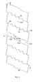
- FIG. 3 is a plan view of the tread pattern 10 of the tire 1 of the present invention spread flat for ease of illustration.
- the tire 1 having the tread pattern 10 may be suitably used as a tire for a passenger vehicle.
- the dimensions of the various elements of the tire in the following description are examples of values used in tires for passenger vehicles.
- the tire 1 of the present invention has a predetermined tire mounting orientation when mounted to the outside of a vehicle.
- the label CL in FIG. 3 indicates the centerline of the tire.
- the tire 1 is mounted on a vehicle with the region of the tread pattern 10 to the left of the centerline of the tire CL as seen in FIG. 3 facing inward and the region of the tread pattern 10 to the right of the tire centerline CL as seen in FIG. 3 facing outward; the tire may also be mounted on a vehicle with the reverse orientation.
- Information regarding mounting orientation is displayed, for example, on a surface of the tire, such as a side wall surface, in the form of letters, symbols, or the like.
- standard rim refers to an "application rim” as defined by the Japan Automobile Tyre Manufacturers Association Inc. (JATMA), a "design rim” as defined by the Tire and Rim Association, Inc.
- TRA a "measuring rim” as defined by the European Tyre and Rim Technical Organisation
- ETRTO European Tyre and Rim Technical Organisation
- Standard inner pressure refers to "maximum air pressure” as defined by JATMA, the maximum value in “tire load limits at various cold inflation pressures” as defined by TRA, or “inflation pressure” defined by ETRTO.
- the standard inner pressure is, for example, 180 kPa if the tire is for a passenger vehicle.
- Standard load refers to "maximum load resistance” defined by JATMA, the maximum value in “tire load limits at various cold inflation pressures” defined by TRA, or “load capacity” defined by ETRTO.
- the tire width direction in the present invention refers to the direction of the central axis of rotation of the tire 1
- the tire circumferential direction refers to a direction in which the rotating surface of the tread surface rotates, the rotating surface being formed when the tire 1 rotates around the central axis of rotation of the tire.
- the above directions are expressed in FIG. 3 .
- the tire rotation direction of the tread pattern 10 of the present invention is not particularly limited.
- the tire 1 of the present invention may have a pitch with the same dimensions as the tread pattern 10, illustrated in FIG. 3 , arranged in the tire circumferential direction, or the tire 1 may have a plurality of types of pitches with different dimensions from the tread pattern 10 arranged in the tire circumferential direction to allow for a pitch variation.
- the tread pattern 10 comprises two outer circumferential main grooves 11, 13 (first circumferential main grooves) that are parallel to the tire circumferential direction and are disposed outside of the tire centerline CL interposed therebetween in the tire width direction, shoulder land portions 51, 53 formed in the regions outside the outer circumferential main grooves 11, 13 in the tire width direction, shoulder lug grooves 61, 63, shoulder sipes 62, 64, and narrow circumferential grooves 71, 73.
- the tread pattern 10 preferably further comprises two inner circumferential main grooves 15, 17 (second circumferential main grooves) disposed between the two outer circumferential main grooves 11, 13, the inner circumferential main grooves 15, 17 defining a center land portion 21 through which the tire centerline CL passes.
- the circumferential main grooves 11, 13, 15, and 17 preferably includes a pair of main groove walls 12 and 12, 14 and 14, 16 and 16, and 18 and 18 that extend in the tire circumferential direction in a zig-zagging pattern, respectively. This increases the edge component of the tread surface, improving wet steering stability and steering stability on snow. Either or both of the circumferential main grooves 11, 13 and the circumferential main grooves 15, 17, may include zigzagging main groove walls.
- Each of the main groove walls 12, 14, 16, 18 has a shape comprising an alternating series of wall surfaces that are prominently inclined with respect to the tire circumferential direction and wall surfaces having an angle that is less inclined with respect to the tire circumferential direction than that of the first wall surfaces.
- the two main groove walls 16, 18 defining the center land portion 21, to be described hereafter, comprise bend points 16a, 18a that bend inward toward the center land portion 21 (i.e., the centerline of the tire), respectively, as illustrated in FIG. 7.
- FIG. 7 is a magnified view of the tread pattern 10 focusing on land portion blocks 22 in a center land portion 21.
- the two main groove walls 16, 18 are preferably formed so that one land portion block 22 is provided with two bend points 16a, 18a each. This allows both of two sipes 32, 30, to be described hereafter, to be provided so as to connect a bend point 16a and a bend point 18a.
- the groove depths and groove widths of the circumferential main grooves 11, 13, 15, 17 are equal, but may be different in a different embodiment. If the groove widths of the circumferential main grooves 11, 13, 15, 17 vary along the tire circumferential direction, the term "groove width" refers to the average groove width along the entire circumference of the tire circumferential direction, or, for example, the average groove width for ten different locations along the tire circumferential direction.
- the total value of the groove widths of the circumferential main grooves 11, 13, 15, 17 is preferably from 15 to 25% of the ground contact width 11w for the sake of striking a balance between wet steering stability, steering stability on snow, and wear resistance.
- shoulder lug grooves 61, 63 that extend from the outside in the tire width direction toward the adjacent outer circumferential main grooves 11, 13 are provided in the regions of the shoulder land portions 51, 53.
- the shoulder lug grooves 61, 63 are closed off midway without connecting with the outer circumferential main grooves 11, 13, so that the shoulder land portions 51, 53 form continuous land portions 52, 54 that continuously extend in the tire circumferential direction.
- continuous land portion refers to a plurality of land portions that are divided in the tire circumferential direction only by sipes in the tread surface, and are not divided in the tire circumferential direction by the shoulder lug grooves 61, 63.
- the shoulder lug grooves 61, 63 include outer regions 61A, 63A (first regions), and inner regions 61B, 63B (second regions) that are disposed in the regions closer to the outer circumferential main grooves 11, 13 than the outer regions 61A, 63A and have a shallower groove depth than the outer regions 61A, 63A.
- FIG. 4 is a cross-sectional view of the tread surface of the tire along line VIII-VIII (or line XI-XI) in FIG. 3 .
- FIG. 5 is a magnified view of region A (or region B) illustrated in FIG. 3 .
- FIG. 6 is an external view of the tire 1 from the outside with respect to the tire width direction, focusing on a region of a shoulder land portions 51, 53.
- the reference numbers in parentheses in FIGS. 4 to 6 are for elements related to the region of the shoulder land portion 53.
- the orientation of the two sides of the tire circumferential direction is the reverse of that for the numbers outside the parentheses. This also applies to FIG. 9 , which will be referred to hereafter.
- the groove depths 61Bd, 63Bd of the inner regions 61B, 63B are less than the groove depths 61Ad, 63Ad of the outer regions 61A, 63A, allowing the difference in rigidity between the continuous land portions 52, 54 and the outer regions 61A, 63A to be mitigated, improving steering performance when turning, and allowing uneven wearing to be suppressed.
- the lengths of the inner regions 61B, 63B in the tire width direction are preferably from 30 to 70% of the lengths of the shoulder lug grooves 61, 63 in the tire width direction for the sake of striking a balance between wet steering stability, steering stability on snow, and wear resistance, respectively.
- the groove depths 61Ad, 63Ad of the outer regions 61A, 63A are preferably from 50 to 80% of the groove depths of the outer circumferential main grooves 11, 13 for the sake of striking a balance between wet steering stability and steering stability on snow, and wear resistance, respectively.
- the groove depths 61Bd, 63Bd of the inner regions 61B, 63B are preferably less than the groove depths of the outer circumferential main grooves 11, 13, preferably from 20 to 60% of the groove depths of the outer circumferential main grooves 11, 13, for the sake of striking a balance between wet steering stability, steering stability on snow, and wear resistance, respectively.
- the lengths L52a, L54a in the tire width direction of the continuous land portions 52, 54 between closed ends 61e, 63e of the shoulder lug grooves 61, 63 and edges 12, 14 of the outer circumferential main grooves 11, 13 are preferably from 10 to 25%
- the lengths L61B, L63B in the tire width direction of the inner regions 61B, 63B are preferably from 35 to 65%
- the lengths L61A, L63A in the tire width direction of the outer regions 61A, 63A are preferably from 20 to 45%.
- the lengths L52a, L54a in the tire width direction of the continuous land portions 52, 54 are 18% of the ground contact width of the regions of the shoulder land portions 51, 53, the lengths L61B, L63B in the tire width direction of the inner regions 61B, 63B are 48%, and the lengths L61A, L63A in the tire width direction of the outer regions 61A, 63A is 34%.
- the shoulder lug grooves 61, 63 preferably include closed wall portions 61e, 63e that extend so as to connect groove floors 61Bb, 63Bb of the inner regions 61B, 63B and the tread surface, and stepped portions 61c, 63c that connect groove floors 61Ab, 63Ab of the outer regions 61A, 63A and the groove floors 61Bb, 63Bb of the inner regions 61B, 63B, the closed wall portions 61e, 63e and the stepped portions 61c, 63c each being inclined from 10 to 60° outward in the tire width direction with respect to a direction opposite the direction of the normal line of the tread surface.
- the closed wall portions 61e, 63e comprise inclined wall surfaces that are inclined outward in the tire width direction (or outward in the direction in which the shoulder lug grooves 61, 63 extend on the tread surface) at an angle ⁇ with respect to the direction opposite the direction of the normal line.
- the stepped portions 61c, 63c comprise inclined wall surfaces that are inclined outward in the tire width direction (or outward in the direction in which the shoulder lug grooves 61, 63 extend on the tread surface) at an angle of inclination ⁇ with respect to the direction opposite the direction of the normal line.
- the angle of inclination ⁇ of the closed wall portions 61e, 63e is the angle of inclination of with respect to an imaginary line extending in a direction opposite the direction of the normal line of the tread surface at the intersections between the tread surface and imaginary wall surfaces yielded by extending the inclined wall surfaces of the closed wall portions 61e, 63e.
- the angle of inclination ⁇ of the stepped portions 61c, 63c is the angle of inclination with respect to an imaginary line extending in the direction opposite the direction of the normal line of the tread surface that passes through the intersections of the inclined wall surfaces of the stepped portions 61c, 63c and imaginary lines (lines indicating the maximum depths of the groove floors) extending the groove floors 61Bd, 63Bd in the direction of extension (in FIG. 4 , the direction indicated by the double-headed arrow indicating the lengths L61B, L63B).
- the shape of the groove floors of the inner regions 61B, 63B may be parallel with the tread surface or extend in a straight line; in either case, the angle of inclination ⁇ is determined using imaginary lines extending from the groove floors.
- the closed wall portions 61e, 63e do not encompass aspects in which the groove floors of the inner regions 61B, 63B grow progressively shallower toward the outer circumferential main grooves 11, 13 until reaching the continuous land portions 52, 54. In other words, the closed wall portions 61e, 63e are positioned in a different region of the tire width direction from the groove floors of the inner regions 61B, 63B.
- the stepped portions 61c, 63c do not encompass aspects in which the groove floors of the outer regions 61A, 63A grow progressively shallower toward the outer circumferential main grooves 11, 13 until reaching the inner regions 61B, 63B, or in which the groove floors of the inner regions 61B, 63B grow progressively deeper toward the tire width direction until reaching the outer regions 61A, 63A.
- the stepped portions 61c, 63c are positioned in a different region of the tire width direction from the groove floors of the inner regions 61B, 63B.
- Both the angle of inclination ⁇ and the angle of inclination ⁇ being equal to or more than 10° allows differences in block rigidity between the continuous land portions 52, 54, the inner regions 61B, 63B, and the outer regions 61A, 63A to be mitigated, improving wear resistance, and wet steering stability and steering stability on snow. Because a great load is placed upon the tire 1 in the vicinity of the ground-contacting ends, it is desirable to ensure the groove volume of the shoulder lug grooves 61, 63 for the sake of improving steering stability on snow; having both the angle of inclination ⁇ and the angle of inclination ⁇ be no more than 60° ensures sufficient groove volume for the shoulder lug grooves 61, 63.
- the groove widths 61w, 63w of the shoulder lug grooves 61, 63 are preferably greater than the widest groove widths 31w of outer regions 31B of lug grooves 31, to be described hereafter, and the widest groove widths 33w, 35w of outer regions 33B, 35B of lug grooves 33, 35, also to be described hereafter.
- These shoulder lug grooves 61, 63 ensure groove volume while ensuring the block rigidity of the shoulder land portions 51, 53, thereby allowing for a balance between wear resistance, and wet steering stability and steering stability on snow.
- the shoulder lug grooves 61, 63 preferably extend from the outer end in the tire width direction to a length of equal to or more than 60%, more preferably from 70 to 80%, of the length of the ground-contacting regions of the shoulder land portions 51, 53. This ensures the block rigidity of the shoulder land portions 51, 53.
- the shoulder lug grooves 61, 63 preferably extend in an inclined manner with respect to the tire circumferential direction.
- the grooves have angles of from 75 to 90° with respect to the tire circumferential direction. Imparting the lug grooves 31, 33, 35 and shoulder lug grooves 61, 63 with different respective inclined angles yields a variety of inclined angles on the tread surface, thereby yielding superior wet steering stability and steering stability on snow when steering at small and medium steering angles while the vehicle is traveling.
- the groove widths 61w, 63w of the shoulder lug grooves 61, 63 is preferably greater than the lengths of the openings of arc-shaped grooves 81, 83 in the tire circumferential direction.
- the lengths of the continuous land portions 52, 54 in the tire width direction is preferably from 5 to 35% of the length of the ground-contacting regions of the shoulder land portions 51, 53 in the tire width direction.
- the ground-contacting regions of the shoulder land portions 51, 53 is the length of the ground contact width 11w of the tire in the tire width direction between the outer end in the tire width direction and the adjacent outer circumferential main groove 11, 13.
- the positions of the outer circumferential main grooves 11, 13 in the tire width direction is the center point of the lengths of the main groove walls 12, 14 in the tire width direction.
- shoulder sipes 62, 64 that connect with the inner regions 61B, 63B and extend toward the outer circumferential main grooves 11, 13 and narrow circumferential grooves 71, 73 that extend in the tire circumferential direction and have groove widths that are less than the groove widths 61w, 63w of the shoulder lug grooves 61, 63 are further formed in the regions of the shoulder land portions 51, 53.
- Providing shoulder sipes 62, 64 allows for the mitigation of block rigidity in the tire width direction, while ensuring block rigidity under force acting in the tire circumferential direction, unlike the lug grooves.
- the shoulder sipes 62, 64 are capable of taking snow into the grooves to improve snow shear force, thereby allowing for increased steering stability on snow.
- the ends of the shoulder sipes 62, 64 toward the outer circumferential main grooves 11, 13 may connected with the outer circumferential main grooves 11, 13, respectively, as illustrated in FIGS. 3 and 4 to 10 , or may be closed off within the continuous land portions 52, 54 without connecting with the outer circumferential main grooves 11, 13.
- the outer ends of the shoulder sipes 62, 64 with respect to the tire width direction are preferably provided within the inner regions 61B, 63B along lengths equivalent to from 20 to 100% of the groove lengths L61B, L63B of the inner regions 61B, 63B, respectively.
- the "outer ends of the shoulder sipes 62, 64 with respect to the tire width direction" are those parts thereof formed within the inner regions 61B, 63B.
- the shoulder sipes 62, 64 each may have a wavy shape on the tread surface extending with shifts in directions orthogonal to the direction of extension, as illustrated in FIGS. 3 and 5 , or may be straight lines.
- the shape of the shoulder sipes 62, 64 on the tread surface may be a wavy pattern extending with shifts in directions intersecting the direction in which the shoulder sipes 62, 64 extend on the tread surface, or may be a straight line.
- the "direction of extension" refers to the direction in which the grooves or the like extend along the tread surface unless noted otherwise.
- the shoulder sipes 62, 64 each may be formed in a wavy pattern by extending with shifts along the groove depth direction, or in straight lines with respect to the groove depth direction; a wavy pattern extending with shifts along the groove depth direction is preferable in order to ensure block rigidity during braking and driving.
- Groove depths 62d, 64d of the shoulder sipes 62, 64 are preferably less than the groove depths 61Ad, 63Ad of the outer regions 61A, 63A of the shoulder lug grooves 61, 63 and greater than the groove depths 61Bd, 63Bd of the inner regions 61B, 63B, as illustrated in FIG. 4 .
- Making the shoulder sipes more shallow than the outer regions 61A, 63A ensures block rigidity, and making the sipes deeper than the inner regions 61B, 63B sufficiently mitigates the block rigidity of the continuous land portions 52, 54 in the tire width direction and allows for ensured wet steering stability and steering stability on snow.
- the groove depths 62d, 64d of the shoulder sipes 62, 64 may be constant along the direction of extension, as illustrated in FIG. 4 , or may grow progressively shallower or deeper from the region closer to the outer circumferential main grooves 11, 13 toward the shoulder lug grooves 61, 63. If the groove depths 62d, 64d grow progressively shallower or deeper toward the shoulder lug grooves 61, 63, the groove floors of the shoulder sipes 62, 64 are preferably formed so as to extend in straight lines in the direction of extension.
- the outer ends of the shoulder sipes 62, 64 in the tire width direction are preferably formed so as to penetrate into the inner regions 61B, 63B of the shoulder lug grooves, as illustrated in FIGS. 4 to 6 .
- the outer ends of the shoulder sipes 62, 64 in the tire width direction are formed by extending into at least a part of the regions of the inner regions 61B, 63B of the shoulder lug grooves 61, 63.
- This sufficiently mitigates the block rigidity of the continuous land portions 52, 54 in the tire width direction and allows for ensured wet steering stability and steering stability on snow.
- the sipe depths of the shoulder sipes 62, 64 are greater than the groove depths of the inner regions 61B, 63B.
- the ends of the shoulder sipes 62, 64 may extend into at least a part of the regions of the inner regions 61B, 63B, or may extend into the entirety thereof.
- the narrow circumferential grooves 71, 73 are formed in the regions of the shoulder land portions 51, 53, as discussed above. Providing the narrow circumferential grooves 71, 73 improves wet steering stability and steering stability on snow, and sufficiently ensures the block rigidity of the shoulder land portions 51, 53 due to the groove widths 71w, 73w of the narrow circumferential grooves 71, 73 being less than the groove widths 61w, 63w of the shoulder lug grooves 61, 63.
- the narrow circumferential grooves 71, 73 intersect with the inner regions 61B, 63B of the shoulder lug grooves 61, 63.
- the groove widths 71w, 73w of the narrow circumferential grooves 71, 73 are preferably from 3 to 15% of the ground contact width of the shoulder land portions 51, 53 in order to minimize reductions in block rigidity.
- the groove depths 71d, 73d of the narrow circumferential grooves 71, 73 are preferably equal to or less than the groove depths 61Ad, 63Ad of the outer regions 61A, 63A, and equal to or less than the groove depths 61Bd, 63Bd of the inner regions 61B, 63B.
- the groove depths 71d, 73d of the narrow circumferential grooves 71, 73 are more preferably equal to or more than 2 mm.
- the groove depths 71d, 73d of the narrow circumferential grooves 71, 73 may be less than, greater than, or equal to the groove depths 61Ad, 63Ad of the inner regions 61A, 63A, and are, for example, equal to the groove depths 61Ad, 63Ad.
- the groove depths 71d, 73d of the narrow circumferential grooves 71, 73 may be less than, greater than, or equal to the groove depths of the shoulder sipes 62, 64, and are, for example, less than the groove depths of the shoulder sipes 62, 64.
- the groove depths 71d, 73d of the narrow circumferential grooves 71, 73 are less than the groove depths 61Ad, 63Ad of the outer regions 61A, 63A of the shoulder lug grooves 61, 63. This allow reductions in the block rigidity of the shoulder land portions 51, 53 to be minimized.
- the tread pattern 10 preferably further comprises a plurality of lug grooves 31 that traverse the region of the center land portion 21 and form a plurality of the region of land portion blocks 22 in the region of the center land portion 21.
- each of the lug grooves 31 includes a central region 31A (first lug groove region) being a central region of the direction of extension of the lug groove 31 along the tire width direction, and two outer regions 31B (second lug groove regions) that are regions on both sides of the central region 31A in the tire width direction and connected with the central region 31A.
- the central region 31A is formed by extending a predetermined distance in the direction of extension of the lug groove 31.
- the central region 31A has a groove width 31Aw that is less than those of the outer regions 31B, as illustrated in FIG. 7 , and a groove depth 31Ad that is less than those of the outer regions 31B, as illustrated in FIG. 8.
- FIG. 8 is a cross-sectional view of the tread surface of the tire 1 along line V-V in FIG. 3 .
- the provision of a region 31A configured in this way along part of the region in the direction of extension of the lug grooves 31 ensures the rigidity of the center land portion 21, minimizing reductions in wear resistance on dry road surfaces, and ensures groove volume in the lug grooves 31 necessary to improve water discharge ability and snow shear force, allowing for improved wet steering stability and steering stability on snow. In other words, it is possible to achieve a balance between wear resistance, and wet steering stability and steering stability on snow.
- the central region 31A is formed along a predetermined length of the region in the direction of extension of the lug grooves 31, block rigidity can be considerably improved over that of a conventional tire in which protrusions whose grooves are shallower (raised) than elsewhere in the region in the direction of extension are locally formed along the length of the lug groove. Because the central regions 31A are formed in those regions in the regions in the direction of extension of the lug grooves 31 that traverse the tire centerline CL, and the outer regions 31B are formed in the regions on both side of the central region 31A interposed therebetween, a high balance is achieved between wear resistance, and wet steering stability and steering stability on snow.
- the groove length L31A of the central regions 31A of the lug grooves 31 is preferably from 30 to 80% of the groove length L31 of the lug grooves 31, more preferably from 40 to 70%. Imparting the lug grooves 31A with a length L31A that is equal to or less than the maximum value of the range described above ensures sufficient groove volume in the lug grooves 31, and imparting the grooves with a length that is equal to or greater than the minimum value of the range described above ensures sufficient block rigidity in the center land portion 21.
- the groove length L31A of the central regions 31A of the lug grooves 31 is, for example, 55% of the groove length L31 of the lug grooves 31.
- the lug grooves 31 are preferably inclined with respect to the tire circumferential direction and extend in a direction connecting the upper left side and lower right side of FIG. 3 .
- the angle thereof with respect to the tire circumferential direction is, for example from 60 to 85° in the counterclockwise direction. Having the lug grooves 31 be highly inclined with respect to the tire circumferential direction ensures the block rigidity of the center land portion 21, and improves wet steering stability and steering stability on snow at low steering angles during driving.
- the lug grooves 31 may each extend in straight lines or in gentle curves.
- the tread pattern 10 preferably further comprises a plurality of lug grooves 33 that traverse the intermediate the region of land portion 23 and form a plurality of land portion blocks 24 in the region of the intermediate land portion 23, and a plurality of lug grooves 35 that traverse the region of the intermediate land portion 25 and form a plurality of land portion blocks 26 in the region of the intermediate land portion 25.
- the intermediate land portion 23 is defined by the outer circumferential main groove 11 and the inner circumferential main groove 15.
- the intermediate land portion 25 is defined by the outer circumferential main groove 13 and the inner circumferential main groove 17.
- the lug grooves 33, 35 include inner regions 33A, 35A (first lug groove regions) being regions in the direction of extension in the regions closer to the inner circumferential main grooves 15, 17, and outer regions 33B, 35B (second lug groove regions) being other regions in the direction of extension in the regions closer to the outer circumferential main grooves 11, 13 that connect with the inner regions 33A, 35A, respectively.
- FIG. 9 is a magnified view of the tread pattern 10 focusing on land portion blocks 24, 26 of the intermediate land portions 23, 25.
- the reference numbers in parentheses in FIG. 9 are for elements related to the region of the intermediate land portion 25.
- the inner regions 33A, 35A are formed by extending by a predetermined distance in the direction of extension of the lug grooves 33, 35. As illustrated in FIG. 9 , the inner regions 33A, 35A have groove widths 33Aw, 35Aw that are narrower than those of the outer regions 33B, 35B, and, as illustrated in FIG. 10 , have groove depths 33Ad, 35Ad that are shallower than those of the outer regions 33B, 35B.
- FIG. 10 is a cross-sectional view of the tread surface of the tire 1 along line VII-VII (or VI-VI) in FIG. 3 .
- the reference numbers in parentheses in FIG. 10 are for elements related to the region of the intermediate land portion 25.
- the provision of the inner regions 33A, 35A to the inside of the lug grooves 33, 35 in this way ensures the rigidity of the intermediate land portions 23, 25, minimizing reductions in wear resistance on dry road surfaces, and ensures groove volume within the lug grooves 33, 35 necessary to improve water discharge ability and snow shear force, allowing for improved wet steering stability and steering stability on snow.
- block rigidity can be considerably improved over cases in which projections formed by locally raising the floors of the lug grooves over other regions in the direction of extension are formed in the inner regions 33A, 35A.
- the inner regions 33A, 35A are formed in regions along the direction of extension of the lug grooves 33, 35 in the regions closer to the inner circumferential main grooves 15, 17, and the outer regions 33B, 35B are formed in other regions in the direction of extension in the regions closer to the outer circumferential main grooves 11, 13, thereby allowing for a high balance between wear resistance and wet steering stability and steering stability on snow.
- the inner regions 33A, 35A are formed so as to connect with the inner circumferential main grooves 15, 17, and the outer regions 33B, 35B are connected with the inner regions 33A, 35A and the outer circumferential main grooves 11, 13, respectively. This allows the rigidity of the region of the tread portion 2 near the centerline CL to be increased and wear resistance to be improved while ensuring wet steering stability and steering stability on snow.
- the lengths L33A, L35A of the inner regions 33A, 35A of the lug grooves 33, 35 is preferably from 30 to 80%, more preferably from 40 to 70%, of the groove lengths L33, L35 of the lug grooves 33, 35. Setting the lengths L33A, L33A of the lug grooves 33, 35 at or below the maximum value of the range described above ensures sufficient groove volume in the lug grooves 33, 35, and setting the lengths at or above the minimum value of the range described above ensures sufficient block rigidity in the intermediate land portions 23, 25.
- the groove lengths L31A, L33A of the inner regions 33A, 35A are, for example, 55% of the groove lengths L33, L33 of the lug grooves 33, 35.
- the proportion of the groove lengths L33A, L35A of the inner regions 33A, 35A to the groove lengths L33, L35 of the lug grooves 33, 35 may be equal to or different from the proportion of the groove length L31A of the central region 31A to the groove length L31 of the lug grooves 31. Both of the groove lengths L33A, L35A of the lug grooves 33, 35 may occupy equal or different proportions to the groove lengths L33, L35 of the lug grooves 33, 35.
- Arc-shaped Grooves 81, 83 are preferably formed in the land portion blocks 24, 26 of the intermediate land portions 23, 25.
- the arc-shaped grooves 81, 83 extend in arc-shaped curves from the outer circumferential main grooves 11, 13 defining ends of the land portion blocks 24, 26 in the tire width direction to the lug grooves 33, 35 defining ends of the land portion blocks 24, 26 in the tire circumferential direction, and are further formed so as to traverse the lug grooves 33, 35 and be closed off within other land portion blocks 24, 26 that are adjacent in the tire circumferential direction.
- the arc-shaped grooves 81, 83 comprise openings that connect with the outer circumferential main grooves 11, 13, and closed ends that are closed off within other land portion blocks 24, 26 that are adjacent in the tire circumferential direction.
- Suitably disposing arc-shaped grooves 81, 83 as described above along with the lug grooves 33, 35 adjacent to the arc-shaped grooves 81, 83, the outer circumferential main grooves 11, 13, and the inner circumferential main grooves 15, 17 better ensures wet steering stability and steering stability on snow.
- the groove depths of the arc-shaped grooves 81, 83 there is no particular limitation upon the groove depths of the arc-shaped grooves 81, 83; for example, the depths may be identical to the groove depths of the lug grooves 33, 35 at positions intersecting the lug grooves 33, 35.
- the lug grooves 33, 35 preferably extend in an inclined manner with respect to the tire circumferential direction in a direction connecting the lower left side and the upper right side of FIG. 3 .
- the angle thereof with respect to the tire circumferential direction is, for example from 60 to 85° in the clockwise direction.
- Having the lug grooves 31 be highly inclined with respect to the tire circumferential direction ensures the block rigidity of the intermediate land portions 23, 25, and improves wet steering stability and steering stability on snow at low steering angles during driving.
- having the lug grooves 33, 35 be tilted in the oppose direction with respect to the tire circumferential direction as the lug grooves 31 ensures steering performance when turning left or right.
- the elements in the region of the intermediate land portion 23 and the elements in the region of the intermediate land portion 25 are formed so as to be symmetrical with respect to a point on the tire centerline CL; however, they need not be symmetrically formed in other embodiments.
- the lug grooves 33, 35 may each extend in straight lines or in gentle curves.
- the tread pattern 10 preferably further comprises sipes 30, 32, 34, 36 in the land portion blocks 22, 24, 26 that extend in parallel with the lug grooves 31, 33, 35, respectively.
- the term "sipe” refers to a groove having widths of less than 1.5 mm and groove depths of less than 7 mm.
- the lug grooves have a groove width of 1.5 mm or more and have a groove depth of 7 mm or more.
- Sipes 30, 32, 34, 36 configured in this way are useful in ensuring, in conjunction with the outer circumferential main grooves 11, 13, inner circumferential main grooves 15, 17, lug grooves 31, 33, 35, and shoulder lug grooves 61, 63 (to be described hereafter), the basic wet steering stability and steering stability on snow required of an all-season tire.
- the sipes 32, 30 in the region of the center land portion 22 preferably extend across the tire centerline CL so as to connect both of the bend points 16a, 18a. This allows stress concentrated near the bend points 16a, 18a to escape through the deformation of the sipes 32, 30, improving wear resistance. It is preferable that two sipes 32 and 20 be formed in a single land portion block, the two sipes 32, 30 being formed so as to face each other with respect to a center 22a of the land portion block 22 on the tread surface and extend in a wavy pattern formed with shifts in directions orthogonal to the direction of extension of each sipe extend.
- the shapes of the sipes 32, 30 on the tread surface exhibit point symmetry with respect to the center 22a; however, the shapes of the two sipes 32, 30 on the tread surface may also exhibit, for example, linear symmetry with respect to a line extending through the center 22a in a direction parallel to the direction of extension of the lug groove 31.
- Providing the sipes 32, 30 in this way causes the land portion block 22 to have uniform block rigidity along the tire circumferential direction, and improves uneven wear resistance when braking and driving.
- the wavy shapes of the sipes 32, 30 suppresses the formation of non-uniform ground contact pressure distributions when force is applied from a direction other than the direction in which the sipes 32, 30 extend and the land portion blocks 22 tend to collapse and deform, thereby minimizing reductions in ground contact area.
- the sipes 32, 30 may be formed so as to extend in a wavy pattern formed with shifts in the groove depth direction, or so as to extend in a straight line in the groove depth direction.
- One sipe 34, 36 is formed in the land portions 23, 25 for each land portion block 24, 26.
- One end of the sipes 34, 36 is connected to the inner circumferential main grooves 15, 17, and the other end is closed off within the land portion blocks 24, 25 without being connected to the arc-shaped grooves 81, 83.
- the groove depth of the outer regions 61A, 63A of the shoulder lug grooves 61, 63 is from 8 to 12 mm.
- the groove depth of the inner regions 61B, 63B is from 2 to 8 mm.
- the groove depth of the shoulder lug grooves 61, 63 is from 8 to 12 mm.
- the groove width of the narrow circumferential grooves 71, 73 is from 1.5 to 5 mm.
- the ground contact width of the tire is from 130 to 230 mm, and the ground contact width of the ground contact width of the regions of the shoulder land portions 51, 53 in the ground contact width is from 25 to 45 mm.
- the lengths L52a, L54a of the continuous land portions 52, 54 in the tire width direction is from 3 to 10 mm.
- the length of the inner regions 61B, 63B in the tire width direction is from 5 to 25 mm.
- the angle of inclination ⁇ of the closed wall portions 61e, 63e and the angle of inclination ⁇ of the stepped portions 61c, 63c are from 10 to 60° each.
- the groove depth of the shoulder sipes 62, 64 is from 2 to 12 mm.
- inner regions 61B, 63B having a shallower groove depth than the outer regions 61A, 63A are formed in the shoulder lug grooves 61, 63, shoulder sipes 62, 64 and narrow circumferential grooves 71, 73 are formed in the shoulder land portions 51, 53, and the narrow circumferential grooves 71, 73 intersect with the inner regions 61B, 63B.
- Narrow circumferential grooves 71, 73 are disposed in the regions of the inner regions 61B, 63B, the block rigidity of which has been ensured as described above, thereby minimizing reductions in block rigidity and allowing for a balance between wear resistant, and wet steering stability and steering stability on snow.
- the lengths L52a, L54a of the continuous land portions 52, 54 in the tire width direction is from 10 to 25%
- the lengths of the inner regions 61B, 63B of the shoulder lug grooves 61, 63 in the tire width direction is from 35 to 65%
- the length of the outer regions 61A, 63A in the tire width direction is from 20 to 45%, thereby improving the balance between wear resistance, and wet steering stability and steering stability on snow.
- the angle of inclination ⁇ of the closed wall portions 61e, 63 of the shoulder lug grooves 61, 63 and the angle of inclination ⁇ of the stepped portions 61c, 63c are each inclined from 10 to 60° outward in the tire width direction with respect to the direction opposite the direction of the normal line of the tread surface. Both the angle of inclination ⁇ and the angle of inclination ⁇ being equal to or more than 10° allows differences in block rigidity between the continuous land portions 52, 54, the inner regions 61B, 63B, and the outer regions 61A, 63A to be mitigated, improving wear resistance, and wet steering stability and steering stability on snow.
- the groove depth of the shoulder sipes 62, 64 grows progressively shallower from the regions closer to outer circumferential main grooves 11, 13 toward the shoulder lug grooves 61, 63, thereby further mitigating the block rigidity of the continuous land portions 52, 54 in the tire width direction, and allowing wet steering stability and steering stability on snow to be ensured.
- the groove depth of the shoulder sipes 62, 64 is less than the groove depth of the outer regions of the shoulder lug grooves and greater than the groove depth of the inner region, thereby ensuring block rigidity in the shoulder land portions 51, 53, and sufficiently mitigating the block rigidity of the continuous land portions 52, 54 in the tire width direction, thereby allowing for ensured wet steering stability and steering stability on snow.
- the sipe depth of the shoulder sipes is greater than the groove depth of the inner regions 61B, 63B, and the outer ends of the shoulder sipes 62, 64 in the tire width direction are formed by extending into at least a part of the regions of the inner regions 61B, 63B of the shoulder lug grooves 61, 63, thereby ensuring sufficient block rigidity of the continuous land portions 52, 54 in the tire width direction, and allowing for ensured wet steering stability and steering stability on snow.
- the groove depth of the outer regions 61B, 63B of the shoulder lug grooves 61, 63 is less than the groove depth of the outer circumferential main grooves 11, 13, thereby allowing for a balance between wear resistance, and steering stability on snow and wet steering stability.
- the length of the inner regions 61B, 63B of the shoulder lug grooves 61, 63 in the tire width direction is from 30 to 70% of the length of the shoulder lug grooves 61, 63 in the tire width direction, thereby allowing for a balance between wear resistance, and steering stability on snow and wet steering stability.
- the groove depth of the narrow circumferential grooves 71, 73 is equal to or less than the groove depth of the inner regions 61A, 63A of the shoulder lug grooves 61, 63, thereby allowing for a balance between wear resistance, and steering stability on snow and wet steering stability.
- narrow first lug groove regions 31A, 33A, 35A having raised floors in either the lug grooves 31 in the region of the center land portion 21 or the lug grooves 33, 35 in the intermediate land portions 23, 25 of the tread pattern 10 minimizes reductions in the block rigidity of center land portions 21 and intermediate land portions 23, 25 that are adjacent in the tire circumferential direction, allowing for ensured wear resistance on dry road surfaces, and ensures the groove volume of the lug grooves 31, 33, 35, allowing for ensured wet steering stability and steering stability on snow. This allows for a balance between wear resistance, and wet steering stability and steering stability on snow.
- the groove length of the central regions 31A of the lug grooves 31 in the region of the center land portion 21 is from 30 to 80% of the groove length of the lug grooves 31, thereby ensuring sufficient groove volume in the lug grooves 31 and sufficient block rigidity in the center land portion 21, in turn allowing for a balance between wear resistance, and steering stability on snow and wet steering stability.
- the groove width of the shoulder lug grooves 61, 63 is greater than the widest groove width of the outer regions 31B of the lug grooves 31 in the region of the center land portion 21 and the widest groove width of the outer regions 33B, 35B of the lug grooves 33, 35 in the regions of the intermediate land portions 23, 25, allowing for ensured groove volume while ensuring the block rigidity of the shoulder land portions 51, 53, and allowing for a balance between wear resistance, and wet steering stability and steering stability.
- the lengths of the continuous land portions, the inner regions, and the outer regions in the tire width direction with respect to the ground contact width of the regions of the shoulder land portions need not fall within the ranges described above.
- the angles of inclination of the closed wall portions of the shoulder lug grooves and the stepped portions with respect to the direction opposite the direction of the normal line of the tread surface may be less than 10° or greater than 60° outward in the tire width direction.
- the sipe depth of the shoulder sipes need not be less than the groove depth of the outer regions of the shoulder lug grooves and greater than the groove depth of the inner regions.
- the groove floors of the inner regions of the shoulder lug grooves need not be raised to form a step difference with the groove floors of the outer regions.
- the outer ends of the shoulder sipes in the tire width direction need not be formed so as to penetrate into the inner regions of the shoulder lug grooves.
- the shoulder lug grooves may be connected to the outer circumferential main grooves, thereby forming a plurality of land portion blocks in the tire circumferential direction.
- the tread pattern may not have the shoulder land portions.
- the lug grooves including the first lug groove regions and the second lug groove regions may be in at least one of the center land portion 21 and the intermediate land portion 23 and intermediate land portion 25.
- the number of circumferential main grooves is not limited to four; there may be only three, or five or more.
- Test tires were manufactured to study the effects of the tread pattern 10 of the tire 1 of the present invention.
- the tire size was P265/70R17 113T.
- tires provided with tread patterns having the specifications shown in Tables 1 to 9 below were manufactured.
- the groove width of each of the circumferential main grooves was 10 mm.
- the groove depth of the inner regions of the shoulder lug grooves was 4 mm, and the groove depth of the outer regions was 8 mm.
- the tires shown in Tables 1 to 9 were similar to that of Working Example 1 apart from having the specifications shown in the tables, and were similar to the tread pattern illustrated in FIG. 3 in terms of other specifications.
- Average lateral acceleration was measured for 5 laps at a maximum speed on a 30 m-radius curved course of an outdoor tire testing facility having a wet road surface with a water depth of 1 mm.
- the evaluation was carried out by taking the inverse of the measurement values and expressing the inverse of the measurement values of the tire of the Conventional Example as 100. Larger index values indicate superior wet steering stability.
- Measurement was performed in a manner similar to the procedure used to measure wet steering stability as described above, except that a snow-covered road surface was driven on instead of a wet road surface having a water depth of 1 mm.
- the evaluation was carried out by taking the inverse of the measurement values and expressing the inverse of the measurement values of the tire of the Conventional Example as 100. A greater index value indicates superior steering stability on snow.
- “Widthwise length of inner region of shoulder lug groove/overall widthwise length” indicates the ratio of the length of the inner regions of the shoulder lug grooves in the tire width direction to the length of the shoulder lug grooves in the tire width direction. As shown in Table 7, there was a high balance between wear resistance, and steering stability on snow and wet steering stability when the length of the inner regions of the shoulder lug grooves in the tire width direction was from 30 to 70% of the length of the shoulder lug grooves in the tire width direction (Working Examples 26 to 28).
- “Groove length of central region of lug groove in center land portion/lug groove length” indicates the ratio of the groove length of the central regions of the region of the lug grooves in the region of the center land portion to the groove length of the lug grooves. As shown in Table 9, there was a high balance between wear resistance, and steering stability on snow and wet steering stability when the groove length of the central regions of the region of the lug grooves in the region of the center land portion was from 30 to 80% of the groove length of the lug grooves (Working Examples 36 to 38).
Landscapes
- Engineering & Computer Science (AREA)
- Mechanical Engineering (AREA)
- Tires In General (AREA)
Abstract
Description
- The present invention relates to a pneumatic tire provided with a tread pattern.
- All-season tires used year-round must be capable of handling various types of road surface conditions, such as dry, wet, and snowy. A tire comprising, for example, two outer circumferential main grooves disposed to the outside in a tire width direction and a shoulder land portion formed in regions to the outside of the outer circumferential main grooves in a tire circumferential direction is known in the art as a tire possessing the ability to handle various types of road surface conditions (see Patent Document 1). The tire of Patent Document 1 is provided with shoulder lug grooves in the regions of the shoulder land portions that extend from the outer side in the tire width direction to the outer circumferential main grooves and form a plurality of land portion blocks. Shallow-grooved regions in which the groove depth is shallow are formed in the shoulder lug grooves in the regions closer to the outer circumferential main grooves, and shoulder sipes that connect to the outer circumferential main grooves are formed in these shallow grooved regions.
In accordance with the tire of Patent Document 1, the shoulder sipes in the shallow grooved regions close in response to external forces acting in the tire circumferential direction, allowing block rigidity to be maintained, and external forces acting in the tire width direction mitigate block rigidity, allowing for increased ground contact and maintaining wet steering stability. - Patent Document 1: Japanese Patent No.
3482033B - An all-season tire preferably exhibits wear resistance on dry road surfaces, and steering stability on wet and snowy road surfaces. However, the tire disclosed in Patent Document 1 does not exhibit a sufficient balance between these various capabilities.
- The present invention provides a pneumatic tire that exhibits a superior balance between wear resistance on dry road surfaces and wet steering stability and steering stability on snow.
- An aspect of the present invention is a pneumatic tire provided with a tread pattern in a tread section, wherein
the tread pattern includes: - two first circumferential main grooves parallel to a tire circumferential direction, the two first circumferential main grooves being disposed on both sides of a centerline of the tire in a tire width direction;
- shoulder land portions formed in the regions outside the first circumferential main grooves in the tire width direction;
- shoulder lug grooves provided in the regions of the shoulder land portions, the shoulder lug grooves extending from outer sides in the tire width direction toward the first circumferential main grooves, the shoulder lug grooves being closed off midway without connecting with the first circumferential main grooves, and the shoulder lug grooves including first regions and second regions, the second regions disposed in the regions closer to the first circumferential main grooves than the first regions and having a shallower groove depth than the first regions;
- shoulder sipes formed in the regions of the shoulder land portions, the shoulder sipes being connected to the second regions of the shoulder lug grooves, and the shoulder sipes extending toward the first circumferential main grooves; and narrow circumferential grooves formed in the regions of the shoulder land portions, the narrow circumferential grooves extending in the tire circumferential direction, and the narrow circumferential grooves having a narrower groove width than the shoulder lug grooves;
- the narrow circumferential grooves intersecting with the second regions of the shoulder lug grooves.
- With respect to the ground contact width of the regions of the shoulder land portions in the ground contact width of the tire,
the length in the tire width direction of land portions between the closed ends of the shoulder lug grooves and the edges of the first circumferential main grooves is preferably from 10 to 25%,
the length in the tire width direction of the second regions in the shoulder lug grooves is preferably from 35 to 65%, and
the length in the tire width direction of the first regions of the shoulder lug grooves is preferably from 20 to 45%. - It is preferable that the shoulder lug grooves further include closed wall portions extending so as to connect the floors of the grooves in the second regions and the tread surface, and stepped portions connecting the floors of the grooves in the first regions and the floors of the grooves in the second regions, and
the closed wall portions and the stepped portions are each inclined from 10 to 60° outward in the tire width direction with respect to a direction opposite the direction of the normal line of the tread surface. - The shoulder sipes preferably have a sipe depth that is less than the groove depth of the first regions of the shoulder lug grooves and greater than the groove depth of the second regions.
- It is preferable that the shoulder sipes have a sipe depth greater than the groove depth of the second regions of the shoulder lug grooves, and outer ends of the shoulder sipes in the tire width direction are formed by extending into at least a part of the regions of the inner regions of the shoulder lug grooves.
- The sipe depth of the shoulder sipes may progressively decrease from the regions closer to the first circumferential main grooves toward the shoulder lug grooves.
- The groove depth of the second regions of the shoulder lug grooves is preferably less than the groove depth of the first circumferential main grooves.
- The length of the second regions of the shoulder lug grooves in the tire width direction is preferably from 30 to 70% of the length of the shoulder lug grooves in the tire width direction.
- The groove depth of the narrow circumferential grooves is preferably equal to or less than the groove depth of the first regions of the shoulder lug grooves.
- It is preferable that the tread pattern further comprise
second circumferential main grooves disposed between the two first circumferential main grooves and the second circumferential main grooves defining a center land portion, the centerline of the tire passing therethrough, and
a plurality of lug grooves traversing the region of the center land portion and the regions of two intermediate land portions defined by the first circumferential main grooves and the inner circumferential main grooves to form a plurality of land portion blocks in the region of the center land portion and the regions of the intermediate land portions;
at least one of the lug grooves provided in the region of the center land portion and the lug grooves provided in the regions of the intermediate land portions include first lug groove regions being a part of regions in the direction of extension and second lug groove regions connecting with the first lug groove regions and the second lug groove regions are the other regions in the direction of extension; and
the first lug groove regions have a narrower groove width than the second lug groove regions and a shallower groove depth than the second lug groove regions. - The first lug groove regions of the lug grooves in the region of the center land portion preferably have a groove length that is from 30 to 80% of the groove length of the lug grooves.
- The shoulder lug grooves preferably have a groove width that is greater than the widest groove width of the second lug groove region of the lug grooves in the region of the center land portion and the second lug groove regions of the lug grooves in the intermediate land portions.
- The tire according to the present invention exhibits a superior balance between wear resistance on dry road surfaces and wet steering stability and steering stability on snow.
-
- FIG. 1
- is a visual appearance view of an entire tire of an embodiment of the present invention.
- FIG. 2
- is a half cross-sectional view of a portion of the tire illustrated in
FIG. 1 . - FIG. 3
- is a view of the tread pattern of the tire illustrated in
FIG. 1 spread flat for ease of illustration. - FIG. 4
- is a cross-sectional view of the tread surface of the tire according to the present embodiment along line VIII-VIII (or IX-IX) in
FIG. 3 . - FIG. 5
- is a magnified view of region A (or region B) illustrated in
FIG. 3 . - FIG. 6
- is an external view of the tire illustrated in
FIG. 1 from the outside with respect to the tire width direction, focusing on a region of a shoulder land portion. - FIG. 7
- is a magnified view of the tread pattern illustrated in
FIG. 3 focusing on land portion blocks in a center land portion. - FIG. 8
- is a cross-sectional view of the tread surface of the tire illustrated in
FIG. 1 along line V-V inFIG. 3 . - FIG. 9
- is a magnified view of the tread pattern illustrated in
FIG. 3 focusing on land portion blocks in an intermediate land portion. - FIG. 10
- is a cross-sectional view of the tread surface of the tire illustrated in
FIG. 1 along line VII-VII (or VI-VI) inFIG. 3 . - The following is a detailed description of the pneumatic tire according to the present invention.
FIG. 1 illustrates the exterior of a pneumatic tire 1 of an embodiment of the present invention.
The pneumatic tire (hereafter referred to as a tire) 1 is a tire for a passenger vehicle.
The structure and rubber members of the tire 1 of the present invention may be either publicly known or novel, and are not particularly limited in the present invention. - As illustrated in
FIG. 2 , the tire 1 includes atread portion 2, aside wall 3, abead 4, acarcass layer 5, and abelt layer 6.FIG. 2 is a half cross-sectional view illustrating a portion of the tire 1. The tire 1 also includes an inner liner layer and the like that are not illustrated in the drawings. Theside wall 3 and thebead 4 are each formed as pairs that are arranged on both sides in the tire width direction so as to sandwich thetread portion 2.
Thetread portion 2, thebead 4, thebelt layer 6, the inner liner, and the like may be either publicly known or novel, and are not particularly limited in the present invention. - The
tread pattern 10 characterizing the present invention as illustrated inFIG. 3 is formed in thetread portion 2 of the tire 1 according to the present invention.FIG. 3 is a plan view of thetread pattern 10 of the tire 1 of the present invention spread flat for ease of illustration. The tire 1 having thetread pattern 10 may be suitably used as a tire for a passenger vehicle. The dimensions of the various elements of the tire in the following description are examples of values used in tires for passenger vehicles. - The tire 1 of the present invention has a predetermined tire mounting orientation when mounted to the outside of a vehicle. The label CL in
FIG. 3 indicates the centerline of the tire. The tire 1 is mounted on a vehicle with the region of thetread pattern 10 to the left of the centerline of the tire CL as seen inFIG. 3 facing inward and the region of thetread pattern 10 to the right of the tire centerline CL as seen inFIG. 3 facing outward; the tire may also be mounted on a vehicle with the reverse orientation. Information regarding mounting orientation is displayed, for example, on a surface of the tire, such as a side wall surface, in the form of letters, symbols, or the like. - While the tire 1 is mounted on a vehicle, the
tread pattern 10 comes into contact with the road surface in a region of the tire width direction indicated by aground contact width 11w. The ground-contacting ends are determined as described below. The ground-contacting ends are end portions in the tire width direction of a ground-contacting surface when thetire 10 is brought into contact with a horizontal surface under conditions in which thetire 10 is fitted to a standard rim and inflated to a standard inner pressure, and a load to be applied is set to 88% of a standard load. Herein, "standard rim" refers to an "application rim" as defined by the Japan Automobile Tyre Manufacturers Association Inc. (JATMA), a "design rim" as defined by the Tire and Rim Association, Inc. (TRA), or a "measuring rim" as defined by the European Tyre and Rim Technical Organisation (ETRTO). "Standard inner pressure" refers to "maximum air pressure" as defined by JATMA, the maximum value in "tire load limits at various cold inflation pressures" as defined by TRA, or "inflation pressure" defined by ETRTO. The standard inner pressure is, for example, 180 kPa if the tire is for a passenger vehicle. "Standard load" refers to "maximum load resistance" defined by JATMA, the maximum value in "tire load limits at various cold inflation pressures" defined by TRA, or "load capacity" defined by ETRTO. - The tire width direction in the present invention refers to the direction of the central axis of rotation of the tire 1, and the tire circumferential direction refers to a direction in which the rotating surface of the tread surface rotates, the rotating surface being formed when the tire 1 rotates around the central axis of rotation of the tire. The above directions are expressed in
FIG. 3 . The tire rotation direction of thetread pattern 10 of the present invention is not particularly limited.
The tire 1 of the present invention may have a pitch with the same dimensions as thetread pattern 10, illustrated inFIG. 3 , arranged in the tire circumferential direction, or the tire 1 may have a plurality of types of pitches with different dimensions from thetread pattern 10 arranged in the tire circumferential direction to allow for a pitch variation. - The
tread pattern 10 comprises two outer circumferentialmain grooves 11, 13 (first circumferential main grooves) that are parallel to the tire circumferential direction and are disposed outside of the tire centerline CL interposed therebetween in the tire width direction,shoulder land portions main grooves shoulder lug grooves shoulder sipes circumferential grooves - The
tread pattern 10 preferably further comprises two inner circumferentialmain grooves 15, 17 (second circumferential main grooves) disposed between the two outer circumferentialmain grooves main grooves 15, 17 defining acenter land portion 21 through which the tire centerline CL passes. - The circumferential
main grooves main groove walls main grooves main grooves 15, 17, may include zigzagging main groove walls. Each of themain groove walls main groove walls center land portion 21, to be described hereafter, comprisebend points FIG. 7. FIG. 7 is a magnified view of thetread pattern 10 focusing on land portion blocks 22 in acenter land portion 21. The twomain groove walls land portion block 22 is provided with twobend points sipes bend point 16a and abend point 18a. - The groove depths and groove widths of the circumferential
main grooves main grooves main grooves ground contact width 11w for the sake of striking a balance between wet steering stability, steering stability on snow, and wear resistance. - As illustrated in
FIG. 3 ,shoulder lug grooves main grooves shoulder land portions - The
shoulder lug grooves main grooves shoulder land portions continuous land portions shoulder lug grooves - As illustrated in
FIGS. 4 to 6 , theshoulder lug grooves outer regions inner regions main grooves outer regions outer regions FIG. 4 is a cross-sectional view of the tread surface of the tire along line VIII-VIII (or line XI-XI) inFIG. 3 .FIG. 5 is a magnified view of region A (or region B) illustrated inFIG. 3 .FIG. 6 is an external view of the tire 1 from the outside with respect to the tire width direction, focusing on a region of ashoulder land portions FIGS. 4 to 6 are for elements related to the region of theshoulder land portion 53. When referring to the numbers in parentheses inFIGS. 4 to 6 , the orientation of the two sides of the tire circumferential direction is the reverse of that for the numbers outside the parentheses. This also applies toFIG. 9 , which will be referred to hereafter. The groove depths 61Bd, 63Bd of theinner regions outer regions continuous land portions outer regions - The lengths of the
inner regions shoulder lug grooves outer regions main grooves inner regions main grooves main grooves - With respect to the ground contact width of the regions of the
shoulder land portions continuous land portions closed ends shoulder lug grooves edges main grooves inner regions outer regions continuous land portions shoulder land portions inner regions outer regions - The
shoulder lug grooves wall portions inner regions portions outer regions inner regions closed wall portions portions closed wall portions shoulder lug grooves portions shoulder lug grooves closed wall portions closed wall portions portions portions FIG. 4 , the direction indicated by the double-headed arrow indicating the lengths L61B, L63B). The shape of the groove floors of theinner regions closed wall portions inner regions main grooves continuous land portions closed wall portions inner regions portions outer regions main grooves inner regions inner regions outer regions portions inner regions - Both the angle of inclination θ and the angle of inclination δ being equal to or more than 10° allows differences in block rigidity between the
continuous land portions inner regions outer regions shoulder lug grooves shoulder lug grooves - The
groove widths 61w, 63w of theshoulder lug grooves outer regions 31B oflug grooves 31, to be described hereafter, and the widest groove widths 33w, 35w ofouter regions lug grooves shoulder lug grooves shoulder land portions - The
shoulder lug grooves shoulder land portions shoulder land portions - The
shoulder lug grooves lug grooves shoulder lug grooves
Thegroove widths 61w, 63w of theshoulder lug grooves grooves
The lengths of thecontinuous land portions circumferential grooves main grooves 11, 13) is preferably from 5 to 35% of the length of the ground-contacting regions of theshoulder land portions shoulder land portions ground contact width 11w of the tire in the tire width direction between the outer end in the tire width direction and the adjacent outer circumferentialmain groove main grooves main groove walls - As illustrated in
FIGS. 4 to 6 ,shoulder sipes inner regions main grooves circumferential grooves groove widths 61w, 63w of theshoulder lug grooves shoulder land portions shoulder sipes - The ends of the
shoulder sipes main grooves main grooves FIGS. 3 and4 to 10 , or may be closed off within thecontinuous land portions main grooves shoulder sipes inner regions inner regions shoulder sipes inner regions
The shoulder sipes 62, 64 each may have a wavy shape on the tread surface extending with shifts in directions orthogonal to the direction of extension, as illustrated inFIGS. 3 and5 , or may be straight lines. In other words, the shape of theshoulder sipes shoulder sipes -
Groove depths shoulder sipes outer regions shoulder lug grooves inner regions FIG. 4 . Making the shoulder sipes more shallow than theouter regions inner regions continuous land portions - The
groove depths shoulder sipes FIG. 4 , or may grow progressively shallower or deeper from the region closer to the outer circumferentialmain grooves shoulder lug grooves groove depths shoulder lug grooves shoulder sipes shoulder sipes inner regions FIGS. 4 to 6 . Specifically, the outer ends of theshoulder sipes inner regions shoulder lug grooves continuous land portions shoulder sipes inner regions shoulder sipes inner regions - The narrow
circumferential grooves shoulder land portions circumferential grooves shoulder land portions groove widths circumferential grooves groove widths 61w, 63w of theshoulder lug grooves
The narrowcircumferential grooves inner regions shoulder lug grooves circumferential grooves inner regions circumferential grooves continuous land portions main grooves outer regions - The
groove widths circumferential grooves shoulder land portions groove depths circumferential grooves outer regions inner regions groove depths circumferential grooves - The
groove depths circumferential grooves inner regions groove depths circumferential grooves shoulder sipes shoulder sipes - The
groove depths circumferential grooves outer regions shoulder lug grooves shoulder land portions - The
tread pattern 10 preferably further comprises a plurality oflug grooves 31 that traverse the region of thecenter land portion 21 and form a plurality of the region of land portion blocks 22 in the region of thecenter land portion 21. - As illustrated in
FIG. 7 , each of thelug grooves 31 includes acentral region 31A (first lug groove region) being a central region of the direction of extension of thelug groove 31 along the tire width direction, and twoouter regions 31B (second lug groove regions) that are regions on both sides of thecentral region 31A in the tire width direction and connected with thecentral region 31A. Thecentral region 31A is formed by extending a predetermined distance in the direction of extension of thelug groove 31. Thecentral region 31A has a groove width 31Aw that is less than those of theouter regions 31B, as illustrated inFIG. 7 , and a groove depth 31Ad that is less than those of theouter regions 31B, as illustrated inFIG. 8. FIG. 8 is a cross-sectional view of the tread surface of the tire 1 along line V-V inFIG. 3 .
The provision of aregion 31A configured in this way along part of the region in the direction of extension of thelug grooves 31 ensures the rigidity of thecenter land portion 21, minimizing reductions in wear resistance on dry road surfaces, and ensures groove volume in thelug grooves 31 necessary to improve water discharge ability and snow shear force, allowing for improved wet steering stability and steering stability on snow. In other words, it is possible to achieve a balance between wear resistance, and wet steering stability and steering stability on snow. In particular, because thecentral region 31A is formed along a predetermined length of the region in the direction of extension of thelug grooves 31, block rigidity can be considerably improved over that of a conventional tire in which protrusions whose grooves are shallower (raised) than elsewhere in the region in the direction of extension are locally formed along the length of the lug groove. Because thecentral regions 31A are formed in those regions in the regions in the direction of extension of thelug grooves 31 that traverse the tire centerline CL, and theouter regions 31B are formed in the regions on both side of thecentral region 31A interposed therebetween, a high balance is achieved between wear resistance, and wet steering stability and steering stability on snow. - The groove length L31A of the
central regions 31A of thelug grooves 31 is preferably from 30 to 80% of the groove length L31 of thelug grooves 31, more preferably from 40 to 70%. Imparting thelug grooves 31A with a length L31A that is equal to or less than the maximum value of the range described above ensures sufficient groove volume in thelug grooves 31, and imparting the grooves with a length that is equal to or greater than the minimum value of the range described above ensures sufficient block rigidity in thecenter land portion 21. The groove length L31A of thecentral regions 31A of thelug grooves 31 is, for example, 55% of the groove length L31 of thelug grooves 31. - As illustrated in
FIG. 3 , thelug grooves 31 are preferably inclined with respect to the tire circumferential direction and extend in a direction connecting the upper left side and lower right side ofFIG. 3 . The angle thereof with respect to the tire circumferential direction is, for example from 60 to 85° in the counterclockwise direction. Having thelug grooves 31 be highly inclined with respect to the tire circumferential direction ensures the block rigidity of thecenter land portion 21, and improves wet steering stability and steering stability on snow at low steering angles during driving.
Thelug grooves 31 may each extend in straight lines or in gentle curves. - The
tread pattern 10 preferably further comprises a plurality oflug grooves 33 that traverse the intermediate the region ofland portion 23 and form a plurality of land portion blocks 24 in the region of theintermediate land portion 23, and a plurality oflug grooves 35 that traverse the region of theintermediate land portion 25 and form a plurality of land portion blocks 26 in the region of theintermediate land portion 25. Theintermediate land portion 23 is defined by the outer circumferentialmain groove 11 and the inner circumferentialmain groove 15. Theintermediate land portion 25 is defined by the outer circumferentialmain groove 13 and the inner circumferential main groove 17. - As illustrated in
FIG. 9 , thelug grooves inner regions main grooves 15, 17, andouter regions main grooves inner regions FIG. 9 is a magnified view of thetread pattern 10 focusing on land portion blocks 24, 26 of theintermediate land portions FIG. 9 are for elements related to the region of theintermediate land portion 25. Theinner regions lug grooves FIG. 9 , theinner regions outer regions FIG. 10 , have groove depths 33Ad, 35Ad that are shallower than those of theouter regions FIG. 10 is a cross-sectional view of the tread surface of the tire 1 along line VII-VII (or VI-VI) inFIG. 3 . The reference numbers in parentheses inFIG. 10 are for elements related to the region of theintermediate land portion 25.
The provision of theinner regions lug grooves intermediate land portions lug grooves inner regions inner regions lug grooves main grooves 15, 17, and theouter regions main grooves - Also, the
inner regions main grooves 15, 17, and theouter regions inner regions main grooves tread portion 2 near the centerline CL to be increased and wear resistance to be improved while ensuring wet steering stability and steering stability on snow. - The lengths L33A, L35A of the
inner regions lug grooves lug grooves lug grooves lug grooves intermediate land portions inner regions lug grooves - The proportion of the groove lengths L33A, L35A of the
inner regions lug grooves central region 31A to the groove length L31 of thelug grooves 31. Both of the groove lengths L33A, L35A of thelug grooves lug grooves - Arc-shaped
Grooves intermediate land portions grooves main grooves lug grooves lug grooves grooves main grooves grooves lug grooves grooves main grooves main grooves 15, 17 better ensures wet steering stability and steering stability on snow. There is no particular limitation upon the groove depths of the arc-shapedgrooves lug grooves lug grooves - As illustrated in
FIG. 3 , thelug grooves FIG. 3 . The angle thereof with respect to the tire circumferential direction is, for example from 60 to 85° in the clockwise direction. Having thelug grooves 31 be highly inclined with respect to the tire circumferential direction ensures the block rigidity of theintermediate land portions lug grooves lug grooves 31 ensures steering performance when turning left or right. - In the present embodiment, the elements in the region of the
intermediate land portion 23 and the elements in the region of theintermediate land portion 25 are formed so as to be symmetrical with respect to a point on the tire centerline CL; however, they need not be symmetrically formed in other embodiments. Thelug grooves - The
tread pattern 10 preferably further comprisessipes lug grooves shoulder sipes 62, 64) refers to a groove having widths of less than 1.5 mm and groove depths of less than 7 mm. Furthermore, the lug grooves have a groove width of 1.5 mm or more and have a groove depth of 7 mm or more.Sipes main grooves main grooves 15, 17,lug grooves shoulder lug grooves 61, 63 (to be described hereafter), the basic wet steering stability and steering stability on snow required of an all-season tire. - As illustrated in
FIG. 7 , thesipes center land portion 22 preferably extend across the tire centerline CL so as to connect both of thebend points bend points sipes
It is preferable that twosipes 32 and 20 be formed in a single land portion block, the twosipes center 22a of theland portion block 22 on the tread surface and extend in a wavy pattern formed with shifts in directions orthogonal to the direction of extension of each sipe extend. In the present embodiment, for the twosipes center 22a of theland portion block 22 on the tread surface means that the shapes of thesipes center 22a; however, the shapes of the twosipes center 22a in a direction parallel to the direction of extension of thelug groove 31. Providing thesipes land portion block 22 to have uniform block rigidity along the tire circumferential direction, and improves uneven wear resistance when braking and driving. The wavy shapes of thesipes sipes sipes - One
sipe land portions land portion block sipes main grooves 15, 17, and the other end is closed off within the land portion blocks 24, 25 without being connected to the arc-shapedgrooves - The groove depth of the
outer regions shoulder lug grooves inner regions shoulder lug grooves circumferential grooves
The ground contact width of the tire is from 130 to 230 mm, and the ground contact width of the ground contact width of the regions of theshoulder land portions continuous land portions inner regions
The angle of inclination θ of theclosed wall portions portions
The groove depth of theshoulder sipes - To summarize the effects of the pneumatic tire 1 according to the present embodiment described above,
inner regions outer regions shoulder lug grooves shoulder sipes circumferential grooves shoulder land portions circumferential grooves inner regions circumferential grooves inner regions - With respect to the ground contact width of the regions of the
shoulder land portions continuous land portions inner regions shoulder lug grooves outer regions - The angle of inclination θ of the
closed wall portions shoulder lug grooves portions continuous land portions inner regions outer regions shoulder lug grooves shoulder lug grooves - The groove depth of the
shoulder sipes main grooves shoulder lug grooves continuous land portions - The groove depth of the
shoulder sipes shoulder land portions continuous land portions - The sipe depth of the shoulder sipes is greater than the groove depth of the
inner regions shoulder sipes inner regions shoulder lug grooves continuous land portions - The groove depth of the
outer regions shoulder lug grooves main grooves - The length of the
inner regions shoulder lug grooves shoulder lug grooves - The groove depth of the narrow
circumferential grooves inner regions shoulder lug grooves - The formation of narrow first
lug groove regions lug grooves 31 in the region of thecenter land portion 21 or thelug grooves intermediate land portions tread pattern 10 minimizes reductions in the block rigidity ofcenter land portions 21 andintermediate land portions lug grooves - The groove length of the
central regions 31A of thelug grooves 31 in the region of thecenter land portion 21 is from 30 to 80% of the groove length of thelug grooves 31, thereby ensuring sufficient groove volume in thelug grooves 31 and sufficient block rigidity in thecenter land portion 21, in turn allowing for a balance between wear resistance, and steering stability on snow and wet steering stability. - The groove width of the
shoulder lug grooves outer regions 31B of thelug grooves 31 in the region of thecenter land portion 21 and the widest groove width of theouter regions lug grooves intermediate land portions shoulder land portions - The lengths of the continuous land portions, the inner regions, and the outer regions in the tire width direction with respect to the ground contact width of the regions of the shoulder land portions need not fall within the ranges described above. The angles of inclination of the closed wall portions of the shoulder lug grooves and the stepped portions with respect to the direction opposite the direction of the normal line of the tread surface may be less than 10° or greater than 60° outward in the tire width direction. The sipe depth of the shoulder sipes need not be less than the groove depth of the outer regions of the shoulder lug grooves and greater than the groove depth of the inner regions. The groove floors of the inner regions of the shoulder lug grooves need not be raised to form a step difference with the groove floors of the outer regions. The outer ends of the shoulder sipes in the tire width direction need not be formed so as to penetrate into the inner regions of the shoulder lug grooves. The shoulder lug grooves may be connected to the outer circumferential main grooves, thereby forming a plurality of land portion blocks in the tire circumferential direction. The tread pattern may not have the shoulder land portions.
The lug grooves including the first lug groove regions and the second lug groove regions may be in at least one of thecenter land portion 21 and theintermediate land portion 23 andintermediate land portion 25.
The number of circumferential main grooves is not limited to four; there may be only three, or five or more. - Test tires were manufactured to study the effects of the
tread pattern 10 of the tire 1 of the present invention.
The tire size was P265/70R17 113T. Using 17 x 7.5 J rims, tires provided with tread patterns having the specifications shown in Tables 1 to 9 below were manufactured. The groove width of each of the circumferential main grooves was 10 mm. The groove depth of the inner regions of the shoulder lug grooves was 4 mm, and the groove depth of the outer regions was 8 mm. Unless noted otherwise, the tires shown in Tables 1 to 9 were similar to that of Working Example 1 apart from having the specifications shown in the tables, and were similar to the tread pattern illustrated inFIG. 3 in terms of other specifications. - An FF vehicle with an engine displacement of 2 liters was used as a vehicle for studying tire performance. The inner pressure of all of the front wheels and the rear wheels was set to 210 kPa.
The performance of the tire was evaluated as follows for wet steering stability, steering stability on snow, and wear resistance. Evaluation results are shown in Tables 1 to 9.
In the tables, arrow marks "←" in fields indicate ditto marks for the field to which the arrow points. In the tables, "Land portion" refers to a shoulder land portion, "Through" indicates that the shoulder lug grooves connect with the outer circumferential main grooves, and "Rib" refers to a continuous land portion. - Average lateral acceleration was measured for 5 laps at a maximum speed on a 30 m-radius curved course of an outdoor tire testing facility having a wet road surface with a water depth of 1 mm. The evaluation was carried out by taking the inverse of the measurement values and expressing the inverse of the measurement values of the tire of the Conventional Example as 100. Larger index values indicate superior wet steering stability.
- Measurement was performed in a manner similar to the procedure used to measure wet steering stability as described above, except that a snow-covered road surface was driven on instead of a wet road surface having a water depth of 1 mm. The evaluation was carried out by taking the inverse of the measurement values and expressing the inverse of the measurement values of the tire of the Conventional Example as 100. A greater index value indicates superior steering stability on snow.
- Wear after traveling 2,000 km on public roads on dry road surface was measured. The evaluation was carried out by taking the inverse of the measurement values and expressing the inverse of the measurement values of the tire of the Conventional Example as 100. A larger index signifies a correspondingly superior wear resistance.
- There was deemed to be a superior balance between wear resistance, and steering stability on snow and wet steering stability if i) the evaluation indexes for steering stability on snow, wet steering stability, and wear resistant were all 98 or higher, and ii) the total value for the three evaluation indexes for steering stability on snow, wet steering stability, and wear resistance was 309 or higher. There was deemed not to be a significant difference between two evaluation indexes if the difference was 2 or less.


- As shown by Table 1, there was a superior balance between wear resistance, and steering stability on snow and wet steering stability when ribs (continuous land portions) and a plurality of land portion blocks were formed in the regions of the shoulder land portions by the shoulder lug grooves being closed off, inner regions with a shallow groove depth were formed in the shoulder lug grooves, shoulder sipes and narrow circumferential grooves were formed, and the narrow circumferential grooves and the shoulder lug grooves intersected in the inner regions (Working Example 1).
Meanwhile, steering stability on snow and wet steering stability decreased when there were no shoulder lug grooves in the regions of the shoulder land portions (Comparative Example 1). There was no improvement in wear resistance when the shoulder lug grooves connected with the outer circumferential main grooves and no continuous land portions were formed (Comparative Example 2), or when the shoulder lug grooves closed off within the regions of the shoulder land portions did not comprise inner regions having a shallow groove depth (Comparative Example 3). There was no improvement in wet steering stability or steering stability on snow when there were no shoulder sipes (Comparative Example 4). There was not a sufficient balance between wear resistance, and wet steering stability and steering stability when there were no narrow circumferential grooves (Comparative Example 5). Wear resistance was reduced when narrow circumferential grooves intersected with shoulder lug grooves in outer regions having deep groove floors (Comparative Example 6).

[Table 3] Working Example 10 Working Example 11 Working Example 1 Working Example 12 Working Example 13 Rib width/shoulder ground contact width (%) 20 ← ← 20 ← Inner region width/shoulder ground contact width (%) 45 ← ← 45 ← Outer region width/shoulder ground contact width (%) 15 20 35 40 45 Shoulder sipe width/shoulder ground contact width (%) 60 ← ← 60 ← Steering stability on snow 104 105 106 107 108 Wet steering stability 104 105 106 107 108 Wear resistance 105 104 103 102 101 - There was deemed to be a high balance between wear resistance, and steering stability on snow and wet steering stability if, in addition to the criteria set forth in i) and ii) above, iii) the total value of the three evaluation indexes for steering stability on snow, wet steering stability, and wear resistant was 314 or higher, and iv) there was a difference of no more than 10 between the evaluation indexes for steering stability on snow and wet steering stability, and the evaluation index for wear resistance.
As shown in Tables 2 and 3, there was a high balance between wear resistance, and steering stability on snow and wet steering stability when the length of the continuous land portions in the tire width direction (L52a, L54a inFIG. 5 ) was from 10 to 25% of the ground contact width of the regions of the shoulder land portions, the length of the inner regions in the tire width direction was from 35 to 65%, and the length of the outer regions in the tire width direction was from 20 to 45% (Working Examples 1, 3, 4, 6 to 9, 11 to 13).[Table 4] Working Example 14 Working Example 15 Working Example 16 Working Example 17 Angle of inclination of closed wall portion (°) 10 15 35 60 Angle of inclination of stepped portion (°) 10 15 35 60 Steering stability on snow 104 103 103 102 Wet steering stability 104 103 103 102 Wear resistance 102 103 104 106 - As shown in Table 4, there was a superior balance between wear resistance, and steering stability on snow and wet steering stability when the angles of inclination of the closed wall portions and the stepped portions (θ and δ in
FIG. 4 ) were inclined from 10 to 60° outward in the tire width direction with respect to the direction opposite the direction of the normal line of the tread surface (Working Examples 14 to 17).[Table 5] Working Example 1 Working Example 18 Working Example 19 Depth of inner region/depth of main groove (%) 40 60 40 Depth of outer region/depth of main groove (%) 85 85 85 Depth of shoulder sipe/depth of main groove (%) 60 40 60-70 Steering stability on snow 106 108 110 Wet steering stability 106 108 110 Wear resistance 103 103 105 - There was deemed to be a high balance between wear resistance, and steering stability on snow and wet steering stability when, in addition to the criteria set forth in i) to iv) above, v) the difference between steering stability on snow and wet steering stability and wear resistant was 3 or less.
As shown in Table 5, there was a higher balance between wear resistance, and steering stability on snow and wet steering stability when the sipe depth of the shoulder sipes was less than the groove depth of the outer regions of the shoulder lug grooves and greater than the groove depth of the interior region (Working Example 1). In Working Example 19, the shoulder sipes were formed so as to grow progressively shallower from the regions closer to outer circumferential main grooves toward the shoulder lug grooves, and the groove floors of the shoulder sipes were formed so as to extend in straight lines from the outer circumferential main groove toward the shoulder lug grooves.[Table 6] Working Example 20 Working Example 21 Working Example 22 Working Example 23 Working Example 24 Groove depth in inner region of shoulder lug groove/groove depth of outer circumferential main groove (%) 15 20 40 60 65 Steering stability on snow 103 105 106 106 106 Wet steering stability 103 105 106 106 106 Wear resistance 104 104 103 102 101 - In Table 6, "Groove depth in inner region of shoulder lug groove/groove depth of outer circumferential main groove" indicates the ratio of the groove depth of the inner region of the shoulder lug grooves to the groove depth of the outer circumferential main grooves.
As shown in Table 6, there was a high balance between wear resistance, and steering stability on snow and wet steering stability when the groove depth of the inner regions of the shoulder lug grooves was from 20 to 60% of the groove depth of the outer circumferential main groove (Working Examples 21 to 23).[Table 7] Working Example 25 Working Example 26 Working Example 27 Working Example 28 Working Example 29 Widthwise length of inner region of shoulder lug grooves/overall widthwise length (%) 25 30 50 70 75 Steering stability on snow 106 106 106 105 103 Wet steering stability 106 106 106 105 103 Wear resistance 101 102 103 104 104 - In Table 7, "Widthwise length of inner region of shoulder lug groove/overall widthwise length" indicates the ratio of the length of the inner regions of the shoulder lug grooves in the tire width direction to the length of the shoulder lug grooves in the tire width direction.
As shown in Table 7, there was a high balance between wear resistance, and steering stability on snow and wet steering stability when the length of the inner regions of the shoulder lug grooves in the tire width direction was from 30 to 70% of the length of the shoulder lug grooves in the tire width direction (Working Examples 26 to 28).[Table 8] Working Example 30 Working Example 31 Working Example 32 Working Example 33 Working Example 34 Groove depth of circumferential groove 1 mm 2 mm 2 mm <, < outer region 2 mm <, = outer region 2 mm <, > outer region Steering stability on snow 103 105 106 106 106 Wet steering stability 103 105 106 106 106 Wear resistance 104 104 103 102 101 - In Table 8, "2 mm <" indicates that the groove depth of the circumferential grooves is greater than 2 mm, "outer region" refers to the groove depth of the outer regions of the shoulder lug grooves, and the neighboring equal sign or unequal sign indicates relationship thereof to the groove depth of the circumferential grooves.
As shown in Table 8, there was a high balance between wear resistance, and steering stability on snow and wet steering stability when the groove depth of the narrow circumferential grooves was equal to or more than 2 mm and equal to or less than the groove depth of the outer regions of the shoulder lug grooves (Working Examples 31 to 33).[Table 9] Working Example 35 Working Example 36 Working Example 37 Working Example 38 Working Example 39 Groove length of central region of lug groove in center land portion/lug groove length (%) 25 30 55 80 85 Steering stability on snow 106 106 106 105 103 Wet steering stability 106 106 106 105 103 Wear resistance 101 102 103 104 104 - In Table 9, "Groove length of central region of lug groove in center land portion/lug groove length" indicates the ratio of the groove length of the central regions of the region of the lug grooves in the region of the center land portion to the groove length of the lug grooves.
As shown in Table 9, there was a high balance between wear resistance, and steering stability on snow and wet steering stability when the groove length of the central regions of the region of the lug grooves in the region of the center land portion was from 30 to 80% of the groove length of the lug grooves (Working Examples 36 to 38). - The foregoing has been a detailed description of the pneumatic tire of the present invention. However, the present invention is naturally not limited to the above embodiments, but may be improved or modified in various ways within the scope of the present invention.
-
- 1 Pneumatic tire
- 2 Tread portion
- 10 Tread pattern
- 11w Tire ground contact width
- 11, 13 Outer circumferential main groove (first circumferential main groove)
- 15, 17 Inner circumferential main groove (second circumferential main groove)
- 12, 12, 14, 14, 16, 16, 18, 18 Pair of main groove walls
- 16a, 18a Bend point in main groove wall of center land portion
- 21 Center land portion
- 23, 25 Intermediate land portion
- 22, 24, 26 Land portion block
- 22a Center point of land portion block in center land portion
- 31, 33, 35 Lug groove
- L31, L33, L35 Groove length of lug groove
- 31w, 33w, 35w Lug groove maximum groove width
- 31A, 33A, 35A First lug groove region
- 31Ad, 33Ad, 35Ad Groove depth of first lug groove region
- L31A, L33A, L35A Length of first lug groove region
- 31Aw, 33Aw, 35Aw Groove width of first lug groove region
- 31B, 33B, 35B Second lug groove region
- 30, 32, 34, 36 Sipe
- 51, 53 Shoulder land portion
- 51w, 53w Ground contact width of region of shoulder land portion
- 52, 54 Continuous land portion (land portion)
- 52w, 54w Length of land portion in tire width direction
- 61, 63 Shoulder lug groove
- 61A, 63A First region in shoulder lug groove
- 61Ab, 63Ab Groove floor of first region
- 61Ad, 63Ad Maximum groove depth of shoulder lug groove
- L61A, L63A Length of first region of shoulder lug groove in tire width direction
- 61B, 63B Second region of shoulder lug groove
- L61B, L63B Length of second region of shoulder lug groove in tire width direction
- 61Bb, 63Bb Groove floor in second region of shoulder lug groove
- 61Bd, 63Bd Groove depth of second region of shoulder lug groove
- 61c, 63c Step difference
- 61e, 63e Closed end (closed wall portion) of shoulder lug groove
- 61w, 63w Shoulder lug groove maximum groove width
- 62, 64 Shoulder sipe
- 62d, 64d Sipe depth of shoulder sipe
- 71, 73 Circumferential narrow groove
- 71d, 73d Groove depth of circumferential fine groove
- 71w, 73w Groove width of narrow circumferential groove
- 81, 83 Arc-shaped groove
- CL Center line
- P, Q Position of intersection between lug groove and narrow circumferential groove
- θ Angle of inclination of closed wall portion
- δ Angle of inclination of stepped portion
Claims (12)
- A pneumatic tire having a tread pattern formed in a tread portion, wherein the tread pattern includes:two first circumferential main grooves parallel to a tire circumferential direction, the two first circumferential main grooves being disposed on both sides of a centerline of the tire in a tire width direction;shoulder land portions formed in regions outside the first circumferential main grooves in the tire width direction;shoulder lug grooves provided in regions of the shoulder land portions, the shoulder lug grooves extending from outer sides in the tire width direction toward the first circumferential main grooves, the shoulder lug grooves being closed off midway without connecting with the first circumferential main grooves, and the shoulder lug grooves including first regions and second regions, the second regions disposed in regions closer to the first circumferential main grooves than the first regions and having a shallower groove depth than the first regions;shoulder sipes formed in the regions of the shoulder land portions, the shoulder sipes being connected to the second regions of the shoulder lug grooves, and the shoulder sipes extending toward the first circumferential main grooves; andnarrow circumferential grooves formed in the regions of the shoulder land portions, the narrow circumferential grooves extending in the tire circumferential direction, and the narrow circumferential grooves having a narrower groove width than the shoulder lug grooves;the narrow circumferential grooves intersecting with the second regions of the shoulder lug grooves.
- The pneumatic tire according to claim 1, wherein
with respect to the ground contact width of the regions of the shoulder land portions in the ground contact width of the tire,
the length in the tire width direction of land portions between the closed ends of the shoulder lug grooves and the edges of the first circumferential main grooves is from 10 to 25%,
the length in the tire width direction of the second regions of the shoulder lug grooves is from 35 to 65%, and
the length in the tire width direction of the first regions of the shoulder lug grooves is from 20 to 45%. - The pneumatic tire according to claim 1 or 2, wherein
the shoulder lug grooves further include closed wall portions extending so as to connect the floors of the grooves in the second regions and a tread surface, and stepped portions connecting the floors of the grooves in the first regions and the floors of the grooves in the second regions, and
the closed wall portions and the stepped portions are each inclined from 10 to 60° outward in the tire width direction with respect to a direction opposite the direction of the normal line of the tread surface. - The pneumatic tire according to any one of claims 1 to 3, wherein
the shoulder sipes have a sipe depth less than the groove depth of the first regions of the shoulder lug grooves and greater than the groove depth of the second regions. - The pneumatic tire according to any one of claims 1 to 3, wherein
the shoulder sipes have a sipe depth greater than the groove depth of the second regions of the shoulder lug grooves, and
outer ends of the shoulder sipes in the tire width direction are formed by extending into at least a part of regions of the second regions of the shoulder lug grooves. - The pneumatic tire according to any one of claims 1 to 5, wherein the shoulder sipes have a sipe depth growing progressively shallower from the regions closer to the first circumferential main grooves toward the shoulder lug grooves.
- The pneumatic tire according to any one of claims 1 to 6, wherein
the second regions of the shoulder lug grooves have a groove depth less than the groove depth of the first circumferential main grooves. - The pneumatic tire according to any one of claims 1 to 7, wherein
the second regions of the shoulder lug grooves have a length in the tire width direction being from 30 to 70% of the length of the shoulder lug grooves in the tire width direction. - The pneumatic tire according to any one of claims 1 to 8, wherein
the narrow circumferential grooves have a groove depth equal to or less than the groove depth of the first regions of the shoulder lug grooves. - The pneumatic tire according to any one of claims 1 to 9, wherein the tread pattern further comprises:second circumferential main grooves disposed between the two first circumferential main grooves and the second circumferential main grooves defining a center land portion, the centerline of the tire passing therethrough, anda plurality of lug grooves traversing a region of the center land portion and regions of two intermediate land portions defined by the first circumferential main grooves and the second circumferential main grooves to form a plurality of land portion blocks in the region of the center land portion and the regions of the intermediate land portions; wherein
at least one of the lug grooves provided in the region of the center land portion and the lug grooves provided in the regions of the intermediate land portions include first lug groove regions being a part of regions in the direction of extension and second lug groove regions connecting with the first lug groove regions and the second lug groove regions are the other regions in the direction of extension; and
the first lug groove regions have a narrower groove width than the second lug groove regions and a shallower groove depth than the second lug groove regions. - The pneumatic tire according to claim 10, wherein
the first lug groove regions at the lug grooves in the region of the center land portion have a groove length being from 30 to 80% of the groove length of the lug grooves. - The pneumatic tire according to claim 10 or 11, wherein
the shoulder lug grooves have a groove width greater than the widest groove width of the second lug groove regions of the lug grooves in the region of the center land portion and the second lug groove regions of the lug grooves in the regions of the intermediate land portions.
Applications Claiming Priority (2)
| Application Number | Priority Date | Filing Date | Title |
|---|---|---|---|
| JP2013044635 | 2013-03-06 | ||
| PCT/JP2014/055795 WO2014136883A1 (en) | 2013-03-06 | 2014-03-06 | Pneumatic tire |
Publications (3)
| Publication Number | Publication Date |
|---|---|
| EP2915684A1 true EP2915684A1 (en) | 2015-09-09 |
| EP2915684A4 EP2915684A4 (en) | 2016-06-08 |
| EP2915684B1 EP2915684B1 (en) | 2018-05-16 |
Family
ID=51491391
Family Applications (1)
| Application Number | Title | Priority Date | Filing Date |
|---|---|---|---|
| EP14761170.1A Active EP2915684B1 (en) | 2013-03-06 | 2014-03-06 | Pneumatic tire |
Country Status (7)
| Country | Link |
|---|---|
| US (1) | US9662941B2 (en) |
| EP (1) | EP2915684B1 (en) |
| JP (1) | JP5630594B1 (en) |
| KR (1) | KR101531212B1 (en) |
| CN (1) | CN104822543B (en) |
| AU (1) | AU2014226906B2 (en) |
| WO (1) | WO2014136883A1 (en) |
Cited By (2)
| Publication number | Priority date | Publication date | Assignee | Title |
|---|---|---|---|---|
| CN107791751A (en) * | 2016-08-31 | 2018-03-13 | 住友橡胶工业株式会社 | Tire |
| CN109414965A (en) * | 2016-07-19 | 2019-03-01 | 横滨橡胶株式会社 | Pneumatic tire |
Families Citing this family (21)
| Publication number | Priority date | Publication date | Assignee | Title |
|---|---|---|---|---|
| JP6063918B2 (en) * | 2014-12-26 | 2017-01-18 | 住友ゴム工業株式会社 | Pneumatic tire |
| DE102015200234A1 (en) * | 2015-01-12 | 2016-07-14 | Continental Reifen Deutschland Gmbh | Vehicle tires |
| DE102015202615A1 (en) * | 2015-02-13 | 2016-08-18 | Continental Reifen Deutschland Gmbh | Vehicle tires |
| JP6206517B2 (en) | 2016-02-10 | 2017-10-04 | 横浜ゴム株式会社 | Pneumatic tire |
| JP1559384S (en) * | 2016-03-17 | 2017-09-11 | ||
| CA172494S (en) * | 2016-07-15 | 2017-08-24 | Hankook Tire Co Ltd | Tire |
| JP6772615B2 (en) * | 2016-07-19 | 2020-10-21 | 横浜ゴム株式会社 | Pneumatic tires |
| JP6834291B2 (en) * | 2016-09-21 | 2021-02-24 | 住友ゴム工業株式会社 | Pneumatic tires |
| JP6572941B2 (en) * | 2017-05-29 | 2019-09-11 | 横浜ゴム株式会社 | Pneumatic tire |
| JP6927806B2 (en) * | 2017-08-31 | 2021-09-01 | Toyo Tire株式会社 | Pneumatic tires |
| CN109515069B (en) * | 2017-09-19 | 2022-04-26 | 住友橡胶工业株式会社 | Tyre for vehicle wheels |
| WO2019098277A1 (en) * | 2017-11-17 | 2019-05-23 | 横浜ゴム株式会社 | Pneumatic tire |
| CN111315592B (en) * | 2017-11-20 | 2023-04-07 | 横滨橡胶株式会社 | pneumatic tire |
| JP7035550B2 (en) * | 2018-01-18 | 2022-03-15 | 横浜ゴム株式会社 | Pneumatic tires |
| DE112019000697T5 (en) * | 2018-02-07 | 2020-10-15 | The Yokohama Rubber Co., Ltd. | tire |
| EP3549793B1 (en) * | 2018-04-06 | 2021-02-24 | Sumitomo Rubber Industries, Ltd. | Tyre |
| JP7183961B2 (en) * | 2019-06-04 | 2022-12-06 | 横浜ゴム株式会社 | pneumatic tire |
| JP7121695B2 (en) * | 2019-06-19 | 2022-08-18 | 株式会社ブリヂストン | tire |
| US20220144018A1 (en) * | 2020-11-06 | 2022-05-12 | The Goodyear Tire & Rubber Company | Tire with one or more recesses in the lateral grooves of at least one shoulder portion |
| CN114734760B (en) * | 2022-04-25 | 2024-11-08 | 建大橡胶(中国)有限公司 | A motorcycle tire pattern structure for all seasons |
| KR102757230B1 (en) * | 2022-08-17 | 2025-01-21 | 금호타이어 주식회사 | Pneumatic tire |
Family Cites Families (15)
| Publication number | Priority date | Publication date | Assignee | Title |
|---|---|---|---|---|
| JPH01309806A (en) * | 1988-06-07 | 1989-12-14 | Yokohama Rubber Co Ltd:The | Pneumatic tire |
| JP3482033B2 (en) * | 1994-07-04 | 2003-12-22 | 住友ゴム工業株式会社 | Pneumatic tire |
| JP4368978B2 (en) * | 1999-07-29 | 2009-11-18 | 株式会社ブリヂストン | Heavy duty pneumatic radial tire |
| JP4439658B2 (en) | 2000-02-14 | 2010-03-24 | 住友ゴム工業株式会社 | Pneumatic tire |
| JP2007091167A (en) * | 2005-09-30 | 2007-04-12 | Yokohama Rubber Co Ltd:The | Pneumatic tire |
| JP4214159B2 (en) * | 2006-06-29 | 2009-01-28 | 住友ゴム工業株式会社 | Pneumatic tire |
| JP4754517B2 (en) * | 2007-03-13 | 2011-08-24 | 株式会社ブリヂストン | Pneumatic radial tire |
| JP4217267B1 (en) * | 2007-09-13 | 2009-01-28 | 住友ゴム工業株式会社 | Pneumatic tire |
| DE102009003687A1 (en) * | 2009-03-27 | 2010-09-30 | Continental Reifen Deutschland Gmbh | Tread pattern of a pneumatic vehicle tire |
| JP2010247711A (en) * | 2009-04-16 | 2010-11-04 | Bridgestone Corp | Pneumatic tire |
| JP5108924B2 (en) * | 2010-10-07 | 2012-12-26 | 住友ゴム工業株式会社 | Pneumatic tire |
| US9278582B2 (en) * | 2010-12-21 | 2016-03-08 | Bridgestone Americas Tire Operations, Llc | Tire tread having developing grooves |
| JP5395786B2 (en) * | 2010-12-29 | 2014-01-22 | 住友ゴム工業株式会社 | Pneumatic tire |
| JP5238050B2 (en) * | 2011-03-08 | 2013-07-17 | 住友ゴム工業株式会社 | Pneumatic tire |
| JP5432981B2 (en) * | 2011-12-29 | 2014-03-05 | 住友ゴム工業株式会社 | Pneumatic tire |
-
2014
- 2014-03-06 US US14/648,686 patent/US9662941B2/en active Active
- 2014-03-06 AU AU2014226906A patent/AU2014226906B2/en active Active
- 2014-03-06 WO PCT/JP2014/055795 patent/WO2014136883A1/en not_active Ceased
- 2014-03-06 JP JP2014511348A patent/JP5630594B1/en active Active
- 2014-03-06 EP EP14761170.1A patent/EP2915684B1/en active Active
- 2014-03-06 CN CN201480003131.3A patent/CN104822543B/en active Active
- 2014-03-06 KR KR1020157010215A patent/KR101531212B1/en active Active
Cited By (4)
| Publication number | Priority date | Publication date | Assignee | Title |
|---|---|---|---|---|
| CN109414965A (en) * | 2016-07-19 | 2019-03-01 | 横滨橡胶株式会社 | Pneumatic tire |
| CN109414965B (en) * | 2016-07-19 | 2021-08-13 | 横滨橡胶株式会社 | Pneumatic tires |
| CN107791751A (en) * | 2016-08-31 | 2018-03-13 | 住友橡胶工业株式会社 | Tire |
| CN107791751B (en) * | 2016-08-31 | 2021-06-15 | 住友橡胶工业株式会社 | Tyre for vehicle wheels |
Also Published As
| Publication number | Publication date |
|---|---|
| EP2915684B1 (en) | 2018-05-16 |
| KR20150051237A (en) | 2015-05-11 |
| JPWO2014136883A1 (en) | 2017-02-16 |
| AU2014226906B2 (en) | 2015-11-26 |
| WO2014136883A1 (en) | 2014-09-12 |
| CN104822543A (en) | 2015-08-05 |
| EP2915684A4 (en) | 2016-06-08 |
| JP5630594B1 (en) | 2014-11-26 |
| CN104822543B (en) | 2017-03-22 |
| KR101531212B1 (en) | 2015-06-24 |
| US9662941B2 (en) | 2017-05-30 |
| US20150273951A1 (en) | 2015-10-01 |
| AU2014226906A1 (en) | 2015-06-18 |
Similar Documents
| Publication | Publication Date | Title |
|---|---|---|
| EP2915684B1 (en) | Pneumatic tire | |
| EP2913204B1 (en) | Pneumatic tire | |
| US10894446B2 (en) | Tire | |
| EP3392064B1 (en) | Pneumatic tire | |
| US10668774B2 (en) | Pneumatic tire | |
| CN104755280B (en) | Pneumatic tire | |
| US10800211B2 (en) | Pneumatic tire | |
| AU2015329071B2 (en) | Pneumatic tire | |
| US10780743B2 (en) | Tire | |
| CN106142997A (en) | Pneumatic tire | |
| EP2602127B1 (en) | Tire | |
| US20180194171A1 (en) | Pneumatic Tire | |
| US20200361245A1 (en) | Pneumatic Tire | |
| CA2877642C (en) | Pneumatic tire | |
| US20190337339A1 (en) | Tyre | |
| EP4183599B1 (en) | Pneumatic tire | |
| AU2015329145A1 (en) | Pneumatic tire | |
| US20220242170A1 (en) | Pneumatic tire | |
| US11407256B2 (en) | Tyre | |
| JP4255229B2 (en) | Pneumatic tire | |
| CN113439032B (en) | Pneumatic tire | |
| US11701924B2 (en) | Pneumatic tire | |
| US11752806B2 (en) | Pneumatic tire |
Legal Events
| Date | Code | Title | Description |
|---|---|---|---|
| PUAI | Public reference made under article 153(3) epc to a published international application that has entered the european phase |
Free format text: ORIGINAL CODE: 0009012 |
|
| 17P | Request for examination filed |
Effective date: 20150529 |
|
| AK | Designated contracting states |
Kind code of ref document: A1 Designated state(s): AL AT BE BG CH CY CZ DE DK EE ES FI FR GB GR HR HU IE IS IT LI LT LU LV MC MK MT NL NO PL PT RO RS SE SI SK SM TR |
|
| AX | Request for extension of the european patent |
Extension state: BA ME |
|
| RA4 | Supplementary search report drawn up and despatched (corrected) |
Effective date: 20160510 |
|
| RIC1 | Information provided on ipc code assigned before grant |
Ipc: B60C 11/12 20060101ALI20160503BHEP Ipc: B60C 11/11 20060101ALI20160503BHEP Ipc: B60C 11/03 20060101ALI20160503BHEP Ipc: B60C 11/13 20060101ALI20160503BHEP Ipc: B60C 11/04 20060101AFI20160503BHEP |
|
| DAX | Request for extension of the european patent (deleted) | ||
| STAA | Information on the status of an ep patent application or granted ep patent |
Free format text: STATUS: EXAMINATION IS IN PROGRESS |
|
| 17Q | First examination report despatched |
Effective date: 20170309 |
|
| GRAP | Despatch of communication of intention to grant a patent |
Free format text: ORIGINAL CODE: EPIDOSNIGR1 |
|
| STAA | Information on the status of an ep patent application or granted ep patent |
Free format text: STATUS: GRANT OF PATENT IS INTENDED |
|
| INTG | Intention to grant announced |
Effective date: 20171208 |
|
| GRAS | Grant fee paid |
Free format text: ORIGINAL CODE: EPIDOSNIGR3 |
|
| GRAA | (expected) grant |
Free format text: ORIGINAL CODE: 0009210 |
|
| STAA | Information on the status of an ep patent application or granted ep patent |
Free format text: STATUS: THE PATENT HAS BEEN GRANTED |
|
| AK | Designated contracting states |
Kind code of ref document: B1 Designated state(s): AL AT BE BG CH CY CZ DE DK EE ES FI FR GB GR HR HU IE IS IT LI LT LU LV MC MK MT NL NO PL PT RO RS SE SI SK SM TR |
|
| REG | Reference to a national code |
Ref country code: GB Ref legal event code: FG4D |
|
| REG | Reference to a national code |
Ref country code: CH Ref legal event code: EP |
|
| REG | Reference to a national code |
Ref country code: IE Ref legal event code: FG4D |
|
| REG | Reference to a national code |
Ref country code: DE Ref legal event code: R096 Ref document number: 602014025602 Country of ref document: DE |
|
| REG | Reference to a national code |
Ref country code: AT Ref legal event code: REF Ref document number: 999196 Country of ref document: AT Kind code of ref document: T Effective date: 20180615 |
|
| REG | Reference to a national code |
Ref country code: NL Ref legal event code: MP Effective date: 20180516 |
|
| REG | Reference to a national code |
Ref country code: LT Ref legal event code: MG4D |
|
| PG25 | Lapsed in a contracting state [announced via postgrant information from national office to epo] |
Ref country code: NO Free format text: LAPSE BECAUSE OF FAILURE TO SUBMIT A TRANSLATION OF THE DESCRIPTION OR TO PAY THE FEE WITHIN THE PRESCRIBED TIME-LIMIT Effective date: 20180816 Ref country code: FI Free format text: LAPSE BECAUSE OF FAILURE TO SUBMIT A TRANSLATION OF THE DESCRIPTION OR TO PAY THE FEE WITHIN THE PRESCRIBED TIME-LIMIT Effective date: 20180516 Ref country code: BG Free format text: LAPSE BECAUSE OF FAILURE TO SUBMIT A TRANSLATION OF THE DESCRIPTION OR TO PAY THE FEE WITHIN THE PRESCRIBED TIME-LIMIT Effective date: 20180816 Ref country code: ES Free format text: LAPSE BECAUSE OF FAILURE TO SUBMIT A TRANSLATION OF THE DESCRIPTION OR TO PAY THE FEE WITHIN THE PRESCRIBED TIME-LIMIT Effective date: 20180516 Ref country code: SE Free format text: LAPSE BECAUSE OF FAILURE TO SUBMIT A TRANSLATION OF THE DESCRIPTION OR TO PAY THE FEE WITHIN THE PRESCRIBED TIME-LIMIT Effective date: 20180516 Ref country code: LT Free format text: LAPSE BECAUSE OF FAILURE TO SUBMIT A TRANSLATION OF THE DESCRIPTION OR TO PAY THE FEE WITHIN THE PRESCRIBED TIME-LIMIT Effective date: 20180516 |
|
| PG25 | Lapsed in a contracting state [announced via postgrant information from national office to epo] |
Ref country code: LV Free format text: LAPSE BECAUSE OF FAILURE TO SUBMIT A TRANSLATION OF THE DESCRIPTION OR TO PAY THE FEE WITHIN THE PRESCRIBED TIME-LIMIT Effective date: 20180516 Ref country code: NL Free format text: LAPSE BECAUSE OF FAILURE TO SUBMIT A TRANSLATION OF THE DESCRIPTION OR TO PAY THE FEE WITHIN THE PRESCRIBED TIME-LIMIT Effective date: 20180516 Ref country code: GR Free format text: LAPSE BECAUSE OF FAILURE TO SUBMIT A TRANSLATION OF THE DESCRIPTION OR TO PAY THE FEE WITHIN THE PRESCRIBED TIME-LIMIT Effective date: 20180817 Ref country code: HR Free format text: LAPSE BECAUSE OF FAILURE TO SUBMIT A TRANSLATION OF THE DESCRIPTION OR TO PAY THE FEE WITHIN THE PRESCRIBED TIME-LIMIT Effective date: 20180516 Ref country code: RS Free format text: LAPSE BECAUSE OF FAILURE TO SUBMIT A TRANSLATION OF THE DESCRIPTION OR TO PAY THE FEE WITHIN THE PRESCRIBED TIME-LIMIT Effective date: 20180516 |
|
| REG | Reference to a national code |
Ref country code: AT Ref legal event code: MK05 Ref document number: 999196 Country of ref document: AT Kind code of ref document: T Effective date: 20180516 |
|
| PG25 | Lapsed in a contracting state [announced via postgrant information from national office to epo] |
Ref country code: PL Free format text: LAPSE BECAUSE OF FAILURE TO SUBMIT A TRANSLATION OF THE DESCRIPTION OR TO PAY THE FEE WITHIN THE PRESCRIBED TIME-LIMIT Effective date: 20180516 Ref country code: DK Free format text: LAPSE BECAUSE OF FAILURE TO SUBMIT A TRANSLATION OF THE DESCRIPTION OR TO PAY THE FEE WITHIN THE PRESCRIBED TIME-LIMIT Effective date: 20180516 Ref country code: AT Free format text: LAPSE BECAUSE OF FAILURE TO SUBMIT A TRANSLATION OF THE DESCRIPTION OR TO PAY THE FEE WITHIN THE PRESCRIBED TIME-LIMIT Effective date: 20180516 Ref country code: EE Free format text: LAPSE BECAUSE OF FAILURE TO SUBMIT A TRANSLATION OF THE DESCRIPTION OR TO PAY THE FEE WITHIN THE PRESCRIBED TIME-LIMIT Effective date: 20180516 Ref country code: RO Free format text: LAPSE BECAUSE OF FAILURE TO SUBMIT A TRANSLATION OF THE DESCRIPTION OR TO PAY THE FEE WITHIN THE PRESCRIBED TIME-LIMIT Effective date: 20180516 Ref country code: CZ Free format text: LAPSE BECAUSE OF FAILURE TO SUBMIT A TRANSLATION OF THE DESCRIPTION OR TO PAY THE FEE WITHIN THE PRESCRIBED TIME-LIMIT Effective date: 20180516 Ref country code: SK Free format text: LAPSE BECAUSE OF FAILURE TO SUBMIT A TRANSLATION OF THE DESCRIPTION OR TO PAY THE FEE WITHIN THE PRESCRIBED TIME-LIMIT Effective date: 20180516 |
|
| REG | Reference to a national code |
Ref country code: DE Ref legal event code: R097 Ref document number: 602014025602 Country of ref document: DE |
|
| PG25 | Lapsed in a contracting state [announced via postgrant information from national office to epo] |
Ref country code: SM Free format text: LAPSE BECAUSE OF FAILURE TO SUBMIT A TRANSLATION OF THE DESCRIPTION OR TO PAY THE FEE WITHIN THE PRESCRIBED TIME-LIMIT Effective date: 20180516 Ref country code: IT Free format text: LAPSE BECAUSE OF FAILURE TO SUBMIT A TRANSLATION OF THE DESCRIPTION OR TO PAY THE FEE WITHIN THE PRESCRIBED TIME-LIMIT Effective date: 20180516 |
|
| PLBE | No opposition filed within time limit |
Free format text: ORIGINAL CODE: 0009261 |
|
| STAA | Information on the status of an ep patent application or granted ep patent |
Free format text: STATUS: NO OPPOSITION FILED WITHIN TIME LIMIT |
|
| 26N | No opposition filed |
Effective date: 20190219 |
|
| PG25 | Lapsed in a contracting state [announced via postgrant information from national office to epo] |
Ref country code: SI Free format text: LAPSE BECAUSE OF FAILURE TO SUBMIT A TRANSLATION OF THE DESCRIPTION OR TO PAY THE FEE WITHIN THE PRESCRIBED TIME-LIMIT Effective date: 20180516 |
|
| PG25 | Lapsed in a contracting state [announced via postgrant information from national office to epo] |
Ref country code: MC Free format text: LAPSE BECAUSE OF FAILURE TO SUBMIT A TRANSLATION OF THE DESCRIPTION OR TO PAY THE FEE WITHIN THE PRESCRIBED TIME-LIMIT Effective date: 20180516 |
|
| REG | Reference to a national code |
Ref country code: CH Ref legal event code: PL |
|
| GBPC | Gb: european patent ceased through non-payment of renewal fee |
Effective date: 20190306 |
|
| PG25 | Lapsed in a contracting state [announced via postgrant information from national office to epo] |
Ref country code: AL Free format text: LAPSE BECAUSE OF FAILURE TO SUBMIT A TRANSLATION OF THE DESCRIPTION OR TO PAY THE FEE WITHIN THE PRESCRIBED TIME-LIMIT Effective date: 20180516 Ref country code: LU Free format text: LAPSE BECAUSE OF NON-PAYMENT OF DUE FEES Effective date: 20190306 |
|
| REG | Reference to a national code |
Ref country code: BE Ref legal event code: MM Effective date: 20190331 |
|
| PG25 | Lapsed in a contracting state [announced via postgrant information from national office to epo] |
Ref country code: LI Free format text: LAPSE BECAUSE OF NON-PAYMENT OF DUE FEES Effective date: 20190331 Ref country code: IE Free format text: LAPSE BECAUSE OF NON-PAYMENT OF DUE FEES Effective date: 20190306 Ref country code: CH Free format text: LAPSE BECAUSE OF NON-PAYMENT OF DUE FEES Effective date: 20190331 Ref country code: GB Free format text: LAPSE BECAUSE OF NON-PAYMENT OF DUE FEES Effective date: 20190306 |
|
| PG25 | Lapsed in a contracting state [announced via postgrant information from national office to epo] |
Ref country code: BE Free format text: LAPSE BECAUSE OF NON-PAYMENT OF DUE FEES Effective date: 20190331 Ref country code: FR Free format text: LAPSE BECAUSE OF NON-PAYMENT OF DUE FEES Effective date: 20190331 |
|
| PG25 | Lapsed in a contracting state [announced via postgrant information from national office to epo] |
Ref country code: TR Free format text: LAPSE BECAUSE OF FAILURE TO SUBMIT A TRANSLATION OF THE DESCRIPTION OR TO PAY THE FEE WITHIN THE PRESCRIBED TIME-LIMIT Effective date: 20180516 |
|
| PG25 | Lapsed in a contracting state [announced via postgrant information from national office to epo] |
Ref country code: MT Free format text: LAPSE BECAUSE OF NON-PAYMENT OF DUE FEES Effective date: 20190306 Ref country code: PT Free format text: LAPSE BECAUSE OF FAILURE TO SUBMIT A TRANSLATION OF THE DESCRIPTION OR TO PAY THE FEE WITHIN THE PRESCRIBED TIME-LIMIT Effective date: 20180917 |
|
| PG25 | Lapsed in a contracting state [announced via postgrant information from national office to epo] |
Ref country code: CY Free format text: LAPSE BECAUSE OF FAILURE TO SUBMIT A TRANSLATION OF THE DESCRIPTION OR TO PAY THE FEE WITHIN THE PRESCRIBED TIME-LIMIT Effective date: 20180516 |
|
| PG25 | Lapsed in a contracting state [announced via postgrant information from national office to epo] |
Ref country code: IS Free format text: LAPSE BECAUSE OF FAILURE TO SUBMIT A TRANSLATION OF THE DESCRIPTION OR TO PAY THE FEE WITHIN THE PRESCRIBED TIME-LIMIT Effective date: 20180916 |
|
| PG25 | Lapsed in a contracting state [announced via postgrant information from national office to epo] |
Ref country code: HU Free format text: LAPSE BECAUSE OF FAILURE TO SUBMIT A TRANSLATION OF THE DESCRIPTION OR TO PAY THE FEE WITHIN THE PRESCRIBED TIME-LIMIT; INVALID AB INITIO Effective date: 20140306 |
|
| PG25 | Lapsed in a contracting state [announced via postgrant information from national office to epo] |
Ref country code: MK Free format text: LAPSE BECAUSE OF FAILURE TO SUBMIT A TRANSLATION OF THE DESCRIPTION OR TO PAY THE FEE WITHIN THE PRESCRIBED TIME-LIMIT Effective date: 20180516 |
|
| P01 | Opt-out of the competence of the unified patent court (upc) registered |
Effective date: 20230512 |
|
| PGFP | Annual fee paid to national office [announced via postgrant information from national office to epo] |
Ref country code: DE Payment date: 20260128 Year of fee payment: 13 |