EP2915653A1 - Inlet pipe and molding method of inlet pipe - Google Patents
Inlet pipe and molding method of inlet pipe Download PDFInfo
- Publication number
- EP2915653A1 EP2915653A1 EP15156669.2A EP15156669A EP2915653A1 EP 2915653 A1 EP2915653 A1 EP 2915653A1 EP 15156669 A EP15156669 A EP 15156669A EP 2915653 A1 EP2915653 A1 EP 2915653A1
- Authority
- EP
- European Patent Office
- Prior art keywords
- inlet pipe
- molded
- pipe
- curved portion
- molding
- Prior art date
- Legal status (The legal status is an assumption and is not a legal conclusion. Google has not performed a legal analysis and makes no representation as to the accuracy of the status listed.)
- Withdrawn
Links
- 238000000465 moulding Methods 0.000 title claims abstract description 47
- 238000000034 method Methods 0.000 title claims abstract description 37
- 238000011144 upstream manufacturing Methods 0.000 claims abstract description 54
- 238000001746 injection moulding Methods 0.000 claims abstract description 51
- 238000000071 blow moulding Methods 0.000 claims abstract description 42
- 239000011347 resin Substances 0.000 claims description 49
- 229920005989 resin Polymers 0.000 claims description 49
- 230000001154 acute effect Effects 0.000 claims description 14
- 238000002485 combustion reaction Methods 0.000 description 7
- 230000000694 effects Effects 0.000 description 7
- 230000005540 biological transmission Effects 0.000 description 6
- 238000004519 manufacturing process Methods 0.000 description 6
- 230000004048 modification Effects 0.000 description 5
- 238000012986 modification Methods 0.000 description 5
- 230000003247 decreasing effect Effects 0.000 description 2
- 230000000452 restraining effect Effects 0.000 description 2
- 239000000853 adhesive Substances 0.000 description 1
- 230000001070 adhesive effect Effects 0.000 description 1
- 238000007664 blowing Methods 0.000 description 1
- 230000002093 peripheral effect Effects 0.000 description 1
- 238000003825 pressing Methods 0.000 description 1
- 230000003746 surface roughness Effects 0.000 description 1
- 238000003466 welding Methods 0.000 description 1
Images


Classifications
-
- B—PERFORMING OPERATIONS; TRANSPORTING
- B60—VEHICLES IN GENERAL
- B60K—ARRANGEMENT OR MOUNTING OF PROPULSION UNITS OR OF TRANSMISSIONS IN VEHICLES; ARRANGEMENT OR MOUNTING OF PLURAL DIVERSE PRIME-MOVERS IN VEHICLES; AUXILIARY DRIVES FOR VEHICLES; INSTRUMENTATION OR DASHBOARDS FOR VEHICLES; ARRANGEMENTS IN CONNECTION WITH COOLING, AIR INTAKE, GAS EXHAUST OR FUEL SUPPLY OF PROPULSION UNITS IN VEHICLES
- B60K13/00—Arrangement in connection with combustion air intake or gas exhaust of propulsion units
- B60K13/02—Arrangement in connection with combustion air intake or gas exhaust of propulsion units concerning intake
-
- B—PERFORMING OPERATIONS; TRANSPORTING
- B29—WORKING OF PLASTICS; WORKING OF SUBSTANCES IN A PLASTIC STATE IN GENERAL
- B29C—SHAPING OR JOINING OF PLASTICS; SHAPING OF MATERIAL IN A PLASTIC STATE, NOT OTHERWISE PROVIDED FOR; AFTER-TREATMENT OF THE SHAPED PRODUCTS, e.g. REPAIRING
- B29C45/00—Injection moulding, i.e. forcing the required volume of moulding material through a nozzle into a closed mould; Apparatus therefor
-
- B—PERFORMING OPERATIONS; TRANSPORTING
- B29—WORKING OF PLASTICS; WORKING OF SUBSTANCES IN A PLASTIC STATE IN GENERAL
- B29C—SHAPING OR JOINING OF PLASTICS; SHAPING OF MATERIAL IN A PLASTIC STATE, NOT OTHERWISE PROVIDED FOR; AFTER-TREATMENT OF THE SHAPED PRODUCTS, e.g. REPAIRING
- B29C49/00—Blow-moulding, i.e. blowing a preform or parison to a desired shape within a mould; Apparatus therefor
- B29C49/20—Blow-moulding, i.e. blowing a preform or parison to a desired shape within a mould; Apparatus therefor of articles having inserts or reinforcements ; Handling of inserts or reinforcements
-
- F—MECHANICAL ENGINEERING; LIGHTING; HEATING; WEAPONS; BLASTING
- F16—ENGINEERING ELEMENTS AND UNITS; GENERAL MEASURES FOR PRODUCING AND MAINTAINING EFFECTIVE FUNCTIONING OF MACHINES OR INSTALLATIONS; THERMAL INSULATION IN GENERAL
- F16L—PIPES; JOINTS OR FITTINGS FOR PIPES; SUPPORTS FOR PIPES, CABLES OR PROTECTIVE TUBING; MEANS FOR THERMAL INSULATION IN GENERAL
- F16L9/00—Rigid pipes
- F16L9/12—Rigid pipes of plastics with or without reinforcement
- F16L9/127—Rigid pipes of plastics with or without reinforcement the walls consisting of a single layer
-
- B—PERFORMING OPERATIONS; TRANSPORTING
- B29—WORKING OF PLASTICS; WORKING OF SUBSTANCES IN A PLASTIC STATE IN GENERAL
- B29C—SHAPING OR JOINING OF PLASTICS; SHAPING OF MATERIAL IN A PLASTIC STATE, NOT OTHERWISE PROVIDED FOR; AFTER-TREATMENT OF THE SHAPED PRODUCTS, e.g. REPAIRING
- B29C49/00—Blow-moulding, i.e. blowing a preform or parison to a desired shape within a mould; Apparatus therefor
- B29C49/20—Blow-moulding, i.e. blowing a preform or parison to a desired shape within a mould; Apparatus therefor of articles having inserts or reinforcements ; Handling of inserts or reinforcements
- B29C2049/2021—Inserts characterised by the material or type
- B29C2049/2047—Tubular inserts, e.g. tubes
-
- B—PERFORMING OPERATIONS; TRANSPORTING
- B29—WORKING OF PLASTICS; WORKING OF SUBSTANCES IN A PLASTIC STATE IN GENERAL
- B29C—SHAPING OR JOINING OF PLASTICS; SHAPING OF MATERIAL IN A PLASTIC STATE, NOT OTHERWISE PROVIDED FOR; AFTER-TREATMENT OF THE SHAPED PRODUCTS, e.g. REPAIRING
- B29C2791/00—Shaping characteristics in general
- B29C2791/001—Shaping in several steps
-
- B—PERFORMING OPERATIONS; TRANSPORTING
- B29—WORKING OF PLASTICS; WORKING OF SUBSTANCES IN A PLASTIC STATE IN GENERAL
- B29L—INDEXING SCHEME ASSOCIATED WITH SUBCLASS B29C, RELATING TO PARTICULAR ARTICLES
- B29L2023/00—Tubular articles
- B29L2023/004—Bent tubes
-
- B—PERFORMING OPERATIONS; TRANSPORTING
- B29—WORKING OF PLASTICS; WORKING OF SUBSTANCES IN A PLASTIC STATE IN GENERAL
- B29L—INDEXING SCHEME ASSOCIATED WITH SUBCLASS B29C, RELATING TO PARTICULAR ARTICLES
- B29L2031/00—Other particular articles
- B29L2031/30—Vehicles, e.g. ships or aircraft, or body parts thereof
- B29L2031/3055—Cars
-
- B—PERFORMING OPERATIONS; TRANSPORTING
- B29—WORKING OF PLASTICS; WORKING OF SUBSTANCES IN A PLASTIC STATE IN GENERAL
- B29L—INDEXING SCHEME ASSOCIATED WITH SUBCLASS B29C, RELATING TO PARTICULAR ARTICLES
- B29L2031/00—Other particular articles
- B29L2031/748—Machines or parts thereof not otherwise provided for
- B29L2031/749—Motors
- B29L2031/7492—Intake manifold
Definitions
- the present invention relates to an inlet pipe provided in an internal combustion engine, and a molding method of the inlet pipe.
- An internal combustion engine includes an inlet pipe configured to introduce intake air into a combustion chamber.
- the inlet pipe is often molded into a curved shape in accordance with a mounting space of the internal combustion engine, and positions of other components attached to the internal combustion engine.
- JP-A-2000-508397 describes that an inlet pipe is molded by blow molding.
- a component is generally molded in the following manner. That is, resin or the like is melted and extruded from an extruder into a tubular shape, and the resin thus extruded is sandwiched by a die. In this state, the resin is in a shape just extruded from the extruder, but air is blown inside the resin having a tubular shape so that molten resin is pushed against an inner surface of the die. The resin is then cooled down to be hardened. Thus, a tubular component having an outer shape along an inner surface shape of the die is completed.
- a tubular component having a curved complicated outer shape like an inlet pipe can be molded easily.
- the blow molding it is possible to accurately mold the tubular component so that its outer shape fits an inner surface of the die.
- the molding is performed by blowing the air to push the resin against the die from its inside, so it is difficult to control its wall thickness.
- the part of the tubular component which is stretched to a large extent has a thin wall thickness
- that part of the tubular component which is stretched to a small extent has a thick wall thickness.
- a curved portion of the inlet pipe is configured such that: resin of that outer part of the curved portion which has a small curvature is stretched, while resin of that inner part of the curved portion which has a large curvature is stretched to a small extent. Because of this, a wall thickness of the inner part having a large curvature might be thick. Note that, as the curvature of the curved portion is larger, such an increase in the wall thickness of the inner part is shown more markedly. When the wall thickness becomes thick as such, a passage sectional area in the curved portion is decreased, so that a pressure loss might be increased.
- the present invention is accomplished in view of the above problem, and provides an inlet pipe that is able to restrain a pressure loss, and a molding method of such an inlet pipe.
- one aspect of the present invention provides a molding method of an inlet pipe including a curved portion having a curved shape.
- the molding method of the inlet pipe includes a step of molding by injection molding, and a step of molding by blow molding.
- That one part of the inlet pipe which includes a curved portion having a largest curvature is molded by the injection molding.
- the step of molding by the blow molding the other part of the inlet pipe except the one part molded by the injection molding is molded by the blow molding.
- the inlet pipe is molded by use of an inner die and an outer die.
- the inlet pipe is molded by use of an outer die and a core.
- a magnitude of a gap between the die and the core it is possible to adjust a wall thickness of the inlet pipe to a desired thickness with accuracy.
- the injection molding can control the roughness of the inner surface of the inlet pipe by the inner die. Accordingly, in the above molding method, even if the flow speed of the air is large, it is possible to restrain disturbance of the airflow in the inlet pipe and to restrain the increase in the pressure loss. Consequently, according to the above molding method, it is possible to manufacture an inlet pipe that is able to restrain the pressure loss.
- That one part of the inlet pipe in which the curved portion has a curvature of a predetermined value or more may be molded by the injection molding. That other part of the inlet pipe which has a curvature of less than the predetermined value may be molded by the blow molding.
- the curved portion having the largest curvature may be a curved portion configured to connect, at an acute angle, a pipe connected to an upstream side and a pipe connected to a downstream side, and that one part of the inlet pipe which includes the curved portion may be molded by the injection molding.
- the other part except the part molded by the injection molding may be molded by the blow molding.
- the curved portion having a large curvature is a curved portion configured to connect, at an acute angle, the pipe connected to the upstream side and the pipe connected to the downstream side, and that one part of the inlet pipe which includes the curved portion is molded by the injection molding. Accordingly, even if the flow speed of the air is large, it is possible to restrain the disturbance of the airflow in the inlet pipe. This makes it possible to restrain the airflow from being separated, thereby restraining the increase in the pressure loss.
- the injection molding may be performed by use of resin having elasticity.
- the blow molding may be performed by use of resin harder than the resin having elasticity.
- the other part of the inlet pipe except the one part molded by the injection molding is molded by use of the resin harder than the resin forming the part having a largest curvature. Accordingly, durability of the inlet pipe manufactured by this molding method can be secured.
- the inlet pipe which secures the durability, which can be easily assembled to other components, and which has a function to restrain the transmission of the vibration.
- the inlet pipe including a curved portion having a curved shape.
- the inlet pipe includes one part of the inlet pipe and the other part of the inlet pipe.
- the one part of the inlet pipe includes a curved portion having a largest curvature.
- the one part of the inlet pipe is molded by injection molding.
- the other part of the inlet pipe is a part except the one part molded by the injection molding.
- the other part of the inlet pipe is molded by blow molding.
- the inlet pipe is molded by use of an inner die and an outer die.
- the inlet pipe is molded by use of an outer die and a core.
- a magnitude of a gap between the die and the core it is possible to adjust a wall thickness of the inlet pipe to a desired thickness with accuracy.
- the injection molding can control the roughness of the inner surface of the inlet pipe by the inner die.
- the pressure loss can be restrained.
- the one part of the inlet pipe in which the curved portion has a curvature of greater than a predetermined value may be molded by the injection molding.
- the other part of the inlet pipe may be molded by the blow molding.
- That one part of the inlet pipe which is molded by the injection molding may be made of resin having elasticity.
- the other part of the inlet pipe which is molded by the blow molding may be made of resin harder than the resin having elasticity.
- That one part of the inlet pipe which is molded by the injection molding may include the curved portion curved so as to connect, at an acute angle, a pipe connected to an upstream side and a pipe connected to a downstream side.
- the part having a large curvature, configured as described above is molded by the injection molding. This makes it possible to restrain the airflow flowing inside the inlet pipe from being separated from the inlet pipe, thereby restraining the increase in the pressure loss.
- the inlet pipe is a generally cylindrical pipe in which both ends are opened.
- the inlet pipe is constituted by: an upstream pipe portion 1 placed on an upstream side (on the right side in FIG. 1 ) in a flow direction of intake air; and a downstream pipe portion 2 placed on a downstream side (on the left side in FIG. 1 ) in the flow direction of the intake air.
- the downstream pipe portion 2 is made of flexible resin having elasticity.
- the downstream pipe portion 2 includes an opening 3 in its end on an intake-air downstream side.
- the opening 3 is connected, for example, to a super charger.
- the upstream pipe portion 1 is made of rigid resin that is harder than the resin forming the downstream pipe portion 2.
- the upstream pipe portion 1 includes an opening 4 that is opened on the upstream side in the flow direction of the intake air.
- the opening 4 is connected, for example, to an air cleaner.
- the upstream pipe portion 1 is provided with two flanges 5 projecting from the upstream pipe portion 1.
- Each of the flanges 5 is provided with an attachment hole 6, so that the inlet pipe is fastened to the internal combustion engine with a bolt passing through the attachment hole 6.
- the upstream pipe portion 1 is provided with two ribs 7 that cross each other and are provided on an outer peripheral surface of the upstream pipe portion 1.
- the upstream pipe portion 1 has a curved shape in accordance with positions and the like of other components attached to the internal combustion engine.
- the downstream pipe portion 2 includes: an upstream pipe 8 connected to the upstream pipe portion 1; and a downstream pipe 9 connected to the super charger on the intake-air downstream side.
- the upstream pipe 8 and the downstream pipe 9 are connected to each other so that they form an acute angle. That is, the downstream pipe portion 2 includes a curved portion 10 that is curved so that an angle ⁇ is 90° or less where the angle ⁇ is formed by that drawing direction of the upstream pipe 8 which is indicated by an alternate long and short dash line in FIG. 2 and that drawing direction of the downstream pipe 9 which is indicated by an alternate long and two short dashes line in FIG. 2 .
- the upstream pipe portion 1 is provided with a curved portion having a small curvature
- the upstream pipe portion 1 is not provided with a curved portion like the curved portion 10 provided in the downstream pipe portion 2.
- the upstream pipe portion 1 illustrated in FIG. 2 in the present embodiment is not provided with such a portion in which an angle ⁇ formed by an upstream pipe and a downstream pipe in the inlet pipe becomes an acute angle. Because of this, in the inlet pipe of the present embodiment illustrated in FIG.
- that curved portion 10 of the downstream pipe portion 2 in which the angle ⁇ formed by the upstream pipe 8 and the downstream pipe 9 in the inlet pipe is an acute angle corresponds to that part of the inlet pipe which has a large curvature, and also corresponds to that part of the inlet pipe which has a largest curvature shown in FIG. 2 .
- the upstream pipe portion 1 and the downstream pipe portion 2 are first molded separately.
- the downstream pipe portion 2 is molded by use of an outer die and a core by injection molding using flexible resin having elasticity so that a wall thickness of the downstream pipe portion 2 has a desired thickness.
- the upstream pipe portion 1 is molded integrally with the flanges 5 and the ribs 7 by blow molding using rigid resin harder than the flexible resin.
- the upstream pipe portion 1 and the downstream pipe portion 2 are welded in a state where the upstream pipe portion 1 and the downstream pipe portion 2 are positioned at predetermined relative positions, so that the upstream pipe portion 1 is connected to the downstream pipe portion 2.
- a curved portion 10 of a downstream pipe portion 2 may have a thick wall thickness in an inner part 11 having a large curvature.
- a passage sectional area S2 at the curved portion 10 becomes smaller than passage sectional areas of the other parts of the curved portion 10, which makes it hard for the air to flow inside the curved portion 10.
- the molding is performed only by the outer die, so it is difficult to control roughness of an inner surface of the inlet pipe. Because of this, when the flow speed of the air flowing inside the inlet pipe is large, the airflow is disturbed due to the roughness of the inner surface of the inlet pipe, and a pressure loss of the inlet pipe might be further increased.
- the downstream pipe portion 2 including the curved portion 10 having a largest curvature in the inlet pipe is molded by the injection molding.
- the wall thickness can be adjusted with accuracy by adjusting a magnitude of a gap between the outer die and the core. Accordingly, the curved portion 10 in the downstream pipe portion 2 is molded so that its wall thickness is generally uniform at a desired thickness. Accordingly, as illustrated in FIG.
- the curved portion 10 is configured such that an inner part 11 having a large curvature and an outer part 12 having a small curvature have generally the same wall thickness, so that a passage sectional area S1 of the curved portion 10 is generally uniform. That is, an increase in the wall thickness of the curved portion 10 is restrained in comparison with a case where the whole inlet pipe is molded by the blow molding as illustrated in FIG. 4 .
- the angle ⁇ formed by the drawing direction (the alternate long and short dash line in FIG. 2 ) of the upstream pipe 8 of the curved portion 10 and the drawing direction (the alternate long and two short dashes line in FIG. 2 ) of the downstream pipe 9 thereof is an acute angle of 90° or less, a direction of the airflow flowing inside the inlet pipe is largely changed at the curved portion 10. Because of this, if the flow speed of the air is large, the airflow might be separated from the wall surface of the inner part 11 of the curved portion 10.
- the curved portion 10 is molded by use of the core, roughness of the inner surface of the curved portion 10 can be controlled by adjusting surface roughness of the core. Accordingly, even if the flow speed of the air passing through the curved portion 10 is large, the disturbance of the airflow is restrained.
- downstream pipe portion 2 provided in the end of the inlet pipe is molded by use of flexible resin having elasticity. Accordingly, in a case where the inlet pipe manufactured by this molding method is connected to a super charger, it is possible to assemble the inlet pipe by elastically deforming the opening 3 of the downstream pipe portion 2, and thus, its assembly is easily performed. Further, vibration is absorbed in the downstream pipe portion 2 having such elasticity, so that transmission of the vibration between the downstream pipe portion 2 and the super charger is restrained.
- the upstream pipe portion 1 is molded by use of rigid resin that is harder than the resin forming the downstream pipe portion 2. Accordingly, the upstream pipe portion 1 of the inlet pipe manufactured by this molding method is harder than the downstream pipe portion 2, so that its durability is improved.
- the upstream pipe portion 1 includes the ribs 7, its rigidity is improved. Consequently, the durability is increased still more. Note that, in a case where the whole inlet pipe having a complicated shape including the flanges 5 and the ribs 7 is manufactured by the injection molding, the number of dies is increased in comparison with the blow molding, which may increase manufacturing cost and the number of manufacturing processes. In this regard, in the present embodiment, the upstream pipe portion 1 is manufactured by the blow molding, so that it is possible to achieve a reduction in the manufacturing cost and a decrease in the number of the manufacturing processes.
- the downstream pipe portion 2 including the curved portion 10 having a largest curvature in the inlet pipe is molded by the injection molding. This makes it possible to restrain a decrease in the passage sectional area due to an increase in the wall thickness of the curved portion 10. Further, it is possible to restrain the airflow from being separated from the wall surface of the inner part 11 of the curved portion 10. Moreover, it is possible to restrain an increase in the pressure loss caused due to the roughness of the inner surface. Accordingly, the pressure loss of the inlet pipe can be restrained.
- the downstream pipe portion 2 is molded by use of flexible resin having elasticity, and the upstream pipe portion 1 is molded by use of rigid resin harder than the downstream pipe portion 2. Accordingly, the assembly to other components can be performed easily while the durability of the inlet pipe is secured. Further, the transmission of vibration can be also restrained.
- an inlet pipe including a curved portion (10) having a curved shape, and a molding method thereof.
- the inlet pipe having a curved shape is molded by a step of molding, by injection molding, a downstream pipe portion (2) including a curved portion (10) having a large curvature, and a step of molding an upstream pipe portion (1) by blow molding.
Landscapes
- Engineering & Computer Science (AREA)
- Mechanical Engineering (AREA)
- Manufacturing & Machinery (AREA)
- General Engineering & Computer Science (AREA)
- Chemical & Material Sciences (AREA)
- Combustion & Propulsion (AREA)
- Transportation (AREA)
- Blow-Moulding Or Thermoforming Of Plastics Or The Like (AREA)
- Rigid Pipes And Flexible Pipes (AREA)
Abstract
Provided are an inlet pipe including a curved portion (10) having a curved shape, and a molding method thereof. In the molding method of the inlet pipe, the inlet pipe having a curved shape is molded by a step of molding, by injection molding, a downstream pipe portion (2) including a curved portion (10) having a large curvature, and a step of molding an upstream pipe portion (1) by blow molding.
Description
- The present invention relates to an inlet pipe provided in an internal combustion engine, and a molding method of the inlet pipe.
- An internal combustion engine includes an inlet pipe configured to introduce intake air into a combustion chamber. The inlet pipe is often molded into a curved shape in accordance with a mounting space of the internal combustion engine, and positions of other components attached to the internal combustion engine.
- Published Japanese Translation of
PCT Application No. 2000-508397 JP-A-2000-508397 - In the meantime, in the blow molding, it is possible to accurately mold the tubular component so that its outer shape fits an inner surface of the die. However, the molding is performed by blowing the air to push the resin against the die from its inside, so it is difficult to control its wall thickness. For example, in a course of pressing the resin against the die by the air thus blown, the part of the tubular component which is stretched to a large extent has a thin wall thickness, while that part of the tubular component which is stretched to a small extent has a thick wall thickness.
- Accordingly, as described in
JP-A-2000-508397 - The present invention is accomplished in view of the above problem, and provides an inlet pipe that is able to restrain a pressure loss, and a molding method of such an inlet pipe.
- In view of this, one aspect of the present invention provides a molding method of an inlet pipe including a curved portion having a curved shape. The molding method of the inlet pipe includes a step of molding by injection molding, and a step of molding by blow molding. In the step of molding by the injection molding, that one part of the inlet pipe which includes a curved portion having a largest curvature is molded by the injection molding. In the step of molding by the blow molding, the other part of the inlet pipe except the one part molded by the injection molding is molded by the blow molding.
- In the injection molding, the inlet pipe is molded by use of an inner die and an outer die. For example, the inlet pipe is molded by use of an outer die and a core. On that account, by adjusting a magnitude of a gap between the die and the core, it is possible to adjust a wall thickness of the inlet pipe to a desired thickness with accuracy.
- In the above molding method, that one part of the inlet pipe which includes a part having a largest curvature is molded by the injection molding. Accordingly, a wall thickness of the part having a largest curvature can be adjusted to a desired thickness with accuracy. Hereby, in comparison with a case where the whole inlet pipe is molded by the blow molding, it is possible to restrain an increase in a wall thickness of the inlet pipe, and to restrain a decrease in a passage sectional area of the inlet pipe. Accordingly, it is possible to restrain an increase in a pressure loss caused due to the decrease in the passage sectional area, and to restrain an airflow from being separated from an inner wall of the inlet pipe due to an increase in a flow speed of the air.
- Further, when the flow speed of the air flowing inside the inlet pipe is large, the airflow is easy to be disturbed due to roughness of an inner surface of the inlet pipe, so that the pressure loss is easy to increase. In this regard, the injection molding can control the roughness of the inner surface of the inlet pipe by the inner die. Accordingly, in the above molding method, even if the flow speed of the air is large, it is possible to restrain disturbance of the airflow in the inlet pipe and to restrain the increase in the pressure loss. Consequently, according to the above molding method, it is possible to manufacture an inlet pipe that is able to restrain the pressure loss.
- Further, in the molding method of the inlet pipe, that one part of the inlet pipe in which the curved portion has a curvature of a predetermined value or more may be molded by the injection molding. That other part of the inlet pipe which has a curvature of less than the predetermined value may be molded by the blow molding.
- Like the above molding method, if that part of the inlet pipe in which the curved portion has a curvature of the predetermined value or more and a pressure loss might be caused is molded by the injection molding, it is possible to restrain the pressure loss of the inlet pipe more.
- Further, in the molding method of the inlet pipe, the curved portion having the largest curvature may be a curved portion configured to connect, at an acute angle, a pipe connected to an upstream side and a pipe connected to a downstream side, and that one part of the inlet pipe which includes the curved portion may be molded by the injection molding. The other part except the part molded by the injection molding may be molded by the blow molding.
- Further, in a case where the pipes are connected at an acute angle in the inlet pipe, that is, in a case where the inlet pipe is curved so that an angle formed by a drawing direction of the pipe connected to the upstream side and a drawing direction of the pipe connected to the downstream side is less than 90°, a direction of the airflow flowing inside the inlet pipe is largely changed. Because of this, the airflow is easy to be separated from the inner wall of the inlet pipe at the part thus curved.
- However, in the above molding method, the curved portion having a large curvature is a curved portion configured to connect, at an acute angle, the pipe connected to the upstream side and the pipe connected to the downstream side, and that one part of the inlet pipe which includes the curved portion is molded by the injection molding. Accordingly, even if the flow speed of the air is large, it is possible to restrain the disturbance of the airflow in the inlet pipe. This makes it possible to restrain the airflow from being separated, thereby restraining the increase in the pressure loss.
- Further, in the molding method of the inlet pipe, the injection molding may be performed by use of resin having elasticity. The blow molding may be performed by use of resin harder than the resin having elasticity.
- In the above molding method, that part of the inlet pipe which includes the curved portion having a largest curvature is molded by use of the resin having elasticity. Accordingly, in a case where a largest curvature part of the inlet pipe manufactured by this molding method is connected to other components, its assembly is easily performed. Further, vibration is absorbed in the part made of the resin having elasticity, so that transmission of the vibration between the inlet pipe and the other components can be restrained.
- In such a molding method as described above, the other part of the inlet pipe except the one part molded by the injection molding is molded by use of the resin harder than the resin forming the part having a largest curvature. Accordingly, durability of the inlet pipe manufactured by this molding method can be secured.
- Hereby, according to the above molding method, it is possible to manufacture the inlet pipe which secures the durability, which can be easily assembled to other components, and which has a function to restrain the transmission of the vibration.
- Another aspect of the present invention provides an inlet pipe including a curved portion having a curved shape. The inlet pipe includes one part of the inlet pipe and the other part of the inlet pipe. The one part of the inlet pipe includes a curved portion having a largest curvature. The one part of the inlet pipe is molded by injection molding. The other part of the inlet pipe is a part except the one part molded by the injection molding. The other part of the inlet pipe is molded by blow molding.
- In the injection molding, the inlet pipe is molded by use of an inner die and an outer die. For example, the inlet pipe is molded by use of an outer die and a core. On that account, by adjusting a magnitude of a gap between the die and the core, it is possible to adjust a wall thickness of the inlet pipe to a desired thickness with accuracy.
- In the configuration of the inlet pipe, that one part of the inlet pipe which includes the curved portion having a largest curvature is molded by the injection molding. Hereby, a wall thickness of the one part including the curved portion having a largest curvature can be adjusted to a desired thickness with accuracy. As a result, in comparison with a case where the whole inlet pipe is molded by the blow molding, it is possible to restrain an increase in a wall thickness of the inlet pipe. Accordingly, it is possible to restrain an increase in a pressure loss due to a decrease in a passage sectional area. Consequently, it is possible to restrain an airflow from being separated from an inner wall of the inlet pipe due to an increase in a flow speed of the air.
- Further, when the flow speed of the air flowing inside the inlet pipe is large, the airflow is easy to be disturbed due to roughness of an inner surface of the inlet pipe, so that the pressure loss is easy to increase. In this regard, the injection molding can control the roughness of the inner surface of the inlet pipe by the inner die. Hereby, in the above configuration, even if the flow speed of the air is large, it is possible to restrain disturbance of the airflow at the part having the largest curvature and to restrain the increase in the pressure loss. Thus, according to the configuration of the inlet pipe, the pressure loss can be restrained.
- Further, in the inlet pipe the one part of the inlet pipe in which the curved portion has a curvature of greater than a predetermined value may be molded by the injection molding. The other part of the inlet pipe may be molded by the blow molding.
- Further, in the inlet pipe, that one part of the inlet pipe which is molded by the injection molding may be made of resin having elasticity. The other part of the inlet pipe which is molded by the blow molding may be made of resin harder than the resin having elasticity.
- In the configuration of the inlet pipe, that one part of the inlet pipe which is molded by the injection molding has elasticity. Accordingly, in a case where the one part molded by the injection molding is connected to the other part of the inlet pipe, its assembly is easily performed. Further, since the one part molded by the injection molding has elasticity, vibration in the one part is absorbed, so that transmission of the vibration between the inlet pipe and other components can be restrained.
- In the meantime, that other part of the inlet pipe which is molded by the blow molding is harder than that one part of the inlet pipe which is molded by the injection molding. Accordingly, it is possible to secure durability in that other part of the inlet pipe which is molded by the blow molding. Hereby, according to the above configuration, the assembly of the inlet pipe to other components can be performed easily while the durability is secured. Further, the transmission of the vibration can be also restrained.
- Further, in the inlet pipe, that one part of the inlet pipe which is molded by the injection molding may include the curved portion curved so as to connect, at an acute angle, a pipe connected to an upstream side and a pipe connected to a downstream side.
- Further, in a case where the pipes are connected at an acute angle in the inlet pipe, that is, in a case where the inlet pipe is curved so that an angle formed by a drawing direction of the pipe connected to the upstream side and a drawing direction of the pipe connected to the downstream side is less than 90°, a direction of the airflow flowing inside the inlet pipe is largely changed. Because of this, the airflow is easy to be separated from the inner wall of the inlet pipe at the part thus curved. However, in the inlet pipe configured as described above, that one part of the inlet pipe which includes the curved portion curved so as to connect, at an acute angle, the pipe connected to the upstream side and the pipe connected to the downstream side is molded by the injection molding. Hereby, even if the flow speed of the air is large, it is possible to restrain disturbance of the airflow and to restrain the increase in the pressure loss.
- In the inlet pipe and the molding method of the inlet pipe according to the present invention, the part having a large curvature, configured as described above, is molded by the injection molding. This makes it possible to restrain the airflow flowing inside the inlet pipe from being separated from the inlet pipe, thereby restraining the increase in the pressure loss.
- Features, advantages, and technical and industrial significance of exemplary embodiments of the invention will be described below with reference to the accompanying drawings, in which like numerals denote like elements, and wherein:
-
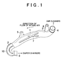
FIG. 1 is a perspective view of an inlet pipe of one embodiment of the present invention; -
FIG. 2 is a sectional view illustrating a curved portion of the inlet pipe of the embodiment in a magnified manner; -
FIGS. 3A and 3B are perspective views each schematically illustrating a molding method of the inlet pipe of the embodiment; and -
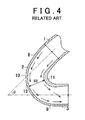
FIG. 4 is a sectional view schematically illustrating an airflow flowing inside a curved portion molded by blow molding as a related art. - One embodiment of an inlet pipe and a molding method of the inlet pipe is described below with reference to
FIGS. 1 to 4 . As illustrated inFIG. 1 , the inlet pipe is a generally cylindrical pipe in which both ends are opened. The inlet pipe is constituted by: anupstream pipe portion 1 placed on an upstream side (on the right side inFIG. 1 ) in a flow direction of intake air; and adownstream pipe portion 2 placed on a downstream side (on the left side inFIG. 1 ) in the flow direction of the intake air. - The
downstream pipe portion 2 is made of flexible resin having elasticity. Thedownstream pipe portion 2 includes anopening 3 in its end on an intake-air downstream side. Theopening 3 is connected, for example, to a super charger. - Meanwhile, the
upstream pipe portion 1 is made of rigid resin that is harder than the resin forming thedownstream pipe portion 2. Theupstream pipe portion 1 includes anopening 4 that is opened on the upstream side in the flow direction of the intake air. Theopening 4 is connected, for example, to an air cleaner. Further, theupstream pipe portion 1 is provided with twoflanges 5 projecting from theupstream pipe portion 1. Each of theflanges 5 is provided with anattachment hole 6, so that the inlet pipe is fastened to the internal combustion engine with a bolt passing through theattachment hole 6. Note that theupstream pipe portion 1 is provided with tworibs 7 that cross each other and are provided on an outer peripheral surface of theupstream pipe portion 1. Theupstream pipe portion 1 has a curved shape in accordance with positions and the like of other components attached to the internal combustion engine. - Next will be described the
downstream pipe portion 2 with reference toFIG. 2 . As illustrated inFIG. 2 , thedownstream pipe portion 2 includes: anupstream pipe 8 connected to theupstream pipe portion 1; and a downstream pipe 9 connected to the super charger on the intake-air downstream side. Theupstream pipe 8 and the downstream pipe 9 are connected to each other so that they form an acute angle. That is, thedownstream pipe portion 2 includes acurved portion 10 that is curved so that an angle θ is 90° or less where the angle θ is formed by that drawing direction of theupstream pipe 8 which is indicated by an alternate long and short dash line inFIG. 2 and that drawing direction of the downstream pipe 9 which is indicated by an alternate long and two short dashes line inFIG. 2 . - In the meantime, although the
upstream pipe portion 1 is provided with a curved portion having a small curvature, theupstream pipe portion 1 is not provided with a curved portion like thecurved portion 10 provided in thedownstream pipe portion 2. Theupstream pipe portion 1 illustrated inFIG. 2 in the present embodiment is not provided with such a portion in which an angle θ formed by an upstream pipe and a downstream pipe in the inlet pipe becomes an acute angle. Because of this, in the inlet pipe of the present embodiment illustrated inFIG. 1 , thatcurved portion 10 of thedownstream pipe portion 2 in which the angle θ formed by theupstream pipe 8 and the downstream pipe 9 in the inlet pipe is an acute angle corresponds to that part of the inlet pipe which has a large curvature, and also corresponds to that part of the inlet pipe which has a largest curvature shown inFIG. 2 . - With reference to
FIGS. 3A, 3B , the following describes a molding method of the inlet pipe. As illustrated inFIG. 3A , at the time when the inlet pipe is molded, theupstream pipe portion 1 and thedownstream pipe portion 2 are first molded separately. Thedownstream pipe portion 2 is molded by use of an outer die and a core by injection molding using flexible resin having elasticity so that a wall thickness of thedownstream pipe portion 2 has a desired thickness. Further, theupstream pipe portion 1 is molded integrally with theflanges 5 and theribs 7 by blow molding using rigid resin harder than the flexible resin. - After that, as illustrated in
FIG. 3B , theupstream pipe portion 1 and thedownstream pipe portion 2 are welded in a state where theupstream pipe portion 1 and thedownstream pipe portion 2 are positioned at predetermined relative positions, so that theupstream pipe portion 1 is connected to thedownstream pipe portion 2. - Next will be described operations of the inlet pipe according to the present embodiment and the molding method of the inlet pipe, with reference to
FIGS. 2 and4 . As illustrated inFIG. 4 , in a case where a whole inlet pipe is manufactured by blow molding such that the whole inlet pipe is molded only by an outer die, acurved portion 10 of adownstream pipe portion 2 may have a thick wall thickness in aninner part 11 having a large curvature. When the wall thickness of theinner part 11 of thecurved portion 10 is thick as such, a passage sectional area S2 at thecurved portion 10 becomes smaller than passage sectional areas of the other parts of thecurved portion 10, which makes it hard for the air to flow inside thecurved portion 10. Further, as illustrated by arrows inFIG. 4 , when the air passes through the part having a small passage sectional area, a flow speed of the air is increased. Accordingly, the air flowing inside the inlet pipe is separated from a wall surface of theinner part 11 of thecurved portion 10, so that its airflow is easy to be disturbed. Particularly, in a case where an angle θ formed by a drawing direction (an alternate long and short dash line inFIG. 4 ) of anupstream pipe 8 of thecurved portion 10 of the inlet pipe and a drawing direction (an alternate long and two short dashes line inFIG. 4 ) of a downstream pipe 9 thereof is an acute angle of 90° or less, a direction of the airflow flowing inside the inlet pipe is largely changed at thecurved portion 10. This further easily causes the airflow to be separated. - Further, in the blow molding, the molding is performed only by the outer die, so it is difficult to control roughness of an inner surface of the inlet pipe. Because of this, when the flow speed of the air flowing inside the inlet pipe is large, the airflow is disturbed due to the roughness of the inner surface of the inlet pipe, and a pressure loss of the inlet pipe might be further increased.
- Accordingly, in a case where the whole inlet pipe is manufactured by the blow molding, the pressure loss might be increased. In the meantime, as illustrated in
FIG. 2 , in the present embodiment, thedownstream pipe portion 2 including thecurved portion 10 having a largest curvature in the inlet pipe is molded by the injection molding. In the injection molding, the wall thickness can be adjusted with accuracy by adjusting a magnitude of a gap between the outer die and the core. Accordingly, thecurved portion 10 in thedownstream pipe portion 2 is molded so that its wall thickness is generally uniform at a desired thickness. Accordingly, as illustrated inFIG. 2 , thecurved portion 10 is configured such that aninner part 11 having a large curvature and anouter part 12 having a small curvature have generally the same wall thickness, so that a passage sectional area S1 of thecurved portion 10 is generally uniform. That is, an increase in the wall thickness of thecurved portion 10 is restrained in comparison with a case where the whole inlet pipe is molded by the blow molding as illustrated inFIG. 4 . - Further, as illustrated in
FIG. 2 , since the angle θ formed by the drawing direction (the alternate long and short dash line inFIG. 2 ) of theupstream pipe 8 of thecurved portion 10 and the drawing direction (the alternate long and two short dashes line inFIG. 2 ) of the downstream pipe 9 thereof is an acute angle of 90° or less, a direction of the airflow flowing inside the inlet pipe is largely changed at thecurved portion 10. Because of this, if the flow speed of the air is large, the airflow might be separated from the wall surface of theinner part 11 of thecurved portion 10. However, in a case where the inlet pipe is manufactured by the injection molding like the present embodiment, an increase in the wall thickness of thecurved portion 10 is restrained in comparison with a case where the whole inlet pipe is manufactured by the blow molding. Accordingly, an increase in the flow speed of the air along with a decrease in the passage sectional area is also restrained. This consequently makes it possible to restrain the airflow from being separated from the wall surface of theinner part 11 of thecurved portion 10. - Further, since the
curved portion 10 is molded by use of the core, roughness of the inner surface of thecurved portion 10 can be controlled by adjusting surface roughness of the core. Accordingly, even if the flow speed of the air passing through thecurved portion 10 is large, the disturbance of the airflow is restrained. - Further, the
downstream pipe portion 2 provided in the end of the inlet pipe is molded by use of flexible resin having elasticity. Accordingly, in a case where the inlet pipe manufactured by this molding method is connected to a super charger, it is possible to assemble the inlet pipe by elastically deforming theopening 3 of thedownstream pipe portion 2, and thus, its assembly is easily performed. Further, vibration is absorbed in thedownstream pipe portion 2 having such elasticity, so that transmission of the vibration between thedownstream pipe portion 2 and the super charger is restrained. - Meanwhile, the
upstream pipe portion 1 is molded by use of rigid resin that is harder than the resin forming thedownstream pipe portion 2. Accordingly, theupstream pipe portion 1 of the inlet pipe manufactured by this molding method is harder than thedownstream pipe portion 2, so that its durability is improved. - Further, since the
upstream pipe portion 1 includes theribs 7, its rigidity is improved. Consequently, the durability is increased still more. Note that, in a case where the whole inlet pipe having a complicated shape including theflanges 5 and theribs 7 is manufactured by the injection molding, the number of dies is increased in comparison with the blow molding, which may increase manufacturing cost and the number of manufacturing processes. In this regard, in the present embodiment, theupstream pipe portion 1 is manufactured by the blow molding, so that it is possible to achieve a reduction in the manufacturing cost and a decrease in the number of the manufacturing processes. - According to the above embodiment described above, it is possible to obtain the following effects. (1) The
downstream pipe portion 2 including thecurved portion 10 having a largest curvature in the inlet pipe is molded by the injection molding. This makes it possible to restrain a decrease in the passage sectional area due to an increase in the wall thickness of thecurved portion 10. Further, it is possible to restrain the airflow from being separated from the wall surface of theinner part 11 of thecurved portion 10. Moreover, it is possible to restrain an increase in the pressure loss caused due to the roughness of the inner surface. Accordingly, the pressure loss of the inlet pipe can be restrained. - (2) The
downstream pipe portion 2 is molded by use of flexible resin having elasticity, and theupstream pipe portion 1 is molded by use of rigid resin harder than thedownstream pipe portion 2. Accordingly, the assembly to other components can be performed easily while the durability of the inlet pipe is secured. Further, the transmission of vibration can be also restrained. - Note that the above embodiment can be modified as follows.
- The above embodiment shows an example in which the
downstream pipe portion 2 includes onecurved portion 10 having a largest curvature. However, asModification 1 of the present embodiment, thedownstream pipe portion 2 may include a plurality of curved portions having a large curvature. Even with such a configuration, it is possible to yield the same effects as the effects (1) and (2). - Further, in such a configuration, among the curved portions in the inlet pipe, not only the curved portion having the largest curvature, but also a curved portion having a curvature of greater than a predetermined value may be molded by the injection molding, as
Modification 2 of the present embodiment. Note that it is desirable that the predetermined value be a smallest value among curvatures of curved portions that might cause an increase in a pressure loss, when the curved portions are molded by the blow molding. According to this configuration, the pressure loss of the inlet pipe can be further restrained. - In the above embodiment, the
upstream pipe portion 1 is connected to thedownstream pipe portion 2 by welding. However, asModification 3 of the present embodiment, a connection method of them may be other methods including a method to adhere them by use of an adhesive. - In addition to
Modifications 1 to 3, the following modifications may be employed. That is, theflanges 5 and theribs 7 may not be molded with theupstream pipe portion 1 by the blow molding. For example, after theupstream pipe portion 1 is molded by the blow molding, theflanges 5 and theribs 7 may be adhered to theupstream pipe portion 1. Alternatively, theflanges 5 and theribs 7 may not be provided in theupstream pipe portion 1. - The above embodiment deals with an example in which the
downstream pipe portion 2 is provided with thecurved portion 10 having a largest curvature. However, thecurved portion 10 may be provided in theupstream pipe portion 1. In this case, that part of theupstream pipe portion 1 which is provided with the curved portion may be molded by the injection molding, and the other part except the part molded by the injection molding may be molded by the blow molding. Even with such a configuration, it is possible to yield the same effect as the effect (1). - The
opening 4 of theupstream pipe portion 1 may be molded by use of resin having elasticity, and the other part of theupstream pipe portion 1 except theopening 4 may be molded by use of resin harder than theopening 4. According to such a configuration, it is possible to further easily assemble the inlet pipe to the air cleaner. That is, if the openings provided at both ends of the inlet pipe are molded by use of resin having elasticity, it is possible to easily assemble the inlet pipe. - In the above embodiment, the
downstream pipe portion 2 is molded by use of flexible resin having elasticity, and theupstream pipe portion 1 is molded by use of rigid resin harder than the flexible resin forming thedownstream pipe portion 2. However, theupstream pipe portion 1 may be molded by use of resin having hardness equivalent to the flexible resin forming thedownstream pipe portion 2, or by use of resin softer than the resin forming thedownstream pipe portion 2. Even with such a configuration, it is still possible to yield the same effect as the effect (1). - In the above embodiment, the
downstream pipe portion 2 is molded by use of flexible resin having elasticity, but such a configuration may be omitted. For example, the whole inlet pipe may be molded by use of rigid resin. - The above embodiment deals with, as an example, such a configuration that, in the
curved portion 10 of thedownstream pipe portion 2, the angle θ formed by theupstream pipe 8 and the downstream pipe 9 is an acute angle. However, the same configuration as above may be applied to a case where the angle θ formed by theupstream pipe 8 and the downstream pipe 9 is an obtuse angle. That is, even in a case where the angle θ of thecurved portion 10 is an obtuse angle, if the curvature of thecurved portion 10 is largest and a pressure loss might be increased on the occasion of molding thecurved portion 10 by the blow molding, the curved portion may be molded by the injection molding. - Provided are an inlet pipe including a curved portion (10) having a curved shape, and a molding method thereof. In the molding method of the inlet pipe, the inlet pipe having a curved shape is molded by a step of molding, by injection molding, a downstream pipe portion (2) including a curved portion (10) having a large curvature, and a step of molding an upstream pipe portion (1) by blow molding.
Claims (8)
- A molding method of an inlet pipe including a curved portion (10) having a curved shape, the molding method characterized by comprising:molding one part (2) of the inlet pipe by injection molding, the one part (2) including the curved portion (10) having a largest curvature; andmolding, by blow molding, the other part (1) of the inlet pipe except the one part (2) molded by the injection molding.
- The molding method of the inlet pipe, according to claim 1, characterized in that
the one part (2) of the inlet pipe is molded by the injection molding, in the one part (2) the curved portion (10) having a curvature of greater than a predetermined value, and
the other part (1) of the inlet pipe is molded by the blow molding, the other part (1) having a curvature of the predetermined value or less. - The molding method of the inlet pipe, according to claim 1, characterized in that
the curved portion (10) having the largest curvature is a curved portion (10) configured to connect, at an acute angle, a pipe connected to an upstream side and a pipe connected to a downstream side,
the one part (2) of the inlet pipe is molded by the injection molding, the one part (2) including the curved portion (10), and
the other part (1) of the inlet pipe is molded by the blow molding, the other part (1) a part being except the one part (2) molded by the injection molding. - The molding method of the inlet pipe, according to any one of claims 1 through 3, characterized in that
the injection molding is performed by use of resin having elasticity, and
the blow molding is performed by use of resin harder than the resin having elasticity. - An inlet pipe including a curved portion (10) having a curved shape, the inlet pipe characterized by comprising
one part (2) of the inlet pipe including a curved portion (10) having a largest curvature, the one part (2) of the inlet pipe molded by injection molding, and
the other part (1) of the inlet pipe that is a part except the one part molded by the injection molding, the other part (1) of the inlet pipe being molded by blow molding. - The inlet pipe according to claim 5, characterized in that
the one part (2) of the inlet pipe is molded by the injection molding, in the one part (2) the curved portion (10) having a curvature of greater than a predetermined value, and the other part (1) of the inlet pipe is molded by the blow molding. - The inlet pipe according to claim 5 or 6, characterized in that
the one part (2) of the inlet pipe molded by the injection molding is made of resin having elasticity, and
the other part (1) of the inlet pipe molded by the blow molding is made of resin harder than the resin having elasticity. - The inlet pipe according to claim 5 or 7, characterized in that
the one part (2) of the inlet pipe molded by the injection molding includes the curved portion (10) curved so as to connect, at an acute angle, a pipe connected to an upstream side and a pipe connected to a downstream side.
Applications Claiming Priority (1)
| Application Number | Priority Date | Filing Date | Title |
|---|---|---|---|
| JP2014039724A JP5949809B2 (en) | 2014-02-28 | 2014-02-28 | Intake pipe and method of forming intake pipe |
Publications (1)
| Publication Number | Publication Date |
|---|---|
| EP2915653A1 true EP2915653A1 (en) | 2015-09-09 |
Family
ID=52633088
Family Applications (1)
| Application Number | Title | Priority Date | Filing Date |
|---|---|---|---|
| EP15156669.2A Withdrawn EP2915653A1 (en) | 2014-02-28 | 2015-02-26 | Inlet pipe and molding method of inlet pipe |
Country Status (5)
| Country | Link |
|---|---|
| US (1) | US9789635B2 (en) |
| EP (1) | EP2915653A1 (en) |
| JP (1) | JP5949809B2 (en) |
| CN (1) | CN104875360B (en) |
| BR (1) | BR102015004027A2 (en) |
Families Citing this family (4)
| Publication number | Priority date | Publication date | Assignee | Title |
|---|---|---|---|---|
| JP6373238B2 (en) | 2015-08-21 | 2018-08-15 | 双葉電子工業株式会社 | Detection device, flying object, control device, airflow detection method |
| JP7287261B2 (en) * | 2019-12-18 | 2023-06-06 | トヨタ紡織株式会社 | intake duct |
| CN111531850A (en) * | 2020-03-31 | 2020-08-14 | 浙江峻和科技股份有限公司 | Automobile intercooler air inlet pipe, blow molding die of automobile intercooler air inlet pipe and production process of automobile intercooler air inlet pipe |
| USD1100981S1 (en) * | 2023-05-17 | 2025-11-04 | Prl Performance, Llc | Turbocharger inlet pipe |
Citations (9)
| Publication number | Priority date | Publication date | Assignee | Title |
|---|---|---|---|---|
| JPS6095178A (en) * | 1983-10-31 | 1985-05-28 | Isuzu Motors Ltd | Internal-combustion engine using duct of resin compounding calcium carbonate in intake system |
| US5266262A (en) * | 1991-07-19 | 1993-11-30 | Mitoyo Resin Co. Ltd. | Method for injection molding a large thickness flange at end of blow molding tube |
| JPH0835458A (en) * | 1993-10-04 | 1996-02-06 | Calsonic Corp | Synthetic resin intake pipe for engine and manufacture thereof |
| DE19613467A1 (en) * | 1996-04-04 | 1997-10-09 | Mann & Hummel Filter | Intake system for an internal combustion engine |
| DE19909850A1 (en) * | 1999-03-08 | 2000-09-14 | Mahle Filtersysteme Gmbh | Suction system for an internal combustion engine |
| US6475424B1 (en) * | 1998-05-14 | 2002-11-05 | Cambridge Industries, Inc. | Multi-process molding method and article produced by same |
| DE102008019577A1 (en) * | 2008-04-18 | 2009-10-22 | Veritas Ag | Fluid pipe i.e. charge air pipe, manufacturing method, involves blow-molding of pipe blank with intervention of functional section so that functional sections are kept undeformed |
| US20130146170A1 (en) * | 2011-12-07 | 2013-06-13 | Hyundai Motor Company | Air intake hose for vehicle and production method thereof |
| CN203214202U (en) * | 2013-04-15 | 2013-09-25 | 宁波博纳汽车零部件有限公司 | Integrated type turbocharger air inlet plastic tube |
Family Cites Families (10)
| Publication number | Priority date | Publication date | Assignee | Title |
|---|---|---|---|---|
| US3262719A (en) * | 1965-10-19 | 1966-07-26 | United Aircraft Corp | Self-welded flexible joints |
| AT337334B (en) * | 1973-09-18 | 1977-06-27 | Steag Ag | IMPACT ELBOW FOR DUST LINES |
| US4410281A (en) * | 1981-03-02 | 1983-10-18 | Ralph B. Carter Company | Mixing method and apparatus utilizing pipe elbows |
| JPS60183265U (en) | 1984-05-16 | 1985-12-05 | カルソニックカンセイ株式会社 | Synthetic resin intake manifold |
| US4822080A (en) * | 1987-04-02 | 1989-04-18 | Darish Joseph J | Rotatably adjustable pipe joint/coupling seal |
| US5409066A (en) * | 1990-05-03 | 1995-04-25 | Agf Manufacturing, Inc. | Adjustable sprinkler head positioning assembly |
| JP3308565B2 (en) | 1991-07-29 | 2002-07-29 | カルソニックカンセイ株式会社 | Manufacturing method of engine intake system parts |
| US5529084A (en) * | 1994-03-24 | 1996-06-25 | Koch Engineering Company, Inc. | Laminar flow elbow system and method |
| JP3844191B2 (en) * | 2000-09-29 | 2006-11-08 | 豊田合成株式会社 | Intake duct and manufacturing method thereof |
| JP2007038689A (en) * | 2006-11-03 | 2007-02-15 | Aitec:Kk | Manufacturing process of resonator |
-
2014
- 2014-02-28 JP JP2014039724A patent/JP5949809B2/en active Active
-
2015
- 2015-02-19 US US14/626,196 patent/US9789635B2/en active Active
- 2015-02-25 BR BR102015004027A patent/BR102015004027A2/en not_active Application Discontinuation
- 2015-02-26 CN CN201510088104.7A patent/CN104875360B/en not_active Expired - Fee Related
- 2015-02-26 EP EP15156669.2A patent/EP2915653A1/en not_active Withdrawn
Patent Citations (10)
| Publication number | Priority date | Publication date | Assignee | Title |
|---|---|---|---|---|
| JPS6095178A (en) * | 1983-10-31 | 1985-05-28 | Isuzu Motors Ltd | Internal-combustion engine using duct of resin compounding calcium carbonate in intake system |
| US5266262A (en) * | 1991-07-19 | 1993-11-30 | Mitoyo Resin Co. Ltd. | Method for injection molding a large thickness flange at end of blow molding tube |
| JPH0835458A (en) * | 1993-10-04 | 1996-02-06 | Calsonic Corp | Synthetic resin intake pipe for engine and manufacture thereof |
| DE19613467A1 (en) * | 1996-04-04 | 1997-10-09 | Mann & Hummel Filter | Intake system for an internal combustion engine |
| JP2000508397A (en) | 1996-04-04 | 2000-07-04 | フイルテルウエルク マン ウント フンメル ゲゼルシヤフト ミツト ベシユレンクテル ハフツング | Intake mechanism for internal combustion engine |
| US6475424B1 (en) * | 1998-05-14 | 2002-11-05 | Cambridge Industries, Inc. | Multi-process molding method and article produced by same |
| DE19909850A1 (en) * | 1999-03-08 | 2000-09-14 | Mahle Filtersysteme Gmbh | Suction system for an internal combustion engine |
| DE102008019577A1 (en) * | 2008-04-18 | 2009-10-22 | Veritas Ag | Fluid pipe i.e. charge air pipe, manufacturing method, involves blow-molding of pipe blank with intervention of functional section so that functional sections are kept undeformed |
| US20130146170A1 (en) * | 2011-12-07 | 2013-06-13 | Hyundai Motor Company | Air intake hose for vehicle and production method thereof |
| CN203214202U (en) * | 2013-04-15 | 2013-09-25 | 宁波博纳汽车零部件有限公司 | Integrated type turbocharger air inlet plastic tube |
Non-Patent Citations (1)
| Title |
|---|
| ANONYMOUS: "Pipe | Definition of Pipe by Merriam-Webster", 19 March 2019 (2019-03-19), XP055571474, Retrieved from the Internet <URL:https://www.merriam-webster.com/dictionary/pipe> [retrieved on 20190319] * |
Also Published As
| Publication number | Publication date |
|---|---|
| JP2015163780A (en) | 2015-09-10 |
| BR102015004027A2 (en) | 2015-12-15 |
| US9789635B2 (en) | 2017-10-17 |
| CN104875360A (en) | 2015-09-02 |
| US20150246467A1 (en) | 2015-09-03 |
| JP5949809B2 (en) | 2016-07-13 |
| CN104875360B (en) | 2017-11-10 |
Similar Documents
| Publication | Publication Date | Title |
|---|---|---|
| US9789635B2 (en) | Inlet pipe and molding method of inlet pipe | |
| US20080233856A1 (en) | Air conditioner duct | |
| JP6066698B2 (en) | Fastening structure of resin parts and molding apparatus therefor | |
| EP3056723A1 (en) | Intake noise reducing apparatus for internal combustion engine | |
| US7896402B2 (en) | Spacer for coaxially sheathed fuel pipes | |
| JP4729442B2 (en) | Flow rate measuring device, flow rate measuring passage and manufacturing method thereof | |
| JP3975980B2 (en) | Engine intake system | |
| JP5340816B2 (en) | Ventilation duct | |
| CN108167376B (en) | Dynamic vibration absorber | |
| JP4928135B2 (en) | Intake device and intake manifold of internal combustion engine | |
| JP2009299589A (en) | Intake system component | |
| JP4853423B2 (en) | Manufacturing method of air conditioning duct | |
| EP3205872A1 (en) | Intake noise reduction device | |
| JP2011074862A (en) | Intake manifold | |
| US9145997B2 (en) | Mold for making sound-absorbing duct and sound-absorbing duct using the same | |
| KR101814468B1 (en) | Reinforcement structure and hose including reinforcement structure | |
| US8091586B2 (en) | Method of manufacturing a venturi tube for a fuel system | |
| JP2007263214A (en) | Suction hose | |
| CN211599867U (en) | Joint member | |
| JP6218644B2 (en) | Manufacturing method of intake device | |
| JP4866387B2 (en) | Manufacturing method of resin intake manifold | |
| JP5912013B2 (en) | Resin intake manifold | |
| JP5465144B2 (en) | Intake device | |
| JP4906543B2 (en) | Hose with clamp | |
| JP4519103B2 (en) | Resin throttle body |
Legal Events
| Date | Code | Title | Description |
|---|---|---|---|
| PUAI | Public reference made under article 153(3) epc to a published international application that has entered the european phase |
Free format text: ORIGINAL CODE: 0009012 |
|
| 17P | Request for examination filed |
Effective date: 20150226 |
|
| AK | Designated contracting states |
Kind code of ref document: A1 Designated state(s): AL AT BE BG CH CY CZ DE DK EE ES FI FR GB GR HR HU IE IS IT LI LT LU LV MC MK MT NL NO PL PT RO RS SE SI SK SM TR |
|
| AX | Request for extension of the european patent |
Extension state: BA ME |
|
| 17Q | First examination report despatched |
Effective date: 20190402 |
|
| STAA | Information on the status of an ep patent application or granted ep patent |
Free format text: STATUS: THE APPLICATION HAS BEEN WITHDRAWN |
|
| 18W | Application withdrawn |
Effective date: 20190730 |