EP2915496B2 - Implantable device - Google Patents
Implantable device Download PDFInfo
- Publication number
- EP2915496B2 EP2915496B2 EP14158156.1A EP14158156A EP2915496B2 EP 2915496 B2 EP2915496 B2 EP 2915496B2 EP 14158156 A EP14158156 A EP 14158156A EP 2915496 B2 EP2915496 B2 EP 2915496B2
- Authority
- EP
- European Patent Office
- Prior art keywords
- distractor
- implantable
- intramedullary
- implantable intramedullary
- actuator
- Prior art date
- Legal status (The legal status is an assumption and is not a legal conclusion. Google has not performed a legal analysis and makes no representation as to the accuracy of the status listed.)
- Active
Links
Images
Classifications
-
- A—HUMAN NECESSITIES
- A61—MEDICAL OR VETERINARY SCIENCE; HYGIENE
- A61B—DIAGNOSIS; SURGERY; IDENTIFICATION
- A61B17/00—Surgical instruments, devices or methods
- A61B17/56—Surgical instruments or methods for treatment of bones or joints; Devices specially adapted therefor
- A61B17/58—Surgical instruments or methods for treatment of bones or joints; Devices specially adapted therefor for osteosynthesis, e.g. bone plates, screws or setting implements
- A61B17/60—Surgical instruments or methods for treatment of bones or joints; Devices specially adapted therefor for osteosynthesis, e.g. bone plates, screws or setting implements for external osteosynthesis, e.g. distractors, contractors
-
- A—HUMAN NECESSITIES
- A61—MEDICAL OR VETERINARY SCIENCE; HYGIENE
- A61B—DIAGNOSIS; SURGERY; IDENTIFICATION
- A61B17/00—Surgical instruments, devices or methods
- A61B17/56—Surgical instruments or methods for treatment of bones or joints; Devices specially adapted therefor
- A61B17/58—Surgical instruments or methods for treatment of bones or joints; Devices specially adapted therefor for osteosynthesis, e.g. bone plates, screws or setting implements
- A61B17/68—Internal fixation devices, including fasteners and spinal fixators, even if a part thereof projects from the skin
- A61B17/70—Spinal positioners or stabilisers, e.g. stabilisers comprising fluid filler in an implant
- A61B17/7001—Screws or hooks combined with longitudinal elements which do not contact vertebrae
- A61B17/7002—Longitudinal elements, e.g. rods
- A61B17/7014—Longitudinal elements, e.g. rods with means for adjusting the distance between two screws or hooks
- A61B17/7016—Longitudinal elements, e.g. rods with means for adjusting the distance between two screws or hooks electric or electromagnetic means
-
- A—HUMAN NECESSITIES
- A61—MEDICAL OR VETERINARY SCIENCE; HYGIENE
- A61B—DIAGNOSIS; SURGERY; IDENTIFICATION
- A61B17/00—Surgical instruments, devices or methods
- A61B17/56—Surgical instruments or methods for treatment of bones or joints; Devices specially adapted therefor
- A61B17/58—Surgical instruments or methods for treatment of bones or joints; Devices specially adapted therefor for osteosynthesis, e.g. bone plates, screws or setting implements
- A61B17/68—Internal fixation devices, including fasteners and spinal fixators, even if a part thereof projects from the skin
- A61B17/72—Intramedullary devices, e.g. pins or nails
- A61B17/7216—Intramedullary devices, e.g. pins or nails for bone lengthening or compression
-
- A—HUMAN NECESSITIES
- A61—MEDICAL OR VETERINARY SCIENCE; HYGIENE
- A61B—DIAGNOSIS; SURGERY; IDENTIFICATION
- A61B17/00—Surgical instruments, devices or methods
- A61B17/56—Surgical instruments or methods for treatment of bones or joints; Devices specially adapted therefor
- A61B17/58—Surgical instruments or methods for treatment of bones or joints; Devices specially adapted therefor for osteosynthesis, e.g. bone plates, screws or setting implements
- A61B17/68—Internal fixation devices, including fasteners and spinal fixators, even if a part thereof projects from the skin
- A61B17/72—Intramedullary devices, e.g. pins or nails
- A61B17/7216—Intramedullary devices, e.g. pins or nails for bone lengthening or compression
- A61B17/7225—Intramedullary devices, e.g. pins or nails for bone lengthening or compression for bone compression
-
- A—HUMAN NECESSITIES
- A61—MEDICAL OR VETERINARY SCIENCE; HYGIENE
- A61B—DIAGNOSIS; SURGERY; IDENTIFICATION
- A61B17/00—Surgical instruments, devices or methods
- A61B17/56—Surgical instruments or methods for treatment of bones or joints; Devices specially adapted therefor
- A61B17/58—Surgical instruments or methods for treatment of bones or joints; Devices specially adapted therefor for osteosynthesis, e.g. bone plates, screws or setting implements
- A61B17/68—Internal fixation devices, including fasteners and spinal fixators, even if a part thereof projects from the skin
- A61B17/80—Cortical plates, i.e. bone plates; Instruments for holding or positioning cortical plates, or for compressing bones attached to cortical plates
- A61B17/8004—Cortical plates, i.e. bone plates; Instruments for holding or positioning cortical plates, or for compressing bones attached to cortical plates with means for distracting or compressing the bone or bones
-
- A—HUMAN NECESSITIES
- A61—MEDICAL OR VETERINARY SCIENCE; HYGIENE
- A61B—DIAGNOSIS; SURGERY; IDENTIFICATION
- A61B17/00—Surgical instruments, devices or methods
- A61B17/56—Surgical instruments or methods for treatment of bones or joints; Devices specially adapted therefor
- A61B17/58—Surgical instruments or methods for treatment of bones or joints; Devices specially adapted therefor for osteosynthesis, e.g. bone plates, screws or setting implements
- A61B17/88—Osteosynthesis instruments; Methods or means for implanting or extracting internal or external fixation devices
- A61B17/885—Tools for expanding or compacting bones or discs or cavities therein
- A61B17/8852—Tools for expanding or compacting bones or discs or cavities therein capable of being assembled or enlarged, or changing shape, inside the bone or disc
- A61B17/8858—Tools for expanding or compacting bones or discs or cavities therein capable of being assembled or enlarged, or changing shape, inside the bone or disc laterally or radially expansible
-
- A—HUMAN NECESSITIES
- A61—MEDICAL OR VETERINARY SCIENCE; HYGIENE
- A61B—DIAGNOSIS; SURGERY; IDENTIFICATION
- A61B17/00—Surgical instruments, devices or methods
- A61B17/56—Surgical instruments or methods for treatment of bones or joints; Devices specially adapted therefor
- A61B17/58—Surgical instruments or methods for treatment of bones or joints; Devices specially adapted therefor for osteosynthesis, e.g. bone plates, screws or setting implements
- A61B17/60—Surgical instruments or methods for treatment of bones or joints; Devices specially adapted therefor for osteosynthesis, e.g. bone plates, screws or setting implements for external osteosynthesis, e.g. distractors, contractors
- A61B17/66—Alignment, compression or distraction mechanisms
- A61B17/663—Alignment, compression or distraction mechanisms for jaw bones, e.g. subcutaneous distractors with external access
-
- A—HUMAN NECESSITIES
- A61—MEDICAL OR VETERINARY SCIENCE; HYGIENE
- A61B—DIAGNOSIS; SURGERY; IDENTIFICATION
- A61B17/00—Surgical instruments, devices or methods
- A61B2017/00017—Electrical control of surgical instruments
- A61B2017/00212—Electrical control of surgical instruments using remote controls
-
- A—HUMAN NECESSITIES
- A61—MEDICAL OR VETERINARY SCIENCE; HYGIENE
- A61B—DIAGNOSIS; SURGERY; IDENTIFICATION
- A61B17/00—Surgical instruments, devices or methods
- A61B2017/00017—Electrical control of surgical instruments
- A61B2017/00221—Electrical control of surgical instruments with wireless transmission of data, e.g. by infrared radiation or radiowaves
-
- A—HUMAN NECESSITIES
- A61—MEDICAL OR VETERINARY SCIENCE; HYGIENE
- A61B—DIAGNOSIS; SURGERY; IDENTIFICATION
- A61B17/00—Surgical instruments, devices or methods
- A61B2017/00367—Details of actuation of instruments, e.g. relations between pushing buttons, or the like, and activation of the tool, working tip, or the like
- A61B2017/00398—Details of actuation of instruments, e.g. relations between pushing buttons, or the like, and activation of the tool, working tip, or the like using powered actuators, e.g. stepper motors, solenoids
-
- A—HUMAN NECESSITIES
- A61—MEDICAL OR VETERINARY SCIENCE; HYGIENE
- A61B—DIAGNOSIS; SURGERY; IDENTIFICATION
- A61B17/00—Surgical instruments, devices or methods
- A61B2017/00367—Details of actuation of instruments, e.g. relations between pushing buttons, or the like, and activation of the tool, working tip, or the like
- A61B2017/00411—Details of actuation of instruments, e.g. relations between pushing buttons, or the like, and activation of the tool, working tip, or the like actuated by application of energy from an energy source outside the body
-
- A—HUMAN NECESSITIES
- A61—MEDICAL OR VETERINARY SCIENCE; HYGIENE
- A61B—DIAGNOSIS; SURGERY; IDENTIFICATION
- A61B17/00—Surgical instruments, devices or methods
- A61B2017/00681—Aspects not otherwise provided for
- A61B2017/00734—Aspects not otherwise provided for battery operated
-
- A—HUMAN NECESSITIES
- A61—MEDICAL OR VETERINARY SCIENCE; HYGIENE
- A61B—DIAGNOSIS; SURGERY; IDENTIFICATION
- A61B17/00—Surgical instruments, devices or methods
- A61B17/02—Surgical instruments, devices or methods for holding wounds open, e.g. retractors; Tractors
- A61B17/025—Joint distractors
- A61B2017/0256—Joint distractors for the spine
-
- A—HUMAN NECESSITIES
- A61—MEDICAL OR VETERINARY SCIENCE; HYGIENE
- A61M—DEVICES FOR INTRODUCING MEDIA INTO, OR ONTO, THE BODY; DEVICES FOR TRANSDUCING BODY MEDIA OR FOR TAKING MEDIA FROM THE BODY; DEVICES FOR PRODUCING OR ENDING SLEEP OR STUPOR
- A61M5/00—Devices for bringing media into the body in a subcutaneous, intra-vascular or intramuscular way; Accessories therefor, e.g. filling or cleaning devices, arm-rests
- A61M5/14—Infusion devices, e.g. infusing by gravity; Blood infusion; Accessories therefor
- A61M5/142—Pressure infusion, e.g. using pumps
- A61M5/14244—Pressure infusion, e.g. using pumps adapted to be carried by the patient, e.g. portable on the body
- A61M5/14276—Pressure infusion, e.g. using pumps adapted to be carried by the patient, e.g. portable on the body specially adapted for implantation
Definitions
- Orthopaedic distractors find application in the therapy of a plurality of diseases and malformations, in particular, but not exclusively, in the extension of long bones, but also in the surgical therapy of the spine, the jawbone, or other skeletal districts.
- Such techniques employ external distractor devices fixed on the bone and, more and more, internal devices that are fully implanted in the body, for example centromedullary distractor nails for the extension of long bones, jack distractors for the spine therapy, and other specialized forms of active implants.
- biocompatible implantable device that comprises a mechanical actuator and can operate without relying on external elements or power sources.
- the present invention is an intramedullary nail distractor for the correction of length deficit in long bones, like for example the femur, tibia, humerus, or any other long bone.
- a possible therapy for such conditions comprises the surgically insertion in the medullary cavity of the target bone of a distracting nail comprising an actuator that allows to modify its overall length, and that can exert a sufficient linear force so as to promote bone growth on both sides of an artificial fracture line.
- the implant is operated during a n extended time period according to a specified elongation plan and is usually left in place, as a passive structural intramedullary nail, once the bone has reached the desired length.
- the relative linear speed of the connecting ends 31 and 61 are of the order of some millimetre per day.
- the implantable device comprises a driving unit 25 and a kinematic assembly 27 coaxially joined together: the driving unit 25 is placed at one extremity of the intramedullary nail, and includes an electric motor 35 that can be set into rotation by a command unit, not visible in the figure, and a source of electrical energy 32, for example a stack of lithium cells or another suitable primary or secondary (rechargeable) electrical battery.
- the driving unit 25 is placed at one extremity of the intramedullary nail, and includes an electric motor 35 that can be set into rotation by a command unit, not visible in the figure, and a source of electrical energy 32, for example a stack of lithium cells or another suitable primary or secondary (rechargeable) electrical battery.
- the driving unit 25 is fully enclosed into a hermetic capsule 20, for example made of titanium, PEEK, or of any suitable biocompatible material.
- the purpose of the capsule is to prevent the ingress of body fluids into the space that encloses the electronics, the electric motor, and the battery, and effectively prevent any contact between these component and body tissue.
- the capsule is hermetically sealed or welded and does not present any opening so as to guarantee containment for an essentially indefinite time. More preferably, the whole driving unit is contained in a double sealed capsule so as to prevent any contamination.
- the battery pack may be contained in a separate hermetic capsule distinct from that that encloses the motor 35, and the capsule have pass-through electric connectors to allow the transmission of electric energy from one to the other.
- the implantable device may be entirely dependent from the external energy supply for its functioning, or include a rechargeable accumulator that can be replenished by the external energy source.
- Wireless energy transmission could be obtained by electric or magnetic induction, or by an ultrasonic converter, or by any other suitable energy transmission means.
- the electric motor 35 is connected, directly or indirectly, to a first magnetic rotor 37, also comprised in the capsule 20 that presents an arrangement of alternate magnetic poles. Its rotation is transmitted, by magnetic coupling, to a second magnetic rotor 41 outside the capsule 20, magnetically coupled to said first magnetic rotor such that it can be rotationally driven by the motor.
- Figures 2a and 2b represent a possible arrangement of such coupled rotors 37 and 41 as a pair of coaxial disks placed face to face. Alternative structures, for example with cylindrical rotors, are also possible.
- the reduction is obtained by a gearbox 45, for example a cascade of planetary reductions, and by the final lead-screw 48 and nut 49 transmission that transforms the rotary motion at the output of the gear reduction 45 into a linear motion of the plunger 60 relative to the sleeve 50.
- the reduction system of this embodiment comprising the planetary stages 45, and the lead-screw and nut assembly is not enclosed into a hermetic capsule and, therefore, it can enter in contact with body fluids, and is in fact lubricated by body fluids. Accordingly, it is integrally built with biocompatible materials like titanium, Cobalt-Chrome alloy, nitinol, stainless steel, Polyethylene, PEEK, PET, PTFE, biocompatible ceramic, or any other suitable biocompatible material.
- the reduction ratio of the gearbox 45 is comprised between 500:1 and 2000:1.
- a cascade of five 4:1 planetary stages could be used to achieve an overall reduction ratio of 1024:1.
- the lead-screw 40 could turn at about one revolution per minute.
- the reduction system could use harmonic reducers, wobbling gears, cycloidal gears, or other transmission systems achieving the desired transmission ratios.
- the distraction plan spans over a periods of several days or weeks, during which the patient is encouraged to move and exercise the treated limb.
- the gearbox 45 and the lead-screw/nut assembly 48, 49 are arranged to resist to the axial and radial loads induced by the patient's weight and motion, plus the torque transmitted during the distraction.
- this is achieved by means of biocompatible axial bearings 46 in the gearbox 45.
- the bearings have titanium cages and ceramic balls or rollers.
- FIG 2a shows, perhaps more clearly, the disposition of the magnetic rotors 37 and 41.
- Each rotor comprises a plurality of magnetized zones that define a pattern of magnetic poles having alternate polarities (represented by colour variations).
- the second rotor 41 which is not protected inside the hermetic capsule 20, has preferably the magnetic materials covered by a protective biocompatible material (not visible).
- the motor 35 in the hermetic capsule 20, the magnetic rotors 37 and 41, the reduction system 45, the lead-screw 48, and the nut 49 are all coaxially aligned and each element is directly connected to the following one, thus, the transmission is efficient and compact.
- the actuator is wholly contained in the implantable nail, and does not rely on external sources of energy or pressurised fluids for its operation.
- Another advantageous feature is that the whole transmission chain is reversible, in the sense that the linear relative motion of the attachment points 61 and 31 can be in both directions, either lengthening or shortening the implantable nail. Thanks to this feature that the distraction can be reversed, if needed.
- the driving unit also comprises a remotely-controllable command circuit that determines the rotation or the stop of the motor 35.
- the motor can be operated after the implantation, based on a predetermined post-operatory plan and/or on clinical and X-ray observations.
- the command circuit includes magnetic field sensors, for example hall sensors. In this manner, a surgeon can control the operation of the motor 35 by placing permanent magnet at predetermined positions outside the implanted limb, preferably in this case, the command circuit has two magnetic field sensors at spaced-apart positions, one for operating the actuator in the normal, lengthening direction, and another for reversing the distraction.
- the lead-screw transmission is preferably self-locking, in the sense that the nail normally resists to axial loads without changing its length unless the electric motor is active. If needed, an active locking mechanism can be added to the implant.
- the invention admits also other forms of remote control, for example by radio transmission, near-field electromagnetic communication, ultrasounds, or any other suitable wireless communication system.
- FIGS. 1 , 2 , 3a, 3b are specially adapted for an implantation in the medullary canal of long bones.
- Figures 3a, 3b illustrate a not claimed variant of the invention applicable to other parts of the skeleton, in particular in the treatment of the spine and of scoliosis.
- the lead-screw 48 operates an articulated jack 13 that can be used as implantable spine distractor.
- Figure 4 illustrates the possible implantation of a device 15 used as a Cranio-Maxillo distractor.
- the implant is fixed outside of a bone, in this case a mandible.
- limb length correction both congenital and posttraumatic; poliomyelitis; pseudoarthrosis; bone stump extension after amputations; bone transport after tumour resection; unilateral or bilateral impaired or abnormal growth; tumour prosthetic knee; cosmetic lengthening; Orthognatic surgery; correction of jaw deformities; Craniomaxillofacial distraction; Alveolar Ridge distraction; Multi-vector distraction; and, in the spine district, non-fusion scoliosis and other orthopaedic conditions.
Landscapes
- Health & Medical Sciences (AREA)
- Orthopedic Medicine & Surgery (AREA)
- Life Sciences & Earth Sciences (AREA)
- Surgery (AREA)
- Engineering & Computer Science (AREA)
- General Health & Medical Sciences (AREA)
- Veterinary Medicine (AREA)
- Public Health (AREA)
- Nuclear Medicine, Radiotherapy & Molecular Imaging (AREA)
- Biomedical Technology (AREA)
- Heart & Thoracic Surgery (AREA)
- Medical Informatics (AREA)
- Molecular Biology (AREA)
- Animal Behavior & Ethology (AREA)
- Neurology (AREA)
- Physics & Mathematics (AREA)
- Electromagnetism (AREA)
- Prostheses (AREA)
- Surgical Instruments (AREA)
Description
- The present invention relates, in embodiments, to an implantable device comprising an autonomously supplied mechanical actuator, for example, but not exclusively, an orthopaedic distractor comprising an electrical motor in a hermetic capsule and a biocompatible transmission system arranged for bidirectional displacement of bones or skeletal elements.
- Orthopaedic distractors find application in the therapy of a plurality of diseases and malformations, in particular, but not exclusively, in the extension of long bones, but also in the surgical therapy of the spine, the jawbone, or other skeletal districts. Such techniques employ external distractor devices fixed on the bone and, more and more, internal devices that are fully implanted in the body, for example centromedullary distractor nails for the extension of long bones, jack distractors for the spine therapy, and other specialized forms of active implants.
-
FR2961386 US200629683 relates to a distractor driving a lead-screw device.WO9100065 - A problem common to these devices is that of ensuring the biocompatibility of the implant containing electric motors. These devices include in fact several materials, for example control electronics, rare-earth magnets, electric windings and magnetic circuits that must not enter in contact with body tissues. The same limitations apply also to the battery used for the energy supply.
-
-
US7753915 describes a centromedullary nail with a magnetic rotor that is driven in rotation by a rotating magnetic field generated by coils external to the body andUS2004023623 describes a distractor in which the electric motor is not implanted, but external to the body, and the motion is magnetically transmitted to an internal actuator. These devices solve the problem of enclosing the potentially non-compatible components, but are not fully contained in the body, and require a relatively bulky external part that can be a nuisance for the patient. - Other forms of implantable devices comprising electromechanical actuators are also known, for example in the form of implantable pumps for drug delivery. In these devices as well as in the electromechanical distractors separation of the electric motor, electronic units and battery pack from the body tissues is of paramount importance.
-
WO2010/061391 discloses an automatic distractor for adjusting alveolar ridge elevation or expansion distraction gap in a patient, wherein a motor and a reduction gear are enclosed in a sealed cylinder. - It is therefore an aim of the present invention to provide a biocompatible implantable device that comprises a mechanical actuator and can operate without relying on external elements or power sources.
- According to the invention, this goal is achieved by means of the object of the annexed claims.
- Examples of realization modes of the invention are indicated in the following description and illustrated by the drawings in which:
-
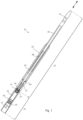
Figure 1 represents in a simplified section view, a possible embodiment of the present invention applied to an intramedullary distractor for lengthening of long bones. -
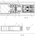
Figure 2a shows a detail of a magnetic transmission included in an embodiment of the present invention. -
Figure 2b shows again the magnetic transmission of an embodiment of the invention, one of the magnetic rotors having been moved away for clarity. -
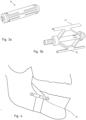
Figure 3a and 3b illustrate a not claimed embodiment that is a spine distractor -
Figure 4 shows a mandibular distractor. - The present invention is an intramedullary nail distractor for the correction of length deficit in long bones, like for example the femur, tibia, humerus, or any other long bone. As it is know in the art cited above, a possible therapy for such conditions comprises the surgically insertion in the medullary cavity of the target bone of a distracting nail comprising an actuator that allows to modify its overall length, and that can exert a sufficient linear force so as to promote bone growth on both sides of an artificial fracture line. Typically the implant is operated during a n extended time period according to a specified elongation plan and is usually left in place, as a passive structural intramedullary nail, once the bone has reached the desired length. The relative linear speed of the
connecting ends - According to one embodiment, as illustrated by
figures 1 and2a, 2b , the implantable device comprises adriving unit 25 and akinematic assembly 27 coaxially joined together: thedriving unit 25 is placed at one extremity of the intramedullary nail, and includes anelectric motor 35 that can be set into rotation by a command unit, not visible in the figure, and a source ofelectrical energy 32, for example a stack of lithium cells or another suitable primary or secondary (rechargeable) electrical battery. - The
driving unit 25 is fully enclosed into ahermetic capsule 20, for example made of titanium, PEEK, or of any suitable biocompatible material. The purpose of the capsule is to prevent the ingress of body fluids into the space that encloses the electronics, the electric motor, and the battery, and effectively prevent any contact between these component and body tissue. Preferably the capsule is hermetically sealed or welded and does not present any opening so as to guarantee containment for an essentially indefinite time. More preferably, the whole driving unit is contained in a double sealed capsule so as to prevent any contamination. - In a possible variant of the invention, the battery pack may be contained in a separate hermetic capsule distinct from that that encloses the
motor 35, and the capsule have pass-through electric connectors to allow the transmission of electric energy from one to the other. - In some occasions, it may be advantageous to provide a separate energy source, to which the implantable device is connectable. The energy source could be positioned inside or outside the body and transmit the energy to the implantable device by means of an appropriate wired or wireless connection. This variant of the invention is particularly suitable, for example, when the actuator must be operated during a long time span, or when a suitable autonomous battery could not fit in the space available at implantation site. According to the needs, the implantable device may be entirely dependent from the external energy supply for its functioning, or include a rechargeable accumulator that can be replenished by the external energy source.
- Wireless energy transmission could be obtained by electric or magnetic induction, or by an ultrasonic converter, or by any other suitable energy transmission means.
- The
electric motor 35 is connected, directly or indirectly, to a firstmagnetic rotor 37, also comprised in thecapsule 20 that presents an arrangement of alternate magnetic poles. Its rotation is transmitted, by magnetic coupling, to a secondmagnetic rotor 41 outside thecapsule 20, magnetically coupled to said first magnetic rotor such that it can be rotationally driven by the motor.Figures 2a and 2b represent a possible arrangement of such coupledrotors - In most orthopaedic applications displacement speeds are very low, and the forces exerted are fairly high, thus requiring a reduction system. In the presented example, as shown by
figures 2 and3a , the reduction is obtained by agearbox 45, for example a cascade of planetary reductions, and by the final lead-screw 48 andnut 49 transmission that transforms the rotary motion at the output of thegear reduction 45 into a linear motion of theplunger 60 relative to thesleeve 50. The reduction system of this embodiment, comprising theplanetary stages 45, and the lead-screw and nut assembly is not enclosed into a hermetic capsule and, therefore, it can enter in contact with body fluids, and is in fact lubricated by body fluids. Accordingly, it is integrally built with biocompatible materials like titanium, Cobalt-Chrome alloy, nitinol, stainless steel, Polyethylene, PEEK, PET, PTFE, biocompatible ceramic, or any other suitable biocompatible material. - In a typical application, the reduction ratio of the
gearbox 45 is comprised between 500:1 and 2000:1. For example, a cascade of five 4:1 planetary stages could be used to achieve an overall reduction ratio of 1024:1. In such manner, assuming a rotation speed of the about 1000 rpm for themotor 35, the lead-screw 40 could turn at about one revolution per minute. - In other non represented variants, the reduction system could use harmonic reducers, wobbling gears, cycloidal gears, or other transmission systems achieving the desired transmission ratios.
- In clinical limb-lengthening practice, the distraction plan spans over a periods of several days or weeks, during which the patient is encouraged to move and exercise the treated limb. Accordingly, the
gearbox 45 and the lead-screw/nut assembly axial bearings 46 in thegearbox 45. In a preferred embodiment the bearings have titanium cages and ceramic balls or rollers. -
Figure 2a shows, perhaps more clearly, the disposition of themagnetic rotors second rotor 41, which is not protected inside thehermetic capsule 20, has preferably the magnetic materials covered by a protective biocompatible material (not visible). Advantageously, themotor 35 in thehermetic capsule 20, themagnetic rotors reduction system 45, the lead-screw 48, and thenut 49 are all coaxially aligned and each element is directly connected to the following one, thus, the transmission is efficient and compact. - As mentioned above, the actuator is wholly contained in the implantable nail, and does not rely on external sources of energy or pressurised fluids for its operation. Another advantageous feature is that the whole transmission chain is reversible, in the sense that the linear relative motion of the
attachment points - Preferably, the driving unit also comprises a remotely-controllable command circuit that determines the rotation or the stop of the
motor 35. Thanks to this feature, the motor can be operated after the implantation, based on a predetermined post-operatory plan and/or on clinical and X-ray observations. Several remote control systems can be accommodated in the frame of the invention. In a possible variant, the command circuit includes magnetic field sensors, for example hall sensors. In this manner, a surgeon can control the operation of themotor 35 by placing permanent magnet at predetermined positions outside the implanted limb, preferably in this case, the command circuit has two magnetic field sensors at spaced-apart positions, one for operating the actuator in the normal, lengthening direction, and another for reversing the distraction. - In the example shown, the lead-screw transmission is preferably self-locking, in the sense that the nail normally resists to axial loads without changing its length unless the electric motor is active. If needed, an active locking mechanism can be added to the implant.
- The invention admits also other forms of remote control, for example by radio transmission, near-field electromagnetic communication, ultrasounds, or any other suitable wireless communication system.
- The variants of
figures 1 ,2 ,3a, 3b are specially adapted for an implantation in the medullary canal of long bones.Figures 3a, 3b illustrate a not claimed variant of the invention applicable to other parts of the skeleton, in particular in the treatment of the spine and of scoliosis. In this variant the lead-screw 48 operates an articulatedjack 13 that can be used as implantable spine distractor.Figure 4 , on the other hand, illustrates the possible implantation of adevice 15 used as a Cranio-Maxillo distractor. In this application, the implant is fixed outside of a bone, in this case a mandible. - Other applications are possible, including limb length correction, both congenital and posttraumatic; poliomyelitis; pseudoarthrosis; bone stump extension after amputations; bone transport after tumour resection; unilateral or bilateral impaired or abnormal growth; tumour prosthetic knee; cosmetic lengthening; Orthognatic surgery; correction of jaw deformities; Craniomaxillofacial distraction; Alveolar Ridge distraction; Multi-vector distraction; and, in the spine district, non-fusion scoliosis and other orthopaedic conditions.
-
- 10
- intramedullary distractor
- 13
- spine distractor
- 15
- Cranio-Maxillo distractor
- 20
- hermetic capsule
- 25
- driving unit
- 27
- kinematic assembly
- 31
- attachment region
- 32
- battery pack
- 35
- motor
- 37
- magnetic rotor
- 40
- lead-screw
- 41
- magnetic rotor
- 44
- radial bearing
- 45
- planetary reductions
- 46
- axial bearing
- 49
- nut
- 50
- sleeve
- 60
- plunger
- 61
- attachment region
- 71
- flat pusher
- 72
- flat pusher
Claims (12)
- Implantable intramedullary distractor for lengthening of long bones device comprising a driving unit (25) and a kinematic assembly (27) joined together: the driving unit (25) comprising an electric motor (35) driving a first magnetic rotor (37); the kinematic assembly (27) comprising a second magnetic rotor (41), magnetically coupled to said first magnetic rotor (37) such that it can be rotationally driven by the motor (35), and an actuator driven by the second rotor (41), whereinthe driving unit (25) is enclosed into an hermetic capsule (20) ; andthe second magnetic rotor (41) is outside the hermetic capsule (20); andthe implantable device has a first and a second connection regions (31,61) for attaching to bone, the actuator being arranged as to generate a relative motion of said first and second connection regions (31,61)..
- The implantable intramedullary distractor of the preceding claim, wherein said actuator consists in a leadscrew-nut distractor, a jack distractor.
- The implantable intramedullary distractor of any of the preceding claims, wherein said second magnetic rotor (41) drives said actuator through a reduction unit (45).
- The implantable intramedullary distractor of any of the preceding claims, wherein said actuator and/or said reduction unit (45) are lubricated by body fluids
- The implantable intramedullary distractor of any of the preceding claims, further comprising an autonomous source (32) of electrical energy in the hermetic capsule (20).
- The implantable intramedullary distractor of any of the preceding claims, connectable to an external source of energy.
- The implantable intramedullary distractor of any of claims from 4 to 7, in which said reduction unit (45) comprises one or more bearing systems (46) capable of transmitting axial loads
- The implantable intramedullary distractor of the previous claim, in which said bearings (46) include ceramic balls or rollers and titanium cages.
- The implantable intramedullary distractor of any of the previous claims, in which said hermetic capsule (20) consists in a hermetic titanium tube.
- The implantable intramedullary distractor of any of claims 4-10, wherein said reduction unit (45) comprises a planetary gear system, a spline reduction unit, or a wobble reduction unit.
- The implantable intramedullary distractor of any of the previous claims, including a wireless control unit arranged for starting and/or stopping and/or reversing the motion of the electric motor.
- The implantable intramedullary distractor of the previous claim, wherein said wireless control unit comprises magnetic field sensor responsive to the position of permanent magnets out of the patient's body.
Priority Applications (7)
| Application Number | Priority Date | Filing Date | Title |
|---|---|---|---|
| EP14158156.1A EP2915496B2 (en) | 2014-03-06 | 2014-03-06 | Implantable device |
| ES14158156T ES2617556T5 (en) | 2014-03-06 | 2014-03-06 | Implantable device |
| US15/123,206 US10251676B2 (en) | 2014-03-06 | 2015-03-06 | Implantable device |
| CN201580011972.3A CN106456216B (en) | 2014-03-06 | 2015-03-06 | Implantable device |
| PCT/EP2015/054719 WO2015132382A1 (en) | 2014-03-06 | 2015-03-06 | Implantable device |
| EP15709457.4A EP3113703B1 (en) | 2014-03-06 | 2015-03-06 | Implantable device |
| ES15709457T ES2745805T3 (en) | 2014-03-06 | 2015-03-06 | Implantable device |
Applications Claiming Priority (1)
| Application Number | Priority Date | Filing Date | Title |
|---|---|---|---|
| EP14158156.1A EP2915496B2 (en) | 2014-03-06 | 2014-03-06 | Implantable device |
Publications (3)
| Publication Number | Publication Date |
|---|---|
| EP2915496A1 EP2915496A1 (en) | 2015-09-09 |
| EP2915496B1 EP2915496B1 (en) | 2016-11-30 |
| EP2915496B2 true EP2915496B2 (en) | 2024-06-26 |
Family
ID=50238209
Family Applications (2)
| Application Number | Title | Priority Date | Filing Date |
|---|---|---|---|
| EP14158156.1A Active EP2915496B2 (en) | 2014-03-06 | 2014-03-06 | Implantable device |
| EP15709457.4A Active EP3113703B1 (en) | 2014-03-06 | 2015-03-06 | Implantable device |
Family Applications After (1)
| Application Number | Title | Priority Date | Filing Date |
|---|---|---|---|
| EP15709457.4A Active EP3113703B1 (en) | 2014-03-06 | 2015-03-06 | Implantable device |
Country Status (5)
| Country | Link |
|---|---|
| US (1) | US10251676B2 (en) |
| EP (2) | EP2915496B2 (en) |
| CN (1) | CN106456216B (en) |
| ES (2) | ES2617556T5 (en) |
| WO (1) | WO2015132382A1 (en) |
Families Citing this family (39)
| Publication number | Priority date | Publication date | Assignee | Title |
|---|---|---|---|---|
| EP2367486B1 (en) * | 2008-10-31 | 2024-07-10 | Implantica Patent Ltd. | Device for bone adjustment with anchoring function |
| US9179938B2 (en) * | 2013-03-08 | 2015-11-10 | Ellipse Technologies, Inc. | Distraction devices and method of assembling the same |
| US10238427B2 (en) * | 2015-02-19 | 2019-03-26 | Nuvasive Specialized Orthopedics, Inc. | Systems and methods for vertebral adjustment |
| WO2017066774A1 (en) * | 2015-10-16 | 2017-04-20 | Nuvasive Specialized Orthopedics, Inc. | Adjustable devices for treating arthritis of the knee |
| US10307190B2 (en) * | 2016-04-15 | 2019-06-04 | Arthrex, Inc. | Arthrodesis devices for generating and applying compression within joints |
| CA3082360C (en) * | 2016-11-09 | 2023-08-01 | Children's Hospital Medical Center Of Akron | Distraction osteogenesis system |
| ES2670449B1 (en) * | 2016-11-29 | 2019-03-07 | Fundacion Para La Investigacion Biomedica Del Hospital Univ De La Princesa | MANDIBULAR DISTRACTOR |
| US10646213B2 (en) * | 2016-12-19 | 2020-05-12 | Warsaw Orthopedic, Inc. | Remote spinal manipulating assembly and method for remote spinal manipulation |
| PL3491998T3 (en) | 2017-11-30 | 2021-11-15 | Endotact | Implantable distraction device |
| US10912652B2 (en) | 2018-07-09 | 2021-02-09 | Arthrex, Inc. | Arthroplasty implant systems for generating and applying dynamic compression |
| CN108703798A (en) * | 2018-08-13 | 2018-10-26 | 北京大学人民医院 | The noninvasive growing rod of contactless electromagnetic drive for scoliosis orthopedic |
| US12357792B2 (en) | 2019-01-04 | 2025-07-15 | Shifamed Holdings, Llc | Internal recharging systems and methods of use |
| TR201907277A2 (en) * | 2019-05-14 | 2020-11-23 | Univ Yildiz Teknik | Tumor prosthesis autonomous control and extension system. |
| DE102019122354A1 (en) * | 2019-08-20 | 2021-02-25 | Orthofix Srl | Intramedullary nail for distraction of a long bone |
| KR102090905B1 (en) * | 2019-10-04 | 2020-03-19 | 삼익티에이치케이 주식회사 | Fracture and bone deformation restoration device with heat emission function of drive module |
| KR102090904B1 (en) * | 2019-10-04 | 2020-03-19 | 삼익티에이치케이 주식회사 | Fracture and bone deformation restoration device with safety function |
| TW202120031A (en) * | 2019-11-15 | 2021-06-01 | 柏力科技股份有限公司 | Expandable vertebral device with triangular connection beam |
| WO2021217059A1 (en) | 2020-04-23 | 2021-10-28 | Shifamed Holdings, Llc | Power management for interatrial shunts and associated systems and methods |
| CN111603233A (en) * | 2020-06-15 | 2020-09-01 | 四川大学华西医院 | A kind of bone lengthening intramedullary nail device |
| US12605192B2 (en) | 2020-07-15 | 2026-04-21 | Globus Medical, Inc. | Ultrasonic communication in adjustable implants |
| CN112263316B (en) * | 2020-10-22 | 2021-08-17 | 中国科学院力学研究所 | An extensible intramedullary needle with mechanical self-locking function |
| CN112780754B (en) * | 2021-01-20 | 2023-03-21 | 清华大学 | Rod-shaped device |
| CN112780753A (en) * | 2021-01-20 | 2021-05-11 | 清华大学 | Rod-shaped device |
| US11806054B2 (en) * | 2021-02-23 | 2023-11-07 | Nuvasive Specialized Orthopedics, Inc. | Adjustable implant, system and methods |
| US12396767B2 (en) | 2021-03-24 | 2025-08-26 | Smith & Nephew, Inc | Implantable motorized bone adjustment devices |
| US11737787B1 (en) * | 2021-05-27 | 2023-08-29 | Nuvasive, Inc. | Bone elongating devices and methods of use |
| AU2022325024A1 (en) | 2021-08-03 | 2024-02-22 | Nuvasive Specialized Orthopedics, Inc. | Adjustable implant |
| US11612421B1 (en) * | 2021-09-20 | 2023-03-28 | Little Engine, LLC | Tensioner-balancer for knee joint |
| EP4444202B1 (en) * | 2021-12-07 | 2025-11-26 | NuVasive Specialized Orthopedics, Inc. | Adjustable implant with cycloid gears |
| US12121270B2 (en) * | 2022-02-25 | 2024-10-22 | Globus Medical, Inc. | Implantable osteodistraction device |
| PL441270A1 (en) * | 2022-05-25 | 2023-11-27 | Yuton Spółka Z Ograniczoną Odpowiedzialnością | Dynamic intramedullary nail with hybrid drive |
| US11642118B1 (en) | 2022-06-07 | 2023-05-09 | Little Engine, LLC | Knee tensioner-balancer and method |
| US11612503B1 (en) | 2022-06-07 | 2023-03-28 | Little Engine, LLC | Joint soft tissue evaluation method |
| US11839550B1 (en) | 2022-06-07 | 2023-12-12 | Little Engine, LLC | Machine learning based joint evaluation method |
| US12458417B2 (en) * | 2022-08-15 | 2025-11-04 | Nuvasive Specialized Orthopedics Inc. | Intermedullary lengthening implant with integrated load sensor |
| EP4586938A1 (en) * | 2022-09-13 | 2025-07-23 | NuVasive Specialized Orthopedics, Inc. | Torque transfer mechanisms |
| US12232790B2 (en) | 2022-12-30 | 2025-02-25 | IvyTech Design LLC | Adjustable angle orthopedic distractor, compressor, and distractor-compressor |
| US12491032B2 (en) | 2023-11-01 | 2025-12-09 | Dynamic Balancer Systems Llc | Knee arthroplasty method |
| US12303405B2 (en) | 2023-11-01 | 2025-05-20 | Dynamic Balancer Systems Llc | Knee arthroplasty method |
Citations (9)
| Publication number | Priority date | Publication date | Assignee | Title |
|---|---|---|---|---|
| WO1997037698A1 (en) † | 1996-04-04 | 1997-10-16 | Rau Guenter | Intravascular blood pump |
| DE19700225A1 (en) † | 1997-01-07 | 1998-07-09 | Augustin Prof Dr Betz | Distraction device for moving two parts of a bone apart |
| DE10055519A1 (en) † | 2000-11-09 | 2002-06-06 | Wittenstein Gmbh & Co Kg | distraction |
| DE10340025A1 (en) † | 2003-08-28 | 2005-03-24 | Wittenstein Ag | Surgical device for bone extension, comprising planetary gear acting on outer sleeve serving as ring gear |
| WO2006111173A1 (en) † | 2005-04-16 | 2006-10-26 | Aesculap Ag & Co. Kg | Surgical machine and method for controlling and/or regulating the same |
| DE102006036948A1 (en) † | 2006-08-06 | 2008-02-07 | Akdis, Mustafa, Dipl.-Ing. | blood pump |
| CN102144943A (en) † | 2011-04-27 | 2011-08-10 | 清华大学 | Non-invasive telescopic false body |
| DE102010047738A1 (en) † | 2010-08-26 | 2012-03-01 | Wittenstein Ag | Actuator for scoliosis correction |
| DE102011009867A1 (en) † | 2011-01-31 | 2012-08-02 | Heraeus Precious Metals Gmbh & Co. Kg | Ceramic bushing for a medically implantable device |
Family Cites Families (25)
| Publication number | Priority date | Publication date | Assignee | Title |
|---|---|---|---|---|
| CH581988A5 (en) * | 1974-04-09 | 1976-11-30 | Messerschmitt Boelkow Blohm | |
| DE3921972C2 (en) * | 1989-07-04 | 1994-06-09 | Rainer Dr Med Baumgart | Intramedullary nail |
| US5334184A (en) * | 1992-06-30 | 1994-08-02 | Bimman Lev A | Apparatus for intramedullary fixation broken bones |
| US5626581A (en) | 1995-11-27 | 1997-05-06 | Volunteers For Medical Engineering | Implantable bone lengthening apparatus |
| DE19906423A1 (en) | 1999-02-16 | 2000-08-17 | Wittenstein Gmbh & Co Kg | Active marrow spike for drawing out sections of bone consists of two elements moving against each other and electrically operated driving element to supply spike with electrical energy via detachable plug-in element. |
| DE10317776A1 (en) | 2003-04-16 | 2004-11-04 | Wittenstein Ag | Device for lengthening bones or parts of bones |
| US7623904B2 (en) * | 2003-08-06 | 2009-11-24 | Olympus Corporation | Medical apparatus, medical apparatus guide system, capsule type medical apparatus, and capsule type medical apparatus guide apparatus |
| FR2869218B1 (en) | 2004-04-21 | 2006-06-09 | Europlak Sa | GASTRIC CERCLING DEVICE OR MOTORIZED "GASTRIC RING" HAVING AT LEAST ONE RECEIVED ANTENNA FOR DELIVERY, REMOTE CONTROL AND DATA SENDING BY INDUCTION |
| US7955357B2 (en) * | 2004-07-02 | 2011-06-07 | Ellipse Technologies, Inc. | Expandable rod system to treat scoliosis and method of using the same |
| US7763053B2 (en) * | 2004-08-30 | 2010-07-27 | Gordon Jeffrey D | Implant for correction of spinal deformity |
| US8439915B2 (en) * | 2004-09-29 | 2013-05-14 | The Regents Of The University Of California | Apparatus and methods for magnetic alteration of anatomical features |
| FR2906453B1 (en) * | 2006-10-03 | 2009-03-06 | Arnaud Andre Soubeiran | INTRA-BODY LIFTING DEVICE WITH PERMANENT MAGNET. |
| US7753915B1 (en) | 2007-06-14 | 2010-07-13 | August Eksler | Bi-directional bone length adjustment system |
| US20090076597A1 (en) * | 2007-09-19 | 2009-03-19 | Jonathan Micheal Dahlgren | System for mechanical adjustment of medical implants |
| US20090093890A1 (en) * | 2007-10-04 | 2009-04-09 | Daniel Gelbart | Precise control of orthopedic actuators |
| US20090112263A1 (en) * | 2007-10-30 | 2009-04-30 | Scott Pool | Skeletal manipulation system |
| KR101045933B1 (en) * | 2008-05-02 | 2011-07-01 | 김가브리엘민 | Calibration device |
| DE102008036689A1 (en) | 2008-08-06 | 2010-02-11 | Feld, Christoph M. | distraction |
| WO2010061391A1 (en) * | 2008-11-28 | 2010-06-03 | Rad Dental Devices Ltd. | Bidirectional alveolar ridge distractor |
| FR2961386B1 (en) | 2010-06-21 | 2012-07-27 | Arnaud Soubeiran | INTRA-MEDALLIC DEVICE FOR THE RELATIVE MOVEMENT OF TWO LOCKED BONE PORTIONS BY THE MEDULLARY CHANNEL. |
| US8901775B2 (en) | 2010-12-10 | 2014-12-02 | Everheart Systems, Inc. | Implantable wireless power system |
| US8961567B2 (en) * | 2010-11-22 | 2015-02-24 | DePuy Synthes Products, LLC | Non-fusion scoliosis expandable spinal rod |
| US9153900B2 (en) * | 2011-10-14 | 2015-10-06 | Biomet Manufacturing Corp. | Implantable subcutaneous electrical socket and percutaneous plug |
| US9343923B2 (en) | 2012-08-23 | 2016-05-17 | Cyberonics, Inc. | Implantable medical device with backscatter signal based communication |
| CN103494636B (en) * | 2013-09-23 | 2016-08-10 | 李登宇 | A kind of can fix and orthotic device the spinal column of automatic telescopic in vivo |
-
2014
- 2014-03-06 EP EP14158156.1A patent/EP2915496B2/en active Active
- 2014-03-06 ES ES14158156T patent/ES2617556T5/en active Active
-
2015
- 2015-03-06 WO PCT/EP2015/054719 patent/WO2015132382A1/en not_active Ceased
- 2015-03-06 EP EP15709457.4A patent/EP3113703B1/en active Active
- 2015-03-06 ES ES15709457T patent/ES2745805T3/en active Active
- 2015-03-06 US US15/123,206 patent/US10251676B2/en active Active
- 2015-03-06 CN CN201580011972.3A patent/CN106456216B/en active Active
Patent Citations (9)
| Publication number | Priority date | Publication date | Assignee | Title |
|---|---|---|---|---|
| WO1997037698A1 (en) † | 1996-04-04 | 1997-10-16 | Rau Guenter | Intravascular blood pump |
| DE19700225A1 (en) † | 1997-01-07 | 1998-07-09 | Augustin Prof Dr Betz | Distraction device for moving two parts of a bone apart |
| DE10055519A1 (en) † | 2000-11-09 | 2002-06-06 | Wittenstein Gmbh & Co Kg | distraction |
| DE10340025A1 (en) † | 2003-08-28 | 2005-03-24 | Wittenstein Ag | Surgical device for bone extension, comprising planetary gear acting on outer sleeve serving as ring gear |
| WO2006111173A1 (en) † | 2005-04-16 | 2006-10-26 | Aesculap Ag & Co. Kg | Surgical machine and method for controlling and/or regulating the same |
| DE102006036948A1 (en) † | 2006-08-06 | 2008-02-07 | Akdis, Mustafa, Dipl.-Ing. | blood pump |
| DE102010047738A1 (en) † | 2010-08-26 | 2012-03-01 | Wittenstein Ag | Actuator for scoliosis correction |
| DE102011009867A1 (en) † | 2011-01-31 | 2012-08-02 | Heraeus Precious Metals Gmbh & Co. Kg | Ceramic bushing for a medically implantable device |
| CN102144943A (en) † | 2011-04-27 | 2011-08-10 | 清华大学 | Non-invasive telescopic false body |
Also Published As
| Publication number | Publication date |
|---|---|
| CN106456216B (en) | 2020-09-18 |
| US20170172624A1 (en) | 2017-06-22 |
| WO2015132382A1 (en) | 2015-09-11 |
| EP3113703A1 (en) | 2017-01-11 |
| ES2745805T3 (en) | 2020-03-03 |
| EP3113703B1 (en) | 2019-06-26 |
| CN106456216A (en) | 2017-02-22 |
| EP2915496B1 (en) | 2016-11-30 |
| EP2915496A1 (en) | 2015-09-09 |
| ES2617556T3 (en) | 2017-06-19 |
| ES2617556T5 (en) | 2024-12-03 |
| US10251676B2 (en) | 2019-04-09 |
Similar Documents
| Publication | Publication Date | Title |
|---|---|---|
| EP2915496B1 (en) | Implantable device | |
| US12290290B2 (en) | System and method for altering rotational alignment of bone sections | |
| US11944358B2 (en) | Bone growth device and method | |
| AU2014331685B2 (en) | Methods and apparatus for bone reshaping | |
| BG65672B1 (en) | Corrective surgical device | |
| WO2010050891A1 (en) | Device and method for bone adjustment operating with wireless transmission energy |
Legal Events
| Date | Code | Title | Description |
|---|---|---|---|
| PUAI | Public reference made under article 153(3) epc to a published international application that has entered the european phase |
Free format text: ORIGINAL CODE: 0009012 |
|
| AK | Designated contracting states |
Kind code of ref document: A1 Designated state(s): AL AT BE BG CH CY CZ DE DK EE ES FI FR GB GR HR HU IE IS IT LI LT LU LV MC MK MT NL NO PL PT RO RS SE SI SK SM TR |
|
| AX | Request for extension of the european patent |
Extension state: BA ME |
|
| 17P | Request for examination filed |
Effective date: 20160208 |
|
| RBV | Designated contracting states (corrected) |
Designated state(s): AL AT BE BG CH CY CZ DE DK EE ES FI FR GB GR HR HU IE IS IT LI LT LU LV MC MK MT NL NO PL PT RO RS SE SI SK SM TR |
|
| GRAP | Despatch of communication of intention to grant a patent |
Free format text: ORIGINAL CODE: EPIDOSNIGR1 |
|
| INTG | Intention to grant announced |
Effective date: 20160630 |
|
| GRAS | Grant fee paid |
Free format text: ORIGINAL CODE: EPIDOSNIGR3 |
|
| GRAA | (expected) grant |
Free format text: ORIGINAL CODE: 0009210 |
|
| AK | Designated contracting states |
Kind code of ref document: B1 Designated state(s): AL AT BE BG CH CY CZ DE DK EE ES FI FR GB GR HR HU IE IS IT LI LT LU LV MC MK MT NL NO PL PT RO RS SE SI SK SM TR |
|
| REG | Reference to a national code |
Ref country code: CH Ref legal event code: EP Ref country code: GB Ref legal event code: FG4D |
|
| REG | Reference to a national code |
Ref country code: CH Ref legal event code: NV Representative=s name: P&TS SA, CH Ref country code: AT Ref legal event code: REF Ref document number: 849070 Country of ref document: AT Kind code of ref document: T Effective date: 20161215 |
|
| REG | Reference to a national code |
Ref country code: IE Ref legal event code: FG4D |
|
| REG | Reference to a national code |
Ref country code: DE Ref legal event code: R096 Ref document number: 602014005113 Country of ref document: DE |
|
| REG | Reference to a national code |
Ref country code: NL Ref legal event code: FP |
|
| PG25 | Lapsed in a contracting state [announced via postgrant information from national office to epo] |
Ref country code: LV Free format text: LAPSE BECAUSE OF FAILURE TO SUBMIT A TRANSLATION OF THE DESCRIPTION OR TO PAY THE FEE WITHIN THE PRESCRIBED TIME-LIMIT Effective date: 20161130 |
|
| REG | Reference to a national code |
Ref country code: FR Ref legal event code: PLFP Year of fee payment: 4 |
|
| REG | Reference to a national code |
Ref country code: LT Ref legal event code: MG4D |
|
| REG | Reference to a national code |
Ref country code: AT Ref legal event code: MK05 Ref document number: 849070 Country of ref document: AT Kind code of ref document: T Effective date: 20161130 |
|
| PG25 | Lapsed in a contracting state [announced via postgrant information from national office to epo] |
Ref country code: SE Free format text: LAPSE BECAUSE OF FAILURE TO SUBMIT A TRANSLATION OF THE DESCRIPTION OR TO PAY THE FEE WITHIN THE PRESCRIBED TIME-LIMIT Effective date: 20161130 Ref country code: NO Free format text: LAPSE BECAUSE OF FAILURE TO SUBMIT A TRANSLATION OF THE DESCRIPTION OR TO PAY THE FEE WITHIN THE PRESCRIBED TIME-LIMIT Effective date: 20170228 Ref country code: LT Free format text: LAPSE BECAUSE OF FAILURE TO SUBMIT A TRANSLATION OF THE DESCRIPTION OR TO PAY THE FEE WITHIN THE PRESCRIBED TIME-LIMIT Effective date: 20161130 Ref country code: GR Free format text: LAPSE BECAUSE OF FAILURE TO SUBMIT A TRANSLATION OF THE DESCRIPTION OR TO PAY THE FEE WITHIN THE PRESCRIBED TIME-LIMIT Effective date: 20170301 |
|
| PG25 | Lapsed in a contracting state [announced via postgrant information from national office to epo] |
Ref country code: HR Free format text: LAPSE BECAUSE OF FAILURE TO SUBMIT A TRANSLATION OF THE DESCRIPTION OR TO PAY THE FEE WITHIN THE PRESCRIBED TIME-LIMIT Effective date: 20161130 Ref country code: PL Free format text: LAPSE BECAUSE OF FAILURE TO SUBMIT A TRANSLATION OF THE DESCRIPTION OR TO PAY THE FEE WITHIN THE PRESCRIBED TIME-LIMIT Effective date: 20161130 Ref country code: PT Free format text: LAPSE BECAUSE OF FAILURE TO SUBMIT A TRANSLATION OF THE DESCRIPTION OR TO PAY THE FEE WITHIN THE PRESCRIBED TIME-LIMIT Effective date: 20170330 Ref country code: RS Free format text: LAPSE BECAUSE OF FAILURE TO SUBMIT A TRANSLATION OF THE DESCRIPTION OR TO PAY THE FEE WITHIN THE PRESCRIBED TIME-LIMIT Effective date: 20161130 Ref country code: AT Free format text: LAPSE BECAUSE OF FAILURE TO SUBMIT A TRANSLATION OF THE DESCRIPTION OR TO PAY THE FEE WITHIN THE PRESCRIBED TIME-LIMIT Effective date: 20161130 |
|
| REG | Reference to a national code |
Ref country code: ES Ref legal event code: FG2A Ref document number: 2617556 Country of ref document: ES Kind code of ref document: T3 Effective date: 20170619 |
|
| PG25 | Lapsed in a contracting state [announced via postgrant information from national office to epo] |
Ref country code: DK Free format text: LAPSE BECAUSE OF FAILURE TO SUBMIT A TRANSLATION OF THE DESCRIPTION OR TO PAY THE FEE WITHIN THE PRESCRIBED TIME-LIMIT Effective date: 20161130 Ref country code: SK Free format text: LAPSE BECAUSE OF FAILURE TO SUBMIT A TRANSLATION OF THE DESCRIPTION OR TO PAY THE FEE WITHIN THE PRESCRIBED TIME-LIMIT Effective date: 20161130 Ref country code: RO Free format text: LAPSE BECAUSE OF FAILURE TO SUBMIT A TRANSLATION OF THE DESCRIPTION OR TO PAY THE FEE WITHIN THE PRESCRIBED TIME-LIMIT Effective date: 20161130 Ref country code: CZ Free format text: LAPSE BECAUSE OF FAILURE TO SUBMIT A TRANSLATION OF THE DESCRIPTION OR TO PAY THE FEE WITHIN THE PRESCRIBED TIME-LIMIT Effective date: 20161130 Ref country code: EE Free format text: LAPSE BECAUSE OF FAILURE TO SUBMIT A TRANSLATION OF THE DESCRIPTION OR TO PAY THE FEE WITHIN THE PRESCRIBED TIME-LIMIT Effective date: 20161130 |
|
| REG | Reference to a national code |
Ref country code: DE Ref legal event code: R026 Ref document number: 602014005113 Country of ref document: DE |
|
| PG25 | Lapsed in a contracting state [announced via postgrant information from national office to epo] |
Ref country code: BG Free format text: LAPSE BECAUSE OF FAILURE TO SUBMIT A TRANSLATION OF THE DESCRIPTION OR TO PAY THE FEE WITHIN THE PRESCRIBED TIME-LIMIT Effective date: 20170228 Ref country code: SM Free format text: LAPSE BECAUSE OF FAILURE TO SUBMIT A TRANSLATION OF THE DESCRIPTION OR TO PAY THE FEE WITHIN THE PRESCRIBED TIME-LIMIT Effective date: 20161130 Ref country code: BE Free format text: LAPSE BECAUSE OF FAILURE TO SUBMIT A TRANSLATION OF THE DESCRIPTION OR TO PAY THE FEE WITHIN THE PRESCRIBED TIME-LIMIT Effective date: 20161130 |
|
| PLBI | Opposition filed |
Free format text: ORIGINAL CODE: 0009260 |
|
| 26 | Opposition filed |
Opponent name: LAKEVIEW INNOVATION LTD. Effective date: 20170830 |
|
| PLAX | Notice of opposition and request to file observation + time limit sent |
Free format text: ORIGINAL CODE: EPIDOSNOBS2 |
|
| PG25 | Lapsed in a contracting state [announced via postgrant information from national office to epo] |
Ref country code: SI Free format text: LAPSE BECAUSE OF FAILURE TO SUBMIT A TRANSLATION OF THE DESCRIPTION OR TO PAY THE FEE WITHIN THE PRESCRIBED TIME-LIMIT Effective date: 20161130 Ref country code: MC Free format text: LAPSE BECAUSE OF FAILURE TO SUBMIT A TRANSLATION OF THE DESCRIPTION OR TO PAY THE FEE WITHIN THE PRESCRIBED TIME-LIMIT Effective date: 20161130 |
|
| REG | Reference to a national code |
Ref country code: IE Ref legal event code: MM4A |
|
| PG25 | Lapsed in a contracting state [announced via postgrant information from national office to epo] |
Ref country code: LU Free format text: LAPSE BECAUSE OF NON-PAYMENT OF DUE FEES Effective date: 20170306 |
|
| PLBB | Reply of patent proprietor to notice(s) of opposition received |
Free format text: ORIGINAL CODE: EPIDOSNOBS3 |
|
| PG25 | Lapsed in a contracting state [announced via postgrant information from national office to epo] |
Ref country code: IE Free format text: LAPSE BECAUSE OF NON-PAYMENT OF DUE FEES Effective date: 20170306 |
|
| REG | Reference to a national code |
Ref country code: FR Ref legal event code: PLFP Year of fee payment: 5 |
|
| PG25 | Lapsed in a contracting state [announced via postgrant information from national office to epo] |
Ref country code: MT Free format text: LAPSE BECAUSE OF NON-PAYMENT OF DUE FEES Effective date: 20170306 |
|
| APBM | Appeal reference recorded |
Free format text: ORIGINAL CODE: EPIDOSNREFNO |
|
| APBP | Date of receipt of notice of appeal recorded |
Free format text: ORIGINAL CODE: EPIDOSNNOA2O |
|
| APAH | Appeal reference modified |
Free format text: ORIGINAL CODE: EPIDOSCREFNO |
|
| APBM | Appeal reference recorded |
Free format text: ORIGINAL CODE: EPIDOSNREFNO |
|
| APBP | Date of receipt of notice of appeal recorded |
Free format text: ORIGINAL CODE: EPIDOSNNOA2O |
|
| PG25 | Lapsed in a contracting state [announced via postgrant information from national office to epo] |
Ref country code: HU Free format text: LAPSE BECAUSE OF FAILURE TO SUBMIT A TRANSLATION OF THE DESCRIPTION OR TO PAY THE FEE WITHIN THE PRESCRIBED TIME-LIMIT; INVALID AB INITIO Effective date: 20140306 |
|
| APBQ | Date of receipt of statement of grounds of appeal recorded |
Free format text: ORIGINAL CODE: EPIDOSNNOA3O |
|
| APBQ | Date of receipt of statement of grounds of appeal recorded |
Free format text: ORIGINAL CODE: EPIDOSNNOA3O |
|
| PG25 | Lapsed in a contracting state [announced via postgrant information from national office to epo] |
Ref country code: CY Free format text: LAPSE BECAUSE OF FAILURE TO SUBMIT A TRANSLATION OF THE DESCRIPTION OR TO PAY THE FEE WITHIN THE PRESCRIBED TIME-LIMIT Effective date: 20161130 |
|
| PG25 | Lapsed in a contracting state [announced via postgrant information from national office to epo] |
Ref country code: MK Free format text: LAPSE BECAUSE OF FAILURE TO SUBMIT A TRANSLATION OF THE DESCRIPTION OR TO PAY THE FEE WITHIN THE PRESCRIBED TIME-LIMIT Effective date: 20161130 |
|
| REG | Reference to a national code |
Ref country code: DE Ref legal event code: R082 Ref document number: 602014005113 Country of ref document: DE Representative=s name: BECK & ROESSIG EUROPEAN PATENT ATTORNEYS, DE Ref country code: DE Ref legal event code: R082 Ref document number: 602014005113 Country of ref document: DE Representative=s name: BECK & ROESSIG - EUROPEAN PATENT ATTORNEYS, DE |
|
| PG25 | Lapsed in a contracting state [announced via postgrant information from national office to epo] |
Ref country code: TR Free format text: LAPSE BECAUSE OF FAILURE TO SUBMIT A TRANSLATION OF THE DESCRIPTION OR TO PAY THE FEE WITHIN THE PRESCRIBED TIME-LIMIT Effective date: 20161130 |
|
| PG25 | Lapsed in a contracting state [announced via postgrant information from national office to epo] |
Ref country code: AL Free format text: LAPSE BECAUSE OF FAILURE TO SUBMIT A TRANSLATION OF THE DESCRIPTION OR TO PAY THE FEE WITHIN THE PRESCRIBED TIME-LIMIT Effective date: 20161130 Ref country code: IS Free format text: LAPSE BECAUSE OF FAILURE TO SUBMIT A TRANSLATION OF THE DESCRIPTION OR TO PAY THE FEE WITHIN THE PRESCRIBED TIME-LIMIT Effective date: 20170330 |
|
| APBU | Appeal procedure closed |
Free format text: ORIGINAL CODE: EPIDOSNNOA9O |
|
| PGFP | Annual fee paid to national office [announced via postgrant information from national office to epo] |
Ref country code: NL Payment date: 20240320 Year of fee payment: 11 |
|
| PUAH | Patent maintained in amended form |
Free format text: ORIGINAL CODE: 0009272 |
|
| STAA | Information on the status of an ep patent application or granted ep patent |
Free format text: STATUS: PATENT MAINTAINED AS AMENDED |
|
| 27A | Patent maintained in amended form |
Effective date: 20240626 |
|
| AK | Designated contracting states |
Kind code of ref document: B2 Designated state(s): AL AT BE BG CH CY CZ DE DK EE ES FI FR GB GR HR HU IE IS IT LI LT LU LV MC MK MT NL NO PL PT RO RS SE SI SK SM TR |
|
| REG | Reference to a national code |
Ref country code: DE Ref legal event code: R102 Ref document number: 602014005113 Country of ref document: DE |
|
| PG25 | Lapsed in a contracting state [announced via postgrant information from national office to epo] |
Ref country code: NL Free format text: LAPSE BECAUSE OF FAILURE TO SUBMIT A TRANSLATION OF THE DESCRIPTION OR TO PAY THE FEE WITHIN THE PRESCRIBED TIME-LIMIT Effective date: 20161130 |
|
| PG25 | Lapsed in a contracting state [announced via postgrant information from national office to epo] |
Ref country code: NL Free format text: LAPSE BECAUSE OF FAILURE TO SUBMIT A TRANSLATION OF THE DESCRIPTION OR TO PAY THE FEE WITHIN THE PRESCRIBED TIME-LIMIT Effective date: 20161130 |
|
| REG | Reference to a national code |
Ref country code: ES Ref legal event code: DC2A Ref document number: 2617556 Country of ref document: ES Kind code of ref document: T5 Effective date: 20241203 |
|
| PGFP | Annual fee paid to national office [announced via postgrant information from national office to epo] |
Ref country code: FI Payment date: 20250324 Year of fee payment: 12 |
|
| PGFP | Annual fee paid to national office [announced via postgrant information from national office to epo] |
Ref country code: ES Payment date: 20250429 Year of fee payment: 12 |
|
| PGFP | Annual fee paid to national office [announced via postgrant information from national office to epo] |
Ref country code: CH Payment date: 20250401 Year of fee payment: 12 |
|
| REG | Reference to a national code |
Ref country code: CH Ref legal event code: U11 Free format text: ST27 STATUS EVENT CODE: U-0-0-U10-U11 (AS PROVIDED BY THE NATIONAL OFFICE) Effective date: 20260401 |
|
| PGFP | Annual fee paid to national office [announced via postgrant information from national office to epo] |
Ref country code: GB Payment date: 20260324 Year of fee payment: 13 |
|
| PGFP | Annual fee paid to national office [announced via postgrant information from national office to epo] |
Ref country code: DE Payment date: 20260319 Year of fee payment: 13 |
|
| PGFP | Annual fee paid to national office [announced via postgrant information from national office to epo] |
Ref country code: IT Payment date: 20260324 Year of fee payment: 13 |
|
| PGFP | Annual fee paid to national office [announced via postgrant information from national office to epo] |
Ref country code: FR Payment date: 20260320 Year of fee payment: 13 |