EP2914915B1 - Drying a refrigerated cargo box following wash out prior to loading - Google Patents
Drying a refrigerated cargo box following wash out prior to loading Download PDFInfo
- Publication number
- EP2914915B1 EP2914915B1 EP13762327.8A EP13762327A EP2914915B1 EP 2914915 B1 EP2914915 B1 EP 2914915B1 EP 13762327 A EP13762327 A EP 13762327A EP 2914915 B1 EP2914915 B1 EP 2914915B1
- Authority
- EP
- European Patent Office
- Prior art keywords
- heating
- cooling
- circulating air
- refrigeration unit
- cargo box
- Prior art date
- Legal status (The legal status is an assumption and is not a legal conclusion. Google has not performed a legal analysis and makes no representation as to the accuracy of the status listed.)
- Active
Links
Images

Classifications
-
- F—MECHANICAL ENGINEERING; LIGHTING; HEATING; WEAPONS; BLASTING
- F26—DRYING
- F26B—DRYING SOLID MATERIALS OR OBJECTS BY REMOVING LIQUID THEREFROM
- F26B21/00—Arrangements for supplying or controlling air or other gases for drying solid materials or objects
- F26B21/20—Circulating air or gases in closed cycles, e.g. wholly within the drying enclosure
-
- F—MECHANICAL ENGINEERING; LIGHTING; HEATING; WEAPONS; BLASTING
- F26—DRYING
- F26B—DRYING SOLID MATERIALS OR OBJECTS BY REMOVING LIQUID THEREFROM
- F26B25/00—Details of general application not covered by group F26B21/00 or F26B23/00
-
- F—MECHANICAL ENGINEERING; LIGHTING; HEATING; WEAPONS; BLASTING
- F26—DRYING
- F26B—DRYING SOLID MATERIALS OR OBJECTS BY REMOVING LIQUID THEREFROM
- F26B19/00—Machines or apparatus for drying solid materials or objects not covered by groups F26B9/00 - F26B17/00
- F26B19/005—Self-contained mobile devices, e.g. for agricultural produce
Definitions
- the method further includes if the sensed ambient temperature is not less than the freezing point of water, setting the setpoint control air temperature and operating the refrigeration unit in a cooling cycle for cooling the circulating air passing through the evaporator prior to operating the refrigeration unit in alternating cycles of first heating the circulating air and then cooling the circulating air.
- controller 40 is configured to monitor the temperature, T AM , of the ambient air 15 external of the trailer 12 through a temperature sensor 42, and the temperature of the supply air, T SA , having traversed the evaporator 30 and passing back to the cargo box 18 through the supply air duct 38, through a temperature sensor 44.
- the controller 40 initiates operation of the refrigerant vapor compression system in alternating cycles, first, at block 106 ("ENABLE HIGH SPEED HEAT MODE FOR 2 PRESET TIME PERIOD”), entering a heating cycle for heating the circulating box air to condition the box air for taking up moisture from the surfaces of the bounding walls of the cargo box 18 and then, at block 110 ("SET SETPOINT TO -2.2°C (28°F) AND ENABLE HIGH SPEED COOL MODE”), entering a cooling cycle for cooling the circulating box air and removing moisture therefrom as the circulating box air traverses the evaporator 30.
- the controller 40 monitors the supply air temperature, T SA , sensed by the supply air temperature sensor 44, and continuously determines whether the supply air temperature, T SA , has been cooled to a "LOW SPEED SWITCH POINT" corresponding to desired lower temperature below the freezing point of water, such as, for example, but not limited to -2.2°C (28°F). If not, the controller 40 continues operating the refrigerant vapor compression system in the cooling cycle ("HIGH SPEED COOLING MODE") (block 114). When the sensed supply air temperature has dropped to the desired lower temperature, the controller 40, at block 116, determines whether the drying period timer set at step 102 has expired. If the timer has not expired, the controller 40 returns to block 106 of the process flow chart and switches operation of the refrigerant vapor compression system into another heating cycle at block 106 to continue the alternate heating cycle/cooling cycle process.
- a "LOW SPEED SWITCH POINT" corresponding to desired lower temperature below the freezing point of water, such as, for example
Landscapes
- Engineering & Computer Science (AREA)
- Mechanical Engineering (AREA)
- General Engineering & Computer Science (AREA)
- Devices That Are Associated With Refrigeration Equipment (AREA)
Description
- This disclosure relates generally to the transport of perishable goods and, more particularly, to the preparation of a refrigerated cargo box for transport of a non-refrigerated product on a return leg of a transport haul after delivery of a refrigerated product.
- Refrigerated trucks, trailers and mobile containers are customarily equipped with a transport refrigeration unit operatively associated with the cargo box of the truck, trailer or mobile container for cooling the atmosphere within the cargo box. The transport refrigeration unit includes a refrigerant vapor compression system having a refrigerant evaporator heat exchanger. When transporting temperature sensitive perishable goods, ranging for example from fresh products, such as produce, meat and fish to frozen goods, such as deep frozen seafood, air from within the cargo box of the truck, trailer or container, is circulated through an evaporator heat exchanger in heat exchange relationship with refrigerant circulating through the refrigerant vapor compression system. Box air is drawn from the cargo box, referred to as return air, passed through the evaporator heat exchanger of a refrigeration vapor compression system of the transport refrigerant unit to cool the box air, and then circulated back to the cargo box. The air circulated back to the cargo box is referred to as supply air.
- After a refrigerated perishable product is delivered and unloaded from the cargo box of the truck, trailer or container, the truck, trailer or container may be hired to haul non-refrigerated perishable, dry product, such as for example, but not limited to, bags of flour or sugar or other dry goods for the return leg. In such case, it is customary to wash out the cargo box of the truck, trailer or container. The cargo box must then be allowed to dry out prior to loading the non-refrigerated perishable, dry product. Depending upon local ambient conditions, the natural drying of the cargo box may take several hours, resulting in delays in loading and departure, costly downtime, poor equipment utilization rates, scheduling issues, and general lack of productivity.
- An article dated May 30, 2012 published on http://www.thetruckersreport.com/truckingindustryforum/refrigerated-trucking-forum/179895-getting-reefer-dry-out-quickly-after.htm1
as retrieved on July 16, 2015 teaches that simultaneously heating and cooling air circulating through a cargo box may help to remove moisture from the cargo box. - A method is provided for accelerating the drying of a cargo box of a refrigerated truck, trailer, or container following a wash out. According to the invention, the method includes circulating air from the cargo box through an evaporator of the refrigerant unit and back to the cargo box; and operating the refrigerant unit in alternating cycles of first heating the circulating air and then cooling the circulating air.
- In an embodiment of the method, operating the refrigerant unit in alternating cycles of first heating the circulating air and then cooling the circulating air includes: heating the circulating air for a first period and upon expiration of the first period cooling the circulating air for a second period; and repeating the alternate heating and cooling cycles for a preset drying period of time. In each heating cycle, heating the circulating air for a first period may include heating the circulating air for a preset period of heating time. In each cooling cycle, cooling the circulating air for a second period may include cooling the circulating air until the circulating air passing back to the cargo box has been cooled to a preselected temperature.
- The method may further include at the completion of each cooling cycle determining whether the elapsed time from commencement of the drying process exceeds a preset drying period of time; and if the elapsed time from commencement of the drying process exceeds the preset drying period of time, terminating the drying process. The method may further include, upon termination of the drying process, operating the refrigeration unit in a defrost cycle for defrosting the evaporator.
- In an aspect, a method is provided for removing moisture from a cargo box of a mobile refrigerated container equipped with a refrigeration unit following a wash out of the cargo box by selectively operating the refrigerant unit in a remove moisture mode. The method includes: operating a fan operatively associated with an evaporator of the refrigeration unit for circulating air from the cargo box through the evaporator and back to the cargo box; determining whether a sensed ambient temperature is less than the freezing point of water; and if the sensed ambient temperature is less than the freezing point of water, operating the refrigeration unit in alternating cycles of first heating the circulating air and then cooling the circulating air. The method further includes if the sensed ambient temperature is not less than the freezing point of water, setting the setpoint control air temperature and operating the refrigeration unit in a cooling cycle for cooling the circulating air passing through the evaporator prior to operating the refrigeration unit in alternating cycles of first heating the circulating air and then cooling the circulating air.
- In an embodiment, operating the refrigeration unit in alternating cycles of first heating the circulating air and then cooling the circulating air includes: operating the refrigeration unit in a heating cycle and heating the circulating air passing through the evaporator for a preset heating period of time; upon termination of the heating cycle, setting a setpoint control air temperature and operating the refrigeration unit in a cooling cycle for cooling the circulating air passing through the evaporator; sensing a temperature of the circulating air having traversed the evaporator and being supplied back to the cargo box; comparing the sensed supply air temperature to the setpoint control air temperature; and terminating operation of the refrigeration unit in the cooling cycle when the sensed supply air temperature equals the setpoint control air temperature.
- The method may further include: determining an elapsed time from initiating operation of the refrigeration unit in the remove moisture mode; if the elapsed time is less than a preset drying period of time, repeating another heating cycle and cooling cycle sequence; and if the elapsed time equals or exceeds the preset drying period of time, terminating operation of the refrigeration unit in the remove moisture mode.
- For a further understanding of the disclosure, reference will be made to the following detailed description which is to be read in connection with the accompanying drawing, wherein:
-
FIG. 1 is a side elevation view of a refrigerated transport tractor-trailer equipped with a transport refrigeration unit for conditioning the atmosphere within the cargo box of the trailer; -
FIG. 2 is a side elevation view of an embodiment of the transport refrigeration unit mounted on the front wall of the trailer ofFIG. 1 ; and -
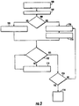
FIG. 3 is a process flow block diagram illustrating an embodiment of the method for removing moisture disclosed herein. - Referring initially to
FIG. 1 , there are depicted a refrigeratedtransport vehicle 12 adapted for transporting perishable goods in a temperature controlled environment. In the depicted embodiment, the refrigeratedtransport vehicle 12 is a refrigerated tractor-trailer having atractor 14 pulling atrailer 16 defining acargo box 18 wherein goods are stowed for transport. A transport refrigeration unit (commonly referred to as a TRU) 20 is mounted to thetrailer 16, for example to the front wall of thetrailer 16, for establishing and maintaining a temperature-controlled environment within thecargo box 18 after the goods are loaded into thecargo box 18 and thedoors 22, typically in the rear wall of thetrailer 16 are closed to seal thecargo box 18. - Referring now to
FIG. 2 , the TRU 20 includes a refrigerant vapor compression system having acompression device 24, a refrigerant heatrejection heat exchanger 26 and at least onefan 28 associated therewith, and a refrigerant heatabsorption heat exchanger 30 and at least onefan 32 associated therewith. The refrigerant heatrejection heat exchanger 26, which functions as refrigerant condenser if the refrigerant vapor compression system is operating in a subcritical refrigeration cycle and as a refrigeration gas cooler if the refrigerant vapor compression system is operating in a transcritical refrigeration cycle, will be referred to herein as condenser/gas cooler 26. Thecompression device 24, the condenser/gas cooler 26 and associated fan(s) 28 are located in a forward section of the TRU 20 located external from and thermally isolated from thecargo box 18. Thecompression device 24 typically comprises a reciprocating compressor or a scroll compressor, but other types of compressors may be used. - In a tractor-trailer application, the TRU 20 further includes a prime mover (not shown), typically in the form of a Diesel engine, that either drives the
compression device 24 directly through a mechanical coupling or a belt or chain drive, or drives a generator (not shown) that provides electric power for driving an electric motor for driving thecompression device 24. In truck applications, thecompression device 24 may be driven by electric power provided from a generator driven by the truck engine. In intermodal refrigerated container applications, the compression device may be driven by an electric motor powered by an onboard ship electric power supply or by electric power generated by a genset coupled to the TRU when the intermodal container is not onboard ship. - The refrigerant heat
absorption heat exchanger 30, which functions as an evaporator whether the refrigerant vapor compression system is operating in a subcritical or a transcritical cycle, will be referred to herein asevaporator 30. Theevaporator 30 and the evaporator fan(s) 32 are housed in an aft section of the TRU 20 in air flow communication with the interior of thecargo box 18 through areturn air duct 36 and asupply air duct 38, as illustrated inFIG. 2 . When the evaporator fan(s) 32 are operating, air is drawn from thecargo box 18 through thereturn duct 36, traversing theevaporator 30, and circulated back to thecargo box 18 through thesupply air duct 38. - The
compression device 24, the condenser/gas cooler 26, an expansion device (not shown), typically a thermostatic expansion valve or an electronic expansion valve, operatively associated with theevaporator 30, and theevaporator 30 are disposed in series refrigerant flow relationship in a closed loop refrigerant flow circuit and arranged to carry out a conventional refrigeration cycle. Anelectric heating element 34 may be disposed on the return air side, that is the upstream side with respect to air flow, of theevaporator 30. Thus, the refrigerant vapor compression system may be selectively operated in a cooling mode to cool the atmosphere within the closed environment within thecargo box 18 or in a heating mode to heat the atmosphere within the closed environment within thecargo box 18 so as to maintain the temperature within thecargo box 18 within a narrow range about a desired box temperature for the particular perishable product, fresh or frozen, being transport. - The TRU 20 also includes a
controller 40 in association with the refrigerant vapor compression system for controlling operation of the refrigerant vapor compression system in both the cooling mode and the heating mode. In an embodiment, thecontroller 40 may a microprocessor based controller. Thecontroller 40 is configured to control operation of thecompression device 24, as well as operation of the fan(s) 28 associated with the condenser/gas, the fan(s) 32 associated with theevaporator 30, theelectric heating element 34, and various valves and other components through the refrigerant vapor compression system. Thecontroller 40 is also configured to monitor various operating parameters, such as refrigerant pressures and/or refrigerant temperatures at various locations within the refrigerant flow circuit. Additionally, thecontroller 40 is configured to monitor the temperature, TAM, of theambient air 15 external of thetrailer 12 through atemperature sensor 42, and the temperature of the supply air, TSA, having traversed theevaporator 30 and passing back to thecargo box 18 through thesupply air duct 38, through atemperature sensor 44. - Referring now to
FIG. 3 , there is presented a process flow block diagram illustrating an embodiment of the method for removing moisture from the atmosphere within a cargo box of a refrigerated transport vehicle for accelerating the drying of the cargo box following a wash out of the cargo box. To initiate drying of thecargo box 18 after a wash out, the operator, atblock 100, selects a "Remove Moisture" option from a menu on a display associated with thecontroller 40. Of course, prior to initiating the drying process, the operator ensures that thedoors 22 to thecargo box 18 are closed to seal thecargo box 18. - Having been instructed to enter a remove moisture mode, the
controller 40, atblock 102, sets a timer for a desired elapsed period of drying time and starts the timer. The period of drying time may be selected by the operator or may be preprogrammed into thecontroller 40. For example, a period of drying time of one hour should be sufficient in most applications, although shorter or longer periods of drying time may be specified as desired. Atblock 104, thecontroller 40 determines whether the current ambient air temperature, T AM, external to thecargo box 18, as sensed by the ambientair temperature sensor 42, is less than the freezing point of water (32°F, 0°C). If the current ambient air temperature, T AM, is indeed less than 0°C (32°F), thecontroller 40 proceeds to block 106. However, if the current ambient air temperature is equal to or greater than, i.e. not less than, 0°C (32°F), thecontroller 40 proceeds to block 108. - If the current ambient air temperature, T AM, is indeed less than 0°C (32°F), the
controller 40 initiates operation of the refrigerant vapor compression system in alternating cycles, first, at block 106 ("ENABLE HIGH SPEED HEAT MODE FOR 2 PRESET TIME PERIOD"), entering a heating cycle for heating the circulating box air to condition the box air for taking up moisture from the surfaces of the bounding walls of thecargo box 18 and then, at block 110 ("SET SETPOINT TO -2.2°C (28°F) AND ENABLE HIGH SPEED COOL MODE"), entering a cooling cycle for cooling the circulating box air and removing moisture therefrom as the circulating box air traverses theevaporator 30. In the cooling cycle, as the circulating air traverses theevaporator 30, moisture condenses from the circulating box air onto the heat exchange surfaces of the evaporator, drains into a condensate collection pan (not shown) and out therefrom into the environment external of thetrailer 12. Thecontroller 40 sequences the refrigerant vapor compression system from operation in the heating cycle after a preset heating period of time has elapsed in the heating mode atblock 106 to operation in the cooling cycle atblock 110. The preset heating period of time for operation in a heating cycle, for example, may be ten minutes, but shorter or longer periods of may be used if desired. - During operation in the cooling cycle, the
controller 40, atblock 112, monitors the supply air temperature, TSA, sensed by the supplyair temperature sensor 44, and continuously determines whether the supply air temperature, TSA, has been cooled to a "LOW SPEED SWITCH POINT" corresponding to desired lower temperature below the freezing point of water, such as, for example, but not limited to -2.2°C (28°F). If not, thecontroller 40 continues operating the refrigerant vapor compression system in the cooling cycle ("HIGH SPEED COOLING MODE") (block 114). When the sensed supply air temperature has dropped to the desired lower temperature, thecontroller 40, atblock 116, determines whether the drying period timer set atstep 102 has expired. If the timer has not expired, thecontroller 40 returns to block 106 of the process flow chart and switches operation of the refrigerant vapor compression system into another heating cycle atblock 106 to continue the alternate heating cycle/cooling cycle process. - To determine whether the drying period timer has expired, the
controller 40, atblock 116, compares the total elapsed time since commencement of the drying process atblock 102 to the preset period of drying time to which the timer was set atstep 102. If the total elapsed time since commencement of the drying process equals or exceeds the preset period of drying time to which the timer was set atstep 102, thecontroller 40 terminates the current cooling cycle and at block 118 ("CYCLE COMPLETE: SHUT DOWN UNIT"), terminates operation of the refrigerant vapor compression system. If desired, thecontroller 40 may be configured to initiate a defrost cycle for defrosting theevaporator 40 following termination of the cooling cycle at the point at which the total elapsed time has reached or exceed the preset drying period of time so as to melt any frost from the evaporator heat exchange surface and drain the resulting water to the exterior environment through the condensate pan drain. - Returning now to block 104 of the process block diagram shown in
FIG. 3 , if the current ambient air temperature sensed by the ambientair temperature sensor 42 is not less than 0°C (32°F), that is if the current ambient air temperature equals or exceeds the freezing point of water, thecontroller 40 proceeds to block 108, rather than to block 106, and initiates operation of the refrigerant vapor compression system in an initial cooling cycle. If the ambient air temperature is at or above 0°C (32°F), the temperature of the box air within thecargo box 18 following a wash out will also be at or above 0°C (32°F), and therefore will already have a moisture content sufficient to warrant first operating the refrigerant vapor compression system in a cooling cycle to remove that moisture from the circulating box air prior to sequencing the refrigerant vapor compression system through alternating heating and cooling cycles at blocks 106-110 as described hereinbefore. - During operation in the initial cooling cycle at
block 108, thecontroller 40, atblock 112, monitors the supply air temperature, TSA, sensed by the supplyair temperature sensor 44, and continuously determines whether the supply air temperature, TSA, has been cooled to a desired lower temperature less than the freezing point of water. If not, thecontroller 40 continues operating the refrigerant vapor compression system in the cooling cycle (block 114). When the sensed supply air temperature has dropped to the desired lower temperature, thecontroller 40, atblock 116, determines whether the drying period timer set atstep 102 has expired. If the timer has not expired, thecontroller 40 returns to block 106 and switches operation of the refrigerant vapor compression system into another heating cycle atblock 106 to begin a sequence alternate heating and cooling cycle as hereinbefore described. - Upon entering a heating cycle, the
controller 40 operates the evaporator fan(s) 32 and powers on theelectric heating element 34. Referring again toFIG. 2 , the evaporator fan(s) 32draw return air 25 from thecargo box 18 throughreturn air duct 36 to traverse the activatedheating element 34 whereby the circulating box air is heated. After traversing theheating element 34, the circulating traverses theevaporator 30 and the evaporator fan(s) 32 and is passed assupply air 35 through thesupply air duct 38 into thecargo box 18. In the heating mode, because the compression device is generally not operating, there is no cooling of the circulating box air as it traverses theevaporator 30. - Upon entering a cooling cycle, the
controller 40 operates thecompression device 24 to circulate refrigerant through the condenser/gas cooler 26 and theevaporator 30, the condenser fan(s) 28 to draw ambient air through the condenser/gas cooler, and the evaporator fan(s) 32 to circulate box air through theevaporator 30. In a cooling cycle, theelectric heating element 34 is not activated. The evaporator fan(s)draw return air 25 from thecargo box 18 throughreturn air duct 36 to traverse the deactivatedheating element 34 and theevaporator 30. As the circulating air traverses theevaporator 30, the air passes in heat exchange relationship with the refrigerant whereby the refrigerant is evaporated and the box air cooled. The cooled circulating box air is passed assupply air 35 through thesupply air duct 38 into thecargo box 18. - If the evaporator fan(s) 32 are capable of operating selectively at a low speed and a high-speed or a variable speed, either continuously variable or stepped variable, in embodiment of the method disclosed herein, the evaporator fan(s) 32 may be operated in a high speed heating in the heating cycle at
block 106 and in a high speed cooling mode in the cooling cycle atbox 110. In such an embodiment, atblock 112, thecontroller 40 is configured to determine whether the supply air temperature, TSA, has cooled to a preset switch point temperature at which thecontroller 40 is configured to automatically switch to low-speed fan operation. For example, the preset switch point temperature may be preprogramed in thecontroller 40 to be the control temperature plus 2 degrees to avoid overshoot when the refrigerant vapor compression system is operating in a pulldown mode or a temperature maintenance mode. During operation in the remove moisture mode, it is desirable to keep the evaporator fan(s) 32 operating at a high speed at all times due to the desire to accelerate the drying process as much as possible. - The heating cycle as described hereinbefore with respect to the embodiment of the TRU depicted in
FIG. 2 uses anelectric heating element 34 for heating the circulating air. Because the power draw of the electric heating element is not insignificant, the electric heating element is typically available only on TRU's having an onboard generator driven by an onboard prime mover. However, it is to be understood that the method for drying the transport cargo box is also applicable to drying cargo boxes having associated therewith a TRU that includes a compressor driven by belt or chain drive off the prime mover or mechanically coupled to a drive shaft of the prime mover. In such an embodiment, no electric heating element is provided and the heating mode is carried out by a conventional process commonly known as hot gas bypass, wherein hot refrigerant vapor discharging from the compressor is passed directly to and through the evaporator heat exchanger, thereby bypassing the condenser/gas cooler. - The terminology used herein is for the purpose of description, not limitation. Specific structural and functional details disclosed herein are not to be interpreted as limiting, but merely as basis for teaching one skilled in the art to employ the present invention. Those skilled in the art will also recognize the equivalents that may be substituted for elements described with reference to the exemplary embodiments disclosed herein without departing from the scope of the present invention.
- While the present invention has been particularly shown and described with reference to the exemplary embodiments as illustrated in the drawing, it is intended that the present invention not be limited to the particular embodiment(s) disclosed as, but that the invention will include all embodiments falling within the scope of the appended claims.
Claims (10)
- A method for removing moisture from a cargo box (18) of a mobile refrigerated container (16) equipped with a refrigeration unit (20) comprising the step of:circulating air from the cargo box (18) through an evaporator (30) of the refrigeration unit (20) and back to the cargo box (18);characterized in that the method further comprises operating the refrigeration unit (20) in alternating cycles of first heating the circulating air (25, 35) and then cooling the air.
- The method as recited in claim 1 wherein operating the refrigeration unit (20) in alternating cycles of first heating the circulating air (25, 35) and then cooling the air comprises:heating the circulating air (25, 35) for a heating period and upon expiration of the heating period, cooling the circulating air (25, 35) for a cooling period; andrepeating said alternate heating and cooling cycles for a preset drying period of time.
- The method as recited in claim 2 wherein in each heating cycle heating the circulating air (25, 35) for a heating period comprises heating the circulating air (25, 35) for a preset heating period of time.
- The method as recited in claim 2 wherein in each cooling cycle cooling the circulating air (25, 35) for a cooling period comprises cooling the circulating air (25, 35) until the circulating air (25, 35) passing back to the cargo box (18) has been cooled to a preselected temperature.
- The method as recited in claim 2 wherein in each heating cycle heating the circulating air (25, 35) for a heating period comprises heating the circulating air (25, 35) for a preset heating period of time and in each cooling cycle cooling the circulating air (25, 35) for a cooling period comprises cooling the circulating air (25, 35) until the circulating air (25, 35) passing back to the cargo box (18) has been cooled to a preselected temperature.
- The method as recited in claim 5 further comprising:at the completion of each cooling cycle determining whether the elapsed time from commencement of the drying process exceeds the preset drying period of time; andif the elapsed time from commencement of the drying process exceeds the preset drying period of time, terminating the drying process.
- The method as recited in claim 6 further comprising upon termination of the drying process operating the refrigeration unit (20) in a defrost cycle for defrosting the evaporator (30).
- The method as recited in any of claims 1 to 7 further comprising:operating a fan operatively associated with an evaporator (30) of the refrigeration unit (20) for circulating air from the cargo box (18) through the evaporator (30) and back to the cargo box (18);determining whether a sensed ambient temperature is less than the freezing point of water;if the sensed ambient temperature is less than the freezing point of water, operating the refrigeration unit (20) in a heating cycle and heating the circulating air (25, 35) passing through the evaporator (30) for a preset heating period of time;upon termination of the heating cycle, setting a setpoint control air temperature and operating the refrigeration unit (20) in a cooling cycle for cooling the circulating air (25, 35) passing through the evaporator (30);sensing a temperature of the circulating air (25, 35) having traversed the evaporator (30) and being supplied back to the cargo box (18);comparing the sensed supply air temperature to the setpoint control air temperature; andterminating operation of the refrigeration unit (20) in the cooling cycle when the sensed supply air temperature equals the setpoint control air temperature.
- The method as recited in claim 8 further comprising:determining an elapsed time from initiating operation of the refrigeration unit (20) in the remove moisture mode;if the elapsed time is less than a preset drying period of time, repeating another heating cycle and cooling cycle sequence; andif the elapsed time equals or exceeds the preset drying period of time, terminating operation of the refrigeration unit (20) in the remove moisture mode.
- The method as recited in claim 8 further comprising:if the sensed ambient temperature is not less than the freezing point of water, setting the setpoint control air temperature and operating the refrigeration unit (20) in a cooling cycle for cooling the circulating air (25, 35) passing through the evaporator (30);sensing a temperature of the circulating air (25, 35) having traversed the evaporator (30) and being supplied back to the cargo box (18);comparing the sensed supply air temperature to the setpoint control air temperature;terminating operation of the refrigeration unit (20) in the cooling cycle when the sensed supply air temperature equals the setpoint control air temperature; andif an elapsed time from commencement of operation of the refrigeration unit (20) in the remove moisture mode is less than a preset drying period of time, entering a heating cycle and cooling sequence.
Applications Claiming Priority (2)
| Application Number | Priority Date | Filing Date | Title |
|---|---|---|---|
| US201261720065P | 2012-10-30 | 2012-10-30 | |
| PCT/US2013/056953 WO2014070292A1 (en) | 2012-10-30 | 2013-08-28 | Drying a refrigerated cargo box following wash out prior to loading |
Publications (2)
| Publication Number | Publication Date |
|---|---|
| EP2914915A1 EP2914915A1 (en) | 2015-09-09 |
| EP2914915B1 true EP2914915B1 (en) | 2018-01-10 |
Family
ID=49165846
Family Applications (1)
| Application Number | Title | Priority Date | Filing Date |
|---|---|---|---|
| EP13762327.8A Active EP2914915B1 (en) | 2012-10-30 | 2013-08-28 | Drying a refrigerated cargo box following wash out prior to loading |
Country Status (3)
| Country | Link |
|---|---|
| US (1) | US10295257B2 (en) |
| EP (1) | EP2914915B1 (en) |
| WO (1) | WO2014070292A1 (en) |
Families Citing this family (6)
| Publication number | Priority date | Publication date | Assignee | Title |
|---|---|---|---|---|
| US10295216B2 (en) | 2016-03-23 | 2019-05-21 | Defang Yuan | Modular assembly for regulating moisture and temperature of content in a container |
| EP3526529B1 (en) | 2016-10-12 | 2021-01-06 | Carrier Corporation | Container ship or container yard comprising refrigerated storage containers |
| CN109974412B (en) * | 2019-04-29 | 2023-11-03 | 苏州达善净化科技有限公司 | Dehumidification and energy-saving drying equipment and drying method |
| CN113124647A (en) * | 2019-12-30 | 2021-07-16 | 四川奥凯川龙农产品干燥设备制造有限公司 | Low-crushing low-circulating crop dryer |
| CN115371399A (en) * | 2022-10-25 | 2022-11-22 | 昆明旭邦机械有限公司 | Thin sheet mesh belt drying equipment |
| CN116412659B (en) * | 2023-03-28 | 2024-10-18 | 浙江百盛光电股份有限公司 | High air quantity air inlet system of dust-free clean oven |
Family Cites Families (30)
| Publication number | Priority date | Publication date | Assignee | Title |
|---|---|---|---|---|
| US1593598A (en) * | 1923-02-24 | 1926-07-27 | B F Sturtevant Co | Method of drying moisture-containing materials |
| US3086533A (en) * | 1961-02-09 | 1963-04-23 | Rush D Touton | Method for curing green tobacco |
| US3472040A (en) * | 1967-07-03 | 1969-10-14 | Thermo King Corp | Controlling atmospheric conditions |
| US3694925A (en) | 1970-09-04 | 1972-10-03 | Acf Ind Inc | Humidity control in a temperature controlled railway car |
| US3768274A (en) * | 1972-08-28 | 1973-10-30 | Fruit Growers Express Co | System for controlling cooling and heating of a loading space |
| US3965696A (en) * | 1973-12-21 | 1976-06-29 | Thomason Harry E | Crop drying (food preserving) apparatus |
| US4003728A (en) | 1974-10-09 | 1977-01-18 | Eric Rath | Method and apparatus for controlling the storage condition of perishable commodities in long-distance transport vehicles |
| US3939573A (en) * | 1974-10-31 | 1976-02-24 | Furio Berti | Process for drying wood |
| US4020562A (en) * | 1975-02-13 | 1977-05-03 | Heinz Weyermann | Methods and apparatus for the preparation of pale malt |
| SE429785B (en) * | 1978-10-13 | 1983-09-26 | Svenska Traeforskningsinst | METHOD OF DRYING WITH HOT AIR |
| SE8401221D0 (en) * | 1984-03-06 | 1984-03-06 | Sten Zeilon | END, INTERMITTENT DRYING PROCEDURE |
| US4899549A (en) | 1989-01-31 | 1990-02-13 | Thermo King Corporation | Transport refrigeration system with improved temperature and humidity control |
| US5127233A (en) | 1990-12-03 | 1992-07-07 | Litton Systems, Inc. | Humidity control system for a controlled atmosphere container |
| US5065587A (en) * | 1991-01-28 | 1991-11-19 | Thermo King Corporation | Compartmentalized transport refrigeration system |
| US5259553A (en) | 1991-04-05 | 1993-11-09 | Norm Pacific Automation Corp. | Interior atmosphere control system |
| US5172560A (en) | 1992-03-27 | 1992-12-22 | Thermo King Corporation | Method of operating a transport refrigeration system |
| US5400608A (en) | 1993-02-05 | 1995-03-28 | Ryan Instruments, L.P. | Humidity control system |
| US5457963A (en) | 1994-06-15 | 1995-10-17 | Carrier Corporation | Controlled atmosphere system for a refrigerated container |
| US5974815A (en) | 1998-02-03 | 1999-11-02 | Carrier Corporation | Humidity control system for cargo container |
| US6032384A (en) * | 1998-03-26 | 2000-03-07 | Heartland Forage, Inc. | Method of drying moist organic material |
| US6199300B1 (en) * | 2000-03-01 | 2001-03-13 | Whirlpool Corporation | Method for energy efficient control of a dryer of clothes |
| SE0002690L (en) | 2000-07-19 | 2002-01-20 | Kongsberg Automotive Ab | Apparatus and method for temperature control and ventilation of a seat |
| US20030039298A1 (en) | 2001-08-22 | 2003-02-27 | Lear Corporation | System and method of vehicle climate control |
| KR100534897B1 (en) | 2003-07-25 | 2005-12-08 | 현대자동차주식회사 | Airconditioning unit and its control method for elimination water in automobile |
| KR100534896B1 (en) | 2003-08-28 | 2005-12-09 | 현대자동차주식회사 | Moisture removing system for automobile air-conditioning system and method for controlling the same |
| US7765831B2 (en) | 2005-09-30 | 2010-08-03 | Thermo King Corporation | Temperature control system and method of operating same |
| US20100256824A1 (en) | 2009-03-06 | 2010-10-07 | Nanolnk, Inc. | Environmental control device |
| KR20110080072A (en) * | 2010-01-04 | 2011-07-12 | 엘지전자 주식회사 | Air Conditioner and Control Method |
| ES2762238T3 (en) * | 2010-07-01 | 2020-05-22 | Carrier Corp | Defrost on demand with evaporator refrigerant saturation |
| JP6004381B2 (en) * | 2012-06-26 | 2016-10-12 | 国立大学法人東京農工大学 | Adsorption refrigerator |
-
2013
- 2013-08-28 EP EP13762327.8A patent/EP2914915B1/en active Active
- 2013-08-28 WO PCT/US2013/056953 patent/WO2014070292A1/en not_active Ceased
- 2013-08-28 US US14/438,898 patent/US10295257B2/en active Active
Also Published As
| Publication number | Publication date |
|---|---|
| US20160169580A1 (en) | 2016-06-16 |
| US10295257B2 (en) | 2019-05-21 |
| WO2014070292A8 (en) | 2014-10-16 |
| EP2914915A1 (en) | 2015-09-09 |
| WO2014070292A1 (en) | 2014-05-08 |
Similar Documents
| Publication | Publication Date | Title |
|---|---|---|
| US10295257B2 (en) | Drying a refrigerated cargo box following wash out prior to loading | |
| JP5608356B2 (en) | Cargo chilled state control | |
| EP2118590B1 (en) | Method for operating transport refrigeration unit with remote evaporator | |
| US9297578B2 (en) | Current limit control on a transport refrigeration system | |
| EP2464920B1 (en) | Power savings apparatus for transport refrigeration system, transport refrigeration unit, and methods for same | |
| CN103069230B (en) | Evaporator refrigerant saturated instant defrosting | |
| US8538585B2 (en) | Control of pull-down in refrigeration systems | |
| JP5483995B2 (en) | Control of cargo refrigeration | |
| CN111380325A (en) | Method and system for energy efficient defrosting of transport climate control system evaporators | |
| EP3188360B1 (en) | Continuous voltage control of a transport refrigeration system | |
| CN203699065U (en) | Air cooling type movable refrigerator | |
| CN108778803B (en) | Return air inlet grille deicing method | |
| EP3465102B1 (en) | Method for determining reduced airflow in transport refrigeration system | |
| CN121067544A (en) | Method and system for reducing ice/frost accumulation in evaporator air mover space of a transport climate control system | |
| CN103738608A (en) | Air-cooling type movable refrigerator | |
| HK1137800B (en) | Method for operating transport refrigeration unit with remote evaporator | |
| JPH0660780B2 (en) | Vehicle refrigeration equipment | |
| JP2001227853A (en) | Storage cooling refrigerator |
Legal Events
| Date | Code | Title | Description |
|---|---|---|---|
| PUAI | Public reference made under article 153(3) epc to a published international application that has entered the european phase |
Free format text: ORIGINAL CODE: 0009012 |
|
| 17P | Request for examination filed |
Effective date: 20150527 |
|
| AK | Designated contracting states |
Kind code of ref document: A1 Designated state(s): AL AT BE BG CH CY CZ DE DK EE ES FI FR GB GR HR HU IE IS IT LI LT LU LV MC MK MT NL NO PL PT RO RS SE SI SK SM TR |
|
| AX | Request for extension of the european patent |
Extension state: BA ME |
|
| DAX | Request for extension of the european patent (deleted) | ||
| 17Q | First examination report despatched |
Effective date: 20160718 |
|
| GRAP | Despatch of communication of intention to grant a patent |
Free format text: ORIGINAL CODE: EPIDOSNIGR1 |
|
| INTG | Intention to grant announced |
Effective date: 20170711 |
|
| GRAS | Grant fee paid |
Free format text: ORIGINAL CODE: EPIDOSNIGR3 |
|
| GRAA | (expected) grant |
Free format text: ORIGINAL CODE: 0009210 |
|
| AK | Designated contracting states |
Kind code of ref document: B1 Designated state(s): AL AT BE BG CH CY CZ DE DK EE ES FI FR GB GR HR HU IE IS IT LI LT LU LV MC MK MT NL NO PL PT RO RS SE SI SK SM TR |
|
| REG | Reference to a national code |
Ref country code: CH Ref legal event code: EP Ref country code: AT Ref legal event code: REF Ref document number: 962847 Country of ref document: AT Kind code of ref document: T Effective date: 20180115 |
|
| REG | Reference to a national code |
Ref country code: IE Ref legal event code: FG4D |
|
| REG | Reference to a national code |
Ref country code: DE Ref legal event code: R096 Ref document number: 602013031937 Country of ref document: DE |
|
| REG | Reference to a national code |
Ref country code: NL Ref legal event code: MP Effective date: 20180110 |
|
| REG | Reference to a national code |
Ref country code: AT Ref legal event code: MK05 Ref document number: 962847 Country of ref document: AT Kind code of ref document: T Effective date: 20180110 |
|
| PG25 | Lapsed in a contracting state [announced via postgrant information from national office to epo] |
Ref country code: NL Free format text: LAPSE BECAUSE OF FAILURE TO SUBMIT A TRANSLATION OF THE DESCRIPTION OR TO PAY THE FEE WITHIN THE PRESCRIBED TIME-LIMIT Effective date: 20180110 |
|
| REG | Reference to a national code |
Ref country code: FR Ref legal event code: PLFP Year of fee payment: 6 |
|
| PG25 | Lapsed in a contracting state [announced via postgrant information from national office to epo] |
Ref country code: CY Free format text: LAPSE BECAUSE OF FAILURE TO SUBMIT A TRANSLATION OF THE DESCRIPTION OR TO PAY THE FEE WITHIN THE PRESCRIBED TIME-LIMIT Effective date: 20180110 Ref country code: HR Free format text: LAPSE BECAUSE OF FAILURE TO SUBMIT A TRANSLATION OF THE DESCRIPTION OR TO PAY THE FEE WITHIN THE PRESCRIBED TIME-LIMIT Effective date: 20180110 Ref country code: NO Free format text: LAPSE BECAUSE OF FAILURE TO SUBMIT A TRANSLATION OF THE DESCRIPTION OR TO PAY THE FEE WITHIN THE PRESCRIBED TIME-LIMIT Effective date: 20180410 Ref country code: FI Free format text: LAPSE BECAUSE OF FAILURE TO SUBMIT A TRANSLATION OF THE DESCRIPTION OR TO PAY THE FEE WITHIN THE PRESCRIBED TIME-LIMIT Effective date: 20180110 Ref country code: ES Free format text: LAPSE BECAUSE OF FAILURE TO SUBMIT A TRANSLATION OF THE DESCRIPTION OR TO PAY THE FEE WITHIN THE PRESCRIBED TIME-LIMIT Effective date: 20180110 Ref country code: LT Free format text: LAPSE BECAUSE OF FAILURE TO SUBMIT A TRANSLATION OF THE DESCRIPTION OR TO PAY THE FEE WITHIN THE PRESCRIBED TIME-LIMIT Effective date: 20180110 |
|
| PG25 | Lapsed in a contracting state [announced via postgrant information from national office to epo] |
Ref country code: LV Free format text: LAPSE BECAUSE OF FAILURE TO SUBMIT A TRANSLATION OF THE DESCRIPTION OR TO PAY THE FEE WITHIN THE PRESCRIBED TIME-LIMIT Effective date: 20180110 Ref country code: SE Free format text: LAPSE BECAUSE OF FAILURE TO SUBMIT A TRANSLATION OF THE DESCRIPTION OR TO PAY THE FEE WITHIN THE PRESCRIBED TIME-LIMIT Effective date: 20180110 Ref country code: AT Free format text: LAPSE BECAUSE OF FAILURE TO SUBMIT A TRANSLATION OF THE DESCRIPTION OR TO PAY THE FEE WITHIN THE PRESCRIBED TIME-LIMIT Effective date: 20180110 Ref country code: RS Free format text: LAPSE BECAUSE OF FAILURE TO SUBMIT A TRANSLATION OF THE DESCRIPTION OR TO PAY THE FEE WITHIN THE PRESCRIBED TIME-LIMIT Effective date: 20180110 Ref country code: BG Free format text: LAPSE BECAUSE OF FAILURE TO SUBMIT A TRANSLATION OF THE DESCRIPTION OR TO PAY THE FEE WITHIN THE PRESCRIBED TIME-LIMIT Effective date: 20180410 Ref country code: IS Free format text: LAPSE BECAUSE OF FAILURE TO SUBMIT A TRANSLATION OF THE DESCRIPTION OR TO PAY THE FEE WITHIN THE PRESCRIBED TIME-LIMIT Effective date: 20180510 Ref country code: GR Free format text: LAPSE BECAUSE OF FAILURE TO SUBMIT A TRANSLATION OF THE DESCRIPTION OR TO PAY THE FEE WITHIN THE PRESCRIBED TIME-LIMIT Effective date: 20180411 Ref country code: PL Free format text: LAPSE BECAUSE OF FAILURE TO SUBMIT A TRANSLATION OF THE DESCRIPTION OR TO PAY THE FEE WITHIN THE PRESCRIBED TIME-LIMIT Effective date: 20180110 |
|
| REG | Reference to a national code |
Ref country code: DE Ref legal event code: R097 Ref document number: 602013031937 Country of ref document: DE |
|
| PG25 | Lapsed in a contracting state [announced via postgrant information from national office to epo] |
Ref country code: AL Free format text: LAPSE BECAUSE OF FAILURE TO SUBMIT A TRANSLATION OF THE DESCRIPTION OR TO PAY THE FEE WITHIN THE PRESCRIBED TIME-LIMIT Effective date: 20180110 Ref country code: IT Free format text: LAPSE BECAUSE OF FAILURE TO SUBMIT A TRANSLATION OF THE DESCRIPTION OR TO PAY THE FEE WITHIN THE PRESCRIBED TIME-LIMIT Effective date: 20180110 Ref country code: RO Free format text: LAPSE BECAUSE OF FAILURE TO SUBMIT A TRANSLATION OF THE DESCRIPTION OR TO PAY THE FEE WITHIN THE PRESCRIBED TIME-LIMIT Effective date: 20180110 Ref country code: EE Free format text: LAPSE BECAUSE OF FAILURE TO SUBMIT A TRANSLATION OF THE DESCRIPTION OR TO PAY THE FEE WITHIN THE PRESCRIBED TIME-LIMIT Effective date: 20180110 |
|
| PLBE | No opposition filed within time limit |
Free format text: ORIGINAL CODE: 0009261 |
|
| STAA | Information on the status of an ep patent application or granted ep patent |
Free format text: STATUS: NO OPPOSITION FILED WITHIN TIME LIMIT |
|
| PG25 | Lapsed in a contracting state [announced via postgrant information from national office to epo] |
Ref country code: SM Free format text: LAPSE BECAUSE OF FAILURE TO SUBMIT A TRANSLATION OF THE DESCRIPTION OR TO PAY THE FEE WITHIN THE PRESCRIBED TIME-LIMIT Effective date: 20180110 Ref country code: DK Free format text: LAPSE BECAUSE OF FAILURE TO SUBMIT A TRANSLATION OF THE DESCRIPTION OR TO PAY THE FEE WITHIN THE PRESCRIBED TIME-LIMIT Effective date: 20180110 Ref country code: SK Free format text: LAPSE BECAUSE OF FAILURE TO SUBMIT A TRANSLATION OF THE DESCRIPTION OR TO PAY THE FEE WITHIN THE PRESCRIBED TIME-LIMIT Effective date: 20180110 Ref country code: CZ Free format text: LAPSE BECAUSE OF FAILURE TO SUBMIT A TRANSLATION OF THE DESCRIPTION OR TO PAY THE FEE WITHIN THE PRESCRIBED TIME-LIMIT Effective date: 20180110 |
|
| 26N | No opposition filed |
Effective date: 20181011 |
|
| PG25 | Lapsed in a contracting state [announced via postgrant information from national office to epo] |
Ref country code: SI Free format text: LAPSE BECAUSE OF FAILURE TO SUBMIT A TRANSLATION OF THE DESCRIPTION OR TO PAY THE FEE WITHIN THE PRESCRIBED TIME-LIMIT Effective date: 20180110 |
|
| PG25 | Lapsed in a contracting state [announced via postgrant information from national office to epo] |
Ref country code: MC Free format text: LAPSE BECAUSE OF FAILURE TO SUBMIT A TRANSLATION OF THE DESCRIPTION OR TO PAY THE FEE WITHIN THE PRESCRIBED TIME-LIMIT Effective date: 20180110 |
|
| REG | Reference to a national code |
Ref country code: CH Ref legal event code: PL |
|
| PG25 | Lapsed in a contracting state [announced via postgrant information from national office to epo] |
Ref country code: LI Free format text: LAPSE BECAUSE OF NON-PAYMENT OF DUE FEES Effective date: 20180831 Ref country code: LU Free format text: LAPSE BECAUSE OF NON-PAYMENT OF DUE FEES Effective date: 20180828 Ref country code: CH Free format text: LAPSE BECAUSE OF NON-PAYMENT OF DUE FEES Effective date: 20180831 |
|
| REG | Reference to a national code |
Ref country code: BE Ref legal event code: MM Effective date: 20180831 |
|
| PG25 | Lapsed in a contracting state [announced via postgrant information from national office to epo] |
Ref country code: BE Free format text: LAPSE BECAUSE OF NON-PAYMENT OF DUE FEES Effective date: 20180831 |
|
| PG25 | Lapsed in a contracting state [announced via postgrant information from national office to epo] |
Ref country code: MT Free format text: LAPSE BECAUSE OF NON-PAYMENT OF DUE FEES Effective date: 20180828 |
|
| PG25 | Lapsed in a contracting state [announced via postgrant information from national office to epo] |
Ref country code: TR Free format text: LAPSE BECAUSE OF FAILURE TO SUBMIT A TRANSLATION OF THE DESCRIPTION OR TO PAY THE FEE WITHIN THE PRESCRIBED TIME-LIMIT Effective date: 20180110 |
|
| PG25 | Lapsed in a contracting state [announced via postgrant information from national office to epo] |
Ref country code: PT Free format text: LAPSE BECAUSE OF FAILURE TO SUBMIT A TRANSLATION OF THE DESCRIPTION OR TO PAY THE FEE WITHIN THE PRESCRIBED TIME-LIMIT Effective date: 20180110 |
|
| PG25 | Lapsed in a contracting state [announced via postgrant information from national office to epo] |
Ref country code: IE Free format text: LAPSE BECAUSE OF NON-PAYMENT OF DUE FEES Effective date: 20180828 Ref country code: HU Free format text: LAPSE BECAUSE OF FAILURE TO SUBMIT A TRANSLATION OF THE DESCRIPTION OR TO PAY THE FEE WITHIN THE PRESCRIBED TIME-LIMIT; INVALID AB INITIO Effective date: 20130828 Ref country code: MK Free format text: LAPSE BECAUSE OF NON-PAYMENT OF DUE FEES Effective date: 20180110 |
|
| P01 | Opt-out of the competence of the unified patent court (upc) registered |
Effective date: 20230527 |
|
| PGFP | Annual fee paid to national office [announced via postgrant information from national office to epo] |
Ref country code: DE Payment date: 20250724 Year of fee payment: 13 |
|
| PGFP | Annual fee paid to national office [announced via postgrant information from national office to epo] |
Ref country code: GB Payment date: 20250724 Year of fee payment: 13 |
|
| PGFP | Annual fee paid to national office [announced via postgrant information from national office to epo] |
Ref country code: FR Payment date: 20250723 Year of fee payment: 13 |