EP2914484B1 - Ensemble réducteur de tension de flexion amélioré pour câbles marins comprenant au moins un élément de rigidité allongé - Google Patents
Ensemble réducteur de tension de flexion amélioré pour câbles marins comprenant au moins un élément de rigidité allongé Download PDFInfo
- Publication number
- EP2914484B1 EP2914484B1 EP13851507.7A EP13851507A EP2914484B1 EP 2914484 B1 EP2914484 B1 EP 2914484B1 EP 13851507 A EP13851507 A EP 13851507A EP 2914484 B1 EP2914484 B1 EP 2914484B1
- Authority
- EP
- European Patent Office
- Prior art keywords
- bsr
- members
- elongated
- assembly
- stiffness
- Prior art date
- Legal status (The legal status is an assumption and is not a legal conclusion. Google has not performed a legal analysis and makes no representation as to the accuracy of the status listed.)
- Not-in-force
Links
- 238000005452 bending Methods 0.000 title claims description 29
- 230000008878 coupling Effects 0.000 claims description 14
- 238000010168 coupling process Methods 0.000 claims description 14
- 238000005859 coupling reaction Methods 0.000 claims description 14
- 239000013536 elastomeric material Substances 0.000 claims description 2
- 239000000463 material Substances 0.000 description 34
- 239000002131 composite material Substances 0.000 description 13
- 229920001971 elastomer Polymers 0.000 description 12
- 239000000806 elastomer Substances 0.000 description 12
- 229920002635 polyurethane Polymers 0.000 description 12
- 239000004814 polyurethane Substances 0.000 description 12
- 239000004677 Nylon Substances 0.000 description 9
- 229920001778 nylon Polymers 0.000 description 9
- 230000008901 benefit Effects 0.000 description 5
- 230000000670 limiting effect Effects 0.000 description 5
- 239000003351 stiffener Substances 0.000 description 5
- 229910000639 Spring steel Inorganic materials 0.000 description 4
- 229910000831 Steel Inorganic materials 0.000 description 3
- 230000006835 compression Effects 0.000 description 3
- 238000007906 compression Methods 0.000 description 3
- 238000004519 manufacturing process Methods 0.000 description 3
- 239000002184 metal Substances 0.000 description 3
- 230000004048 modification Effects 0.000 description 3
- 238000012986 modification Methods 0.000 description 3
- 230000036961 partial effect Effects 0.000 description 3
- 239000010959 steel Substances 0.000 description 3
- 229920000785 ultra high molecular weight polyethylene Polymers 0.000 description 3
- 229920000049 Carbon (fiber) Polymers 0.000 description 2
- 230000004075 alteration Effects 0.000 description 2
- 239000004917 carbon fiber Substances 0.000 description 2
- 238000005260 corrosion Methods 0.000 description 2
- 230000007797 corrosion Effects 0.000 description 2
- 238000000034 method Methods 0.000 description 2
- 230000002829 reductive effect Effects 0.000 description 2
- 239000004576 sand Substances 0.000 description 2
- 238000005728 strengthening Methods 0.000 description 2
- 238000009941 weaving Methods 0.000 description 2
- 239000004743 Polypropylene Substances 0.000 description 1
- 229920010741 Ultra High Molecular Weight Polyethylene (UHMWPE) Polymers 0.000 description 1
- 238000005299 abrasion Methods 0.000 description 1
- 230000000712 assembly Effects 0.000 description 1
- 238000000429 assembly Methods 0.000 description 1
- 230000004323 axial length Effects 0.000 description 1
- 230000000295 complement effect Effects 0.000 description 1
- 238000006073 displacement reaction Methods 0.000 description 1
- 238000005538 encapsulation Methods 0.000 description 1
- 239000011152 fibreglass Substances 0.000 description 1
- 238000011010 flushing procedure Methods 0.000 description 1
- 230000006872 improvement Effects 0.000 description 1
- 230000003993 interaction Effects 0.000 description 1
- 238000005304 joining Methods 0.000 description 1
- 238000012423 maintenance Methods 0.000 description 1
- 238000005259 measurement Methods 0.000 description 1
- 229920000642 polymer Polymers 0.000 description 1
- -1 polypropylene Polymers 0.000 description 1
- 229920001155 polypropylene Polymers 0.000 description 1
- 230000001681 protective effect Effects 0.000 description 1
- 230000002787 reinforcement Effects 0.000 description 1
- 230000008439 repair process Effects 0.000 description 1
- 230000000452 restraining effect Effects 0.000 description 1
- 239000013535 sea water Substances 0.000 description 1
- 239000007787 solid Substances 0.000 description 1
- 229920001059 synthetic polymer Polymers 0.000 description 1
- 230000007704 transition Effects 0.000 description 1
Images


Classifications
-
- B—PERFORMING OPERATIONS; TRANSPORTING
- B63—SHIPS OR OTHER WATERBORNE VESSELS; RELATED EQUIPMENT
- B63B—SHIPS OR OTHER WATERBORNE VESSELS; EQUIPMENT FOR SHIPPING
- B63B21/00—Tying-up; Shifting, towing, or pushing equipment; Anchoring
- B63B21/04—Fastening or guiding equipment for chains, ropes, hawsers, or the like
-
- Y—GENERAL TAGGING OF NEW TECHNOLOGICAL DEVELOPMENTS; GENERAL TAGGING OF CROSS-SECTIONAL TECHNOLOGIES SPANNING OVER SEVERAL SECTIONS OF THE IPC; TECHNICAL SUBJECTS COVERED BY FORMER USPC CROSS-REFERENCE ART COLLECTIONS [XRACs] AND DIGESTS
- Y10—TECHNICAL SUBJECTS COVERED BY FORMER USPC
- Y10T—TECHNICAL SUBJECTS COVERED BY FORMER US CLASSIFICATION
- Y10T29/00—Metal working
- Y10T29/49—Method of mechanical manufacture
- Y10T29/49826—Assembling or joining
- Y10T29/49947—Assembling or joining by applying separate fastener
- Y10T29/49959—Nonresilient fastener
Definitions
- This disclosure relates to a protective device received over an elongated flexible structure such as a cable, cable array or bundle of cables or wires, and more particularly to a bending strain relief (BSR) assembly to provide strain relief by limiting a bending radius of the associated cable and will be described with particular reference thereto.
- BSR bending strain relief
- a BSR assembly will provide varying levels of resistance to bending. In a sense it does bend limiting since the BSR assembly increases the bend radius with resistance if it can. If the resistance is overcome by large cable tension, the BSR assembly can bend further.
- the BSR assembly is prominently used in an environment that places special demands on the device. Specifically, long cables and/or bundles of cables or wires are towed behind a marine vessel and, for example, include sensing devices distributed in the tentacles of the end of the cable. The sensors can be used for a variety of uses, for example, seismic exploration is one common use. Loads and dynamic forces imposed on the cable or cable array are extensive, and the cable must be adaptable to dynamic forces.
- the BSR assemblies are used, for example, at a terminal end or a junction of submarine cables. It is important for the BSR assembly to be easily assembled or disassembled as the cable or cable array is positioned behind the vessel. It is desirable that the BSR assembly be attachable and detachable to the cable in place without having to detach the cable from the vessel. Further, it is desired that the BSR assembly be adaptable to various cable sizes, and capable of self-return, i.e., exert a resilience or biasing force that urges the cable to an undeflected state. Additionally, this feature serves to dampen forces and sound.
- the present invention consists in a bending strain relief (BSR) assembly that limits the bending strain and radius of an associated marine cable, the BSR assembly comprising: a coupler having a first end and an opposite second end with a longitudinal inner surface that extends from the first end to the second end; a first elongated BSR member having a proximal end and a distal end spaced from the proximal end with an inner arcuate surface that extends between the proximal end and the distal end, the first BSR member dimensioned for attachment to the coupler along a portion of an interface surface along the second end of the coupler and the proximal end of the first BSR member such that the inner arcuate surface is aligned with the longitudinal inner surface of the coupler; and a second elongated BSR member having a proximal end and a distal end spaced from the proximal end with an inner arcuate surface, the second BSR dimensioned for attachment to the coupler along a portion of the interface surface
- the first and second BSR members include a plurality of rigid support members generally aligned in axially spaced relation along a common axis and surrounding the inner arcuate surfaces of the first and second elongated BSR members.
- the BSR members are slidably attached to one another in surrounding or encompassing relation with the cable.
- One advantage of the present disclosure relates to the ease of assembly.
- Another advantage corresponds to the reduced inventory issues by integrally securing the resilient member.
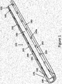
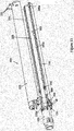
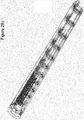
- FIGs 1 and 2 illustrate one embodiment of a bending strain relief (BSR) assembly 100 that includes a first elongated bending strain relief (BSR) member 110 ( Figure 1 ) that is configured to slidably attach and detach from a second elongated BSR member 120 identical to the first BSR member ( Figure 2 ) to limit the bending radius of an associated marine cable (not shown).
- the BSR assembly 100 includes a transition member or coupler 130 that supports the attachment of the first and second elongated BSR members 110, 120 as the BSR members are positioned along the cable.
- the BSR members 110, 120 can be made from an elastomer material, for example a polyurethane material or a polyurethane material with strengthening material such as carbon fibers or the like, although other materials that can withstand the rigors of the end use environment may be used without departing from the scope and intent of the present disclosure, and that include axially spaced, plural support members (that may or may not be interconnected by one or more elongated stiffness members) as will be described in greater detail below.
- an elastomer material for example a polyurethane material or a polyurethane material with strengthening material such as carbon fibers or the like, although other materials that can withstand the rigors of the end use environment may be used without departing from the scope and intent of the present disclosure, and that include axially spaced, plural support members (that may or may not be interconnected by one or more elongated stiffness members) as will be described in greater detail below.
- each elongated BSR member 110, 120 has an inner arcuate surface 160 that defines a circumferentially continuous inner perimeter portion of the assembly 100.
- the inner perimeter portion receives the marine cable therein.
- each of the BSR members 110, 120 has a proximal end 170 and a distal end 180 spaced from the proximal end 170.
- the arcuate surface 160 extends continuously along the bend limiting members 110, 120 and, in one embodiment, includes a half circle or generally C-shaped profile.
- BSR members 110, 120 once assembled, create a generally hollow sleeve-like component such that the inner arcuate surfaces 160 are aligned to form a cavity dimensioned to receive and support an outer perimeter surface of the cable.
- an outer surface 190 of the combined BSR members 110, 120 extends between the proximal 170 and distal ends 180 and has a generally arcuate or rounded profile.
- the BSR members 110, 120 have a generally cylindrical shaped cross-sectional profile so that the proximal end 170 is attached to the coupler 130 as the inner arcuate surfaces 160 can be generally aligned with the longitudinal inner surface of the coupler 130 and support, engage, or abut a perimeter surface of the cable (not shown).
- the coupler 130 is attached to the elongated BSR members 110, 120 along an interface surface 150 and can be made of a corrosion resistant metal. However, it is contemplated that other materials can be used to make the coupler 130.
- Plural support members 140a, 140b are provided at axially spaced locations along the first and second BSR members 110, 120, respectively.
- the support members 140a, 140b can be arranged internally of the bend limiter members 110, 120 (i.e., at least partially encased or encapsulated in the elastomer or polyurethane material that forms a body of the first and second BSR members) and the support members preferably have a generally C-shaped body profile that resembles the corresponding arcuate surfaces 160.
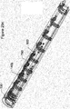
- FIGURE 1 illustrates eight (8) support members 140a that are distributed or axially spaced along the length of the first BSR member 110, although the particular number of support members may be varied without departing from the scope and intent of the present disclosure.
- the second elongated BSR member 120 also includes eight (8) support members 140b and is configured to complement the eight (8) support members 140a of the first BSR member 110.
- two or more support members 140a, 140b can be utilized in accordance with this disclosure.
- the range of bending motion of the BSR assembly 100 is reinforced by the elastomer material of the elongated BSR members 110, 120 and the number of support members 140a, 140b so that a total bending or curvature of the cable or array of cables, relative to the coupler 130, is limited by the surrounding first and second BSR members 110, 120.
- a distal support member 145a is located at the distal end 180 of the first BSR member 110 and is configured to align with a distal support member 145b of the second BSR member 120 and receive at least one pin 155 ( FIGURE 11 ) to secure or fasten the first and second BSR members 110, 120 in place about the cable and to prevent axial shifting relative to members 110 and 120 during bending, and as will be described in greater detail below.
- the plurality of rigid support members 140 are axially spaced apart and generally aligned along a common axis and the inner arcuate surfaces 160 of the first and second elongated BSR members 110, 120, respectively.
- the plurality of rigid support members 140a of the first elongated BSR member 110 are configured to axially align with the plurality of rigid support members 140b of the second elongated BSR member 120.
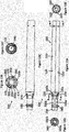
- the plurality of rigid support members 140a, 140b each include a first end 200 and a second end 210 on opposing sides of an inner arcuate surface 165 of each support member 140a, 140b.
- a protrusion member 220 extends from the first end 200 and a protrusion receiving member 230 is recessed from the second end 210 of each support member 140a, 140b.
- the protrusion members 220 and the protrusion receiving members 230 are configured to align along an edge surface 240 of both the first and second elongated BSR members 110, 120.
- the edge surface 240 includes a first surface 242 and a second surface 245 separate from the first surface 242 and is generally aligned on a common plane wherein the inner arcuate surface 160 is between the first surface 242 and the second surface 245.
- the protrusion members 220 extend from the first surface 242 of the edge surface 240 and the protrusion receiving members extend from the second surface 245 of the edge surface 240.
- the edge surface 240 is a planar surface and the first surface 242 is generally parallel to and spaced from the second surface 245.
- the arcuate inner surface 160 axially extends between the first side 242 and the second side 245 of the edge surface 240.
- the first and second elongated BSR members 110, 120 each include a channel 250 that extends between the proximal end 170 and the distal end 180 and is aligned with the plurality of protrusion receiving members 230 of the rigid support members 140a, 140b along the edge surface 240.
- the channel 250 is spaced radially from the arcuate inner surfaces 160 and is recessed from a first side 245 of the edge surface 240.
- the channel 250 is configured to simultaneously receive the plurality of protrusion members 220 from the support members 140a, 140b of the other of the first and second BSR members 110, 120.
- the first elongated BSR member 110 is a corresponding mirror equivalent to the second elongated BSR member 120.
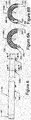
- distal support member 145b includes a first keyway 260 that is aligned with the protrusion member 220 along the first end 200 and a second keyway 270 that is aligned with the protrusion receiving member 230 along the second end 210.
- Each keyway extends substantially perpendicularly from the first end 200 and second end 210, respectively, to the outer surface 190 of each elongated BSR member 110, 120.
- the first and second keyways 260, 270 are configured to align with a corresponding keyway of a corresponding distal support member 145b such that the combined keyways extend from opposing outer surfaces 190 of each BSR member 110, 120.
- a fastener or pin can be received within each keyway to prevent disengagement of the first elongated BSR member 110 with the second BSR member 120.
- FIGURES 7 and 8 illustrate separate embodiments of the support members 140a, 140b.
- the support member 140a can be provided with protrusion member 220 and a protrusion receiving member 230 having different shaped profiles.
- the protrusion member 220 of FIGURE 7 has a hemispherical or mushroom-cap shaped head 280 and the protrusion receiving member 230 includes a correspondingly shaped profile 290 that is dimensioned to slidingly receive the hemispherical shaped head 280.
- the protrusion member 220 of FIGURE 8 has a tapered shaped head or key 310 and the protrusion receiving member 320 includes a correspondingly shaped profile or recess 320 that is dimensioned to slidingly receive the tapered shaped head 310.
- the profile shape of the protrusion member and protrusion receiving member can vary and the disclosure is not limiting and contemplates this corresponding feature.
- the support member can be provided with a plurality of apertures 300 spaced between the first end 200 and the second end 210 to provide additional structural integrity and to aid in the attachment of the support member 140a, 140b to the BSR members 110, 120. More particularly, the support members can be integrally formed within an inner cavity of the BSR members such that elastomeric material extends through the apertures 300. Also, in one embodiment, the support member apertures may receive, for example, at least one elongated stiffness member such as a wire, stranded nylon rope and/or helical rods or spring steel threaded rods extending through multiple support members to increase bending stiffness in the BSR assembly as will be discussed more fully below.
- elongated stiffness member such as a wire, stranded nylon rope and/or helical rods or spring steel threaded rods extending through multiple support members to increase bending stiffness in the BSR assembly as will be discussed more fully below.
- the BSR members 110, 120 are formed of cooperating portions such as symmetrical halves.
- the support members 140a, 140b act as cooperating receiving portions.
- the method of assembling the BSR assembly 100 to a marine cable includes steps that are designed to simplify maintenance of a marine cable array as it remains extended behind a vessel or when reeled in to the deck of a ship.
- the coupling or coupler 130 is provided along the perimeter of the marine cable, and the coupler 130 includes the interface surface 150. Initially, the first elongated BSR member 110 can be attached to the interface surface 150 of the coupling such that the inner arcuate surface 160 can support the marine cable (see FIGURES 11 and 12 ).
- the second elongated BSR member 120 is placed in a first axial position 310 relative to the first elongated BSR member 110 such that the inner arcuate surface 160 of the second elongated BSR member 120 can also receive the marine cable (see FIGURE 10 ).
- the second elongated BSR member 110 is positioned axially away from the coupler 130 such that the protrusion members 220 of the first elongated BSR member 110 can be subsequently inserted (such as by a sliding movement of one BSR member relative to the other BSR member) into the channels 250 of the second elongated BSR member 120 and the protrusion members 220 of the second elongated BSR member 120 can be inserted into the channels 250 of the first elongated BSR member 110.
- the protrusion members 220 and the protrusion receiving members 230 remain axially spaced from one another in this initial make-up position.
- At least one window or port 350 may also be provided in assembly 100, and preferably a port 350 is provided on each generally diametrical side.
- This port(s) preferably extends through the coupler 130 and allows a user to view the integrity of the cable, connection, etc., e.g., whether there is any corrosion, abrasion, and/or stress and fatigue failure of the assembly, cable, or reinforcement, etc.
- the ports 350 are sized to simultaneously serve the purpose of a flushing port through which seawater can easily pass, as well as being used as a view port or window, and therefore preferably extend through both the coupler and the polyurethane material of the BSR member.
- the first and second elongated BSR members 110, 120 are moved relative to one another from the offset, first axial position 310 to the aligned, second axial position 320 ( FIGURE 13A ) to connect the second elongated BSR member 120 to the first elongated BSR member 110 about the perimeter of the marine cable.
- the second elongated BSR member 120 can be attached to the interface surface 150 of the coupling 130.
- a sleeve member 330 can also be provided along the marine cable and be attached to the coupler 130.
- the sleeve member 330 is preferably rigidly attached to the cable and adapted or configured to prevent axial movement of the assembly 100 along the cable.
- each BSR member 110, 120 has a circumferential or arcuate length that generally corresponds to the partial circumferential extent of each BSR member portion, e.g., is generally C-shaped, so that when the portions are assembled together, cooperating C-shaped elastomeric members form a generally continuous resilient assembly that surrounds the perimeter of the cable.
- the assembly 100 is simplified. Less components are handled during assembly, inventory is reduced, and assembly accuracy is improved because the support members 140a, 140b (that include the protrusions 220 and protrusion receiving members 230) are integrated into the assembly 100.
- the BSR members 110, 120 preferably have a rounded outer contour surface 190 facing outwardly from the edge surface for selective engagement with a facing edge surface of the BSR member from the opposite side of the cable.
- respective ends 170, 180 of BSR members 110, 120 are free to articulate relative to the coupler 130 and sleeve member 330.
- the maximum extent of articulation is defined by the axial length of the BSR members and the number of support members therein.
- the BSR members 110, 120 allow the articulating movement of the cable, and when forces are relaxed, the members 110, 120 urge the cable toward an undeflected, generally linear orientation.
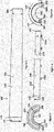
- FIGURES 13A-13F illustrate different views of the assembly 100 as fully assembled and without a cable through a passage 340 created by the inner arcuate surfaces 160 of the first and second elongated BSR members 110, 120.
- the coupler 130 can be assembled to the cable with a first coupler member 130a and a second coupler member 130b.
- the coupler members 130a, 130b are connected to one another in a similar fashion as the first and second elongated bend limiter members 110, 120.
- Each coupler member includes a protrusion member 350 and a corresponding protrusion receiving member 360 that are slidably attached to one another.
- the coupler 130 can include fastener receiving openings 370 that receive a respective fastener 375 to attach the coupler 130 to the sleeve member 330 along the cable. Additionally, it is contemplated that various alternative fastening arrangements may be employed.
- the sleeve member 330 can be assembled to the cable with a first sleeve member 330a and a second sleeve member 330b.
- Each of the sleeve members can be formed with a similar profile to the other, again, for ease of manufacture and assembly.
- Each sleeve member 330a, 330b includes at least a first pair of fastener openings 380 in which the openings are dimensioned to receive a threaded end of like fasteners therethrough.
- the relative fasteners can include a conventional fastener head that is configured to receive an associated assembly tool (not shown) and the fastener head is dimensioned so that the fastener may be fully received in the openings 370, 380 but is prevented from passing completely therethrough.
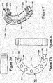
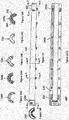
- FIGURES 14-14E illustrate comprehensive cross sectional portions of the second elongated BSR member 120.
- FIGURE 14 shows a BSR member that includes eight (8) support members 140b and includes a distal support member 145b.
- the distal support member 145b includes the first and second keyways 260, 270 that are configured to align with a corresponding keyway of a corresponding distal support member 145a such that the combined keyways extend from opposing outer surfaces 190 of each BSR member 110, 120.
- a fastener or pin can be received within each keyway to prevent disengagement of the first elongated BSR member 110 to the second elongated BSR member 120.
- first and second keyways 260, 270 are axially spaced from protrusion members 220 and protrusion receiving members 230.
- keyways such as 260, 270 may be integrated into multiple protrusion/protrusion receiving members 220, 230 for added strength.
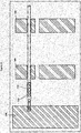
- FIGURE 14G illustrates the attachment between the second elongated BSR member 120 and the coupler 130. More particularly, the second coupler member 130b shares an interface surface 150 with the second elongated BSR member 120.
- the interface surface 150 includes a contoured portion of an outer surface of the second coupler 130b that is adapted to abut a contoured inner surface portion 390 of the second BSR member 120.
- the contoured inner surface portion 390 can have a profile shape that is in continuous contact with the interface surface 150 of the coupler ( FIGURE 14G ).
- the contoured inner surface 390 can include a profile shape with interrupted contact to the interface surface 150 that creates a labyrinth seal 400 with the coupler 130 ( FIGURE 11 ).
- the coupler members 130a, 130b are connected to one another in a similar fashion as the first and second elongated BSR members 110, 120.
- Each coupler member includes a protrusion member 350 and a corresponding protrusion receiving member 360 that are slidably attached to one another.
- the coupler 130 can include fastener receiving openings 370 that receive a respective fastener 375 to attach the coupler 130 to the sleeve member 330 along the cable. Additionally, it is contemplated that various fastening arrangements may be employed.
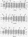
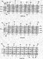
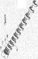
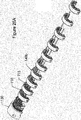
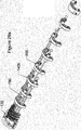
- FIGURES 15A through 15F illustrate schematic views of a layout of the axially spaced, arched support members 140 (now illustrated with reference numbers 410a-410f) with at least one elongated stiffness member 420.
- the elongated stiffness member 420 can be stranded nylon rope, helical rods, spring steel threaded rods, wire or other type of material that is received or threaded through the apertures 300 of various arched support members 410 in various configurations.
- Materials that are contemplated include synthetic polymers such as nylon with high elongation and strength properties or ultra-high-molecular-weight polyethylene (UHMWPE) such as Dyneema®, which exhibits some elongation and high strength typically approximately three to four times that of steel. Of course this does not preclude other materials that provide one or more of these same benefits, but are merely described herein as preferred materials.
- the body of the BSR members 110, 120 can be made from an elastomer material, for example a polyurethane material or a polyurethane material with strengthening material such as carbon fibers or the like.
- This material is not illustrated in FIGURES 15A-15F , 18-29b for ease of illustration; however, the stiffness members are preferably embedded in the elastomer or polyurethane material and anchored at various locations therein.
- the elongated stiffness members 420 are contemplated to be optionally used in either or both BSR members 110, 120 and can be threaded in various patterns through various ones of the support members 140a, 140b.
- FIGURES 15A-15F will identify commonly identified items with "a, b, c, d, e, f" designations.
- FIGURES 15A-15F illustrate BSR members 110a-110f, support members 410a-410f, apertures 300a-300f, elongated stiffness members 420a-420f, proximal support members 430a-430f, and distal support members 440a-440f, respectively.
- the proximal support members 430a-430f exist along the BSR member 110a-110f that is nearest to the coupler 130 of the BSR assembly 100.
- the distal support members 440a-440f are located at the distal end 180 of the BSR assembly 100 and may optionally include a keyway (not shown) as described above. Additionally, the distal support members 440a-440f are illustrated with five (5) apertures 300a-300f while the support members 410a-410f and proximal support members 430a-430f are illustrated to include eight (8) apertures 300a-300f. The size, amount and location of the apertures can of course be varied to accommodate various configurations of the elongated stiffness members to provide a stiffness strength that is desired by the BSR assembly, and should not be deemed to limit the scope and intent of the present disclosure.
- the elongated stiffness members 420a-420f can include termination points 450a-450f adjacent the apertures 300a-300f of a desired support member 410a-410f, distal support member 440a-440f, or proximal support member 430a-430f to prevent the elongated stiffness member from becoming disengaged from the support member.
- the termination point can be a simple structure such as a knot, or a separate conventional fastener such as a nut or compression fitting, or still another structure or arrangement that secures the elongated stiffness member(s) to one or more of the support members.
- the termination point can be adjusted by essentially varying the length of the elongated stiffness member between the support members to modify the bending strength and displacement of the BSR assembly in a desired manner.
- FIGURE 15A illustrates a first embodiment of the rigid support members 410a with a first, longer elongated stiffness member 420a 1 and a second, shorter elongated stiffness member 420a 2 .
- the first and second elongated stiffness members 420a 1 , 420a 2 are made of a stranded nylon rope that can be braided or twisted material.
- the elongated stiffness members 420a 1 , 420a 2 are about 3/8" diameter rope and together equal approximately 32 feet in length, although these dimensions are exemplary only and the dimensions may be varied without departing from the scope and intent of the present disclosure.
- the first elongated stiffness member 420a 1 includes a first termination point 450a 1 at the proximal support member 430a and is threaded through a plurality of substantially axially aligned apertures 300a of the plurality of support members 410a aligned thereon.
- the first elongated stiffness member 420a 1 includes a turn 460a 1 adjacent the aperture 300a of the support member 410a located adjacent distal support member 440a and is threaded through the plurality of axial aligned apertures 300a of the plurality of support members 410a positioned thereon.
- a second turn 460a 2 is adjacent the aperture 300a along the proximal support member 430a and the first elongated stiffness member 420a 1 is threaded through a separate plurality of axially aligned apertures 300a positioned thereon to a third turn 460a 3 adjacent the aperture 300a of the distal support member 440a.
- the first elongated stiffness member 420a 1 is threaded through the plurality of axially aligned apertures 300a back to the proximal support member 430a.
- turns 460a 4 and 460a 6 are adjacent the proximal support member 430a and turn 460a 5 is adjacent the distal support member 440a to define a generally serpentine path of the stiffness member through the apertures in the multiple support members.
- the first elongated stiffness member 420a 1 also includes a second termination point 450a 2 adjacent the distal support member 440a.
- the second elongated stiffness member 420a 2 is threaded through the plurality of axially aligned apertures 300a and includes a first termination point 450a 3 adjacent to the aperture of the proximal support member 430a and a second termination point 450a 4 at the aperture of the support member 410a that is located adjacent to the distal support member 440a.
- FIGURE 15B is a schematic plan view of a second embodiment of the rigid support members 410c of the BSR member 110c with an elongated stiffness member 420b.
- only one stiffness member is utilized and is threaded through the plurality of axially aligned apertures 300b and includes turns 460b 1 -460b 7 and termination points 450a 1 and 450a 2 positioned along the proximal support member 430b.
- Turns 460b 1 and 460b 7 are aligned along the support member 410b that is located approximately three support members inwardly from the distal support member 440b.
- Turns 460b 1 and 460b 7 are the outermost turns while turns 460b 2 , 460b 4 and 460b 6 are located along the proximal support member 430b while turns 460b 3 and 460b 5 are located along the distal support member 440b and are inwardly positioned thereon.
- the stiffness member extends through only some of the axially aligned openings of the multiple support member along some segments of the serpentine path and extends through all of the axially aligned openings of all of the multiple support members along other segments of the serpentine path.
- FIGURE 15C is a schematic plan view of a third embodiment of the rigid support members 410c of the BSR member 110c with an elongated stiffness member 420c made of nylon material.
- only one stiffness member 420 is used and is threaded through the plurality of axially aligned apertures 300c and includes turns 460c 1 -460c 5 and termination points 450c 1 and 450c 2 along the proximal support member 430c.
- Turn 460c 1 is aligned along the support member 410c that is located approximately one (1) support member inwardly from the distal support member 440c.
- Turns 460c 1 and 460c 5 are the outermost turns while turns 460c 2 , and 460c 4 are located along the proximal support member 430c and turn 460c 5 is located along the distal support member 440c.
- the outermost plurality of axially aligned apertures 300c remains vacant as elongated stiffness member 420c is threaded through the apertures positioned circumferentially inwardly therefrom.
- FIGURE 15D is a schematic plan view of a fourth embodiment of the rigid support members 410d of the BSR member 110d with a plurality of elongated stiffness members 420d 1 , 420d 2 and 420d 3 in yet another pattern.
- three (3) nylon rope stiffness members 420d 1 , 420d 2 and 420d 3 are threaded through the plurality of axially aligned apertures 300d of support members 410d and includes turns 460d 1 - 460d 5 and termination points 450d 1 -450d 6 .
- Termination points 450d 1 and 450d 2 are associated with elongated stiffness member 420d 1 and are aligned along the support member 410d that is located approximately one support member inwardly from the distal support member 440d.
- Turn 460d 1 is associated with elongated stiffness member 420d 1 and is the outermost turn located along the proximal support member 430d.
- Elongated stiffness member 420d 2 includes four turns, for example, where turns 460d 2 and 460d 4 are located along the distal support member 440d while turns 460c 3 and 460c 5 are located along the proximal support member 430d.
- Termination points 450d 3 and 450d 4 are associated with elongated stiffness member 420d 2 .
- Termination point 450d 3 is located along proximal support member 430d while termination point 450d 4 is located along distal support member 440d.
- the third elongated stiffness member 420d 3 includes no turns and is threaded through one of the outermost plurality of axially aligned apertures 300d.
- Termination point 450d 5 is positioned along the proximal support member 430d while termination point 450d 4 is positioned along the support member 410d that is located approximately one (1) support member inwardly from the distal support member 440d.
- this particular pattern is representative of a wide array of patterns that may be used depending on the final bending characteristics that are desired or required.
- FIGURE 15E is a schematic plan view of a fifth embodiment of the rigid support members 410e of the BSR member 110e with a plurality of helical rod-type elongated stiffness members 420e 1 , 420e 2 420e 3 and 420e 4 .
- Each of the elongated stiffness members includes two termination points and one interim turn.
- the turns 460e 1 , 460e 2 , 460e 3 and 460d 4 in this arrangement are disposed in the same manner along the proximal support member 430e.
- the elongated stiffness member 420e 1 is threaded through the plurality of axially aligned apertures 300e and terminates along the support member 410e that is located one support member inwardly of the distal support member 440e.
- Elongated stiffness members 420e 2 and 420e 3 are associated with turns 460e 2 , 460e 3 and terminate along the distal support member 440e.
- Elongated stiffness member 420e 4 includes staggered terminations wherein one termination is along the distal support member 440e and one termination is along the support member 410e that is located one (1) support member inwardly from the distal support member 440e. Again, this arrangement shows the variations that may be used with the stiffness members.
- FIGURE 15F is a schematic plan view of a sixth embodiment of the rigid support members 410f of the BSR member 110f with a plurality of spring steel threaded rod-type elongated stiffness members 420f 1 , 420f 2 , 420f 3 , 420f 4 and 420f 5 having a plurality of stop members such as threaded nuts 470f positioned thereon.
- the threaded nuts 470f can act as termination points along the proximal support member 430f and be spaced from the distal support member 440f. Additionally, the plurality of threaded nuts 470f can be spaced between the support members 410f at various positions to adjust the stiffness of the BSR member. As the BSR member bends, the threaded nuts abut against or lock onto the support members 410f to restrict further bending.
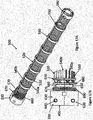
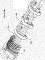
- FIGURES 16A and 17 illustrate a skeletal perspective view of another embodiment of a BSR assembly 500 with a first elongated BSR member 510 attached to a second elongated BSR member 520 and connected to a coupler 530.
- the coupler 530 supports the attachment of the first and second elongated BSR members 510, 520 as the BSR members are positioned along an associated elongated member such as a cable (not shown).
- the BSR members 510, 520 include a first elongated stiffness member 540a and a second elongated stiffness member 540b that are threaded through a plurality of axially aligned apertures 550 spaced about arched shaped support members 560 and extend between a proximal support member 570 and a distal support member 580.
- the first elongated stiffness member 540a is associated with the first elongated BSR member 510 and is made, for example, of a stranded material such as nylon rope.
- the second elongated stiffness member 540b is associated with the second elongated BSR member 520 is, for example, a helical rod, spring steel threaded rod, wire or other type of material.
- the elongated stiffness members 540a, 540b can be made of the same material as illustrated in FIGURE 17 .
- the elongated stiffness members 540a, 540b includes turns and termination points at various locations along the support members 560, proximal support members 570 and distal support members 580 of both the first and second elongated BSR members 510, 520.
- the elongated stiffness members 540a, 540b are configured in a circumferential pattern that adapts to the arched shape support members 560 as the stiffness members extend lengthwise along the BSR assembly 500.
- FIGURES 16B and 17B illustrate the coupler 530 attached to the first and second BSR members 510, 520 at a proximal end thereof.
- the coupler 530 includes a first end 600 and an opposite, second end 610 with a longitudinal inner surface that extends from the first end to the second end.
- the coupler has a curved profile or inner arcuate surface that aligns with the inner arcuate surface of the BSR members.
- the coupler 530 includes a first portion 620 that is directly attached to the first elongated BSR member 510 and a second portion 630 that is directly attached to the second elongated BSR member 520.
- the first portion 620 and first extension member 650 are identical to the second portion 630 and the second extension member 660 to allow for ease of manufacturing.
- the coupler 530 includes a fastener aperture 640 dimensioned to receive a conventional fastener or pin to axially lock BSR member 510, 520 relative to the housing flange member 330c, 330d ( Figure 10 ).
- First and second extension members 650, 660 are provided to attach the first and second portions 620, 630 to the proximal support members 570, respectively.
- the first and second extension members 650, 660 include a radial base 670 that abuts against the second side 610 of the coupler 630. Further, the radial base 670 preferably has a smaller radial profile dimension than the coupler 530 and can define an annular groove 690.
- the first and second extension members 650, 660 can optionally include a radial shoulder 680 that is provided between the radial base 670 and the proximal support member 570.
- the radial base 670 and the radial shoulder 680 are adapted to be covered by the elastomer material described above.
- FIGURES 18-29c Embodiments disclosing various orientations of the elongated stiffness members are discussed in FIGURES 18-29c .
- Each embodiment disclosed is contemplated to be potted within a cured polyurethane material.
- FIGURE 18 is an enlarged schematic view of a portion of the BSR assembly with the plurality of elongated stiffness members as rope loops 700.
- the rope loops are loosely coupled between a plurality of support members 140 that are provided at axially spaced locations along the first and second BSR members 110, 120, respectively.
- the rope loops 700 are terminated at the coupler 130 through an eyehole 710 or can optionally be terminated at the coupler with known conventional fasteners.
- the rope can be made from nylon or a polymer such as polypropylene or Dyneema® brand rope or still other conventional rope material.
- the rope loops 700 are threaded through apertures within the support members 140 and connected via knots or other conventional means for joining rope ends such as clips, fasteners, etc.
- the rope can be 3/16" diameter measurement but this disclosure is not limiting.
- FIGURE 19 is an enlarged schematic view of a portion of the BSR assembly with the plurality of elongated stiffness members as composite rods 710.
- the composite rods 710 are terminated at the coupler 130 through a conventional fastener such as a hook and screw.
- the rods 710 are threaded through apertures of the support members 140 and have various lengths in a generally staggered orientation.
- the composite rods 710 are generally a composite material such as fiberglass that are generally solid with a sand blasted surface that is primed, although other materials may be used without departing from the scope and intent of the present disclosure.
- the rods 710 are loosely fed through the stiffness members 140 to allow for various strengths that resist bending of the assembly.
- the rods can have a helical grip 715 that extends along the rod from the connection to the coupler 130 to offer additional strength at the connection point to the coupler 130.
- the helical grip 715 can be multiple strands of wire that are wound around the rod in various arrangements and in a manner generally known in the art of gripping or terminating cables.
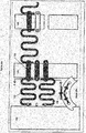
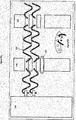
- FIGURE 20a is an enlarged schematic view of a portion of the BSR assembly with the plurality of elongated stiffness members as spring sections 720 and coupling links 725.
- the coupling links 725 are preferably placed within apertures of the rigid support members 140 and include eye holes or similar securing structure for receiving an end of the spring sections 720 therein.
- the coupling links 725 are generally flat for receipt through the support member apertures with the securing structure accessible at opposite ends of the coupling links when disposed in the aperture while the spring sections 720 are a serpentine shaped wire having, for example, 0.188 gauge wire that is hardened to about 220 kpsi.
- the spring sections 720 can be attached to one another through the coupling links 724 and have various arrangements within the assembly.
- the spring sections 720 and coupling links 725 can be adapted to generally follow the C shape contour of the support members 140 ( FIGURE 20b ). Additionally, there can be a second layer 730 of spring sections and coupling links that are placed over the top of the other spring sections, e.g., as seen Figure 20b , two of the springs are generally angled relative to one another from an intermediate radial position, while an additional layer(s) of spring(s) can be used at a different radial location (shown here as an outer radial location).
- FIGURE 21 is an enlarged schematic view of a portion of the BSR assembly with the plurality of elongated stiffness members as stiffness rods 740.
- the stiffness rods can be stiff rods made of polyurethane material or other suitably stiff material of similar or various lengths that are arranged through the rigid support members 140, for example, in staggered lengths whereby various bending capabilities can be adequately addressed.
- the stiffness rods 740 are not anchored to the coupling 130 but are frictionally bonded to the rigid support members 140 through apertures.
- FIGURE 22a is an enlarged schematic view of a portion of the BSR assembly with the plurality of elongated stiffness members as helical rods 750.
- the helical rods 750 can be threaded through apertures of the support members 140 or connected to rod connectors 755.
- the helical rods are sand blasted and primed for bonding and include, for example, a pitch length of 1.5" with a gauge between about 0.137 to 0.188 wire although other dimensional arrangements are also contemplated.
- the helical rods can include right angle termination points at the coupler 130 and/or support members 140 wherein the rods are hooked thereon by the rod bent to a right angle through an eyebolt or aperture, or fed through radially extending slots that communicate with the support member apertures (see FIGURE 22b ).
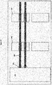
- FIGURE 23 is an enlarged schematic view of a portion of the BSR assembly with the plurality of elongated stiffness members as threaded rods 760.
- the threaded rods 760 are preferably anchored to the coupler 130 (e.g., threadedly received therein) by a fastener or nut 765.
- the rods have a 1 ⁇ 4" diameter made with high tensile stiffness metal, although other dimensions and materials may be used.
- the threaded rods 760 can have similar or varied lengths and placed in staggered orientation through the apertures of the support members 140 to address desired bending needs of the intended end use. In the illustrated arrangement, the threaded rods are dimensioned for free receipt through the support members.
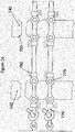
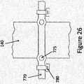
- FIGURE 24 is an enlarged schematic view of a portion of the BSR assembly with the plurality of elongated stiffness members as linear locked rope 770.
- the rope 770 can be made from 3/16" diameter Dyneema® brand material, for example, and threaded through apertures of the support members 140.
- Steel balls 775 and strap locks 780 such as nylon Tylok (TM) can be used as one example of an axial fastener or restraining assembly to restrain the rope within the support member, i.e., at opposite axial ends of the support members.
- the apertures of the support member preferably include a countersunk profile 785 to accommodate or receive the spherical shape of the balls 775 therein that are used as termination points to lock the rope at either side of the support member 140.
- This orientation preferably places the stiffness members in tension relative to the support members and can be arranged to modify the bending strength/resistance of the assembly. Likewise, the arrangement can be easily assembled on site.
- a knot or fastener is provided at one end to dead end or secure the rope to the metal adapter, for example through the openings in the eye bolts as illustrated.
- FIGURE 25 is an enlarged schematic view of a portion of the BSR assembly with the plurality of elongated stiffness members having locked rope 770 threaded through various apertures of the support members 140.
- This arrangement contemplates various weaving patterns that include the steel ball 775 and strap lock 780 rope configurations generally described in connection with the embodiment of Figure 24 , although selected aspects of the weaving concept can be used with still other embodiments.
- FIGURE 26 is an enlarged view of the locked rope 770 of elongated stiffness member as also illustrated by FIGURES 24 and 25 .
- FIGURES 27A and 27B provide an outline view of the second elongated BSR member with the plurality of rigid support members and a plurality of elongated stiffness members shown as composite rods 710 as illustrated in FIGURE 19 and stiffness rods 740 as illustrated in FIGURE 21 .
- the composite rods 710 are loosely fed through the stiffness members 140 to allow for various strengths that resist bending of the assembly. Depending on the number, placement, stiffness, etc., of the individual rods, the bending stiffness of the assembly can be suitably altered as desired.
- the helical grip 715 extends along the rod from the coupler 130 to offer additional strength at the connection point to the coupler 130.
- the helical grip 715 can be multiple strands of wire that are wound around the rod in various arrangements.
- the stiffness rods 740 are also provided in this embodiment illustrating that one or more of the concepts from various ones of the embodiments can be used in various combinations.
- the rods 740 are made of polyurethane material of various lengths that are arranged in staggered relation through the rigid support members 140.
- the stiffness rods 740 are not anchored to the coupling 130 but are frictionally bonded to the rigid support members 140 through apertures, although in other instances, the rods may or may not be anchored.
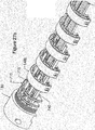
- FIGURES 28A , 28B 28C illustrate a perspective outline view of the second elongated BSR member with the plurality of rigid support members 140b and a plurality of elongated stiffness members as composite rods 710.
- FIGURE 28C illustrates the assembly prior being and as encapsulated in an elastomer such as polyurethane.
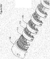
- FIGURE 29A and 29B outline views of the second elongated BSR member with the plurality of rigid support members 140b and a plurality of elongated stiffness members as stiffener rods 790 with locks 800 positioned along various support members.
- the stiffener rods 790 have various lengths wherein the locks 800 are positioned at various support members 140b wherein the rods are freely placed within the apertures of the support member and rigidly attached to the support member 140b having the lock 800.
- This arrangement varies the interaction of tension and compression by the length of the rods 790 and the compression of the elastomer encapsulation.
- FIGURE 29C illustrates the assembly as it is encapsulated in an elastomer such as polyurethane.
Landscapes
- Chemical & Material Sciences (AREA)
- Engineering & Computer Science (AREA)
- Combustion & Propulsion (AREA)
- Mechanical Engineering (AREA)
- Ocean & Marine Engineering (AREA)
- Laying Of Electric Cables Or Lines Outside (AREA)
Claims (12)
- Ensemble réducteur de tension de flexion (BSR) (100) qui limite la tension de flexion et le rayon d'un câble marin associé, l'ensemble de BSR comprenant :un coupleur (130) ayant une première extrémité et une seconde extrémité opposée avec une surface interne longitudinale qui s'étend de la première extrémité à la seconde extrémité ;un premier élément de BSR allongé (110) ayant une extrémité proximale (170) et une extrémité distale (180) espacée de l'extrémité proximale avec une première surface arquée interne (160) qui s'étend entre l'extrémité proximale et l'extrémité distale, le premier élément de BSR étant dimensionné pour se fixer au coupleur le long d'une partie d'une surface d'interface (150) le long de la seconde extrémité du coupleur et de l'extrémité proximale du premier élément de BSR de sorte que la première surface arquée interne est alignée avec la surface interne longitudinale du coupleur ; etun second élément de BSR allongé (120) ayant une extrémité proximale (170) et une extrémité distale (180) espacée de l'extrémité proximale avec une surface arquée interne (160), le second BSR étant dimensionné pour se fixer au coupleur le long d'une partie de la surface d'interface le long de la seconde extrémité du coupleur et de l'extrémité proximale du second élément de BSR de sorte que la surface arquée interne est alignée avec la surface interne longitudinale du coupleur ;dans lequel le câble marin associé est configuré pour être supporté à l'intérieur d'une surface interne longitudinale et les surfaces arquées internes des premier et second éléments de BSR allongés afin de limiter la tension de flexion et le rayon du câble en modifiant des niveaux de résistance à la flexion ; etl'ensemble de BSR (100) comprend en outre au moins un élément de rigidité allongé (420) dans chacun des premier et second éléments de BSR allongés (110, 120) pour modifier la rigidité de l'ensemble de BSR ;caractérisé en ce que :les éléments de rigidité allongés (420, 720) définissent une trajectoire en serpentin.
- Ensemble de BSR (100) selon la revendication 1, dans lequel les premier et second éléments de BSR (110, 120) comprennent une pluralité d'éléments de support rigides (140a, 140b) généralement alignés le long d'un axe commun et les surfaces arquées internes (160) des premier et second éléments de BSR allongés, les éléments de supports étant disposés en relation axialement espacée.
- Ensemble de BSR (100) selon la revendication 1 ou 2, dans lequel le au moins un élément de rigidité allongé (420) passe longitudinalement à travers les ouvertures (300) dans les éléments de support (410) pour modifier la rigidité de l'ensemble de BSR.
- Ensemble de BSR (100) selon l'une quelconque des revendications précédentes, dans lequel les ondes individuelles de l'élément de rigidité (420, 720) s'étendent dans une direction perpendiculaire à la direction axiale.
- Ensemble de BSR (100) selon l'une quelconque des revendications précédentes, dans lequel les éléments de rigidité allongés (420) sont disposés sur plusieurs couches radialement espacées dans les éléments de BSR (110, 120).
- Ensemble de BSR (100) selon l'une quelconque des revendications précédentes, dans lequel une première extrémité de l'élément de rigidité allongé (720) est assemblée au coupleur (130) ou à un élément de support rigide (140), et une seconde extrémité dudit élément de rigidité allongé est assemblée à un élément de support rigide (140).
- Ensemble de BSR (100) selon l'une quelconque des revendications 2 à 6, dans lequel les éléments de rigidité allongés (720) sont assemblés entre eux dans une direction axiale en couplant des liaisons (725) s'étendant à travers les ouvertures (300) dans les éléments de support rigides (140).
- Ensemble de BSR (100) selon l'une quelconque des revendications précédentes, dans lequel la pluralité desdits éléments de rigidité allongés (420, 740) ont des dimensions axiales différentes.
- Ensemble de BSR (100) selon l'une quelconque des revendications précédentes, dans lequel ledit au moins un élément de rigidité allongé (420) est réalisé à partir de fil.
- Ensemble de BSR (100) selon l'une quelconque des revendications précédentes, dans lequel lesdits premier et second éléments de BSR (110, 120) sont réalisés à partir d'un matériau élastomère.
- Ensemble de BSR (100) selon l'une quelconque des revendications précédentes, dans lequel ledit au moins un élément de rigidité allongé (420) est réalisé à partir d'une tige hélicoïdale.
- Ensemble de BSR (100) selon l'une quelconque des revendications précédentes, dans lequel ledit au moins un élément de rigidité allongé (420) est réalisé à partir de corde.
Priority Applications (1)
| Application Number | Priority Date | Filing Date | Title |
|---|---|---|---|
| EP18165522.6A EP3375703B1 (fr) | 2012-11-02 | 2013-11-04 | Ensemble réducteur de tension de flexion amélioré pour câbles marins comprenant au moins un élément de rigidité allongé |
Applications Claiming Priority (3)
| Application Number | Priority Date | Filing Date | Title |
|---|---|---|---|
| US201261721905P | 2012-11-02 | 2012-11-02 | |
| US201361814661P | 2013-04-22 | 2013-04-22 | |
| PCT/US2013/068316 WO2014071305A2 (fr) | 2012-11-02 | 2013-11-04 | Ensemble réducteur de tension de flexion amélioré pour câbles marins comprenant au moins un élément de rigidité allongé |
Related Child Applications (1)
| Application Number | Title | Priority Date | Filing Date |
|---|---|---|---|
| EP18165522.6A Division EP3375703B1 (fr) | 2012-11-02 | 2013-11-04 | Ensemble réducteur de tension de flexion amélioré pour câbles marins comprenant au moins un élément de rigidité allongé |
Publications (3)
| Publication Number | Publication Date |
|---|---|
| EP2914484A2 EP2914484A2 (fr) | 2015-09-09 |
| EP2914484A4 EP2914484A4 (fr) | 2016-08-10 |
| EP2914484B1 true EP2914484B1 (fr) | 2018-04-04 |
Family
ID=50628262
Family Applications (2)
| Application Number | Title | Priority Date | Filing Date |
|---|---|---|---|
| EP13851507.7A Not-in-force EP2914484B1 (fr) | 2012-11-02 | 2013-11-04 | Ensemble réducteur de tension de flexion amélioré pour câbles marins comprenant au moins un élément de rigidité allongé |
| EP18165522.6A Active EP3375703B1 (fr) | 2012-11-02 | 2013-11-04 | Ensemble réducteur de tension de flexion amélioré pour câbles marins comprenant au moins un élément de rigidité allongé |
Family Applications After (1)
| Application Number | Title | Priority Date | Filing Date |
|---|---|---|---|
| EP18165522.6A Active EP3375703B1 (fr) | 2012-11-02 | 2013-11-04 | Ensemble réducteur de tension de flexion amélioré pour câbles marins comprenant au moins un élément de rigidité allongé |
Country Status (3)
| Country | Link |
|---|---|
| US (1) | US11142288B2 (fr) |
| EP (2) | EP2914484B1 (fr) |
| WO (1) | WO2014071305A2 (fr) |
Families Citing this family (4)
| Publication number | Priority date | Publication date | Assignee | Title |
|---|---|---|---|---|
| US9499236B1 (en) * | 2014-04-09 | 2016-11-22 | Pea Marine, LLC | Equipment protection sleeves |
| EP3249430A1 (fr) | 2015-03-26 | 2017-11-29 | CGG Services SA | Dispositif de protection de câble à montage rapide utilisable dans des sondages marins |
| US10625825B1 (en) | 2017-07-24 | 2020-04-21 | Line Defenders, LLC | Chafe guard assembly for a watercraft mooring line |
| US10323353B2 (en) * | 2017-10-03 | 2019-06-18 | Makani Technologies Llc | Faired tether systems with internal support structure in the faired tether |
Family Cites Families (13)
| Publication number | Priority date | Publication date | Assignee | Title |
|---|---|---|---|---|
| NL74372C (fr) * | 1942-04-21 | |||
| DE2236854C2 (de) * | 1972-07-27 | 1983-12-29 | kabelmetal electro GmbH, 3000 Hannover | Abstandshalter für gasisolierte Hochspannungskabel |
| NO147538C (no) * | 1980-12-22 | 1983-04-27 | Standard Tel Kabelfab As | Boeyeavlastning med variabel stivhet. |
| US4469392A (en) * | 1982-03-19 | 1984-09-04 | Mobil Oil Corporation | Ocean bottom seismic cable connector |
| US4502189A (en) * | 1982-06-21 | 1985-03-05 | Morris Coupling Company | Coupling with outrigger parts |
| US5062085A (en) * | 1984-02-21 | 1991-10-29 | Andrews Jr Daniel E | Vibration isolation module for towed seismic arrays |
| US5274603A (en) * | 1991-07-29 | 1993-12-28 | Shell Oil Company | Marine seismic cable section assembly |
| US5367499A (en) * | 1993-09-23 | 1994-11-22 | Whitehall Corporation | Vibration isolation module for towed hydrophone streamer |
| US5707252A (en) | 1995-10-10 | 1998-01-13 | Alden Products Company | Snap-together x-ray cable coupling nut assembly |
| US5710851A (en) | 1995-11-06 | 1998-01-20 | Amphenol Corporation | Strain relief system for a fiber optic connector |
| US6262944B1 (en) * | 1999-02-22 | 2001-07-17 | Litton Systems, Inc. | Solid fill acoustic array |
| US6619697B2 (en) * | 2000-12-27 | 2003-09-16 | Nkf Kabel B.V. | Y-branch splittable connector |
| US20130270414A1 (en) * | 2012-04-16 | 2013-10-17 | Shure Acquisition Holdings, Inc. | Shock mounting apparatus and method for reducing amount of shock |
-
2013
- 2013-11-04 EP EP13851507.7A patent/EP2914484B1/fr not_active Not-in-force
- 2013-11-04 EP EP18165522.6A patent/EP3375703B1/fr active Active
- 2013-11-04 WO PCT/US2013/068316 patent/WO2014071305A2/fr active Application Filing
- 2013-11-04 US US14/440,134 patent/US11142288B2/en active Active
Non-Patent Citations (1)
| Title |
|---|
| None * |
Also Published As
| Publication number | Publication date |
|---|---|
| EP3375703B1 (fr) | 2019-12-25 |
| EP2914484A4 (fr) | 2016-08-10 |
| EP3375703A1 (fr) | 2018-09-19 |
| WO2014071305A3 (fr) | 2014-08-21 |
| EP2914484A2 (fr) | 2015-09-09 |
| US11142288B2 (en) | 2021-10-12 |
| US20150266546A1 (en) | 2015-09-24 |
| WO2014071305A2 (fr) | 2014-05-08 |
Similar Documents
| Publication | Publication Date | Title |
|---|---|---|
| EP2914484B1 (fr) | Ensemble réducteur de tension de flexion amélioré pour câbles marins comprenant au moins un élément de rigidité allongé | |
| FI59470B (fi) | Dragfjaederanordning | |
| US7059091B2 (en) | Tension member | |
| US6612370B1 (en) | Composite hybrid riser | |
| US20100257835A1 (en) | Chain link | |
| EP3245331B1 (fr) | Élément d'amarrage | |
| EP3178988B1 (fr) | Dispositif et procédé de fabrication d'un câble de traction, et d'un câble de traction | |
| JP2022531289A (ja) | 分割区分け曲げ抑制器 | |
| CN103154566B (zh) | 用于系泊缆绳的自对准索节 | |
| US9923355B2 (en) | Termination of strength members of deep water cables | |
| US20050169702A1 (en) | End termination means in a tension leg and a coupling for use between such an end termination and connecting point | |
| US6385928B1 (en) | Tension member | |
| US6938571B1 (en) | Floating structure having anchor lines comprising damping means | |
| US20040111987A1 (en) | End termination of tension leg | |
| GB2613801A (en) | Bend resistor | |
| EP3625118B1 (fr) | Bouée comprenant une armature légère pour transfert de poids | |
| WO2016151044A1 (fr) | Protection d'amarres fibreuses | |
| EP4386175A1 (fr) | Limiteur de courbure | |
| EP4118360B1 (fr) | Agencement de limitation de courbure de câble et combinaison d'un agencement de limitation de courbure de câble avec un câble, un ancrage, une unité pince de compactage et un tuyau creux | |
| KR101626844B1 (ko) | 로프 스톱퍼 및 이의 제조 방법 | |
| RU2634604C2 (ru) | Устройство для соединения первого и второго протяженных элементов | |
| HU197422B (en) | Flexible technical hose mountable from several parts but deforming slightly under the effect of internal overpressure |
Legal Events
| Date | Code | Title | Description |
|---|---|---|---|
| PUAI | Public reference made under article 153(3) epc to a published international application that has entered the european phase |
Free format text: ORIGINAL CODE: 0009012 |
|
| 17P | Request for examination filed |
Effective date: 20150601 |
|
| AK | Designated contracting states |
Kind code of ref document: A2 Designated state(s): AL AT BE BG CH CY CZ DE DK EE ES FI FR GB GR HR HU IE IS IT LI LT LU LV MC MK MT NL NO PL PT RO RS SE SI SK SM TR |
|
| AX | Request for extension of the european patent |
Extension state: BA ME |
|
| DAX | Request for extension of the european patent (deleted) | ||
| A4 | Supplementary search report drawn up and despatched |
Effective date: 20160707 |
|
| RIC1 | Information provided on ipc code assigned before grant |
Ipc: B63B 21/04 20060101AFI20160701BHEP |
|
| GRAP | Despatch of communication of intention to grant a patent |
Free format text: ORIGINAL CODE: EPIDOSNIGR1 |
|
| INTG | Intention to grant announced |
Effective date: 20171027 |
|
| GRAS | Grant fee paid |
Free format text: ORIGINAL CODE: EPIDOSNIGR3 |
|
| GRAA | (expected) grant |
Free format text: ORIGINAL CODE: 0009210 |
|
| AK | Designated contracting states |
Kind code of ref document: B1 Designated state(s): AL AT BE BG CH CY CZ DE DK EE ES FI FR GB GR HR HU IE IS IT LI LT LU LV MC MK MT NL NO PL PT RO RS SE SI SK SM TR |
|
| REG | Reference to a national code |
Ref country code: GB Ref legal event code: FG4D |
|
| REG | Reference to a national code |
Ref country code: CH Ref legal event code: EP |
|
| REG | Reference to a national code |
Ref country code: AT Ref legal event code: REF Ref document number: 985302 Country of ref document: AT Kind code of ref document: T Effective date: 20180415 |
|
| REG | Reference to a national code |
Ref country code: DE Ref legal event code: R096 Ref document number: 602013035533 Country of ref document: DE |
|
| REG | Reference to a national code |
Ref country code: IE Ref legal event code: FG4D |
|
| REG | Reference to a national code |
Ref country code: NL Ref legal event code: FP |
|
| REG | Reference to a national code |
Ref country code: NO Ref legal event code: T2 Effective date: 20180404 |
|
| REG | Reference to a national code |
Ref country code: LT Ref legal event code: MG4D |
|
| REG | Reference to a national code |
Ref country code: FR Ref legal event code: PLFP Year of fee payment: 6 |
|
| PG25 | Lapsed in a contracting state [announced via postgrant information from national office to epo] |
Ref country code: PL Free format text: LAPSE BECAUSE OF FAILURE TO SUBMIT A TRANSLATION OF THE DESCRIPTION OR TO PAY THE FEE WITHIN THE PRESCRIBED TIME-LIMIT Effective date: 20180404 Ref country code: LT Free format text: LAPSE BECAUSE OF FAILURE TO SUBMIT A TRANSLATION OF THE DESCRIPTION OR TO PAY THE FEE WITHIN THE PRESCRIBED TIME-LIMIT Effective date: 20180404 Ref country code: SE Free format text: LAPSE BECAUSE OF FAILURE TO SUBMIT A TRANSLATION OF THE DESCRIPTION OR TO PAY THE FEE WITHIN THE PRESCRIBED TIME-LIMIT Effective date: 20180404 Ref country code: ES Free format text: LAPSE BECAUSE OF FAILURE TO SUBMIT A TRANSLATION OF THE DESCRIPTION OR TO PAY THE FEE WITHIN THE PRESCRIBED TIME-LIMIT Effective date: 20180404 Ref country code: AL Free format text: LAPSE BECAUSE OF FAILURE TO SUBMIT A TRANSLATION OF THE DESCRIPTION OR TO PAY THE FEE WITHIN THE PRESCRIBED TIME-LIMIT Effective date: 20180404 Ref country code: FI Free format text: LAPSE BECAUSE OF FAILURE TO SUBMIT A TRANSLATION OF THE DESCRIPTION OR TO PAY THE FEE WITHIN THE PRESCRIBED TIME-LIMIT Effective date: 20180404 Ref country code: BG Free format text: LAPSE BECAUSE OF FAILURE TO SUBMIT A TRANSLATION OF THE DESCRIPTION OR TO PAY THE FEE WITHIN THE PRESCRIBED TIME-LIMIT Effective date: 20180704 |
|
| PG25 | Lapsed in a contracting state [announced via postgrant information from national office to epo] |
Ref country code: LV Free format text: LAPSE BECAUSE OF FAILURE TO SUBMIT A TRANSLATION OF THE DESCRIPTION OR TO PAY THE FEE WITHIN THE PRESCRIBED TIME-LIMIT Effective date: 20180404 Ref country code: RS Free format text: LAPSE BECAUSE OF FAILURE TO SUBMIT A TRANSLATION OF THE DESCRIPTION OR TO PAY THE FEE WITHIN THE PRESCRIBED TIME-LIMIT Effective date: 20180404 Ref country code: GR Free format text: LAPSE BECAUSE OF FAILURE TO SUBMIT A TRANSLATION OF THE DESCRIPTION OR TO PAY THE FEE WITHIN THE PRESCRIBED TIME-LIMIT Effective date: 20180705 Ref country code: HR Free format text: LAPSE BECAUSE OF FAILURE TO SUBMIT A TRANSLATION OF THE DESCRIPTION OR TO PAY THE FEE WITHIN THE PRESCRIBED TIME-LIMIT Effective date: 20180404 |
|
| REG | Reference to a national code |
Ref country code: AT Ref legal event code: MK05 Ref document number: 985302 Country of ref document: AT Kind code of ref document: T Effective date: 20180404 |
|
| PG25 | Lapsed in a contracting state [announced via postgrant information from national office to epo] |
Ref country code: PT Free format text: LAPSE BECAUSE OF FAILURE TO SUBMIT A TRANSLATION OF THE DESCRIPTION OR TO PAY THE FEE WITHIN THE PRESCRIBED TIME-LIMIT Effective date: 20180806 |
|
| REG | Reference to a national code |
Ref country code: DE Ref legal event code: R097 Ref document number: 602013035533 Country of ref document: DE |
|
| PG25 | Lapsed in a contracting state [announced via postgrant information from national office to epo] |
Ref country code: AT Free format text: LAPSE BECAUSE OF FAILURE TO SUBMIT A TRANSLATION OF THE DESCRIPTION OR TO PAY THE FEE WITHIN THE PRESCRIBED TIME-LIMIT Effective date: 20180404 Ref country code: DK Free format text: LAPSE BECAUSE OF FAILURE TO SUBMIT A TRANSLATION OF THE DESCRIPTION OR TO PAY THE FEE WITHIN THE PRESCRIBED TIME-LIMIT Effective date: 20180404 Ref country code: SK Free format text: LAPSE BECAUSE OF FAILURE TO SUBMIT A TRANSLATION OF THE DESCRIPTION OR TO PAY THE FEE WITHIN THE PRESCRIBED TIME-LIMIT Effective date: 20180404 Ref country code: EE Free format text: LAPSE BECAUSE OF FAILURE TO SUBMIT A TRANSLATION OF THE DESCRIPTION OR TO PAY THE FEE WITHIN THE PRESCRIBED TIME-LIMIT Effective date: 20180404 Ref country code: CZ Free format text: LAPSE BECAUSE OF FAILURE TO SUBMIT A TRANSLATION OF THE DESCRIPTION OR TO PAY THE FEE WITHIN THE PRESCRIBED TIME-LIMIT Effective date: 20180404 Ref country code: RO Free format text: LAPSE BECAUSE OF FAILURE TO SUBMIT A TRANSLATION OF THE DESCRIPTION OR TO PAY THE FEE WITHIN THE PRESCRIBED TIME-LIMIT Effective date: 20180404 |
|
| PLBE | No opposition filed within time limit |
Free format text: ORIGINAL CODE: 0009261 |
|
| STAA | Information on the status of an ep patent application or granted ep patent |
Free format text: STATUS: NO OPPOSITION FILED WITHIN TIME LIMIT |
|
| PG25 | Lapsed in a contracting state [announced via postgrant information from national office to epo] |
Ref country code: IT Free format text: LAPSE BECAUSE OF FAILURE TO SUBMIT A TRANSLATION OF THE DESCRIPTION OR TO PAY THE FEE WITHIN THE PRESCRIBED TIME-LIMIT Effective date: 20180404 Ref country code: SM Free format text: LAPSE BECAUSE OF FAILURE TO SUBMIT A TRANSLATION OF THE DESCRIPTION OR TO PAY THE FEE WITHIN THE PRESCRIBED TIME-LIMIT Effective date: 20180404 |
|
| 26N | No opposition filed |
Effective date: 20190107 |
|
| PG25 | Lapsed in a contracting state [announced via postgrant information from national office to epo] |
Ref country code: SI Free format text: LAPSE BECAUSE OF FAILURE TO SUBMIT A TRANSLATION OF THE DESCRIPTION OR TO PAY THE FEE WITHIN THE PRESCRIBED TIME-LIMIT Effective date: 20180404 |
|
| REG | Reference to a national code |
Ref country code: CH Ref legal event code: PL |
|
| PG25 | Lapsed in a contracting state [announced via postgrant information from national office to epo] |
Ref country code: LU Free format text: LAPSE BECAUSE OF NON-PAYMENT OF DUE FEES Effective date: 20181104 Ref country code: MC Free format text: LAPSE BECAUSE OF FAILURE TO SUBMIT A TRANSLATION OF THE DESCRIPTION OR TO PAY THE FEE WITHIN THE PRESCRIBED TIME-LIMIT Effective date: 20180404 |
|
| REG | Reference to a national code |
Ref country code: BE Ref legal event code: MM Effective date: 20181130 |
|
| REG | Reference to a national code |
Ref country code: IE Ref legal event code: MM4A |
|
| PG25 | Lapsed in a contracting state [announced via postgrant information from national office to epo] |
Ref country code: CH Free format text: LAPSE BECAUSE OF NON-PAYMENT OF DUE FEES Effective date: 20181130 Ref country code: LI Free format text: LAPSE BECAUSE OF NON-PAYMENT OF DUE FEES Effective date: 20181130 |
|
| PG25 | Lapsed in a contracting state [announced via postgrant information from national office to epo] |
Ref country code: IE Free format text: LAPSE BECAUSE OF NON-PAYMENT OF DUE FEES Effective date: 20181104 |
|
| PG25 | Lapsed in a contracting state [announced via postgrant information from national office to epo] |
Ref country code: BE Free format text: LAPSE BECAUSE OF NON-PAYMENT OF DUE FEES Effective date: 20181130 |
|
| PG25 | Lapsed in a contracting state [announced via postgrant information from national office to epo] |
Ref country code: MT Free format text: LAPSE BECAUSE OF NON-PAYMENT OF DUE FEES Effective date: 20181104 |
|
| PG25 | Lapsed in a contracting state [announced via postgrant information from national office to epo] |
Ref country code: TR Free format text: LAPSE BECAUSE OF FAILURE TO SUBMIT A TRANSLATION OF THE DESCRIPTION OR TO PAY THE FEE WITHIN THE PRESCRIBED TIME-LIMIT Effective date: 20180404 |
|
| PG25 | Lapsed in a contracting state [announced via postgrant information from national office to epo] |
Ref country code: CY Free format text: LAPSE BECAUSE OF FAILURE TO SUBMIT A TRANSLATION OF THE DESCRIPTION OR TO PAY THE FEE WITHIN THE PRESCRIBED TIME-LIMIT Effective date: 20180404 Ref country code: HU Free format text: LAPSE BECAUSE OF FAILURE TO SUBMIT A TRANSLATION OF THE DESCRIPTION OR TO PAY THE FEE WITHIN THE PRESCRIBED TIME-LIMIT; INVALID AB INITIO Effective date: 20131104 Ref country code: MK Free format text: LAPSE BECAUSE OF NON-PAYMENT OF DUE FEES Effective date: 20180404 |
|
| PG25 | Lapsed in a contracting state [announced via postgrant information from national office to epo] |
Ref country code: IS Free format text: LAPSE BECAUSE OF FAILURE TO SUBMIT A TRANSLATION OF THE DESCRIPTION OR TO PAY THE FEE WITHIN THE PRESCRIBED TIME-LIMIT Effective date: 20180804 |
|
| PGFP | Annual fee paid to national office [announced via postgrant information from national office to epo] |
Ref country code: NL Payment date: 20211019 Year of fee payment: 9 |
|
| PGFP | Annual fee paid to national office [announced via postgrant information from national office to epo] |
Ref country code: NO Payment date: 20211026 Year of fee payment: 9 Ref country code: DE Payment date: 20211013 Year of fee payment: 9 Ref country code: GB Payment date: 20211028 Year of fee payment: 9 |
|
| PGFP | Annual fee paid to national office [announced via postgrant information from national office to epo] |
Ref country code: FR Payment date: 20211025 Year of fee payment: 9 |
|
| REG | Reference to a national code |
Ref country code: DE Ref legal event code: R119 Ref document number: 602013035533 Country of ref document: DE |
|
| REG | Reference to a national code |
Ref country code: NO Ref legal event code: MMEP |
|
| REG | Reference to a national code |
Ref country code: NL Ref legal event code: MM Effective date: 20221201 |
|
| GBPC | Gb: european patent ceased through non-payment of renewal fee |
Effective date: 20221104 |
|
| PG25 | Lapsed in a contracting state [announced via postgrant information from national office to epo] |
Ref country code: NO Free format text: LAPSE BECAUSE OF NON-PAYMENT OF DUE FEES Effective date: 20221130 |
|
| PG25 | Lapsed in a contracting state [announced via postgrant information from national office to epo] |
Ref country code: NL Free format text: LAPSE BECAUSE OF NON-PAYMENT OF DUE FEES Effective date: 20221201 |
|
| PG25 | Lapsed in a contracting state [announced via postgrant information from national office to epo] |
Ref country code: GB Free format text: LAPSE BECAUSE OF NON-PAYMENT OF DUE FEES Effective date: 20221104 Ref country code: DE Free format text: LAPSE BECAUSE OF NON-PAYMENT OF DUE FEES Effective date: 20230601 |
|
| PG25 | Lapsed in a contracting state [announced via postgrant information from national office to epo] |
Ref country code: FR Free format text: LAPSE BECAUSE OF NON-PAYMENT OF DUE FEES Effective date: 20221130 |