EP2913900A1 - Connector and method of connecting it - Google Patents
Connector and method of connecting it Download PDFInfo
- Publication number
- EP2913900A1 EP2913900A1 EP15000551.0A EP15000551A EP2913900A1 EP 2913900 A1 EP2913900 A1 EP 2913900A1 EP 15000551 A EP15000551 A EP 15000551A EP 2913900 A1 EP2913900 A1 EP 2913900A1
- Authority
- EP
- European Patent Office
- Prior art keywords
- detecting member
- housing
- detection position
- state
- mating
- Prior art date
- Legal status (The legal status is an assumption and is not a legal conclusion. Google has not performed a legal analysis and makes no representation as to the accuracy of the status listed.)
- Granted
Links
- 238000000034 method Methods 0.000 title claims abstract description 30
- 238000001514 detection method Methods 0.000 claims abstract description 82
- 230000013011 mating Effects 0.000 claims description 46
- 238000012790 confirmation Methods 0.000 claims description 8
- 238000002788 crimping Methods 0.000 description 6
- 238000003780 insertion Methods 0.000 description 3
- 230000037431 insertion Effects 0.000 description 3
- 229920003002 synthetic resin Polymers 0.000 description 3
- 239000000057 synthetic resin Substances 0.000 description 3
- 239000004020 conductor Substances 0.000 description 2
- 239000002184 metal Substances 0.000 description 2
- 230000001419 dependent effect Effects 0.000 description 1
- 238000006073 displacement reaction Methods 0.000 description 1
- 230000000149 penetrating effect Effects 0.000 description 1
Images




Classifications
-
- H—ELECTRICITY
- H01—ELECTRIC ELEMENTS
- H01R—ELECTRICALLY-CONDUCTIVE CONNECTIONS; STRUCTURAL ASSOCIATIONS OF A PLURALITY OF MUTUALLY-INSULATED ELECTRICAL CONNECTING ELEMENTS; COUPLING DEVICES; CURRENT COLLECTORS
- H01R13/00—Details of coupling devices of the kinds covered by groups H01R12/70 or H01R24/00 - H01R33/00
- H01R13/44—Means for preventing access to live contacts
-
- H—ELECTRICITY
- H01—ELECTRIC ELEMENTS
- H01R—ELECTRICALLY-CONDUCTIVE CONNECTIONS; STRUCTURAL ASSOCIATIONS OF A PLURALITY OF MUTUALLY-INSULATED ELECTRICAL CONNECTING ELEMENTS; COUPLING DEVICES; CURRENT COLLECTORS
- H01R13/00—Details of coupling devices of the kinds covered by groups H01R12/70 or H01R24/00 - H01R33/00
- H01R13/62—Means for facilitating engagement or disengagement of coupling parts or for holding them in engagement
- H01R13/627—Snap or like fastening
- H01R13/6271—Latching means integral with the housing
- H01R13/6272—Latching means integral with the housing comprising a single latching arm
-
- H—ELECTRICITY
- H01—ELECTRIC ELEMENTS
- H01R—ELECTRICALLY-CONDUCTIVE CONNECTIONS; STRUCTURAL ASSOCIATIONS OF A PLURALITY OF MUTUALLY-INSULATED ELECTRICAL CONNECTING ELEMENTS; COUPLING DEVICES; CURRENT COLLECTORS
- H01R13/00—Details of coupling devices of the kinds covered by groups H01R12/70 or H01R24/00 - H01R33/00
- H01R13/62—Means for facilitating engagement or disengagement of coupling parts or for holding them in engagement
- H01R13/639—Additional means for holding or locking coupling parts together, after engagement, e.g. separate keylock, retainer strap
-
- H—ELECTRICITY
- H01—ELECTRIC ELEMENTS
- H01R—ELECTRICALLY-CONDUCTIVE CONNECTIONS; STRUCTURAL ASSOCIATIONS OF A PLURALITY OF MUTUALLY-INSULATED ELECTRICAL CONNECTING ELEMENTS; COUPLING DEVICES; CURRENT COLLECTORS
- H01R13/00—Details of coupling devices of the kinds covered by groups H01R12/70 or H01R24/00 - H01R33/00
- H01R13/64—Means for preventing incorrect coupling
- H01R13/641—Means for preventing incorrect coupling by indicating incorrect coupling; by indicating correct or full engagement
-
- H—ELECTRICITY
- H01—ELECTRIC ELEMENTS
- H01R—ELECTRICALLY-CONDUCTIVE CONNECTIONS; STRUCTURAL ASSOCIATIONS OF A PLURALITY OF MUTUALLY-INSULATED ELECTRICAL CONNECTING ELEMENTS; COUPLING DEVICES; CURRENT COLLECTORS
- H01R13/00—Details of coupling devices of the kinds covered by groups H01R12/70 or H01R24/00 - H01R33/00
- H01R13/64—Means for preventing incorrect coupling
- H01R13/642—Means for preventing incorrect coupling by position or shape of contact members
Definitions
- the present invention relates to a connector and to a method of connecting it.
- a connector described in Japanese Unexamined Patent Publication No. 2009-158263 includes a housing having a deflectable lock arm and connectable to a mating housing and a detecting member movable in a connecting direction from a standby position to a detection position in a state supported on the lock arm.
- the lock arm interferes with a lock projection provided on the mating housing to be deflected and deformed and, associated with that, the detecting member is inclined with respect to the connecting direction. Further, the detecting member is kept at the standby position in a state where a movement to the detection position is prevented in the process of connecting the housings.
- the lock arm When the housing is properly connected to the mating housing, the lock arm is displaced in a return direction and arranged to be lockable to the lock projection, with the result that the two housings are held in a connected state. Further, the detecting member is released from the state where the movement to the detection position is prevented and becomes movable to the detection position. Thus, it can be known that the two housings have been properly connected when the detecting member reaches the detection position.
- the detecting member may remain inclined when the detecting member moves toward the detection position. Then, there is a possibility that the detecting member kept in the inclined state interferes with a facing wall of the housing or the like and comes off, which may impair reliability in connection detection by the detecting member.
- the present invention was completed based on the above situation and aims to enhance reliability in connection detection.
- a connector including a housing including at least one deflectable lock arm and connectable to a mating housing; and at least one detecting member movable substantially in a connecting direction from a standby position to a detection position in a state supported on the lock arm, wherein the lock arm is deflected and deformed and the detecting member is kept at the standby position in a state inclined with respect to the connecting direction in the process of connecting the housing to the mating housing; the lock arm is displaced in a return direction to hold the mating housing in a connected state and the detecting member is allowed to move to the detection position as the housing is properly connected to the mating housing; the detecting member includes a restricting portion; and the housing includes at least one escaping portion substantially extending in a direction intersecting with the connecting direction, configured such that the restricting portion is inserted thereinto when the detecting member is inclined in a connecting process and configured to prevent the detecting member from reaching the detection position while being kept in an inclined state by causing the restricting portion
- the housing includes at least one guide portion connected to the at least one escaping portion, substantially extending in the connecting direction and configured such that the restricting portion is inserted thereinto to guide a movement of the detecting member in the process of moving the detecting member from the standby position to the detection position.
- the detecting member can smoothly reach the detection position from the standby position by the at least partial insertion of the restricting portion into the guide portion.
- an opening edge of the guide portion and/or of the escaping portion is curved and chamfered substantially over the entirety.
- At least one wall of the housing is present at an intermediate position of a virtual movement path when the detecting member in the inclined state in the connecting process is assumed to move to the detection position while being kept in the inclined state.
- the detecting member in the inclined state may not reach the detection position by coming into contact with the wall of the housing on the way to the detection position.
- a movement of the detecting member in the inclined state to the detection position is hindered by the escaping portion, wherefore the inclined state of the detecting member is canceled and the detecting member is reliably brought to the detection position.
- the escaping portion has at least one guiding inclined surface, which is configured to cancel the inclined state of the detecting member and guide the detecting member to be in a proper posture by causing the detecting member moving toward the detection position to slide thereon, on the wall surface substantially facing in the moving direction of the detecting member to the detection position. This enables the detecting member to reach the detection position while being corrected to the proper posture.
- the detecting member includes an upper plate portion, a pair of side plate portions substantially extending in the connecting direction substantially along the upper plate portion 61, a rear portion 63 substantially extending in the width direction and/or a resilient locking portion substantially extending forward from the rear portion.
- a front end of the upper plate portion is arranged to be retracted more backward with respect to the front ends of the both side plate portions and/or the front end of the resilient locking portion.
- a front end of the restricting portion is inclined backward toward a projecting tip and/or a rear end of the restricting portion is arranged substantially along the width direction.
- the retaining receiving portion is arranged to be able to come into contact with the retaining portion to prevent a backward movement of the detecting member and/or the locking projection is arranged to be able to come into contact with a rear end of a lock portion of the housing to prevent a forward movement of the detecting member.
- the locking projection is arranged to be able to come into contact with the lock portion to prevent a backward movement of the detecting member and/or the upper plate portion is arranged to be able to come into contact with a stopper wall of the housing to prevent a forward movement of the detecting member
- At least one confirmation window is provided in the detection member and/or the housing so as to allow confirming the position of the detecting member through the confirmation window.
- a method of connecting a connector, in particular according to the above aspect or a particular embodiment thereof, to a mating connector comprising the following steps: providing a connector comprising a housing including at least one deflectable lock arm and connectable to a mating housing of the mating connector; movably mounting at least one detecting member to the housing so as to be movable substantially in a connecting direction from a standby position to a detection position in a state supported on the lock arm; and connecting the housing to the mating housing; wherein in the process of connecting the housing to the mating housing the lock arm is deflected and deformed and the detecting member is kept at the standby position in a state inclined with respect to the connecting direction; wherein as the housing is properly connected to the mating housing the lock arm is displaced in a return direction to hold the mating housing in a connected state and the detecting member is allowed to move to the detection position; and wherein a restricting portion of the detecting member is inserted into at
- the restricting portion is inserted into at least one guide portion of the housing connected to the at least one escaping portion, substantially extending in the connecting direction, in order to guide a movement of the detecting member in the process of moving the detecting member from the standby position to the detection position.
- At least one wall of the housing is present at an intermediate position of a virtual movement path when the detecting member in the inclined state in the connecting process is assumed to move to the detection position while being kept in the inclined state.
- the escaping portion has the inclined state of the detecting member is canceled by at least one guiding inclined surface of the escaping portion and the detecting member is guided by the guiding inclined surface to be in a proper posture by causing the detecting member moving toward the detection position to slide thereon, wherein the guiding inclined surface is provided on the wall surface substantially facing in the moving direction of the detecting member to the detection position.
- the restricting portion comes into contact with the wall surface of the escaping portion. Therefore, a movement of the detecting member kept in the inclined state to the detection position is prevented. Therefore, reliability in connection detection by the detecting member can be enhanced.
- a connector of this embodiment includes a housing 10 and at least one detecting member 60 to be assembled with the housing 10.
- the housing 10 is connectable to a mating housing 90.
- front sides concerning a front-back direction
- a vertical direction is based on FIGS. 2 to 7 and 9 .
- the front-back direction is synonymous with a connecting direction CD.
- the mating housing 90 is made e.g. of synthetic resin and includes, as shown in FIG. 2 , a (particularly substantially block-like) terminal accommodating portion 91 and a tubular receptacle 92 substantially projecting forward from (particularly the front end of) the terminal accommodating portion 91.
- a lock projection 93 is provided on the lateral (upper) surface of the lateral (upper) wall of the receptacle 92.
- One or more, particularly a plurality of mating cavities 94 are provided to substantially extend in the front-back direction in the terminal accommodating portion 91.
- the respective mating cavities 94 particularly are arranged substantially side by side in a width direction and one or more mating terminal fittings 80 at least partly are inserted thereinto from an insertion side, particularly substantially from behind, as shown in FIG. 4 .
- the mating terminal fitting 80 is made of electrically conductive material such as metal and includes a male tab 81 substantially projecting forward and a mating wire connection portion (particularly comprising at least one barrel-shaped mating crimping portion 82) located behind the male tab 81.
- the mating wire connection portion is to be connected to a wire W2, particularly the mating crimping portion 82 is connected by crimping to an end part of the wire W2. Further, the male tab 81 is arranged to at least partly project into the receptacle 92.
- the housing 10 is made e.g. of synthetic resin and includes, as shown in FIG. 9 , a (particularly substantially block-like) housing main body 11 and a tubular fitting tube portion 12 at least partly surrounding the housing main body 11.
- a space between the housing main body 11 and the fitting tube portion 12 substantially is open forward as a connection space 13.
- the receptacle 92 of the mating housing 90 at least partly is fittable into the connection space 13 of the housing 10.
- One or more, particularly a plurality of cavities 14 are provided to extend in the front-back direction at one or more positions corresponding to the one or more respective mating cavities 94 in the housing main body 11.
- the respective cavities 14 particularly are arranged substantially side by side in the width direction as shown in FIG. 7 and one or more terminal fittings 50 are to be at least partly inserted thereinto from an insertion side, particularly substantially from behind, as shown in FIG. 4 .
- the terminal fitting 50 is made of electrically conductive material such as metal and includes, as shown in FIG. 4 , a tubular terminal main body 51 and a wire connection portion (particularly comprising at least one barrel-shaped crimping portion 52) located behind the terminal main body 51.
- the wire connection portion is to be electrically connected to a wire W1, particularly the crimping portion 52 is connected by crimping to an end part of the wire W1.
- the male tab 81 of the mating terminal fitting 80 is to be at least partly inserted into the terminal main body 51 when the two housings 10, 90 are connected.
- the male tab 81 at least partly is inserted into the terminal main body 51 and comes into contact with an unillustrated contact portion in the terminal main body 51, whereby the two terminal fittings 50, 80 are electrically connected.
- At least one lock arm 15 is provided on the lateral surface (particularly the upper surface) of the housing main body 11.
- the lock arm 15 includes one or more, particularly a pair of leg portions 16 standing or projecting from (particularly the upper surface of) the housing main body 11 as shown in FIG. 7 and an arm main body 17 substantially extending in both forward and backward directions from (particularly the upper or distal ends of) the (particularly both) leg portion(s) 16 as shown in FIG. 2 .
- the arm main body 17 is capable of a seesaw-like pivotal displacement (resiliently displaceable) with the (both) leg portion(s) 16 as a supporting point.
- the arm main body 17 includes an inserting tube portion 18 (particularly substantially in the form of a rectangular or polygonal tube) penetrating in the front-back direction.
- the detecting member 60 is to be mounted into the inserting tube portion 18 from a mounting side, particularly substantially from behind.
- a front part (particularly a substantially front half) of the upper wall of the inserting tube portion 18 is open as a cut-like opening 19.
- a lock hole 21 is provided to penetrate through the lower wall of the inserting tube portion 18 below the opening 19.
- a lock portion 22 is provided to substantially extend in the width direction before the lock hole 21 on a front end part of the inserting tube portion 18.
- one or more, particularly a pair of rail portions 23 are provided to substantially extend in the front-back direction on at least one side of the inserting tube portion 18, particularly on substantially opposite side edges of the inserting tube portion 18.
- one or more, particularly a pair of retaining portions 24 integrally or unitarily coupled to the rail portion(s) 23 are provided to project substantially in an intermediate position of the inserting tube portion 18 in the front-back direction (particularly substantially in the center(s) of the (opposite) side edge(s) of the inserting tube portion 18 in the front-back direction).
- one or more, particularly a pair of side walls 25 are provided to stand substantially vertically at or project from (particularly substantially opposite sides of) the lock arm 15 atop the fitting tube portion 12.
- the lock arm 15 substantially is protected by being at least partly laterally covered by the (particularly both) side wall(s) 25.
- at least one stopper wall 26 (see FIG. 8 ) bridging between (particularly the upper edges of the front ends of) the both side walls 25 are provided to be higher above the fitting tube portion 12.
- one or more, particularly a pair of guide portions 27 substantially in the form of recessed grooves and/or extending over the entire length in the front-back direction are provided on the inner surface(s) of the (both) side wall(s) 25 (particularly substantially on surfaces of the both side walls 25 facing each other).
- One or more (later-described) restricting portions 69 of the detecting member 60 at least partly are to be fitted and inserted into the (both) guide portion(s) 27. Further, as shown in FIGS.
- the restricting portion(s) 69 moving from the (both) guide portion(s) 27 is/are loosely insertable into the (both) escaping portions 28. Note that opening edge(s) of the guide portion(s) 27 and the escaping portion(s) 28 on the inner surface(s) of the (both) side wall(s) 25 particularly are curved and chamfered substantially over the entireties.
- the detecting member 60 is made e.g. of synthetic resin and particularly substantially has a rectangular or polygonal shape long in the front-back direction in a plan view as shown in FIG. 10 .
- the detecting member 60 is movable to a standby position SP (see FIGS. 1 to 3 and 5 ) and a detection position DP (see FIG. 4 ) before the standby position SP in a state supported on the lock arm 15.
- the detecting member 60 includes an upper or outer plate portion 61 particularly substantially in the form of a rectangular plate, a pair of side plate portions 62 projecting at an angle different from 0° or 180°, preferably substantially perpendicularly (e.g.
- a rear portion 63 integrally or unitarily coupled to (particularly the rear ends of) the both side plate portions 62 and the upper plate portion 61 and substantially extending in the width direction and/or a long and narrow resilient locking portion 64 substantially extending forward from the rear portion 63, particularly from a widthwise central part of a lower part of the front surface of the rear portion 63.
- the rear portion 63 particularly bulges further toward opposite widthwise sides and upper side than the upper plate portion 61 and the detecting member 60 can be moved by gripping the rear portion 63.
- the upper plate portion 61 particularly substantially is in the form of a flat plate and a (particularly substantially circular) confirmation window 65 is open on a rear end part as shown in FIG. 10 .
- one or more, particularly a pair of mold removal holes 66 are open in the width direction in the upper plate portion 61 (particularly in a substantially central part of the upper plate portion 61 in the front-back direction) by the passage of a mold when retaining receiving portion(s) 68 to be described later is/are molded.
- the front end of the upper plate portion 61 particularly is arranged to be retracted more backward with respect to the front ends of the both side plate portions 62 and/or the front end of the resilient locking portion 64.
- one or more, particularly a pair of rail receiving portions 67 particularly substantially in the form of recessed grooves, extending in the front-back direction and/or open on the front ends are provided on the inner surface(s) of the (both) side plate portion(s) 62.
- one or more, particularly a pair of retaining receiving portions 68 are provided to project below the (both) rail receiving portion(s) 67 in the (both) side plate portion(s) 62, particularly in substantially central parts of the inner surfaces of the both side plate portions 62 in the front-back direction.
- one or more, particularly a pair of restricting portions 69 are provided to project on (particularly front end parts of outer side edges of) the (both) side plate portion(s) 62.
- the (particularly both) restricting portion(s) 69 particularly is/are arranged before the front end of the upper plate portion 61.
- the front end of the restricting portion 69 particularly is inclined backward toward a projecting tip and the rear end thereof is arranged along the width direction.
- a vertical dimension of the restricting portion 69 particularly is slightly smaller than a vertical, groove width of the guide portion 27 and/or a dimension thereof in the front-back direction particularly is sufficiently smaller than a groove width of the escaping portion 28 in the front-back direction.
- the resilient locking portion 64 is deflectable and deformable substantially in the vertical direction or inwardly/outwardly or radially towards and away from the housing main body 11.
- the resilient locking portion 64 resiliently displaced upwardly or outwardly comes into contact with the lateral (upper) plate portion 61, thereby preventing excessive deformation of the resilient locking portion 64.
- a claw-like locking projection 71 is provided to project downwardly or inwardly on or near the front end of the resilient locking portion 64.
- the upper or outer plate portion 61 is arranged to at least partly cover the arm main body 17 from above or outside, the resilient locking portion 64 at least partly is inserted into the inserting tube portion 18 of the arm main body 17, the (particularly both) side plate portion(s) 62 is/are arranged adjacent to the inserting tube portion 18 (particularly at substantially opposite lateral sides of the inserting tube portion 18) and the (particularly both) rail portion(s) 23 at least partly is/are fitted and inserted into the (both) rail receiving portion(s) 67 as shown in FIGS. 1 and 2 .
- the lateral (e.g. upper) wall of the inserting tube portion 18 at least partly is sandwiched between the upper plate portion 61 and the resilient locking portion 64 of the detecting member 60.
- the (both) retaining receiving portion(s) 68 particularly is/are arranged to be able to come into contact with the front end(s) of the (both) retaining portion(s) 24 to prevent a backward movement of the detecting member 60 and/or the locking projection 71 particularly is arranged to be able to come into contact with the rear end of the lock portion 22 to prevent a forward movement of the detecting member 60, with the result that the detecting member 60 is held or positioned at the standby position SP.
- the locking projection 71 particularly is arranged to be able to come into contact with the front end of the lock portion 22 to prevent a backward movement of the detecting member 60 and/or the front end of the upper plate portion 61 particularly is arranged to be able to come into contact with the rear end of the stopper wall 26 to prevent a forward movement of the detecting member 60, with the result that the detecting member 60 is held or positioned at the detection position DP.
- the arm main body 17 particularly cannot be visually confirmed through the confirmation window 65 as shown in FIG. 2 when the detecting member 60 is at the standby position SP, but particularly can be visually confirmed through the confirmation window 65 as shown in FIG. 4 when the detecting member 60 is at the detection position DP.
- the position of the detecting member 60 can be confirmed through the confirmation window 65.
- the resilient locking portion 64 at least partly is inserted into the inserting tube portion 18 (particularly substantially from behind), the (particularly both) rail portion(s) 23 at least partly is/are inserted into the (particularly both) rail receiving portion(s) 67 and the (particularly both) restricting portion(s) 69 at least partly is/are inserted into the (both) guide portion(s) 27.
- the detecting member 60 is slid or displaced forward to the standby position SP (see FIGS. 1 to 3 ).
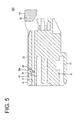
- the (both) restricting portion(s) 69 particularly are arranged to substantially face the (both) escaping portion(s) 28 e.g. from below as shown in FIG. 5 .
- the housing 10 is connected to the mating housing 90 along the connecting direction CD.
- the lock projection 93 of the mating housing 90 interferes with the lock portion 22 to deflect and deform the lock arm 15, whereby the arm main body 17 is inclined and the detecting member 60 assembled with the arm main body 17 is also inclined.
- the (both) restricting portion(s) 69 at least partly is/are inserted into the (both) escaping portion(s) 28 (e.g. from below) to avoid the interference of the (both) restricting portion(s) 69 and the (both) side wall(s) 25.
- the stopper wall 26 of the housing 10 particularly is located at a forward projecting position of the resilient locking portion 64 of the detecting member 60 in the inclined state.
- the lock projection 93 at least partly is fitted into the lock hole 21 to push up or displace the locking projection 71, thereby releasing a locked state of the locking projection 71 and the lock portion 22. In this way, a movement of the detecting member 60 towards or to the detection position DP is allowed.
- the detecting member 60 is displaced (e.g. pushed) toward the detection position DP.
- the locking projection 71 slides on the upper surface(s) of the lock projection 93 and the lock portion 22, whereby the resilient locking portion 64 is kept deflected and deformed.
- the upper plate portion 61 of the detecting member 60 is also pushed up or displaced by the resilient locking portion 64 to be resiliently deflected and deformed (see FIG. 3 ).
- the (particularly both) restricting portion(s) 69 come(s) into contact with the front wall(s) of the (particularly both) escaping portion(s) 28, thereby preventing the detecting member 60 from being displaced (pushed) to the detection position DP while being kept in the inclined state.
- the front end(s) of the (both) restricting portion(s) 69 slide(s) on guiding inclined surface(s) 28a formed on (particularly substantially the lower end(s) of the front wall(s) of) the (both) escaping portion(s) 28 to be guided downwardly, whereby the inclined state of the detecting member 60 is gradually canceled.
- the detecting member 60 substantially is returned to a horizontal posture extending along the front-back direction (connecting direction CD).
- the (both) restricting portion(s) 69 at least partly is/are inserted into the (both) guide portion(s) 27. Thereafter, the (both) restricting portion(s) 69 slide(s) on the (both) guide portion(s) 27 and move(s) forward, whereby the detecting member 60 is guided to the detection position DP.
- the locking projection 71 moves over the upper surface of the lock portion 22 and the resilient locking portion 64 is resiliently displaced in the return direction. In this way, the locking projection 71 is arranged to be lockable to the front end of the lock portion 22 and a movement of the detecting member 60 toward the standby position SB in the return direction particularly is prevented.
- the detecting member 60 cannot be moved from the standby position SP to the detection position DP. Therefore, if the detecting member 60 is immovable, it can be judged that the two housings 10, 90 are in the semi-connected state.
- the restricting portion(s) 69 come(s) into contact with the front wall(s) of the escaping portion(s) 28 if the detecting member 60 is in the inclined state when being pushed to the detection position DP. This prevents the detecting member 60 from reaching the detection position DP while being kept in the inclined state. Further, the detecting member 60 can reach the detection position DP in a state corrected substantially to the horizontal posture, which is a proper posture, by being guided by the guiding inclined surface(s) 28a of the escaping portion(s) 28.
- the front end of the detecting member 60 interferes with the stopper wall 26 located at an intermediate position of a virtual movement path of the detecting member 60 when the detecting member 60 in the inclined state is directly pushed forward, and the detecting member 60 does not reach the detection position DP, thereby avoiding a situation where the detecting member 60 is not held at the detection position DP and comes out of the housing 10 and other unfavorable situations.
- the restricting portion(s) 69 at least partly is/are inserted into the guide portion(s) 27, thereby ensuring stability in movement when the detecting member 60 reaches the detection position DP from the standby position SP.
- a detecting member 60 is supported on a lock arm 15 of the housing 10 movably between a standby position SP and a detection position DP.
- the detecting member 60 includes one or more restricting portions 69 and the housing 10 includes one or more escaping portions 28.
- the one or more escaping portions 28 extend in a direction intersecting with a connecting direction CD, and the one or more restricting portions 69 at least partly are inserted thereinto when the detecting member 60 is inclined in a connecting process and brought into contact with a wall surface facing in a moving direction of the detecting member 60 to prevent the detecting member 60 from reaching the detection position DP while substantially being kept in an inclined state when the detecting member 60 moves from the standby position SP toward the detection position DP.
Landscapes
- Details Of Connecting Devices For Male And Female Coupling (AREA)
Abstract
Description
- The present invention relates to a connector and to a method of connecting it.
- A connector described in Japanese Unexamined Patent Publication No.
2009-158263 - After the two housings are properly connected, the detecting member may remain inclined when the detecting member moves toward the detection position. Then, there is a possibility that the detecting member kept in the inclined state interferes with a facing wall of the housing or the like and comes off, which may impair reliability in connection detection by the detecting member.
- The present invention was completed based on the above situation and aims to enhance reliability in connection detection.
- This object is solved according to the invention by the features of the independent claims. Particular embodiments of the invention are subject of the dependent claims.
- According to one aspect, there is provided a connector, including a housing including at least one deflectable lock arm and connectable to a mating housing; and at least one detecting member movable substantially in a connecting direction from a standby position to a detection position in a state supported on the lock arm, wherein the lock arm is deflected and deformed and the detecting member is kept at the standby position in a state inclined with respect to the connecting direction in the process of connecting the housing to the mating housing; the lock arm is displaced in a return direction to hold the mating housing in a connected state and the detecting member is allowed to move to the detection position as the housing is properly connected to the mating housing; the detecting member includes a restricting portion; and the housing includes at least one escaping portion substantially extending in a direction intersecting with the connecting direction, configured such that the restricting portion is inserted thereinto when the detecting member is inclined in a connecting process and configured to prevent the detecting member from reaching the detection position while being kept in an inclined state by causing the restricting portion to come into contact with a wall surface substantially facing in a moving direction of the detecting member when the detecting member moves from the standby position to the detection position.
- According to a particular embodiment, the housing includes at least one guide portion connected to the at least one escaping portion, substantially extending in the connecting direction and configured such that the restricting portion is inserted thereinto to guide a movement of the detecting member in the process of moving the detecting member from the standby position to the detection position. The detecting member can smoothly reach the detection position from the standby position by the at least partial insertion of the restricting portion into the guide portion.
- Particularly, an opening edge of the guide portion and/or of the escaping portion is curved and chamfered substantially over the entirety.
- Further particularly, at least one wall of the housing is present at an intermediate position of a virtual movement path when the detecting member in the inclined state in the connecting process is assumed to move to the detection position while being kept in the inclined state. In the prior art, the detecting member in the inclined state may not reach the detection position by coming into contact with the wall of the housing on the way to the detection position. However, in the case of this configuration, a movement of the detecting member in the inclined state to the detection position is hindered by the escaping portion, wherefore the inclined state of the detecting member is canceled and the detecting member is reliably brought to the detection position.
- Further particularly, the escaping portion has at least one guiding inclined surface, which is configured to cancel the inclined state of the detecting member and guide the detecting member to be in a proper posture by causing the detecting member moving toward the detection position to slide thereon, on the wall surface substantially facing in the moving direction of the detecting member to the detection position. This enables the detecting member to reach the detection position while being corrected to the proper posture.
- Further particularly, the detecting member includes an upper plate portion, a pair of side plate portions substantially extending in the connecting direction substantially along the
upper plate portion 61, arear portion 63 substantially extending in the width direction and/or a resilient locking portion substantially extending forward from the rear portion. - Further particularly, a front end of the upper plate portion is arranged to be retracted more backward with respect to the front ends of the both side plate portions and/or the front end of the resilient locking portion.
- Further particularly, a front end of the restricting portion is inclined backward toward a projecting tip and/or a rear end of the restricting portion is arranged substantially along the width direction.
- Further particularly, when the detecting member is at the standby position, the retaining receiving portion is arranged to be able to come into contact with the retaining portion to prevent a backward movement of the detecting member and/or the locking projection is arranged to be able to come into contact with a rear end of a lock portion of the housing to prevent a forward movement of the detecting member.
- Further particularly, when the detecting member is at the detection position, the locking projection is arranged to be able to come into contact with the lock portion to prevent a backward movement of the detecting member and/or the upper plate portion is arranged to be able to come into contact with a stopper wall of the housing to prevent a forward movement of the detecting member
- Further particularly, at least one confirmation window is provided in the detection member and/or the housing so as to allow confirming the position of the detecting member through the confirmation window.
- According to a further aspect of the invention, there is provided a method of connecting a connector, in particular according to the above aspect or a particular embodiment thereof, to a mating connector, comprising the following steps: providing a connector comprising a housing including at least one deflectable lock arm and connectable to a mating housing of the mating connector; movably mounting at least one detecting member to the housing so as to be movable substantially in a connecting direction from a standby position to a detection position in a state supported on the lock arm; and connecting the housing to the mating housing; wherein in the process of connecting the housing to the mating housing the lock arm is deflected and deformed and the detecting member is kept at the standby position in a state inclined with respect to the connecting direction; wherein as the housing is properly connected to the mating housing the lock arm is displaced in a return direction to hold the mating housing in a connected state and the detecting member is allowed to move to the detection position; and wherein a restricting portion of the detecting member is inserted into at least one escaping portion substantially extending in a direction intersecting with the connecting direction when the detecting member is inclined in a connecting process and configured to prevent the detecting member from reaching the detection position while being kept in an inclined state by causing the restricting portion to come into contact with a wall surface substantially facing in a moving direction of the detecting member when the detecting member moves from the standby position to the detection position.
- According to a particular embodiment, the restricting portion is inserted into at least one guide portion of the housing connected to the at least one escaping portion, substantially extending in the connecting direction, in order to guide a movement of the detecting member in the process of moving the detecting member from the standby position to the detection position.
- Particularly, at least one wall of the housing is present at an intermediate position of a virtual movement path when the detecting member in the inclined state in the connecting process is assumed to move to the detection position while being kept in the inclined state.
- Further particularly, the escaping portion has the inclined state of the detecting member is canceled by at least one guiding inclined surface of the escaping portion and the detecting member is guided by the guiding inclined surface to be in a proper posture by causing the detecting member moving toward the detection position to slide thereon, wherein the guiding inclined surface is provided on the wall surface substantially facing in the moving direction of the detecting member to the detection position.
- According to the above, if the detecting member is kept inclined with respect to the connecting direction when the detecting member moves toward the detection position after the two housings are properly connected, the restricting portion comes into contact with the wall surface of the escaping portion. Thus, a movement of the detecting member kept in the inclined state to the detection position is prevented. Therefore, reliability in connection detection by the detecting member can be enhanced.
- These and other objects, features and advantages of the present invention will become more apparent upon reading of the following detailed description of preferred embodiments and accompanying drawings. It should be understood that even though embodiments are separately described, single features thereof may be combined to additional embodiments.
-
FIG. 1 is a plan view showing a state where a detecting member is held at a standby position in a housing in a connector of an embodiment of the present invention, -
FIG. 2 is a section showing a state where the housing is lightly fitted to a mating housing, -
FIG. 3 is a section showing a state where the housing is properly connected to the mating housing and the detecting member at the standby position is released from a locked state, -
FIG. 4 is a section showing a state reached by moving the detecting member to a detection position, -
FIG. 5 is a section, cut at a position corresponding to restricting portions, showing a state where the detecting member is held at the standby position in the housing, -
FIG. 6 is an enlarged view of an essential part ofFIG. 5 , -
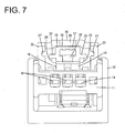
FIG. 7 is a rear view of the housing, -
FIG. 8 is a plan view of the housing, -
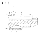
FIG. 9 is a section of the housing, and -
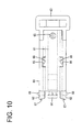
FIG. 10 is a plan view of the detecting member. - A particular embodiment of the present invention is described based on the drawings. A connector of this embodiment includes a
housing 10 and at least one detectingmember 60 to be assembled with thehousing 10. Thehousing 10 is connectable to amating housing 90. Note that, in the following description, sides substantially facing each other when the connection of the twohousings FIGS. 2 to 7 and9 . In the following description, the front-back direction is synonymous with a connecting direction CD. - The
mating housing 90 is made e.g. of synthetic resin and includes, as shown inFIG. 2 , a (particularly substantially block-like)terminal accommodating portion 91 and atubular receptacle 92 substantially projecting forward from (particularly the front end of) theterminal accommodating portion 91. Alock projection 93 is provided on the lateral (upper) surface of the lateral (upper) wall of thereceptacle 92. - One or more, particularly a plurality of
mating cavities 94 are provided to substantially extend in the front-back direction in theterminal accommodating portion 91. Therespective mating cavities 94 particularly are arranged substantially side by side in a width direction and one or moremating terminal fittings 80 at least partly are inserted thereinto from an insertion side, particularly substantially from behind, as shown inFIG. 4 . Themating terminal fitting 80 is made of electrically conductive material such as metal and includes amale tab 81 substantially projecting forward and a mating wire connection portion (particularly comprising at least one barrel-shaped mating crimping portion 82) located behind themale tab 81. The mating wire connection portion is to be connected to a wire W2, particularly themating crimping portion 82 is connected by crimping to an end part of the wire W2. Further, themale tab 81 is arranged to at least partly project into thereceptacle 92. - The
housing 10 is made e.g. of synthetic resin and includes, as shown inFIG. 9 , a (particularly substantially block-like) housingmain body 11 and a tubularfitting tube portion 12 at least partly surrounding the housingmain body 11. A space between the housingmain body 11 and thefitting tube portion 12 substantially is open forward as aconnection space 13. As shown inFIG. 2 , thereceptacle 92 of themating housing 90 at least partly is fittable into theconnection space 13 of thehousing 10. - One or more, particularly a plurality of
cavities 14 are provided to extend in the front-back direction at one or more positions corresponding to the one or morerespective mating cavities 94 in the housingmain body 11. Therespective cavities 14 particularly are arranged substantially side by side in the width direction as shown inFIG. 7 and one or moreterminal fittings 50 are to be at least partly inserted thereinto from an insertion side, particularly substantially from behind, as shown inFIG. 4 . Theterminal fitting 50 is made of electrically conductive material such as metal and includes, as shown inFIG. 4 , a tubular terminalmain body 51 and a wire connection portion (particularly comprising at least one barrel-shaped crimping portion 52) located behind the terminalmain body 51. The wire connection portion is to be electrically connected to a wire W1, particularly the crimpingportion 52 is connected by crimping to an end part of the wire W1. Further, themale tab 81 of the mating terminal fitting 80 is to be at least partly inserted into the terminalmain body 51 when the twohousings male tab 81 at least partly is inserted into the terminalmain body 51 and comes into contact with an unillustrated contact portion in the terminalmain body 51, whereby the twoterminal fittings - At least one
lock arm 15 is provided on the lateral surface (particularly the upper surface) of the housingmain body 11. Thelock arm 15 includes one or more, particularly a pair ofleg portions 16 standing or projecting from (particularly the upper surface of) the housingmain body 11 as shown inFIG. 7 and an armmain body 17 substantially extending in both forward and backward directions from (particularly the upper or distal ends of) the (particularly both) leg portion(s) 16 as shown inFIG. 2 . The armmain body 17 is capable of a seesaw-like pivotal displacement (resiliently displaceable) with the (both) leg portion(s) 16 as a supporting point. - As shown in
FIGS. 2 and8 , the armmain body 17 includes an inserting tube portion 18 (particularly substantially in the form of a rectangular or polygonal tube) penetrating in the front-back direction. The detectingmember 60 is to be mounted into the insertingtube portion 18 from a mounting side, particularly substantially from behind. As shown inFIG. 8 , a front part (particularly a substantially front half) of the upper wall of the insertingtube portion 18 is open as a cut-like opening 19. Further, alock hole 21 is provided to penetrate through the lower wall of the insertingtube portion 18 below theopening 19. In a state where the detectingmember 60 is not assembled with thelock arm 15, the lateral (upper) surface of the housingmain body 11 can be visually confirmed through theopening 19 and thelock hole 21. Alock portion 22 is provided to substantially extend in the width direction before thelock hole 21 on a front end part of the insertingtube portion 18. - Further, as shown in
FIGS. 7 and8 , one or more, particularly a pair ofrail portions 23 are provided to substantially extend in the front-back direction on at least one side of the insertingtube portion 18, particularly on substantially opposite side edges of the insertingtube portion 18. Furthermore, one or more, particularly a pair of retainingportions 24 integrally or unitarily coupled to the rail portion(s) 23 (particularly to lower sides of the both rail portions 23) are provided to project substantially in an intermediate position of the insertingtube portion 18 in the front-back direction (particularly substantially in the center(s) of the (opposite) side edge(s) of the insertingtube portion 18 in the front-back direction). - As shown in
FIG. 7 , one or more, particularly a pair ofside walls 25 are provided to stand substantially vertically at or project from (particularly substantially opposite sides of) thelock arm 15 atop thefitting tube portion 12. Thelock arm 15 substantially is protected by being at least partly laterally covered by the (particularly both) side wall(s) 25. Further specifically, at least one stopper wall 26 (seeFIG. 8 ) bridging between (particularly the upper edges of the front ends of) the bothside walls 25 are provided to be higher above thefitting tube portion 12. - As shown in
FIGS. 7 and9 , one or more, particularly a pair ofguide portions 27 substantially in the form of recessed grooves and/or extending over the entire length in the front-back direction are provided on the inner surface(s) of the (both) side wall(s) 25 (particularly substantially on surfaces of the bothside walls 25 facing each other). One or more (later-described) restrictingportions 69 of the detectingmember 60 at least partly are to be fitted and inserted into the (both) guide portion(s) 27. Further, as shown inFIGS. 6 and9 , one or more, particularly a pair of escapingportions 28 particularly substantially in the form of recessed grooves, communicating with intermediate part(s) of the guide portion(s) 27 in the front-back direction (specifically, front end part(s) in the front-back direction), extending from coupled position(s) in an upward or outward direction intersecting with the front-back direction (connection direction CD) and/or open on the upper or distal end(s) of the side wall(s) 25 is/are provided on the inner surface(s) of the (both) side wall(s) 25. The restricting portion(s) 69 moving from the (both) guide portion(s) 27 is/are loosely insertable into the (both) escapingportions 28. Note that opening edge(s) of the guide portion(s) 27 and the escaping portion(s) 28 on the inner surface(s) of the (both) side wall(s) 25 particularly are curved and chamfered substantially over the entireties. - Next, the detecting
member 60 is described. The detectingmember 60 is made e.g. of synthetic resin and particularly substantially has a rectangular or polygonal shape long in the front-back direction in a plan view as shown inFIG. 10 . The detectingmember 60 is movable to a standby position SP (seeFIGS. 1 to 3 and5 ) and a detection position DP (seeFIG. 4 ) before the standby position SP in a state supported on thelock arm 15. - Specifically, as shown in
FIGS. 2 and10 , the detectingmember 60 includes an upper orouter plate portion 61 particularly substantially in the form of a rectangular plate, a pair ofside plate portions 62 projecting at an angle different from 0° or 180°, preferably substantially perpendicularly (e.g. downwardly) from (particularly substantially opposite side edges of) theupper plate portion 61 and/or substantially extending in the front-back direction substantially along (particularly the opposite side edges of) theupper plate portion 61, arear portion 63 integrally or unitarily coupled to (particularly the rear ends of) the bothside plate portions 62 and theupper plate portion 61 and substantially extending in the width direction and/or a long and narrowresilient locking portion 64 substantially extending forward from therear portion 63, particularly from a widthwise central part of a lower part of the front surface of therear portion 63. - As shown in
FIGS. 2 and10 , therear portion 63 particularly bulges further toward opposite widthwise sides and upper side than theupper plate portion 61 and the detectingmember 60 can be moved by gripping therear portion 63. Theupper plate portion 61 particularly substantially is in the form of a flat plate and a (particularly substantially circular)confirmation window 65 is open on a rear end part as shown inFIG. 10 . Further, one or more, particularly a pair of mold removal holes 66 are open in the width direction in the upper plate portion 61 (particularly in a substantially central part of theupper plate portion 61 in the front-back direction) by the passage of a mold when retaining receiving portion(s) 68 to be described later is/are molded. Note that the front end of theupper plate portion 61 particularly is arranged to be retracted more backward with respect to the front ends of the bothside plate portions 62 and/or the front end of theresilient locking portion 64. - As shown in
FIG. 10 , one or more, particularly a pair ofrail receiving portions 67 particularly substantially in the form of recessed grooves, extending in the front-back direction and/or open on the front ends are provided on the inner surface(s) of the (both) side plate portion(s) 62. Further, one or more, particularly a pair of retaining receivingportions 68 are provided to project below the (both) rail receiving portion(s) 67 in the (both) side plate portion(s) 62, particularly in substantially central parts of the inner surfaces of the bothside plate portions 62 in the front-back direction. - As shown in
FIG. 10 , one or more, particularly a pair of restrictingportions 69 are provided to project on (particularly front end parts of outer side edges of) the (both) side plate portion(s) 62. The (particularly both) restricting portion(s) 69 particularly is/are arranged before the front end of theupper plate portion 61. The front end of the restrictingportion 69 particularly is inclined backward toward a projecting tip and the rear end thereof is arranged along the width direction. As shown inFIG. 6 , a vertical dimension of the restrictingportion 69 particularly is slightly smaller than a vertical, groove width of theguide portion 27 and/or a dimension thereof in the front-back direction particularly is sufficiently smaller than a groove width of the escapingportion 28 in the front-back direction. - As shown in
FIGS. 3 and4 , theresilient locking portion 64 is deflectable and deformable substantially in the vertical direction or inwardly/outwardly or radially towards and away from the housingmain body 11. In this case, theresilient locking portion 64 resiliently displaced upwardly or outwardly comes into contact with the lateral (upper)plate portion 61, thereby preventing excessive deformation of theresilient locking portion 64. Further, a claw-like locking projection 71 is provided to project downwardly or inwardly on or near the front end of theresilient locking portion 64. - When the detecting
member 60 is assembled with thelock arm 15, the upper orouter plate portion 61 is arranged to at least partly cover the armmain body 17 from above or outside, theresilient locking portion 64 at least partly is inserted into the insertingtube portion 18 of the armmain body 17, the (particularly both) side plate portion(s) 62 is/are arranged adjacent to the inserting tube portion 18 (particularly at substantially opposite lateral sides of the inserting tube portion 18) and the (particularly both) rail portion(s) 23 at least partly is/are fitted and inserted into the (both) rail receiving portion(s) 67 as shown inFIGS. 1 and2 . - As shown in
FIG. 2 , the lateral (e.g. upper) wall of the insertingtube portion 18 at least partly is sandwiched between theupper plate portion 61 and theresilient locking portion 64 of the detectingmember 60. When the detectingmember 60 is at the standby position SP, the (both) retaining receiving portion(s) 68 particularly is/are arranged to be able to come into contact with the front end(s) of the (both) retaining portion(s) 24 to prevent a backward movement of the detectingmember 60 and/or the lockingprojection 71 particularly is arranged to be able to come into contact with the rear end of thelock portion 22 to prevent a forward movement of the detectingmember 60, with the result that the detectingmember 60 is held or positioned at the standby position SP. - Further, as shown in
FIG. 4 , when the detectingmember 60 is at the detection position DP, the lockingprojection 71 particularly is arranged to be able to come into contact with the front end of thelock portion 22 to prevent a backward movement of the detectingmember 60 and/or the front end of theupper plate portion 61 particularly is arranged to be able to come into contact with the rear end of thestopper wall 26 to prevent a forward movement of the detectingmember 60, with the result that the detectingmember 60 is held or positioned at the detection position DP. The armmain body 17 particularly cannot be visually confirmed through theconfirmation window 65 as shown inFIG. 2 when the detectingmember 60 is at the standby position SP, but particularly can be visually confirmed through theconfirmation window 65 as shown inFIG. 4 when the detectingmember 60 is at the detection position DP. Thus, the position of the detectingmember 60 can be confirmed through theconfirmation window 65. - Next, functions of the connector of this embodiment are described.
- In assembling the detecting
member 60 with thelock arm 15, theresilient locking portion 64 at least partly is inserted into the inserting tube portion 18 (particularly substantially from behind), the (particularly both) rail portion(s) 23 at least partly is/are inserted into the (particularly both) rail receiving portion(s) 67 and the (particularly both) restricting portion(s) 69 at least partly is/are inserted into the (both) guide portion(s) 27. In that state, the detectingmember 60 is slid or displaced forward to the standby position SP (seeFIGS. 1 to 3 ). At the standby position SP, the (both) restricting portion(s) 69 particularly are arranged to substantially face the (both) escaping portion(s) 28 e.g. from below as shown inFIG. 5 . - Subsequently, the
housing 10 is connected to themating housing 90 along the connecting direction CD. In the process of connecting the twohousings lock projection 93 of themating housing 90 interferes with thelock portion 22 to deflect and deform thelock arm 15, whereby the armmain body 17 is inclined and the detectingmember 60 assembled with the armmain body 17 is also inclined. When the detectingmember 60 is inclined, the (both) restricting portion(s) 69 at least partly is/are inserted into the (both) escaping portion(s) 28 (e.g. from below) to avoid the interference of the (both) restricting portion(s) 69 and the (both) side wall(s) 25. Further, thestopper wall 26 of thehousing 10 particularly is located at a forward projecting position of theresilient locking portion 64 of the detectingmember 60 in the inclined state. - Thereafter, when the two
housings FIG. 3 , thelock portion 22 moves over thelock projection 93, thelock arm 15 at least partly is resiliently displaced in the return direction and thelock portion 22 is arranged to be lockable to the rear end of thelock projection 93. In this way, the twohousings housings terminal fitting 50 is electrically connected to the corresponding mating terminal fitting 80 (seeFIG. 4 ). - Further, when the two
housings FIG. 3 , thelock projection 93 at least partly is fitted into thelock hole 21 to push up or displace the lockingprojection 71, thereby releasing a locked state of the lockingprojection 71 and thelock portion 22. In this way, a movement of the detectingmember 60 towards or to the detection position DP is allowed. - Subsequently, the detecting
member 60 is displaced (e.g. pushed) toward the detection position DP. In the process of moving the detectingmember 60 toward the detection position DP, the lockingprojection 71 slides on the upper surface(s) of thelock projection 93 and thelock portion 22, whereby theresilient locking portion 64 is kept deflected and deformed. At this time, theupper plate portion 61 of the detectingmember 60 is also pushed up or displaced by theresilient locking portion 64 to be resiliently deflected and deformed (seeFIG. 3 ). If the detectingmember 60 is kept entirely inclined except at theresilient locking portion 64 when moving toward the detection position DP, the (particularly both) restricting portion(s) 69 come(s) into contact with the front wall(s) of the (particularly both) escaping portion(s) 28, thereby preventing the detectingmember 60 from being displaced (pushed) to the detection position DP while being kept in the inclined state. Further, if it is attempted to displace (push) the detectingmember 60 kept in the entirely inclined state to the detection position DP, the front end(s) of the (both) restricting portion(s) 69 slide(s) on guiding inclined surface(s) 28a formed on (particularly substantially the lower end(s) of the front wall(s) of) the (both) escaping portion(s) 28 to be guided downwardly, whereby the inclined state of the detectingmember 60 is gradually canceled. In this way, the detectingmember 60 substantially is returned to a horizontal posture extending along the front-back direction (connecting direction CD). As the detectingmember 60 substantially returns to the horizontal posture, the (both) restricting portion(s) 69 at least partly is/are inserted into the (both) guide portion(s) 27. Thereafter, the (both) restricting portion(s) 69 slide(s) on the (both) guide portion(s) 27 and move(s) forward, whereby the detectingmember 60 is guided to the detection position DP. - When the detecting
member 60 substantially reaches the detection position DP as shown inFIG. 4 , the lockingprojection 71 moves over the upper surface of thelock portion 22 and theresilient locking portion 64 is resiliently displaced in the return direction. In this way, the lockingprojection 71 is arranged to be lockable to the front end of thelock portion 22 and a movement of the detectingmember 60 toward the standby position SB in the return direction particularly is prevented. - On the other hand, if the two
housings projection 71 is not pushed up by thelock projection 93 and the locked state of the lockingprojection 71 and thelock portion 22 is maintained. Thus, the detectingmember 60 cannot be moved from the standby position SP to the detection position DP. Therefore, if the detectingmember 60 is immovable, it can be judged that the twohousings - As described above, according to this embodiment, the restricting portion(s) 69 come(s) into contact with the front wall(s) of the escaping portion(s) 28 if the detecting
member 60 is in the inclined state when being pushed to the detection position DP. This prevents the detectingmember 60 from reaching the detection position DP while being kept in the inclined state. Further, the detectingmember 60 can reach the detection position DP in a state corrected substantially to the horizontal posture, which is a proper posture, by being guided by the guiding inclined surface(s) 28a of the escaping portion(s) 28. Thus, the front end of the detectingmember 60 interferes with thestopper wall 26 located at an intermediate position of a virtual movement path of the detectingmember 60 when the detectingmember 60 in the inclined state is directly pushed forward, and the detectingmember 60 does not reach the detection position DP, thereby avoiding a situation where the detectingmember 60 is not held at the detection position DP and comes out of thehousing 10 and other unfavorable situations. - Further, in the process of moving the detecting
member 60 toward or to the detection position DP, the restricting portion(s) 69 at least partly is/are inserted into the guide portion(s) 27, thereby ensuring stability in movement when the detectingmember 60 reaches the detection position DP from the standby position SP. - Accordingly, to enhance reliability in connection detection, a detecting
member 60 is supported on alock arm 15 of thehousing 10 movably between a standby position SP and a detection position DP. The detectingmember 60 includes one or more restrictingportions 69 and thehousing 10 includes one or more escapingportions 28. The one or more escapingportions 28 extend in a direction intersecting with a connecting direction CD, and the one or more restrictingportions 69 at least partly are inserted thereinto when the detectingmember 60 is inclined in a connecting process and brought into contact with a wall surface facing in a moving direction of the detectingmember 60 to prevent the detectingmember 60 from reaching the detection position DP while substantially being kept in an inclined state when the detectingmember 60 moves from the standby position SP toward the detection position DP. - The present invention is not limited to the above described and illustrated embodiment. For example, the following modes are also included in the technical scope of the present invention.
- (1) The front ends of the escaping portions may arcuately extend toward front end sides of the guide portions.
- (2) The guide portions that function to guide the movement of the detecting member can be omitted.
- (3) The locking projection of the resilient locking portion may be arranged to be lockable to a recess of the mating housing, thereby preventing a return movement of the detecting member to the standby position.
- (4) The numbers of the restricting portions and the escaping portions are arbitrary. For example, one restricting portion and one escaping portion may be respectively provided on the detecting member and the housing.
-
- 10
- housing
- 15
- lock arm
- 26
- stopper wall (wall)
- 27
- guide portion
- 28
- escaping portion
- 28a
- guiding inclined surface
- 60
- detecting member
- 69
- restricting portion
- 90
- mating housing
Claims (15)
- A connector, comprising:a housing (10) including at least one deflectable lock arm (15) and connectable to a mating housing (90); andat least one detecting member (60) movable substantially in a connecting direction (CD) from a standby position (SP) to a detection position (DP) in a state supported on the lock arm (15),wherein:the lock arm (15) is deflected and deformed and the detecting member (60) is kept at the standby position (SP) in a state inclined with respect to the connecting direction (CD) in the process of connecting the housing (10) to the mating housing (90);the lock arm (15) is displaced in a return direction to hold the mating housing (90) in a connected state and the detecting member (60) is allowed to move to the detection position (DP) as the housing (10) is properly connected to the mating housing (90);the detecting member (60) includes at least one restricting portion (69); andthe housing (10) includes at least one escaping portion (28) substantially extending in a direction intersecting with the connecting direction (CD), configured such that the restricting portion (69) is inserted thereinto when the detecting member (60) is inclined in a connecting process and configured to prevent the detecting member (60) from reaching the detection position (DP) while being kept in an inclined state by causing the restricting portion (69) to come into contact with a wall surface substantially facing in a moving direction of the detecting member (60) when the detecting member (60) moves from the standby position (SP) to the detection position (DP).
- A connector according to claim 1, wherein the housing (10) includes at least one guide portion (27) connected to the at least one escaping portion (28), substantially extending in the connecting direction (CD) and configured such that the restricting portion (69) is inserted thereinto to guide a movement of the detecting member (60) in the process of moving the detecting member (60) from the standby position (SP) to the detection position (DP).
- A connector according to claim 2, wherein an opening edge of the guide portion (27) and/or of the escaping portion (28) is curved and chamfered substantially over the entirety.
- A connector according to any one of the preceding claims, wherein at least one wall (26) of the housing (10) is present at an intermediate position of a virtual movement path when the detecting member (60) in the inclined state in the connecting process is assumed to move to the detection position (DP) while being kept in the inclined state.
- A connector according to any one of the preceding claims, wherein the escaping portion (28) has at least one guiding inclined surface (28a), which is configured to cancel the inclined state of the detecting member (60) and guide the detecting member (60) to be in a proper posture by causing the detecting member (60) moving toward the detection position (DP) to slide thereon, on the wall surface substantially facing in the moving direction of the detecting member (60) to the detection position (DP).
- A connector according to any one of the preceding claims, wherein the detecting member (60) includes an upper plate portion (61), a pair of side plate portions (62) substantially extending in the connecting direction (CD) substantially along the upper plate portion 61, a rear portion 63 substantially extending in the width direction and/or a resilient locking portion (64) substantially extending forward from the rear portion (63).
- A connector according to claim 6, wherein a front end of the upper plate portion (61) is arranged to be retracted more backward with respect to the front ends of the both side plate portions (62) and/or the front end of the resilient locking portion (64).
- A connector according to any one of the preceding claims, wherein a front end of the restricting portion (69) is inclined backward toward a projecting tip and/or a rear end of the restricting portion (69) is arranged substantially along the width direction.
- A connector according to any one of the preceding claims, wherein, when the detecting member (60) is at the standby position (SP), the retaining receiving portion (68) is arranged to be able to come into contact with the retaining portion (24) to prevent a backward movement of the detecting member (60) and/or the locking projection (71) is arranged to be able to come into contact with a rear end of a lock portion (22) of the housing (10) to prevent a forward movement of the detecting member (60).
- A connector according to claim 9, wherein, when the detecting member (60) is at the detection position (DP), the locking projection (71) is arranged to be able to come into contact with the lock portion (22) to prevent a backward movement of the detecting member (60) and/or the upper plate portion (61) is arranged to be able to come into contact with a stopper wall (26) of the housing (10) to prevent a forward movement of the detecting member (60)
- A connector according to any one of the preceding claims, wherein, at least one confirmation window (65) is provided in the detection member (60) and/or the housing (10) so as to allow confirming the position of the detecting member (60) through the confirmation window (65).
- A method of connecting a connector to a mating connector, comprising the following steps:providing a connector comprising a housing (10) including at least one deflectable lock arm (15) and connectable to a mating housing (90) of the mating connector;movably mounting at least one detecting member (60) to the housing (10) so as to be movable substantially in a connecting direction (CD) from a standby position (SP) to a detection position (DP) in a state supported on the lock arm (15); andconnecting the housing (10) to the mating housing (90);wherein in the process of connecting the housing (10) to the mating housing (90) the lock arm (15) is deflected and deformed and the detecting member (60) is kept at the standby position (SP) in a state inclined with respect to the connecting direction (CD);wherein as the housing (10) is properly connected to the mating housing (90) the lock arm (15) is displaced in a return direction to hold the mating housing (90) in a connected state and the detecting member (60) is allowed to move to the detection position (DP); andwherein a restricting portion (69) of the detecting member (60) is inserted into at least one escaping portion (28) substantially extending in a direction intersecting with the connecting direction (CD) when the detecting member (60) is inclined in a connecting process and configured to prevent the detecting member (60) from reaching the detection position (DP) while being kept in an inclined state by causing the restricting portion (69) to come into contact with a wall surface substantially facing in a moving direction of the detecting member (60) when the detecting member (60) moves from the standby position (SP) to the detection position (DP).
- A method according to claim 12, wherein the restricting portion (69) is inserted into at least one guide portion (27) of the housing (10) connected to the at least one escaping portion (28), substantially extending in the connecting direction (CD), in order to guide a movement of the detecting member (60) in the process of moving the detecting member (60) from the standby position (SP) to the detection position (DP).
- A method according to claim 12 or 13, wherein at least one wall (26) of the housing (10) is present at an intermediate position of a virtual movement path when the detecting member (60) in the inclined state in the connecting process is assumed to move to the detection position (DP) while being kept in the inclined state.
- A method according to any one of the preceding claims 12 to 14, wherein the escaping portion (28) has
the inclined state of the detecting member (60) is canceled by at least one guiding inclined surface (28a) of the escaping portion (28) and the detecting member (60) is guided by the guiding inclined surface (28a) to be in a proper posture by causing the detecting member (60) moving toward the detection position (DP) to slide thereon, wherein the guiding inclined surface (28a) is provided on the wall surface substantially facing in the moving direction of the detecting member (60) to the detection position (DP).
Applications Claiming Priority (1)
| Application Number | Priority Date | Filing Date | Title |
|---|---|---|---|
| JP2014037988A JP6150172B2 (en) | 2014-02-28 | 2014-02-28 | connector |
Publications (2)
| Publication Number | Publication Date |
|---|---|
| EP2913900A1 true EP2913900A1 (en) | 2015-09-02 |
| EP2913900B1 EP2913900B1 (en) | 2017-03-22 |
Family
ID=52596724
Family Applications (1)
| Application Number | Title | Priority Date | Filing Date |
|---|---|---|---|
| EP15000551.0A Not-in-force EP2913900B1 (en) | 2014-02-28 | 2015-02-26 | Connector and method of connecting it |
Country Status (4)
| Country | Link |
|---|---|
| US (1) | US9362652B2 (en) |
| EP (1) | EP2913900B1 (en) |
| JP (1) | JP6150172B2 (en) |
| CN (1) | CN104882735B (en) |
Families Citing this family (7)
| Publication number | Priority date | Publication date | Assignee | Title |
|---|---|---|---|---|
| JP6417370B2 (en) * | 2016-07-29 | 2018-11-07 | 矢崎総業株式会社 | connector |
| CN111448719B (en) * | 2017-12-26 | 2021-06-25 | 住友电装株式会社 | Connector |
| JP2020027720A (en) * | 2018-08-10 | 2020-02-20 | 住友電装株式会社 | connector |
| JP2020047365A (en) * | 2018-09-14 | 2020-03-26 | 住友電装株式会社 | connector |
| CN109103694A (en) * | 2018-09-19 | 2018-12-28 | 苏州欧康诺电子科技股份有限公司 | A kind of hard disk device for quick testing |
| JP7144480B2 (en) * | 2020-04-10 | 2022-09-29 | 住友電装株式会社 | Connector unit and wire harness |
| JP2023162642A (en) * | 2022-04-27 | 2023-11-09 | 住友電装株式会社 | lever type connector |
Citations (4)
| Publication number | Priority date | Publication date | Assignee | Title |
|---|---|---|---|---|
| US20020064997A1 (en) * | 2000-11-27 | 2002-05-30 | Sumitomo Wiring Systems, Ltd. | Connector |
| US20070178739A1 (en) * | 2006-01-27 | 2007-08-02 | Yazaki Corporation | Connector |
| US20090170362A1 (en) * | 2007-12-26 | 2009-07-02 | Sumitomo Wiring Systems, Ltd. | Connector and a connector assembly |
| US20110021060A1 (en) * | 2009-07-27 | 2011-01-27 | Kazumi Urano | Connector |
Family Cites Families (8)
| Publication number | Priority date | Publication date | Assignee | Title |
|---|---|---|---|---|
| US5120255A (en) * | 1990-03-01 | 1992-06-09 | Yazaki Corporation | Complete locking confirming device for confirming the complete locking of an electric connector |
| JP3553805B2 (en) * | 1998-08-03 | 2004-08-11 | 矢崎総業株式会社 | Connector mating structure |
| JP3800312B2 (en) * | 2000-10-31 | 2006-07-26 | 住友電装株式会社 | connector |
| JP4770346B2 (en) * | 2005-09-13 | 2011-09-14 | 住友電装株式会社 | connector |
| EP2249440B1 (en) * | 2007-08-01 | 2012-05-09 | Sumitomo Wiring Systems, Ltd. | A connector, connector assembly and connection method |
| JP5050820B2 (en) * | 2007-12-05 | 2012-10-17 | 住友電装株式会社 | connector |
| JP5341477B2 (en) * | 2008-11-04 | 2013-11-13 | 矢崎総業株式会社 | connector |
| JP5486859B2 (en) * | 2009-07-09 | 2014-05-07 | 矢崎総業株式会社 | connector |
-
2014
- 2014-02-28 JP JP2014037988A patent/JP6150172B2/en not_active Expired - Fee Related
-
2015
- 2015-02-09 US US14/616,979 patent/US9362652B2/en not_active Expired - Fee Related
- 2015-02-26 EP EP15000551.0A patent/EP2913900B1/en not_active Not-in-force
- 2015-02-28 CN CN201510090699.XA patent/CN104882735B/en not_active Expired - Fee Related
Patent Citations (5)
| Publication number | Priority date | Publication date | Assignee | Title |
|---|---|---|---|---|
| US20020064997A1 (en) * | 2000-11-27 | 2002-05-30 | Sumitomo Wiring Systems, Ltd. | Connector |
| US20070178739A1 (en) * | 2006-01-27 | 2007-08-02 | Yazaki Corporation | Connector |
| US20090170362A1 (en) * | 2007-12-26 | 2009-07-02 | Sumitomo Wiring Systems, Ltd. | Connector and a connector assembly |
| JP2009158263A (en) | 2007-12-26 | 2009-07-16 | Sumitomo Wiring Syst Ltd | Connector |
| US20110021060A1 (en) * | 2009-07-27 | 2011-01-27 | Kazumi Urano | Connector |
Also Published As
| Publication number | Publication date |
|---|---|
| CN104882735A (en) | 2015-09-02 |
| US9362652B2 (en) | 2016-06-07 |
| EP2913900B1 (en) | 2017-03-22 |
| JP6150172B2 (en) | 2017-06-21 |
| JP2015162416A (en) | 2015-09-07 |
| CN104882735B (en) | 2017-06-20 |
| US20150249300A1 (en) | 2015-09-03 |
Similar Documents
| Publication | Publication Date | Title |
|---|---|---|
| EP2913900B1 (en) | Connector and method of connecting it | |
| CN102810784B (en) | Connector and assembly method thereof | |
| KR101520585B1 (en) | Electrical connector with integrated moveable terminal stabilizer | |
| US7396253B2 (en) | Connector and a connector assembly | |
| US9570854B2 (en) | Terminal fitting with stabilizers and connector | |
| KR101329952B1 (en) | Electronic connector | |
| EP2416454B1 (en) | Connector | |
| KR101797249B1 (en) | Connector terminal position assurance device | |
| EP1962390B1 (en) | A connector and a connector assembly | |
| CN103368009B (en) | Connector | |
| EP2779317A1 (en) | Connector | |
| EP1701417A1 (en) | A joint connector and method of assembling it | |
| EP2637260A1 (en) | Connector, connector assembly and assembling method therefor | |
| EP2637261A1 (en) | Connector, connector assembly and assembling method therefor | |
| US10707616B2 (en) | Connector assembly with a lever and a lever lock for releasably locking the lever in a connection end position | |
| EP2479849A1 (en) | Connector | |
| US10826238B2 (en) | Connector and connector assembly | |
| US20140051276A1 (en) | Waterproof connector | |
| EP2315320A1 (en) | A shorting terminal, a connector and an assembling method therefor | |
| EP3324494B1 (en) | Connector | |
| KR20170070997A (en) | Locking structure of connector and connector | |
| US10566737B2 (en) | Connector and connector assembly | |
| JP5556568B2 (en) | connector | |
| JP2012109031A (en) | Connector | |
| US9899768B2 (en) | Connector with operating member to assist connection to mating connector and resilient piece to restrict inadvertent displacement of operating member |
Legal Events
| Date | Code | Title | Description |
|---|---|---|---|
| PUAI | Public reference made under article 153(3) epc to a published international application that has entered the european phase |
Free format text: ORIGINAL CODE: 0009012 |
|
| AK | Designated contracting states |
Kind code of ref document: A1 Designated state(s): AL AT BE BG CH CY CZ DE DK EE ES FI FR GB GR HR HU IE IS IT LI LT LU LV MC MK MT NL NO PL PT RO RS SE SI SK SM TR |
|
| AX | Request for extension of the european patent |
Extension state: BA ME |
|
| 17P | Request for examination filed |
Effective date: 20160226 |
|
| RBV | Designated contracting states (corrected) |
Designated state(s): AL AT BE BG CH CY CZ DE DK EE ES FI FR GB GR HR HU IE IS IT LI LT LU LV MC MK MT NL NO PL PT RO RS SE SI SK SM TR |
|
| GRAP | Despatch of communication of intention to grant a patent |
Free format text: ORIGINAL CODE: EPIDOSNIGR1 |
|
| RAP1 | Party data changed (applicant data changed or rights of an application transferred) |
Owner name: SUMITOMO WIRING SYSTEMS, LTD. |
|
| INTG | Intention to grant announced |
Effective date: 20160913 |
|
| GRAS | Grant fee paid |
Free format text: ORIGINAL CODE: EPIDOSNIGR3 |
|
| GRAJ | Information related to disapproval of communication of intention to grant by the applicant or resumption of examination proceedings by the epo deleted |
Free format text: ORIGINAL CODE: EPIDOSDIGR1 |
|
| GRAL | Information related to payment of fee for publishing/printing deleted |
Free format text: ORIGINAL CODE: EPIDOSDIGR3 |
|
| GRAR | Information related to intention to grant a patent recorded |
Free format text: ORIGINAL CODE: EPIDOSNIGR71 |
|
| INTC | Intention to grant announced (deleted) | ||
| GRAA | (expected) grant |
Free format text: ORIGINAL CODE: 0009210 |
|
| INTG | Intention to grant announced |
Effective date: 20170120 |
|
| AK | Designated contracting states |
Kind code of ref document: B1 Designated state(s): AL AT BE BG CH CY CZ DE DK EE ES FI FR GB GR HR HU IE IS IT LI LT LU LV MC MK MT NL NO PL PT RO RS SE SI SK SM TR |
|
| REG | Reference to a national code |
Ref country code: GB Ref legal event code: FG4D |
|
| REG | Reference to a national code |
Ref country code: CH Ref legal event code: EP |
|
| REG | Reference to a national code |
Ref country code: AT Ref legal event code: REF Ref document number: 878599 Country of ref document: AT Kind code of ref document: T Effective date: 20170415 |
|
| REG | Reference to a national code |
Ref country code: IE Ref legal event code: FG4D |
|
| REG | Reference to a national code |
Ref country code: DE Ref legal event code: R096 Ref document number: 602015001852 Country of ref document: DE |
|
| REG | Reference to a national code |
Ref country code: NL Ref legal event code: MP Effective date: 20170322 |
|
| PG25 | Lapsed in a contracting state [announced via postgrant information from national office to epo] |
Ref country code: GR Free format text: LAPSE BECAUSE OF FAILURE TO SUBMIT A TRANSLATION OF THE DESCRIPTION OR TO PAY THE FEE WITHIN THE PRESCRIBED TIME-LIMIT Effective date: 20170623 Ref country code: HR Free format text: LAPSE BECAUSE OF FAILURE TO SUBMIT A TRANSLATION OF THE DESCRIPTION OR TO PAY THE FEE WITHIN THE PRESCRIBED TIME-LIMIT Effective date: 20170322 Ref country code: NO Free format text: LAPSE BECAUSE OF FAILURE TO SUBMIT A TRANSLATION OF THE DESCRIPTION OR TO PAY THE FEE WITHIN THE PRESCRIBED TIME-LIMIT Effective date: 20170622 Ref country code: FI Free format text: LAPSE BECAUSE OF FAILURE TO SUBMIT A TRANSLATION OF THE DESCRIPTION OR TO PAY THE FEE WITHIN THE PRESCRIBED TIME-LIMIT Effective date: 20170322 Ref country code: LT Free format text: LAPSE BECAUSE OF FAILURE TO SUBMIT A TRANSLATION OF THE DESCRIPTION OR TO PAY THE FEE WITHIN THE PRESCRIBED TIME-LIMIT Effective date: 20170322 |
|
| REG | Reference to a national code |
Ref country code: LT Ref legal event code: MG4D |
|
| REG | Reference to a national code |
Ref country code: AT Ref legal event code: MK05 Ref document number: 878599 Country of ref document: AT Kind code of ref document: T Effective date: 20170322 |
|
| PG25 | Lapsed in a contracting state [announced via postgrant information from national office to epo] |
Ref country code: RS Free format text: LAPSE BECAUSE OF FAILURE TO SUBMIT A TRANSLATION OF THE DESCRIPTION OR TO PAY THE FEE WITHIN THE PRESCRIBED TIME-LIMIT Effective date: 20170322 Ref country code: LV Free format text: LAPSE BECAUSE OF FAILURE TO SUBMIT A TRANSLATION OF THE DESCRIPTION OR TO PAY THE FEE WITHIN THE PRESCRIBED TIME-LIMIT Effective date: 20170322 Ref country code: BG Free format text: LAPSE BECAUSE OF FAILURE TO SUBMIT A TRANSLATION OF THE DESCRIPTION OR TO PAY THE FEE WITHIN THE PRESCRIBED TIME-LIMIT Effective date: 20170622 Ref country code: SE Free format text: LAPSE BECAUSE OF FAILURE TO SUBMIT A TRANSLATION OF THE DESCRIPTION OR TO PAY THE FEE WITHIN THE PRESCRIBED TIME-LIMIT Effective date: 20170322 |
|
| PG25 | Lapsed in a contracting state [announced via postgrant information from national office to epo] |
Ref country code: NL Free format text: LAPSE BECAUSE OF FAILURE TO SUBMIT A TRANSLATION OF THE DESCRIPTION OR TO PAY THE FEE WITHIN THE PRESCRIBED TIME-LIMIT Effective date: 20170322 |
|
| PG25 | Lapsed in a contracting state [announced via postgrant information from national office to epo] |
Ref country code: AT Free format text: LAPSE BECAUSE OF FAILURE TO SUBMIT A TRANSLATION OF THE DESCRIPTION OR TO PAY THE FEE WITHIN THE PRESCRIBED TIME-LIMIT Effective date: 20170322 Ref country code: CZ Free format text: LAPSE BECAUSE OF FAILURE TO SUBMIT A TRANSLATION OF THE DESCRIPTION OR TO PAY THE FEE WITHIN THE PRESCRIBED TIME-LIMIT Effective date: 20170322 Ref country code: RO Free format text: LAPSE BECAUSE OF FAILURE TO SUBMIT A TRANSLATION OF THE DESCRIPTION OR TO PAY THE FEE WITHIN THE PRESCRIBED TIME-LIMIT Effective date: 20170322 Ref country code: SK Free format text: LAPSE BECAUSE OF FAILURE TO SUBMIT A TRANSLATION OF THE DESCRIPTION OR TO PAY THE FEE WITHIN THE PRESCRIBED TIME-LIMIT Effective date: 20170322 Ref country code: ES Free format text: LAPSE BECAUSE OF FAILURE TO SUBMIT A TRANSLATION OF THE DESCRIPTION OR TO PAY THE FEE WITHIN THE PRESCRIBED TIME-LIMIT Effective date: 20170322 Ref country code: EE Free format text: LAPSE BECAUSE OF FAILURE TO SUBMIT A TRANSLATION OF THE DESCRIPTION OR TO PAY THE FEE WITHIN THE PRESCRIBED TIME-LIMIT Effective date: 20170322 |
|
| PG25 | Lapsed in a contracting state [announced via postgrant information from national office to epo] |
Ref country code: PT Free format text: LAPSE BECAUSE OF FAILURE TO SUBMIT A TRANSLATION OF THE DESCRIPTION OR TO PAY THE FEE WITHIN THE PRESCRIBED TIME-LIMIT Effective date: 20170724 Ref country code: SM Free format text: LAPSE BECAUSE OF FAILURE TO SUBMIT A TRANSLATION OF THE DESCRIPTION OR TO PAY THE FEE WITHIN THE PRESCRIBED TIME-LIMIT Effective date: 20170322 Ref country code: IS Free format text: LAPSE BECAUSE OF FAILURE TO SUBMIT A TRANSLATION OF THE DESCRIPTION OR TO PAY THE FEE WITHIN THE PRESCRIBED TIME-LIMIT Effective date: 20170722 Ref country code: PL Free format text: LAPSE BECAUSE OF FAILURE TO SUBMIT A TRANSLATION OF THE DESCRIPTION OR TO PAY THE FEE WITHIN THE PRESCRIBED TIME-LIMIT Effective date: 20170322 |
|
| REG | Reference to a national code |
Ref country code: DE Ref legal event code: R097 Ref document number: 602015001852 Country of ref document: DE |
|
| PLBE | No opposition filed within time limit |
Free format text: ORIGINAL CODE: 0009261 |
|
| STAA | Information on the status of an ep patent application or granted ep patent |
Free format text: STATUS: NO OPPOSITION FILED WITHIN TIME LIMIT |
|
| PG25 | Lapsed in a contracting state [announced via postgrant information from national office to epo] |
Ref country code: DK Free format text: LAPSE BECAUSE OF FAILURE TO SUBMIT A TRANSLATION OF THE DESCRIPTION OR TO PAY THE FEE WITHIN THE PRESCRIBED TIME-LIMIT Effective date: 20170322 |
|
| 26N | No opposition filed |
Effective date: 20180102 |
|
| PG25 | Lapsed in a contracting state [announced via postgrant information from national office to epo] |
Ref country code: SI Free format text: LAPSE BECAUSE OF FAILURE TO SUBMIT A TRANSLATION OF THE DESCRIPTION OR TO PAY THE FEE WITHIN THE PRESCRIBED TIME-LIMIT Effective date: 20170322 Ref country code: IT Free format text: LAPSE BECAUSE OF FAILURE TO SUBMIT A TRANSLATION OF THE DESCRIPTION OR TO PAY THE FEE WITHIN THE PRESCRIBED TIME-LIMIT Effective date: 20170322 |
|
| REG | Reference to a national code |
Ref country code: CH Ref legal event code: PL |
|
| PG25 | Lapsed in a contracting state [announced via postgrant information from national office to epo] |
Ref country code: MC Free format text: LAPSE BECAUSE OF FAILURE TO SUBMIT A TRANSLATION OF THE DESCRIPTION OR TO PAY THE FEE WITHIN THE PRESCRIBED TIME-LIMIT Effective date: 20170322 |
|
| REG | Reference to a national code |
Ref country code: IE Ref legal event code: MM4A |
|
| REG | Reference to a national code |
Ref country code: BE Ref legal event code: MM Effective date: 20180228 |
|
| PG25 | Lapsed in a contracting state [announced via postgrant information from national office to epo] |
Ref country code: LI Free format text: LAPSE BECAUSE OF NON-PAYMENT OF DUE FEES Effective date: 20180228 Ref country code: CH Free format text: LAPSE BECAUSE OF NON-PAYMENT OF DUE FEES Effective date: 20180228 Ref country code: LU Free format text: LAPSE BECAUSE OF NON-PAYMENT OF DUE FEES Effective date: 20180226 |
|
| REG | Reference to a national code |
Ref country code: FR Ref legal event code: ST Effective date: 20181031 |
|
| PG25 | Lapsed in a contracting state [announced via postgrant information from national office to epo] |
Ref country code: IE Free format text: LAPSE BECAUSE OF NON-PAYMENT OF DUE FEES Effective date: 20180226 |
|
| PG25 | Lapsed in a contracting state [announced via postgrant information from national office to epo] |
Ref country code: BE Free format text: LAPSE BECAUSE OF NON-PAYMENT OF DUE FEES Effective date: 20180228 Ref country code: FR Free format text: LAPSE BECAUSE OF NON-PAYMENT OF DUE FEES Effective date: 20180228 |
|
| GBPC | Gb: european patent ceased through non-payment of renewal fee |
Effective date: 20190226 |
|
| PG25 | Lapsed in a contracting state [announced via postgrant information from national office to epo] |
Ref country code: MT Free format text: LAPSE BECAUSE OF NON-PAYMENT OF DUE FEES Effective date: 20180226 Ref country code: GB Free format text: LAPSE BECAUSE OF NON-PAYMENT OF DUE FEES Effective date: 20190226 |
|
| PG25 | Lapsed in a contracting state [announced via postgrant information from national office to epo] |
Ref country code: TR Free format text: LAPSE BECAUSE OF FAILURE TO SUBMIT A TRANSLATION OF THE DESCRIPTION OR TO PAY THE FEE WITHIN THE PRESCRIBED TIME-LIMIT Effective date: 20170322 |
|
| PGFP | Annual fee paid to national office [announced via postgrant information from national office to epo] |
Ref country code: DE Payment date: 20200211 Year of fee payment: 6 |
|
| PG25 | Lapsed in a contracting state [announced via postgrant information from national office to epo] |
Ref country code: HU Free format text: LAPSE BECAUSE OF FAILURE TO SUBMIT A TRANSLATION OF THE DESCRIPTION OR TO PAY THE FEE WITHIN THE PRESCRIBED TIME-LIMIT; INVALID AB INITIO Effective date: 20150226 Ref country code: MK Free format text: LAPSE BECAUSE OF NON-PAYMENT OF DUE FEES Effective date: 20170322 Ref country code: CY Free format text: LAPSE BECAUSE OF FAILURE TO SUBMIT A TRANSLATION OF THE DESCRIPTION OR TO PAY THE FEE WITHIN THE PRESCRIBED TIME-LIMIT Effective date: 20170322 |
|
| PG25 | Lapsed in a contracting state [announced via postgrant information from national office to epo] |
Ref country code: AL Free format text: LAPSE BECAUSE OF FAILURE TO SUBMIT A TRANSLATION OF THE DESCRIPTION OR TO PAY THE FEE WITHIN THE PRESCRIBED TIME-LIMIT Effective date: 20170322 |
|
| REG | Reference to a national code |
Ref country code: DE Ref legal event code: R119 Ref document number: 602015001852 Country of ref document: DE |
|
| PG25 | Lapsed in a contracting state [announced via postgrant information from national office to epo] |
Ref country code: DE Free format text: LAPSE BECAUSE OF NON-PAYMENT OF DUE FEES Effective date: 20210901 |