EP2913882A1 - Batterieüberwachungssystem, Batterieanordnung mit dem Batterieüberwachungssystem und Verfahren zum Betreiben der Batterieanordnung - Google Patents
Batterieüberwachungssystem, Batterieanordnung mit dem Batterieüberwachungssystem und Verfahren zum Betreiben der Batterieanordnung Download PDFInfo
- Publication number
- EP2913882A1 EP2913882A1 EP14157257.8A EP14157257A EP2913882A1 EP 2913882 A1 EP2913882 A1 EP 2913882A1 EP 14157257 A EP14157257 A EP 14157257A EP 2913882 A1 EP2913882 A1 EP 2913882A1
- Authority
- EP
- European Patent Office
- Prior art keywords
- battery
- monitoring system
- cell units
- batteries
- cell
- Prior art date
- Legal status (The legal status is an assumption and is not a legal conclusion. Google has not performed a legal analysis and makes no representation as to the accuracy of the status listed.)
- Granted
Links
Images
Classifications
-
- H—ELECTRICITY
- H01—ELECTRIC ELEMENTS
- H01M—PROCESSES OR MEANS, e.g. BATTERIES, FOR THE DIRECT CONVERSION OF CHEMICAL ENERGY INTO ELECTRICAL ENERGY
- H01M10/00—Secondary cells; Manufacture thereof
- H01M10/42—Methods or arrangements for servicing or maintenance of secondary cells or secondary half-cells
- H01M10/425—Structural combination with electronic components, e.g. electronic circuits integrated to the outside of the casing
-
- H—ELECTRICITY
- H01—ELECTRIC ELEMENTS
- H01M—PROCESSES OR MEANS, e.g. BATTERIES, FOR THE DIRECT CONVERSION OF CHEMICAL ENERGY INTO ELECTRICAL ENERGY
- H01M10/00—Secondary cells; Manufacture thereof
- H01M10/42—Methods or arrangements for servicing or maintenance of secondary cells or secondary half-cells
- H01M10/48—Accumulators combined with arrangements for measuring, testing or indicating the condition of cells, e.g. the level or density of the electrolyte
- H01M10/482—Accumulators combined with arrangements for measuring, testing or indicating the condition of cells, e.g. the level or density of the electrolyte for several batteries or cells simultaneously or sequentially
-
- H—ELECTRICITY
- H01—ELECTRIC ELEMENTS
- H01M—PROCESSES OR MEANS, e.g. BATTERIES, FOR THE DIRECT CONVERSION OF CHEMICAL ENERGY INTO ELECTRICAL ENERGY
- H01M10/00—Secondary cells; Manufacture thereof
- H01M10/42—Methods or arrangements for servicing or maintenance of secondary cells or secondary half-cells
- H01M10/48—Accumulators combined with arrangements for measuring, testing or indicating the condition of cells, e.g. the level or density of the electrolyte
- H01M10/484—Accumulators combined with arrangements for measuring, testing or indicating the condition of cells, e.g. the level or density of the electrolyte for measuring electrolyte level, electrolyte density or electrolyte conductivity
-
- H—ELECTRICITY
- H01—ELECTRIC ELEMENTS
- H01M—PROCESSES OR MEANS, e.g. BATTERIES, FOR THE DIRECT CONVERSION OF CHEMICAL ENERGY INTO ELECTRICAL ENERGY
- H01M10/00—Secondary cells; Manufacture thereof
- H01M10/42—Methods or arrangements for servicing or maintenance of secondary cells or secondary half-cells
- H01M10/48—Accumulators combined with arrangements for measuring, testing or indicating the condition of cells, e.g. the level or density of the electrolyte
- H01M10/488—Cells or batteries combined with indicating means for external visualization of the condition, e.g. by change of colour or of light density
-
- G—PHYSICS
- G01—MEASURING; TESTING
- G01R—MEASURING ELECTRIC VARIABLES; MEASURING MAGNETIC VARIABLES
- G01R31/00—Arrangements for testing electric properties; Arrangements for locating electric faults; Arrangements for electrical testing characterised by what is being tested not provided for elsewhere
- G01R31/36—Arrangements for testing, measuring or monitoring the electrical condition of accumulators or electric batteries, e.g. capacity or state of charge [SoC]
- G01R31/364—Battery terminal connectors with integrated measuring arrangements
-
- G—PHYSICS
- G01—MEASURING; TESTING
- G01R—MEASURING ELECTRIC VARIABLES; MEASURING MAGNETIC VARIABLES
- G01R31/00—Arrangements for testing electric properties; Arrangements for locating electric faults; Arrangements for electrical testing characterised by what is being tested not provided for elsewhere
- G01R31/36—Arrangements for testing, measuring or monitoring the electrical condition of accumulators or electric batteries, e.g. capacity or state of charge [SoC]
- G01R31/371—Arrangements for testing, measuring or monitoring the electrical condition of accumulators or electric batteries, e.g. capacity or state of charge [SoC] with remote indication, e.g. on external chargers
-
- H—ELECTRICITY
- H01—ELECTRIC ELEMENTS
- H01M—PROCESSES OR MEANS, e.g. BATTERIES, FOR THE DIRECT CONVERSION OF CHEMICAL ENERGY INTO ELECTRICAL ENERGY
- H01M10/00—Secondary cells; Manufacture thereof
- H01M10/42—Methods or arrangements for servicing or maintenance of secondary cells or secondary half-cells
- H01M10/48—Accumulators combined with arrangements for measuring, testing or indicating the condition of cells, e.g. the level or density of the electrolyte
- H01M10/486—Accumulators combined with arrangements for measuring, testing or indicating the condition of cells, e.g. the level or density of the electrolyte for measuring temperature
-
- H—ELECTRICITY
- H01—ELECTRIC ELEMENTS
- H01M—PROCESSES OR MEANS, e.g. BATTERIES, FOR THE DIRECT CONVERSION OF CHEMICAL ENERGY INTO ELECTRICAL ENERGY
- H01M10/00—Secondary cells; Manufacture thereof
- H01M10/42—Methods or arrangements for servicing or maintenance of secondary cells or secondary half-cells
- H01M10/425—Structural combination with electronic components, e.g. electronic circuits integrated to the outside of the casing
- H01M2010/4271—Battery management systems including electronic circuits, e.g. control of current or voltage to keep battery in healthy state, cell balancing
-
- H—ELECTRICITY
- H01—ELECTRIC ELEMENTS
- H01M—PROCESSES OR MEANS, e.g. BATTERIES, FOR THE DIRECT CONVERSION OF CHEMICAL ENERGY INTO ELECTRICAL ENERGY
- H01M10/00—Secondary cells; Manufacture thereof
- H01M10/42—Methods or arrangements for servicing or maintenance of secondary cells or secondary half-cells
- H01M10/425—Structural combination with electronic components, e.g. electronic circuits integrated to the outside of the casing
- H01M2010/4278—Systems for data transfer from batteries, e.g. transfer of battery parameters to a controller, data transferred between battery controller and main controller
-
- H—ELECTRICITY
- H01—ELECTRIC ELEMENTS
- H01M—PROCESSES OR MEANS, e.g. BATTERIES, FOR THE DIRECT CONVERSION OF CHEMICAL ENERGY INTO ELECTRICAL ENERGY
- H01M2220/00—Batteries for particular applications
- H01M2220/10—Batteries in stationary systems, e.g. emergency power source in plant
-
- H—ELECTRICITY
- H01—ELECTRIC ELEMENTS
- H01M—PROCESSES OR MEANS, e.g. BATTERIES, FOR THE DIRECT CONVERSION OF CHEMICAL ENERGY INTO ELECTRICAL ENERGY
- H01M2220/00—Batteries for particular applications
- H01M2220/20—Batteries in motive systems, e.g. vehicle, ship, plane
-
- Y—GENERAL TAGGING OF NEW TECHNOLOGICAL DEVELOPMENTS; GENERAL TAGGING OF CROSS-SECTIONAL TECHNOLOGIES SPANNING OVER SEVERAL SECTIONS OF THE IPC; TECHNICAL SUBJECTS COVERED BY FORMER USPC CROSS-REFERENCE ART COLLECTIONS [XRACs] AND DIGESTS
- Y02—TECHNOLOGIES OR APPLICATIONS FOR MITIGATION OR ADAPTATION AGAINST CLIMATE CHANGE
- Y02E—REDUCTION OF GREENHOUSE GAS [GHG] EMISSIONS, RELATED TO ENERGY GENERATION, TRANSMISSION OR DISTRIBUTION
- Y02E60/00—Enabling technologies; Technologies with a potential or indirect contribution to GHG emissions mitigation
- Y02E60/10—Energy storage using batteries
Definitions
- the present invention relates to a battery monitoring system, a battery assembly having a plurality of batteries with one or more housed in a housing secondary cells and with this battery monitoring system and a method for operating this battery assembly.
- Battery assemblies having a plurality of batteries, which in turn comprise one or more secondary cells housed in a housing, are used for various purposes. Often battery packs are used in one location. But also battery arrangements are known which are used in vehicles to enable the power supply in the vehicles.
- Battery packs used in a fixed location are often found in uninterruptible power supply (UPS) installations.
- UPS uninterruptible power supply
- Battery arrangements in systems for uninterruptible power supply serve to secure the power supply of a single consumer or a sub-network in the event that fails a power supply to which the individual consumer or the subnet is connected.
- the batteries of the battery packs are charged by UPS systems or kept in a charged state (trickle charge).
- Each secondary cell of a battery contains an electrolyte. Without an electrolyte, a galvanic cell will not work.
- the electrolyte may be present in various forms in a secondary cell. So there are batteries with a liquid electrolyte solution, Gel batteries (also called VRLA accumulator) and fleece batteries.
- the presence of a sufficient amount of the electrolyte solution is of particular importance. If a sufficient amount of the electrolyte solution is missing, electrolyte solution must be added to the cell. Level monitoring is a concern of the present invention.
- Each secondary cell of a battery arrangement has individual characteristics even with the same design and production of all secondary cells of a battery arrangement. These individual characteristics lead to different charging and discharging behavior including trickle charge and self-discharge. This different behavior of the secondary cells means that the secondary cells have different states of charge at the latest after several landing cycles. But that is a disadvantage, since then the usable capacity of the battery assembly is limited. A discharge of the battery assembly must be stopped when the state of charge of the weakest secondary cell has reached a lower threshold, while the charging of the battery assembly must be stopped when the strongest secondary cell is charged.
- the invention addresses the problem of keeping the secondary cells of a battery assembly in a same state of charge, especially when a plurality of batteries are connected in series and only charged or discharged by a power converter.
- the central unit and the battery or cell units have communication interfaces, via which at least the central unit with the battery or cell units or vice versa can communicate wirelessly. It can be Zigbee, WLAN, Bluetooth, IrDA, or other wireless communication interfaces.
- Wireless communication between the central processing unit on the one hand and the battery and / or cell units on the other hand greatly simplifies the installation of a battery monitoring system because it eliminates the need to lay cables.
- the cell units only need the isolation voltage corresponding to that of a battery cell (e.g., 2.4V) rather than the entire battery (e.g., 800V).
- the wiring of the units is very complex and material-intensive. This can be remedied by wireless communication.
- a galvanic separation of components of the battery monitoring system is achieved by the interface for wireless communication.
- battery or cell units can be positively attached or plugged onto a battery post.
- the battery or cell units can have recesses into which the battery poles can be inserted.
- the battery or cell units can have recesses into which the battery poles can be inserted.
- the battery monitoring system may comprise sensors for measurement. This may include a sensor for measuring a level of electrolyte solution in the batteries or the secondary cells. Other sensors may be voltage sensors and temperature sensors. The sensors may be wholly or partially part of the battery or cell units or be connectable to the battery or cell units.
- the sensors for measuring the level can be capacitive sensors.
- the capacitive sensors may comprise a pair of electrodes, which are spaced apart on housings of the batteries or the secondary cells can be attached.
- the electrodes may be fork-shaped, rake-like or comb-like.
- the electrodes may be comb electrodes.
- the electrodes are arranged in such a way that tines of one electrode of one pair of electrodes engage in spaces between tines of another electrode of the pair of electrodes.
- the battery or cell units may be suitable and arranged to receive an electrical energy necessary for the function from the battery or secondary cell to be monitored.
- the battery or cell units can be connected via a cable or a bridge with a battery pole, while the battery or cell units are attached to the other battery pole. It is also possible that the battery or cell units are connected to both battery terminals of the batteries or secondary cells via cables or bridges.
- the performance of individual components of the battery or cell units can be controlled by the central unit. This makes it possible to influence the discharging or charging of the batteries or secondary cells.
- the batteries or secondary cells, to which the battery or cell units are assigned, whose components consume more power than the components of other battery or cell units, are charged more slowly or discharged faster than if there were no influence on the performance of the components.
- the landing state of the secondary cells or batteries of a battery arrangement can be equalized or compensated.
- the central unit may control the transmission power of transmitters of the battery or cell units from the central unit. This is a particularly simple way to influence the state of charge of the batteries or secondary cells, as this no special energy-consuming components must be provided in the battery or cell units. It is also possible for the central unit to control the power of LEDs of the battery or cell units. These LEDs may be status LEDs that indicate a state of the battery or cell units or the condition of components show the battery or cell units. These may also be present in the battery or cell units, so that no special components need be provided only for discharging or delayed charging of the batteries or secondary cells.
- a battery monitoring system according to the invention may be part of a battery assembly according to the invention comprising a plurality of batteries with one or more secondary cells.
- the battery or cell units are attached to the batteries or secondary cells.
- a battery arrangement according to the invention can be operated such that values of physical quantities of the batteries or secondary cells, which are measured by means of the sensors of the battery or cell units, are transmitted to the central unit and the power of components of the battery or cell units is controlled by the central unit, to achieve the same state of charge of the batteries or secondary cells.
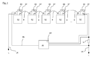
- the in the FIG. 1 schematically illustrated battery assembly has a number of secondary cells SZ, which are electrically connected in series by bridges B. One end and a start of the series connection is connected to load cables LK, via which the battery arrangement is connected to a load L.
- the load is just as little represented as a charger or a converter by means of which the secondary cells of the battery assembly are charged.
- each battery pole of each secondary cell SK a battery or cell unit BE is attached, preferably plugged.
- the battery or cell unit BE is connected via a cable to the respective other battery terminal of the secondary cell.
- Various sensors for monitoring the state of the secondary cells SZ are provided in the battery or cell units BE, in particular voltage sensors for monitoring the voltage across the battery poles of the secondary cells SZ, temperature sensors for monitoring the temperatures of the secondary cells SZ, fill level sensors for monitoring the electrolyte solution level in the secondary cells SZ ,
- the sensor provided for temperature measurement may comprise a temperature-voltage converter or a temperature-current converter which has direct contact with a battery terminal. Since battery poles usually extend into the interior of the battery or secondary cell, and the battery poles are good heat conductors, such an arrangement of the transducer directly at the battery pole, the temperature in the battery or the secondary cell can be detected with good accuracy.
- the battery or cell units BE have communication interface for wireless communication with a central unit ZE, which also has a communication interface for wireless communication.
- the communication interfaces can be [KS1] Zigbee interface.
- the first and the last secondary cell SZ of the series connection of the secondary cells SZ is connected via lines ML to the central unit ZE. This makes it possible to detect the voltage across the series connection by the central unit ZE.
- a shunt resistor N is arranged to detect the current that is output from the series circuit.
- the voltage across the shunt resistor N is detected by the central unit ZE and calculated from the current.
- any other type of current measurement can be used.
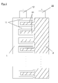
- the electrodes of a capacitive fill level sensor of the battery monitoring system may be so-called comb electrodes 1, 2. These have tines 11, 21, wherein the tines 11 of a first of the two electrodes of a pair of electrodes 1, 2 are located between two tines 21 of the second of the two electrodes.
- the electrodes 1, 2 are mounted on the outside of a housing 4 of the secondary cell, preferably glued.
- the electrodes preferably cover the entire area in which the liquid level of the electrolyte solution filled in the secondary cell can move.
- Connections 12, 22 of the electrodes are connected via lines not shown, each with a battery or cell unit BE.
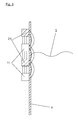
- the electric field constituted by the comb electrode pair 1, 2 mainly exists between the prongs 11, 21 (main field) and is not affected by the liquid level 3 in the secondary cell SZ.
- a so-called stray field is established, which also penetrates an area within the secondary cell SZ, in which the electrolyte solution is located.
- the material properties in a region of the electrolyte solution differ greatly from the properties of the region of the secondary cell SZ which is not filled with the electrolyte solution. Characteristic parameters of these material properties are the permittivity (dielectric conductivity), i. the permeability of a material for electric fields and the electrical conductivity. Both properties, but above all the permittivity, determine the electrical capacitance which is effective in the stray field and which can be measured at the electrode arrangement.
Abstract
Description
- Die vorliegende Erfindung betrifft ein Batterieüberwachungssystem, eine Batterieanordnung mit einer Vielzahl von Batterien mit einer oder mehreren in einem Gehäuse untergebrachten Sekundärzellen und mit diesem Batterieüberwachungssystem und ein Verfahren zum Betreiben dieser Batterieanordnung.
- Batterieanordnungen mit einer Vielzahl von Batterien, die wiederum eine oder mehrere in einem Gehäuse untergebrachte Sekundärzellen aufweisen, werden für verschiedene Zwecke verwendet. Häufig werden Batterieanordnungen an einem Standort verwendet. Bekannt sind aber auch Batterieanordnungen, die in Fahrzeugen eingesetzt werden, um die Stromversorgung in den Fahrzeugen zu ermöglichen.
- Batterieanordnungen, die an einem festen Standort verwendet werden, finden sich häufig in Anlagen zur unterbrechungsfreien Stromversorgung (USV). Batterieanordnungen in Anlagen zur unterbrechungsfreien Stromversorgung dienen der Sicherung der Stromversorgung eines einzelnen Verbrauchers oder eines Teilnetzes für den Fall, dass ein Versorgungsnetz ausfällt, an welches der einzelne Verbraucher oder das Teilnetz angeschlossen ist.
Solange das Versorgungsnetz nicht ausfällt, werden die Batterien der Batterieanordnungen von USV-Anlagen aufgeladen oder in einem aufgeladenen Zustand gehalten (Erhaltungsladung). - Bestandteil jeder Sekundärzelle einer Batterie ist ein Elektrolyt. Ohne Elektrolyt funktioniert eine galvanische Zelle nicht. Das Elektrolyt kann in verschiedenen Formen in einer Sekundärzelle vorhanden sein. So gibt es Batterien mit einer flüssigen Elektrolytlösung, Gelbatterien (auch VRLA-Akkumulator genannt) und Vliesbatterien. Für das Funktionieren der Batterie mit flüssiger Elektrolytlösung ist das Vorhandensein einer ausreichenden Menge der Elektrolytlösung von besonderer Bedeutung. Fehlt eine ausreichende Menge der Elektrolytlösung, muss Elektrolytlösung in die Zelle nachgefüllt werden. Eine Überwachung des Füllstands ist ein Anliegen der vorliegenden Erfindung.
- Jede Sekundärzelle einer Batterieanordnung hat auch bei gleicher Bauweise und Herstellung aller Sekundärzellen einer Batterieanordnung individuelle Eigenschaften. Diese individuellen Eigenschaften führen zu einem unterschiedlichen Verhalten beim Laden und Entladen einschließlich der Erhaltungsladung und der Selbstentladung. Dieses unterschiedliche Verhalten der Sekundärzellen führt dazu, dass spätestens nach mehreren Landungszyklen die Sekundärzellen unterschiedliche Ladungszustände haben. Das ist aber von Nachteil, da dann die nutzbare Kapazität der Batterieanordnung eingeschränkt ist. Eine Entladung der Batterieanordnung muss dann gestoppt werden, wenn der Ladezustand der schwächsten Sekundärzelle eine untere Schwelle erreicht hat, während die Aufladung der Batterieanordnung dann gestoppt werden muss, wenn die stärkste Sekundärzelle aufgeladen ist.
- Ebenso ist wichtig den Totalausfall einer Sekundärzelle in der Batterieanordnung zu erkennen, wenn zum Beispiel eine USV die Batterie im Ladeerhaltungsmodus betreibt damit im Bedarfsfall (Netzausfall) die Batterie auch zur Energielieferung genutzt werden kann. Der Ausfall einer einzigen Sekundärzelle führt nämlich zu einem vollständigen Ausfall der Batterieanordnung.
- Die Erfindung widmet sich dem Problem, die Sekundärzellen einer Batterieanordnung in einem gleichen Ladezustand zu halten, insbesondere wenn mehrere Batterien in Reihe (Serie) geschaltet sind und nur von einem Stromrichtergerät geladen bzw. entladen werden.
- Übergeordnet ist jedoch das Problem ein Batterieüberwachungssystem vorzuschlagen, welches in einer Batterieanordnung einfach montierbar ist, eine galvanische Trennung einer Zentraleinheit von an den Batterien oder Sekundärzellen angebrachten Batterie- oder Zelleneinheiten aufweist und eine einfache Kommunikation zwischen der Zentraleinheit und den Batterie- oder Zelleneinheiten ermöglicht.
- Dieses Problem wird dadurch gelöst, dass die Zentraleinheit und die Batterie- oder Zelleneinheiten Kommunikationsschnittstellen aufweisen, über welche zumindest die Zentraleinheit mit den Batterie- oder Zelleneinheiten oder umgekehrt drahtlos kommunizieren können. Es kann sich um Zigbee, WLAN, Bluetooth, IrDa oder andere Kommunikationsschnittstellen zur drahtlosen Kommunikation handeln.
- Eine drahtlose Kommunikation zwischen der Zentraleinheit einerseits und den Batterie- und oder Zelleneinheiten andererseits vereinfacht die Installation eines Batterieüberwachungssystems deutlich, da auf das Verlegen von Kabeln verzichtet werden kann. Dadurch benötigen die Zelleneinheiten nur die Isolationsspannung, die der einer Batteriezelle (z.B. 2,4 V) entspricht und nicht die der gesamten Batterie (z.B. 800 V).
- Insbesondere bei Batterieanordnungen mit einer großen Anzahl von Sekundärzellen, zum Beispiel 300 Sekundärzellen, ist das Verkabeln der Einheiten sehr aufwändig und materialintensiv. Dem kann durch die drahtlose Kommunikation abgeholfen werden.
- Zudem wird durch die Schnittstelle zur drahtlosen Kommunikation eine galvanische Trennung von Komponenten des Batterieüberwachungssystems erreicht.
- Gemäß der Erfindung können Batterie- oder Zelleneinheiten auf einem Batteriepol formschlüssig befestigt oder aufgesteckt werden. Dazu können die Batterie- oder Zelleneinheiten Ausnehmungen aufweisen, in welche die Batteriepole eingeführt werden können. Als Batteriepol in diesem Sinne ist nicht nur der Anschlusspol einer Batterie anzusehen, sondern auch der aus einem Gehäuse nach außen geführte Anschlusspol einer Sekundärzelle.
- Gemäß der Erfindung kann das Batterieüberwachungssystem Sensoren zur Messung aufweisen. Darunter kann ein Sensor zur Messung eines Füllstands einer Elektrolytlösung in den Batterien oder den Sekundärzellen sein. Andere Sensoren können Spannungssensoren und Temperatursensoren sein. Die Sensoren können ganz oder teilweise Teil der Batterie- oder Zelleneinheiten sein oder mit den Batterie- oder Zelleneinheiten verbindbar sein.
- Die Sensoren zur Messung des Füllstands können kapazitive Sensoren sein. Die kapazitiven Sensoren können ein Paar Elektroden aufweisen, die mit Abstand zueinander auf Gehäusen der Batterien bzw. der Sekundärzellen anbringbar sind. Die Elektroden können gabelähnlich, rechenähnlich oder kammähnlich gestaltet sein. Die Elektroden können Kammelektroden sein. Die Elektroden sind so zu einander angeordnet, dass Zinken einer Elektrode eines Elektrodenpaars in Zwischenräume zwischen Zinken einer anderen Elektrode des Elektrodenpaars eingreifen.
- Die Batterie- oder Zelleneinheiten können geeignet und eingerichtet sein, eine zur Funktion notwendige elektrische Energie aus der zu überwachenden Batterie oder Sekundärzelle zu beziehen. Die Batterie- oder Zelleneinheiten können dazu über ein Kabel oder eine Brücke mit einem Batteriepol verbunden sein, während die Batterie- oder Zelleneinheiten an dem anderen Batteriepol angebracht sind. Ebenso ist es möglich, dass die Batterie- oder Zelleneinheiten mit beiden Batteriepolen der Batterien oder Sekundärzellen über Kabel oder Brücken verbunden sind.
- Vorteilhaft kann von der Zentraleinheit die Leistung einzelner Komponenten der Batterie- oder Zelleneinheiten gesteuert werden. Das ermöglicht es, das Entladen oder Laden der Batterien oder Sekundärzellen zu beeinflussen. Die Batterien oder Sekundärzellen, denen die Batterie- oder Zelleneinheiten zugeordnet sind, deren Komponenten mehr verbrauchen als die Komponenten anderer Batterie- oder Zelleneinheiten, werden langsamer aufgeladen oder schneller entladen, als wenn eine Einflussnahme auf die Leistung der Komponenten unterbliebe. Dadurch lässt sich der Landungszustand der Sekundärzellen oder Batterien einer Batterieanordnung angleichen oder ausgleichen.
- Es kann insbesondere möglich sein, von der Zentraleinheit die Sendeleistung von Sendern der Batterie- oder Zelleneinheiten zu steuern. Dieses ist eine besonders einfache Möglichkeit, den Ladezustand der Batterien oder Sekundärzellen zu beeinflussen, da dazu keine besonderen energieverbrauchenden Komponenten in den Batterie- oder Zelleneinheiten vorgesehen sein müssen. Ebenso ist es möglich, dass von der Zentraleinheit die Leistung von LEDs der Batterie- oder Zelleneinheiten gesteuert werden. Bei diesen LEDs kann es sich um Status-LEDs handeln, die einen Zustand der Batterie- oder Zelleneinheiten oder den Zustand von Komponenten der Batterie- oder Zelleneinheiten anzeigen. Auch diese können in den Batterie- oder Zelleneinheiten vorhanden sein, so dass nur für das Entladen oder verzögerte Aufladen der Batterien oder Sekundärzellen keine besonderen Komponenten vorgesehen sein müssen.
- Gemäß der Erfindung ist es möglich, dass in den Batterie- oder Zelleneinheiten Widerstände vorgesehen sind, über welche die Batterien oder Sekundärzellen durch die Zentraleinheit gesteuert entlanden werden können, um den Ladezustand der Batterie oder Sekundärzelle, an welcher die Batterie- oder Zelleneinheiten mit den Widerständen vorgesehen sind, gezielt zu beeinflussen.
- Ein erfindungsgemäßes Batterieüberwachungssystem kann ein Teil einer erfindungsgemäßen Batterieanordnung umfassend eine Vielzahl von Batterien mit einer oder mehreren Sekundärzellen sein. Bei einer solchen Batterieanordnung sind die Batterie- oder Zelleneinheiten an den Batterien oder Sekundärzellen angebracht.
- Eine erfindungsgemäße Batterieanordnung kann so betrieben werden, dass Werte physikalischer Größen der Batterien oder Sekundärzellen, die mittels der Sensoren der Batterie- oder Zelleneinheiten gemessen werden, an die Zentraleinheit übermittelt werden und mittels der Zentraleinheit die Leistung von Komponenten der Batterie- oder Zelleneinheiten gesteuert wird, um einen gleichen Ladungszustand der Batterien oder Sekundärzellen zu erreichen.
- Weitere Merkmale und Vorteile der vorliegenden Erfindung werden deutlich anhand der nachfolgenden Beschreibung eines Ausführungsbeispiels unter Bezugnahme auf die beiliegenden Abbildungen. Darin zeigen in schematischer Darstellung:
- Fig. 1
- ein Batterieanordnung,
- Fig. 2
- Elektroden eines kapazitiven Füllstandssensors und
- Fig. 3
- einen Teil einer Batterie mit den Elektroden des kapazitiven Füllstandssensors im Schnitt.
- Die in der
Figur 1 schematisch dargestellte Batterieanordnung weist eine Anzahl von Sekundärzellen SZ auf, die durch Brücken B elektrisch in Reihe geschaltet sind. Ein Ende und ein Anfang der Reihenschaltung ist mit Lastkabeln LK verbunden, über die die Batterieanordnung mit einer Last L verbunden ist. Die Last ist ebenso wenig dargestellt wie ein Ladegerät oder ein Umrichter mittels dessen die Sekundärzellen der Batterieanordnung aufgeladen werden. - An je einem Batteriepol jeder Sekundärzelle SK ist eine Batterie- oder Zelleneinheit BE angebracht, vorzugsweise aufgesteckt. Die Batterie- oder Zelleneinheit BE ist über ein Kabel mit dem jeweils anderen Batteriepol der Sekundärzelle verbunden.
- In den Batterie- oder Zelleneinheiten BE sind verschiedene Sensoren zur Überwachung des Zustands der Sekundärzellen SZ vorgesehen, insbesondere Spannungssensoren zur Überwachung der Spannung an den Batteriepolen der Sekundärzellen SZ, Temperatursensoren zum Überwachen der Temperaturen der Sekundärzellen SZ, Füllstandssensoren zur Überwachung des Elektrolytlösungsfüllstands in den Sekundärzellen SZ.
- Der zur Temperaturmessung vorgesehene Sensor kann einen Temperatur-Spannungswandler oder einen Temperatur-Stromwandler aufweisen, der unmittelbaren Kontakt mit einem Batteriepol hat. Da Batteriepole in der Regel in das Innere der Batterie oder Sekundärzelle hineinreichen, und die Batteriepole gut Wärmeleiter sind, kann durch eine solche Anordnung der Wandler unmittelbar am Batteriepol die Temperatur in der Batterie oder der Sekundärzelle mit guter Genauigkeit erfasst werden.
- Die Batterie- oder Zelleneinheiten BE weisen Kommunikationsschnittstelle zur drahtlosen Kommunikation mit einer Zentraleinheit ZE auf, die dazu ebenfalls eine Kommunikationsschnittstelle zur drahtlosen Kommunikation aufweist. Bei den Kommunikationsschnittstellen kann es sich um [KS1]Zigbee-Schnittstelle handeln.
- Die Batterie- oder Zelleneinheiten BE und die Zentraleinheit ZE zusammen bilden ein erfindungsgemäßes Batteriemesssystem.
- Die erste und die letzte Sekundärzelle SZ der Reihenschaltung der Sekundärzellen SZ ist über Leitungen ML mit der Zentraleinheit ZE verbunden. Damit ist es möglich, die Spannung über der Reihenschaltung durch die Zentraleinheit ZE zu erfassen.
- Ebenso ist es möglich, dass in einem der Lastkabel LK ein Nebenwiderstand N angeordnet ist, um den Strom, der von der Reihenschaltung abgegeben wird, zu erfassen. Die Spannung über dem Nebenwiderstand N wird von der Zentraleinheit ZE erfasst und daraus der Strom berechnet. Selbstverständlich kann auch jede andere Art der Strommessung genutzt werden.
- Bei den Elektroden eines kapazitiven Füllstandssensors des erfindungsgemäßen Batterieüberwachungssystems kann es sich um sogenannte Kammelektroden 1, 2 handeln. Diese weisen Zinken 11, 21 auf, wobei die Zinken 11 einer ersten der beiden Elektroden eines Elektrodenpaares 1, 2 zwischen zwei Zinken 21 der zweiten der beiden Elektroden liegen. Die Elektroden 1, 2 sind auf der Außenseite eines Gehäuses 4 der Sekundärzelle befestigt, vorzugsweise aufgeklebt. Die Elektroden überdecken dabei vorzugsweise den gesamten Bereich, in dem sich der Flüssigkeitsspiegel der in die Sekundärzelle eingefüllten Elektrolytlösung bewegen kann. Anschlüsse 12, 22 der Elektroden sind über nicht dargestellte Leitungen mit je einer Batterie- oder Zelleneinheit BE verbunden.
- Durch das Anlegen einer Spannung zwischen den Zinken der beiden Elektroden eines der Elektrodenpaare 1, 2 wird ein elektrisches Feld aufgebaut. Das von dem Kammelektrodenpaar 1, 2 aufgebaute elektrische Feld besteht natürlich hauptsächlich zwischen den Zinken 1 1 , 21 (Hauptfeld) und wird nicht durch den Flüssigkeitsspiegel 3 in der Sekundärzelle SZ beeinflusst. Neben dem Hauptfeld wird aber auch ein sogenanntes Streufeld aufgebaut, das auch einen Bereich innerhalb der Sekundärzelle SZ durchdringt, in dem sich die Elektrolytlösung befindet. Die Materialeigenschaften in einem Bereich der Elektrolytlösung weichen stark von den Eigenschaften des nicht mit der Elektrolytlösung gefüllten Bereiches der Sekundärzelle SZ ab. Charakteristische Parameter dieser Materialeigenschaften sind die Permittivität (dielektrische Leitfähigkeit), d.h. die Durchlässigkeit eines Materials für elektrische Felder und die elektrische Leitfähigkeit. Beide Eigenschaften, vor allem aber die Permittivität , bestimmen die im Streufeld wirksame elektrische Kapazität, die an der Elektrodenanordnung messbar ist.
Claims (15)
- Batterieüberwachungssystem mit wenigstens einer Zentraleinheit (ZE) und an Batterien oder Sekundärzellen (SK) anbringbaren Batterie- oder Zelleneinheiten, wobei jede Batterie- oder Zelleneinheit Sensoren zum Erfassen physikalischer Größen in oder an der Batterie oder Sekundärzelle (SK) aufweist, und wobei die Zentraleinheit (ZE) und die Batterie- oder Zelleneinheiten (BE) Kommunikationsschnittstellen (BT) aufweisen, über welche zumindest die Zentraleinheit (ZE) mit den Batterie- oder Zelleneinheiten (BE) oder umgekehrt kommunizieren können,
dadurch gekennzeichnet,
dass die Kommunikationsschnittstellen (BT) Schnittstellen für eine drahtlose Kommunikation sind. - Batterieüberwachungssystem nach dem Oberbegriff des Anspruchs 1, insbesondere nach Anspruch 1, dadurch gekennzeichnet, dass die Batterie- oder Zelleneinheiten (BE) an einem Batteriepol formschlüssig befestigtbar oder aufsteckbar ist.
- Batterieüberwachungssystem nach dem Oberbegriff des Anspruchs 1 , insbesondere nach Anspruch 1 oder 2, dadurch gekennzeichnet, dass das Batterieüberwachungssystem Sensoren zur Messung eines Füllstands einer Elektrolytlösung in den Batterien oder den Sekundärzellen (SK) aufweist.
- Batterieüberwachungssystem nach Anspruch 3, dadurch gekennzeichnet, dass die Sensoren zur Messung des Füllstands Teil der Batterie- oder Zelleneinheiten (BE) sind oder mit den Batterie- oder Zelleneinheiten (BE) verbindbar sind.
- Batterieüberwachungssystem nach Anspruch 4, dadurch gekennzeichnet, dass die Sensoren zur Messung des Füllstands kapazitive Sensoren sind.
- Batterieüberwachungssystem nach Anspruch 5, dadurch gekennzeichnet, dass die Sensoren ein Paar Elektroden (1 , 2) aufweisen, die mit Abstand zueinander auf Gehäusen der Batterien bzw. der Sekundärzellen (SK) angebracht sind.
- Batterieüberwachungssystem nach Anspruch 6, dadurch gekennzeichnet, dass die Elektroden (1 , 2) gabelähnlich, rechenähnlich oder kammähnlich gestaltet sind
- Batterieüberwachungssystem nach Anspruch 7, dadurch gekennzeichnet, dass die Elektroden (1 , 2) so zu einander angeordnet sind, das Zinken (11) einer Elektrode (1) eines Elektrodenpaars (1, 2) in Zwischenräume zwischen Zinken (21) einer anderen Elektrode (2) des Elektrodepaars (1 , 2) eingreifen.
- Batterieüberwachungssystem nach dem Oberbegriff des Anspruchs 1 , insbesondere nach einem der Ansprüche 1 bis 8, dadurch gekennzeichnet, dass die Batterie- oder Zelleneinheiten (BE) geeignet und eingerichtet sind, eine zur Funktion notwendige elektrische Energie aus der zu überwachenden Batterie oder Sekundärzelle (SK) zu beziehen.
- Batterieüberwachungssystem nach Anspruch 9, dadurch gekennzeichnet, dass von der Zentraleinheit (ZE) die Leistung einzelner Komponenten der Batterie- oder Zelleneinheiten (BE) steuerbar ist.
- Batterieüberwachungssystem nach Anspruch 10, dadurch gekennzeichnet, dass von der Zentraleinheit (ZE) die Sendeleistung von Sendern der Batterie- oder Zelleneinheiten (BE) steuerbar ist.
- Batterieüberwachungssystem nach Anspruch 10 oder 1 1 , dadurch gekennzeichnet, dass von der Zentraleinheit (ZE) LEDs der Batterie- oder Zelleneinheiten (BE) steuerbar sind.
- Batterieüberwachungssystem nach Anspruch 12, dadurch gekennzeichnet, dass die LEDs Status-LEDs sind, die einen Zustand der Batterie- oder Zelleneinheiten (BE) oder den Zustand von Komponenten der Batterie- oder Zelleneinheiten (BE) anzeigen.
- Batterieanordnung aufweisend eine Vielzahl von Batterien mit einer oder mehreren Sekundärzellen (SK) und einem Batterieüberwachungssystem nach einem der Ansprüche 1 bis 12, dadurch gekennzeichnet, dass die Batterie- oder Zelleneinheiten (BE) an Batteriepolen der Batterien oder Sekundärzellen (SK) angebracht sind.
- Verfahren zum Betreiben dieser Batterieanordnung nach Anspruch 14, dadurch gekennzeichnet, dass mittels Sensoren der Batterie- oder Zelleneinheiten (BE) gemessene Werte physikalischer Größen der Batterien oder Sekundärzellen (SK) an die Zentraleinheit (ZE) übermittelt werden und mittels der Zentraleinheit die Leistung von Komponenten der Batterie- oder Zelleneinheiten (BE) gesteuert wird, um einen gleichen Ladungszustand der Batterien oder Sekundärzellen (SK) zu erreichen.
Priority Applications (2)
| Application Number | Priority Date | Filing Date | Title |
|---|---|---|---|
| ES14157257.8T ES2633985T3 (es) | 2014-02-28 | 2014-02-28 | Sistema de supervisión de batería, disposición de batería con el sistema de supervisión de batería y procedimiento para el funcionamiento de la disposición de batería |
| EP14157257.8A EP2913882B1 (de) | 2014-02-28 | 2014-02-28 | Batterieüberwachungssystem, Batterieanordnung mit dem Batterieüberwachungssystem und Verfahren zum Betreiben der Batterieanordnung |
Applications Claiming Priority (1)
| Application Number | Priority Date | Filing Date | Title |
|---|---|---|---|
| EP14157257.8A EP2913882B1 (de) | 2014-02-28 | 2014-02-28 | Batterieüberwachungssystem, Batterieanordnung mit dem Batterieüberwachungssystem und Verfahren zum Betreiben der Batterieanordnung |
Publications (2)
| Publication Number | Publication Date |
|---|---|
| EP2913882A1 true EP2913882A1 (de) | 2015-09-02 |
| EP2913882B1 EP2913882B1 (de) | 2017-05-03 |
Family
ID=50235945
Family Applications (1)
| Application Number | Title | Priority Date | Filing Date |
|---|---|---|---|
| EP14157257.8A Active EP2913882B1 (de) | 2014-02-28 | 2014-02-28 | Batterieüberwachungssystem, Batterieanordnung mit dem Batterieüberwachungssystem und Verfahren zum Betreiben der Batterieanordnung |
Country Status (2)
| Country | Link |
|---|---|
| EP (1) | EP2913882B1 (de) |
| ES (1) | ES2633985T3 (de) |
Cited By (1)
| Publication number | Priority date | Publication date | Assignee | Title |
|---|---|---|---|---|
| CN107749444A (zh) * | 2016-07-12 | 2018-03-02 | 罗伯特·博世有限公司 | 电池组模块和用于监测电池组模块的方法 |
Citations (4)
| Publication number | Priority date | Publication date | Assignee | Title |
|---|---|---|---|---|
| US20070190403A1 (en) * | 2005-06-14 | 2007-08-16 | Chin-Ho Wang | Device for detecting electrolyte overflow and energy storage device having the same |
| DE202007011399U1 (de) * | 2007-08-14 | 2008-09-18 | Raytheon Anschütz Gmbh | Batterieüberwachungssystem |
| WO2011117089A1 (de) * | 2010-03-24 | 2011-09-29 | Magna E-Car Systems Gmbh & Co Og | Überwachungssystem für eine energiespeicherzelle |
| DE102012210253A1 (de) * | 2011-11-18 | 2013-05-23 | Robert Bosch Gmbh | Verfahren zum Überwachen einer Batterie |
-
2014
- 2014-02-28 ES ES14157257.8T patent/ES2633985T3/es active Active
- 2014-02-28 EP EP14157257.8A patent/EP2913882B1/de active Active
Patent Citations (4)
| Publication number | Priority date | Publication date | Assignee | Title |
|---|---|---|---|---|
| US20070190403A1 (en) * | 2005-06-14 | 2007-08-16 | Chin-Ho Wang | Device for detecting electrolyte overflow and energy storage device having the same |
| DE202007011399U1 (de) * | 2007-08-14 | 2008-09-18 | Raytheon Anschütz Gmbh | Batterieüberwachungssystem |
| WO2011117089A1 (de) * | 2010-03-24 | 2011-09-29 | Magna E-Car Systems Gmbh & Co Og | Überwachungssystem für eine energiespeicherzelle |
| DE102012210253A1 (de) * | 2011-11-18 | 2013-05-23 | Robert Bosch Gmbh | Verfahren zum Überwachen einer Batterie |
Cited By (2)
| Publication number | Priority date | Publication date | Assignee | Title |
|---|---|---|---|---|
| CN107749444A (zh) * | 2016-07-12 | 2018-03-02 | 罗伯特·博世有限公司 | 电池组模块和用于监测电池组模块的方法 |
| CN107749444B (zh) * | 2016-07-12 | 2021-12-31 | 罗伯特·博世有限公司 | 电池组模块和用于监测电池组模块的方法 |
Also Published As
| Publication number | Publication date |
|---|---|
| EP2913882B1 (de) | 2017-05-03 |
| ES2633985T3 (es) | 2017-09-26 |
Similar Documents
| Publication | Publication Date | Title |
|---|---|---|
| EP2732295B1 (de) | Vorrichtung zum messen eines elektrischen stromes | |
| EP2169758B1 (de) | Nach galvanischen Prinzipien arbeitende elektrische Einrichtungen, wie beispielsweise Lithium-Ionen-Zelle, mit einer Betriebszustandssteuerung | |
| EP3301464B1 (de) | Energiespeichereinrichtung | |
| DE202011110740U1 (de) | Batterie mit mehreren Akkumulator-Zellen | |
| EP2858849B1 (de) | Verfahren zur bestimmung eines ohmschen innenwiderstandes eines batteriemoduls, batteriemanagementsystem und kraftfahrzeug | |
| EP2368304A2 (de) | Energiespeicheranordnung und verfahren zum betrieb einer derartigen anordnung | |
| DE102015002072A1 (de) | Einstellen von Ladungszuständen von Batteriezellen | |
| DE102016207033A1 (de) | Elektrische Energiespeichervorrichtung für ein Fahrzeugbordnetz, Fahrzeugbordnetz | |
| EP2704287A1 (de) | Zuschaltbare Ladungsausgleichsschaltung | |
| DE112017004066T5 (de) | Batteriesteuereinheit | |
| EP3259789B1 (de) | Überwachen einer zustandsgrösse wenigstens einer batteriezelle einer batterie | |
| EP2859368B1 (de) | Verfahren zur bestimmung eines ohmschen innenwiderstandes eines batteriemoduls, batteriemanagementsystem und kraftfahrzeug | |
| EP3079222B1 (de) | Energieversorgungsvorrichtung für ein batteriemanagementsystem | |
| EP2913882B1 (de) | Batterieüberwachungssystem, Batterieanordnung mit dem Batterieüberwachungssystem und Verfahren zum Betreiben der Batterieanordnung | |
| DE102013207187A1 (de) | Zeitgesteuerter Ladungsausgleich bei Batteriesystemen | |
| DE102019200510A1 (de) | Messanordnung, Hochvoltbatterie, Kraftfahrzeug und Verfahren zum Bestimmen einer komplexen Impedanz | |
| EP3314275B1 (de) | Messanordnung zum erkennen einer fehlfunktion in einer energiespeicheranordnung | |
| EP4067890A1 (de) | Detektion von feuchtigkeit in einem elektronischen schaltkreis | |
| EP3314276B1 (de) | Messanordnung zum erkennen einer fehlfunktion einer energiespeicheranordnung | |
| DE102012209177B4 (de) | Batteriesystem mit separat angeschlossener Bestimmungsschaltung sowie Batterie und Kraftfahrzeug mit Batteriesystem | |
| DE102013203971A1 (de) | Verfahren zur Herstellung einer Temperaturmessvorrichtung zur Erfassung einer Temperatur von zumindest einem Element eines elektrochemischen Energiespeichers | |
| DE102017207001A1 (de) | Verfahren zur Durchführung eines Ladevorgangs bei einem Batteriesystem | |
| WO2012146434A1 (de) | Verfahren zum betreiben einer speichervorrichtung zum speichern von elektrischer energie und speichervorrichtung zum speichern von elektrischer energie | |
| DE102010011277B4 (de) | Batteriesystem und Verfahren zum Ändern des Ladungszustands eines Batteriesystems | |
| DE102008054532A1 (de) | Batteriemodul |
Legal Events
| Date | Code | Title | Description |
|---|---|---|---|
| PUAI | Public reference made under article 153(3) epc to a published international application that has entered the european phase |
Free format text: ORIGINAL CODE: 0009012 |
|
| 17P | Request for examination filed |
Effective date: 20150402 |
|
| AK | Designated contracting states |
Kind code of ref document: A1 Designated state(s): AL AT BE BG CH CY CZ DE DK EE ES FI FR GB GR HR HU IE IS IT LI LT LU LV MC MK MT NL NO PL PT RO RS SE SI SK SM TR |
|
| 17Q | First examination report despatched |
Effective date: 20150825 |
|
| GRAP | Despatch of communication of intention to grant a patent |
Free format text: ORIGINAL CODE: EPIDOSNIGR1 |
|
| INTG | Intention to grant announced |
Effective date: 20161115 |
|
| GRAS | Grant fee paid |
Free format text: ORIGINAL CODE: EPIDOSNIGR3 |
|
| GRAA | (expected) grant |
Free format text: ORIGINAL CODE: 0009210 |
|
| AK | Designated contracting states |
Kind code of ref document: B1 Designated state(s): AL AT BE BG CH CY CZ DE DK EE ES FI FR GB GR HR HU IE IS IT LI LT LU LV MC MK MT NL NO PL PT RO RS SE SI SK SM TR |
|
| REG | Reference to a national code |
Ref country code: GB Ref legal event code: FG4D Free format text: NOT ENGLISH |
|
| REG | Reference to a national code |
Ref country code: AT Ref legal event code: REF Ref document number: 890930 Country of ref document: AT Kind code of ref document: T Effective date: 20170515 Ref country code: CH Ref legal event code: EP |
|
| REG | Reference to a national code |
Ref country code: IE Ref legal event code: FG4D Free format text: LANGUAGE OF EP DOCUMENT: GERMAN |
|
| REG | Reference to a national code |
Ref country code: DE Ref legal event code: R096 Ref document number: 502014003599 Country of ref document: DE |
|
| REG | Reference to a national code |
Ref country code: NL Ref legal event code: FP |
|
| REG | Reference to a national code |
Ref country code: LT Ref legal event code: MG4D |
|
| REG | Reference to a national code |
Ref country code: ES Ref legal event code: FG2A Ref document number: 2633985 Country of ref document: ES Kind code of ref document: T3 Effective date: 20170926 |
|
| PG25 | Lapsed in a contracting state [announced via postgrant information from national office to epo] |
Ref country code: HR Free format text: LAPSE BECAUSE OF FAILURE TO SUBMIT A TRANSLATION OF THE DESCRIPTION OR TO PAY THE FEE WITHIN THE PRESCRIBED TIME-LIMIT Effective date: 20170503 Ref country code: NO Free format text: LAPSE BECAUSE OF FAILURE TO SUBMIT A TRANSLATION OF THE DESCRIPTION OR TO PAY THE FEE WITHIN THE PRESCRIBED TIME-LIMIT Effective date: 20170803 Ref country code: GR Free format text: LAPSE BECAUSE OF FAILURE TO SUBMIT A TRANSLATION OF THE DESCRIPTION OR TO PAY THE FEE WITHIN THE PRESCRIBED TIME-LIMIT Effective date: 20170804 Ref country code: FI Free format text: LAPSE BECAUSE OF FAILURE TO SUBMIT A TRANSLATION OF THE DESCRIPTION OR TO PAY THE FEE WITHIN THE PRESCRIBED TIME-LIMIT Effective date: 20170503 Ref country code: LT Free format text: LAPSE BECAUSE OF FAILURE TO SUBMIT A TRANSLATION OF THE DESCRIPTION OR TO PAY THE FEE WITHIN THE PRESCRIBED TIME-LIMIT Effective date: 20170503 |
|
| PG25 | Lapsed in a contracting state [announced via postgrant information from national office to epo] |
Ref country code: SE Free format text: LAPSE BECAUSE OF FAILURE TO SUBMIT A TRANSLATION OF THE DESCRIPTION OR TO PAY THE FEE WITHIN THE PRESCRIBED TIME-LIMIT Effective date: 20170503 Ref country code: IS Free format text: LAPSE BECAUSE OF FAILURE TO SUBMIT A TRANSLATION OF THE DESCRIPTION OR TO PAY THE FEE WITHIN THE PRESCRIBED TIME-LIMIT Effective date: 20170903 Ref country code: PL Free format text: LAPSE BECAUSE OF FAILURE TO SUBMIT A TRANSLATION OF THE DESCRIPTION OR TO PAY THE FEE WITHIN THE PRESCRIBED TIME-LIMIT Effective date: 20170503 Ref country code: RS Free format text: LAPSE BECAUSE OF FAILURE TO SUBMIT A TRANSLATION OF THE DESCRIPTION OR TO PAY THE FEE WITHIN THE PRESCRIBED TIME-LIMIT Effective date: 20170503 Ref country code: LV Free format text: LAPSE BECAUSE OF FAILURE TO SUBMIT A TRANSLATION OF THE DESCRIPTION OR TO PAY THE FEE WITHIN THE PRESCRIBED TIME-LIMIT Effective date: 20170503 Ref country code: BG Free format text: LAPSE BECAUSE OF FAILURE TO SUBMIT A TRANSLATION OF THE DESCRIPTION OR TO PAY THE FEE WITHIN THE PRESCRIBED TIME-LIMIT Effective date: 20170803 |
|
| PG25 | Lapsed in a contracting state [announced via postgrant information from national office to epo] |
Ref country code: RO Free format text: LAPSE BECAUSE OF FAILURE TO SUBMIT A TRANSLATION OF THE DESCRIPTION OR TO PAY THE FEE WITHIN THE PRESCRIBED TIME-LIMIT Effective date: 20170503 Ref country code: DK Free format text: LAPSE BECAUSE OF FAILURE TO SUBMIT A TRANSLATION OF THE DESCRIPTION OR TO PAY THE FEE WITHIN THE PRESCRIBED TIME-LIMIT Effective date: 20170503 Ref country code: CZ Free format text: LAPSE BECAUSE OF FAILURE TO SUBMIT A TRANSLATION OF THE DESCRIPTION OR TO PAY THE FEE WITHIN THE PRESCRIBED TIME-LIMIT Effective date: 20170503 Ref country code: SK Free format text: LAPSE BECAUSE OF FAILURE TO SUBMIT A TRANSLATION OF THE DESCRIPTION OR TO PAY THE FEE WITHIN THE PRESCRIBED TIME-LIMIT Effective date: 20170503 Ref country code: EE Free format text: LAPSE BECAUSE OF FAILURE TO SUBMIT A TRANSLATION OF THE DESCRIPTION OR TO PAY THE FEE WITHIN THE PRESCRIBED TIME-LIMIT Effective date: 20170503 |
|
| REG | Reference to a national code |
Ref country code: DE Ref legal event code: R097 Ref document number: 502014003599 Country of ref document: DE |
|
| REG | Reference to a national code |
Ref country code: FR Ref legal event code: PLFP Year of fee payment: 5 |
|
| PG25 | Lapsed in a contracting state [announced via postgrant information from national office to epo] |
Ref country code: SM Free format text: LAPSE BECAUSE OF FAILURE TO SUBMIT A TRANSLATION OF THE DESCRIPTION OR TO PAY THE FEE WITHIN THE PRESCRIBED TIME-LIMIT Effective date: 20170503 |
|
| PLBE | No opposition filed within time limit |
Free format text: ORIGINAL CODE: 0009261 |
|
| STAA | Information on the status of an ep patent application or granted ep patent |
Free format text: STATUS: NO OPPOSITION FILED WITHIN TIME LIMIT |
|
| 26N | No opposition filed |
Effective date: 20180206 |
|
| PG25 | Lapsed in a contracting state [announced via postgrant information from national office to epo] |
Ref country code: SI Free format text: LAPSE BECAUSE OF FAILURE TO SUBMIT A TRANSLATION OF THE DESCRIPTION OR TO PAY THE FEE WITHIN THE PRESCRIBED TIME-LIMIT Effective date: 20170503 |
|
| REG | Reference to a national code |
Ref country code: CH Ref legal event code: PL |
|
| PG25 | Lapsed in a contracting state [announced via postgrant information from national office to epo] |
Ref country code: MC Free format text: LAPSE BECAUSE OF FAILURE TO SUBMIT A TRANSLATION OF THE DESCRIPTION OR TO PAY THE FEE WITHIN THE PRESCRIBED TIME-LIMIT Effective date: 20170503 Ref country code: MT Free format text: LAPSE BECAUSE OF FAILURE TO SUBMIT A TRANSLATION OF THE DESCRIPTION OR TO PAY THE FEE WITHIN THE PRESCRIBED TIME-LIMIT Effective date: 20170503 |
|
| REG | Reference to a national code |
Ref country code: DE Ref legal event code: R084 Ref document number: 502014003599 Country of ref document: DE |
|
| REG | Reference to a national code |
Ref country code: IE Ref legal event code: MM4A |
|
| REG | Reference to a national code |
Ref country code: BE Ref legal event code: MM Effective date: 20180228 |
|
| PG25 | Lapsed in a contracting state [announced via postgrant information from national office to epo] |
Ref country code: CH Free format text: LAPSE BECAUSE OF NON-PAYMENT OF DUE FEES Effective date: 20180228 Ref country code: LI Free format text: LAPSE BECAUSE OF NON-PAYMENT OF DUE FEES Effective date: 20180228 Ref country code: LU Free format text: LAPSE BECAUSE OF NON-PAYMENT OF DUE FEES Effective date: 20180228 |
|
| PG25 | Lapsed in a contracting state [announced via postgrant information from national office to epo] |
Ref country code: IE Free format text: LAPSE BECAUSE OF NON-PAYMENT OF DUE FEES Effective date: 20180228 |
|
| PG25 | Lapsed in a contracting state [announced via postgrant information from national office to epo] |
Ref country code: BE Free format text: LAPSE BECAUSE OF NON-PAYMENT OF DUE FEES Effective date: 20180228 |
|
| PG25 | Lapsed in a contracting state [announced via postgrant information from national office to epo] |
Ref country code: TR Free format text: LAPSE BECAUSE OF FAILURE TO SUBMIT A TRANSLATION OF THE DESCRIPTION OR TO PAY THE FEE WITHIN THE PRESCRIBED TIME-LIMIT Effective date: 20170503 |
|
| PGFP | Annual fee paid to national office [announced via postgrant information from national office to epo] |
Ref country code: GB Payment date: 20200219 Year of fee payment: 7 Ref country code: ES Payment date: 20200322 Year of fee payment: 7 Ref country code: NL Payment date: 20200219 Year of fee payment: 7 Ref country code: IT Payment date: 20200228 Year of fee payment: 7 |
|
| PG25 | Lapsed in a contracting state [announced via postgrant information from national office to epo] |
Ref country code: PT Free format text: LAPSE BECAUSE OF FAILURE TO SUBMIT A TRANSLATION OF THE DESCRIPTION OR TO PAY THE FEE WITHIN THE PRESCRIBED TIME-LIMIT Effective date: 20170503 |
|
| PG25 | Lapsed in a contracting state [announced via postgrant information from national office to epo] |
Ref country code: CY Free format text: LAPSE BECAUSE OF FAILURE TO SUBMIT A TRANSLATION OF THE DESCRIPTION OR TO PAY THE FEE WITHIN THE PRESCRIBED TIME-LIMIT Effective date: 20170503 Ref country code: HU Free format text: LAPSE BECAUSE OF FAILURE TO SUBMIT A TRANSLATION OF THE DESCRIPTION OR TO PAY THE FEE WITHIN THE PRESCRIBED TIME-LIMIT; INVALID AB INITIO Effective date: 20140228 Ref country code: MK Free format text: LAPSE BECAUSE OF NON-PAYMENT OF DUE FEES Effective date: 20170503 |
|
| PGFP | Annual fee paid to national office [announced via postgrant information from national office to epo] |
Ref country code: FR Payment date: 20200219 Year of fee payment: 7 |
|
| PG25 | Lapsed in a contracting state [announced via postgrant information from national office to epo] |
Ref country code: AL Free format text: LAPSE BECAUSE OF FAILURE TO SUBMIT A TRANSLATION OF THE DESCRIPTION OR TO PAY THE FEE WITHIN THE PRESCRIBED TIME-LIMIT Effective date: 20170503 |
|
| REG | Reference to a national code |
Ref country code: DE Ref legal event code: R082 Ref document number: 502014003599 Country of ref document: DE Representative=s name: FRITZ PATENT- UND RECHTSANWAELTE PARTNERSCHAFT, DE Ref country code: DE Ref legal event code: R081 Ref document number: 502014003599 Country of ref document: DE Owner name: WEISSGERBER ENGINEERING GMBH, DE Free format text: FORMER OWNER: AEG POWER SOLUTIONS GMBH, 59581 WARSTEIN, DE |
|
| GBPC | Gb: european patent ceased through non-payment of renewal fee |
Effective date: 20210228 |
|
| REG | Reference to a national code |
Ref country code: AT Ref legal event code: PC Ref document number: 890930 Country of ref document: AT Kind code of ref document: T Owner name: WEISSGERBER EINGINEERING GMBH, DE Effective date: 20211011 |
|
| REG | Reference to a national code |
Ref country code: NL Ref legal event code: MM Effective date: 20210301 |
|
| PG25 | Lapsed in a contracting state [announced via postgrant information from national office to epo] |
Ref country code: NL Free format text: LAPSE BECAUSE OF NON-PAYMENT OF DUE FEES Effective date: 20210301 |
|
| REG | Reference to a national code |
Ref country code: AT Ref legal event code: HC Ref document number: 890930 Country of ref document: AT Kind code of ref document: T Owner name: WEISSGERBER ENGINEERING GMBH, DE Effective date: 20211214 |
|
| PG25 | Lapsed in a contracting state [announced via postgrant information from national office to epo] |
Ref country code: FR Free format text: LAPSE BECAUSE OF NON-PAYMENT OF DUE FEES Effective date: 20210228 Ref country code: GB Free format text: LAPSE BECAUSE OF NON-PAYMENT OF DUE FEES Effective date: 20210228 |
|
| PG25 | Lapsed in a contracting state [announced via postgrant information from national office to epo] |
Ref country code: IT Free format text: LAPSE BECAUSE OF NON-PAYMENT OF DUE FEES Effective date: 20210228 |
|
| PGFP | Annual fee paid to national office [announced via postgrant information from national office to epo] |
Ref country code: AT Payment date: 20220217 Year of fee payment: 9 |
|
| REG | Reference to a national code |
Ref country code: ES Ref legal event code: FD2A Effective date: 20220517 |
|
| PG25 | Lapsed in a contracting state [announced via postgrant information from national office to epo] |
Ref country code: ES Free format text: LAPSE BECAUSE OF NON-PAYMENT OF DUE FEES Effective date: 20210301 |
|
| PGFP | Annual fee paid to national office [announced via postgrant information from national office to epo] |
Ref country code: DE Payment date: 20230228 Year of fee payment: 10 |
|
| P01 | Opt-out of the competence of the unified patent court (upc) registered |
Effective date: 20230616 |
|
| REG | Reference to a national code |
Ref country code: AT Ref legal event code: MM01 Ref document number: 890930 Country of ref document: AT Kind code of ref document: T Effective date: 20230228 |
|
| PG25 | Lapsed in a contracting state [announced via postgrant information from national office to epo] |
Ref country code: AT Free format text: LAPSE BECAUSE OF NON-PAYMENT OF DUE FEES Effective date: 20230228 |