EP2913824A1 - Strip for a nuclear fuel assembly spacer grid - Google Patents
Strip for a nuclear fuel assembly spacer grid Download PDFInfo
- Publication number
- EP2913824A1 EP2913824A1 EP15161691.9A EP15161691A EP2913824A1 EP 2913824 A1 EP2913824 A1 EP 2913824A1 EP 15161691 A EP15161691 A EP 15161691A EP 2913824 A1 EP2913824 A1 EP 2913824A1
- Authority
- EP
- European Patent Office
- Prior art keywords
- tab
- strip
- wall portion
- strip according
- spring
- Prior art date
- Legal status (The legal status is an assumption and is not a legal conclusion. Google has not performed a legal analysis and makes no representation as to the accuracy of the status listed.)
- Granted
Links
Images


Classifications
-
- G—PHYSICS
- G21—NUCLEAR PHYSICS; NUCLEAR ENGINEERING
- G21C—NUCLEAR REACTORS
- G21C3/00—Reactor fuel elements and their assemblies; Selection of substances for use as reactor fuel elements
- G21C3/30—Assemblies of a number of fuel elements in the form of a rigid unit
- G21C3/32—Bundles of parallel pin-, rod-, or tube-shaped fuel elements
- G21C3/34—Spacer grids
- G21C3/356—Spacer grids being provided with fuel element supporting members
- G21C3/3563—Supporting members formed only by deformations in the strips
-
- G—PHYSICS
- G21—NUCLEAR PHYSICS; NUCLEAR ENGINEERING
- G21C—NUCLEAR REACTORS
- G21C3/00—Reactor fuel elements and their assemblies; Selection of substances for use as reactor fuel elements
- G21C3/30—Assemblies of a number of fuel elements in the form of a rigid unit
- G21C3/32—Bundles of parallel pin-, rod-, or tube-shaped fuel elements
- G21C3/34—Spacer grids
- G21C3/356—Spacer grids being provided with fuel element supporting members
-
- G—PHYSICS
- G21—NUCLEAR PHYSICS; NUCLEAR ENGINEERING
- G21C—NUCLEAR REACTORS
- G21C3/00—Reactor fuel elements and their assemblies; Selection of substances for use as reactor fuel elements
- G21C3/30—Assemblies of a number of fuel elements in the form of a rigid unit
- G21C3/32—Bundles of parallel pin-, rod-, or tube-shaped fuel elements
- G21C3/34—Spacer grids
- G21C3/352—Spacer grids formed of assembled intersecting strips
-
- G—PHYSICS
- G21—NUCLEAR PHYSICS; NUCLEAR ENGINEERING
- G21C—NUCLEAR REACTORS
- G21C3/00—Reactor fuel elements and their assemblies; Selection of substances for use as reactor fuel elements
- G21C3/30—Assemblies of a number of fuel elements in the form of a rigid unit
- G21C3/32—Bundles of parallel pin-, rod-, or tube-shaped fuel elements
- G21C3/322—Means to influence the coolant flow through or around the bundles
-
- Y—GENERAL TAGGING OF NEW TECHNOLOGICAL DEVELOPMENTS; GENERAL TAGGING OF CROSS-SECTIONAL TECHNOLOGIES SPANNING OVER SEVERAL SECTIONS OF THE IPC; TECHNICAL SUBJECTS COVERED BY FORMER USPC CROSS-REFERENCE ART COLLECTIONS [XRACs] AND DIGESTS
- Y02—TECHNOLOGIES OR APPLICATIONS FOR MITIGATION OR ADAPTATION AGAINST CLIMATE CHANGE
- Y02E—REDUCTION OF GREENHOUSE GAS [GHG] EMISSIONS, RELATED TO ENERGY GENERATION, TRANSMISSION OR DISTRIBUTION
- Y02E30/00—Energy generation of nuclear origin
- Y02E30/30—Nuclear fission reactors
Definitions
- the present invention relates to a strip for a nuclear fuel assembly spacer grid comprising interlaced strips defining a lattice of cells for receiving fuel rods and allowing flow of a coolant in a flow direction.
- US 4 879 090 illustrates on Figure 5 thereof a peripheral strip for a nuclear fuel assembly spacer grid, the peripheral strip comprising wall portions to delimit cells and on each wall portion a spring formed by a tab cut out in the strip and motion limiters formed as a pair of bosses embossed in the strip at a distance from the tab.
- a coolant fluid e.g. water
- the spring and the motion limiters provided on each wall portion protrude from the plane of the wall portion towards the center of the same cell delimited by the wall portion and partially obstruct the coolant fluid flow channel.
- An object of the invention is to provide a strip for a nuclear fuel assembly spacer grid limiting the flow resistance of the spacer grid whilst allowing suitable support for the nuclear fuel rods during the whole fuel assembly lifetime and good manufacturability.
- the invention proposes a strip for a nuclear fuel assembly spacer grid for a nuclear fuel assembly spacer grid comprising interlaced strips defining a lattice of cells for receiving fuel rods and allowing flow of a coolant in a flow direction, the strip being of the type comprising a wall portion for delimiting a cell, a spring formed in the strip and provided on the wall portion for biasing the fuel rod extending through the cell away from the wall portion, the spring comprising a cantilevered tab formed in the strip and a contact portion formed at least partially in the tab and protruding from the tab for contacting the fuel rod received in the cell.
- the strip comprises one or several of the following features, taken in isolation or in any technically feasible combination:
- the invention also relates to a spacer grid comprising interlaced strips defining a lattice of cells for receiving fuel rods and allowing flow of a coolant axially upwardly through the spacer grid, at least one of the interlaced strips being a strip as defined above.
- the invention further relates to a nuclear fuel assembly comprising a bundle of fuel rods and an armature for supporting the fuel rods, the armature comprising at least one spacer grid as defined above.
- the nuclear fuel assembly 2 for a pressurized water reactor (PWR) illustrated on Figure 1 comprises a bundle of nuclear fuel rods 4 and an armature 6 for supporting the fuel rods 4.
- the PWR fuel assembly 2 is elongated along an assembly axis L extending vertically when the fuel assembly 2 is disposed inside a nuclear reactor.
- the armature 6 comprises a lower nozzle 8, an upper nozzle 10, a plurality of guide-tubes 12 and a plurality of spacer grids 14.
- the guide-tubes 12 extend parallel to assembly axis L and connect the lower nozzle 8 to the upper nozzle 10 and maintain a predetermined spacing along assembly axis L between the nozzles 8, 10. Each guide-tube 12 opens upwards through the upper nozzle 10 for allowing insertion of a control rod into the guide-tube 12.
- the nuclear fuel assembly 2 for a boiling water reactor (BWR) illustrated on Figure 2 is also elongated along an assembly axis L extending vertically when the fuel assembly 2 is disposed inside a nuclear reactor.
- the BWR fuel assembly 2 comprises a bundle of nuclear fuel rods 4, an armature for maintaining the fuel rods 4 and a tubular fuel channel 15 surrounding the bundle of fuel rods 4.
- the armature typically comprises a lower nozzle and an upper nozzle spaced along assembly axis L, at least one water channel 13 arranged within the bundle of fuel rods 4 and a plurality of spacer grids 14 distributed along the bundle of fuel rods 4.
- the fuel rods 4, the water channel 13 and the fuel channel 15 extend between the lower nozzle and the upper nozzle, with the water channel 13 and the fuel channel 15 connecting the lower nozzle and the upper nozzle.
- the water channel 13 extends parallel to the fuel rods 4.
- the water channel 13 is arranged for channeling a coolant/moderator flow separately from the bundle of fuel rods 4.
- the fuel channel 15 extends parallel to the fuel rods 4.
- the fuel channel 15 encases the bundle of fuel rods 4 and the water channel 13.
- the fuel channel 15 is arranged for channeling a coolant/moderator flow between and about the fuel rods 4.
- the PWR and BWR spacer grids 14 are distributed in spaced relationship along the fuel rods 4.
- Each spacer grid 14 extends transversely to the assembly axis L.
- Each fuel rod 4 comprises a tubular cladding, pellets of nuclear fuel stacked inside the cladding and caps closing the ends of the cladding.
- Each fuel rod 4 extends parallel to assembly axis L through the spacer grids 14 with being supported transversely and longitudinally relative to assembly axis L by the spacer grids 14.
- the fuel assembly 2 is placed in a nuclear reactor with the lower nozzle 8 resting on a bottom plate of the reactor and the assembly axis L being substantially vertical.
- a coolant flows upwardly along the fuel assembly 2 with flowing between the fuel rods 4 and through the nozzles 8, 10 and the spacer grids 14 as illustrated by arrows F on Figures 1 and 2 .
- the spacer grids 14 may be similar to each other and one spacer grid 14 according to the invention will be further described with reference to Figures 3 - 7 .
- the spacer grid 14 comprises a plurality of interlaced metallic strips 16 defining a lattice of cells 18 each for receiving one fuel rod 4, only a few cells 18 being illustrated on Figure 3 .
- the interlaced strips 16 also define a plurality of cells for receiving PWR guide-tubes 12, the spacer grid 14 being secured to the guide-tubes 12, e.g. by welding.
- the at least one BWR water channel 13 typically replaces one or several fuel rods 4 in the lattice
- the interlaced strips define an aperture for receiving the water channel 13 and the spacer grid 14 is secured to the water channel 13, e.g. by welding.
- cells 18 for receiving fuel rods 4 are illustrated on Figure 3 and in the following, the term "cell” refer to the cells 18 for receiving fuel rods 4.
- Each cell 18 is tubular and extends along a cell axis A.
- the cell axis A is to be parallel to the assembly axis L (perpendicular to Figure 3 ) when the spacer grid 14 is assembled in the fuel assembly 2 ( Figures 1 and 2 ).
- the cell axes A of the different cells 18 are parallel.
- Each cell 18 is delimited by four wall portions 20 of two pairs of intersecting strips 16, the strips 16 of each pair extending parallel to one another.
- One wall portion 20 of each pair of opposite wall portions 20 delimiting a cell 18 has an elastic spring 22 formed in the wall portion 20 and protruding in a free state towards the center of the cell 18, and the other wall portion 20 of each pair of opposite wall portions 20 has a rigid dimple 24 formed in the wall portion 20 and protruding towards the center of the cell 18.
- each cell 18 The springs 22 and dimples 24 provided on the wall portions 20 of each cell 18 are arranged such that a fuel rod 4 extending through the cell 18 is biased transversely by the springs 22 against the dimples 24 to support the fuel rod 4 transversely and longitudinally relative to the cell axis A.
- Each wall portion 20 delimiting two adjacent cells 18 has a spring 22 protruding on a face of the wall portion 20 in one of the cells 18 and a dimple 24 protruding on the opposite face of the wall portion 20 in the other cell 18.
- Each wall portion 20 delimiting only one cell 18 has either a spring 22 or a dimple 24.
- Figure 4 illustrates a plurality of the wall portions 20 of a strip 16, each of these wall portions 20 being adapted to delimit two cells 18, one on each side of the strip 16.
- the coolant flows upwardly through each cell 18 in the flow direction F represented on Figure 4 from an upstream lower edge 26 to a downstream upper edge 28 of the strip 16.
- the flow direction F is parallel to the cell axis A.
- Each wall portion 20 extends from the lower edge 26 to the upper edge 28.
- the wall portions 20 are separated by slits 30 provided on the lower edge 26 and extending substantially to the half-height of the strip 16 for engagement with a series of corresponding slits 30 provided on the upper edge 28 and extending substantially to the half-height of an intersecting strip 16.
- the strip 16 optionally comprises fins 32 protruding upwardly from the upper edge 28, each fin 32 being inclined relative to the cell axis A for imparting helical motion to the coolant fluid flowing through the cells 18 and enhancing heat exchange between the coolant and the fuel rods 4.
- the strip 16 comprises on each of the illustrated wall portions 20 a spring 22, a dimple 24 and a motion limiter 34 each formed in the strip 16 and thus being integrally one-piece with the strip 16.
- each wall portion 20 protrude on the same face of the strip 16, whereas the dimple 24 protrudes on the opposite face of the strip 16.
- the dimples 24 are alternately disposed below and above the springs 22 on the adjacent wall portions 20. Interlaced strips 16 thus can be arranged such that a spring 22 provided on a wall portion 20 of a strip 16 delimiting a cell 18 faces a dimple 24 provided on the opposite wall portion 20 of another strip 16 delimiting the cell 18.
- the springs 22 of the strip 16 are identical and one spring 22 is further described with reference to Figures 5 - 7 .
- the spring 22 illustrated on Figure 5 comprises a flexible cantilevered tab 36 and a contact portion 38 cut out in the strip 16.
- the tab 36 is delimited in the strip 16 by an elongated curved slot 40 of closed contour.
- the tab 36 is delimited between the slot 40 and the connection line 46 joining the opposed ends 48 of the slot 40.
- the ends 48 are preferably circular and enlarged to limit mechanical local peak stresses.
- the line 46 is perpendicular to the cell axis A.
- the tab 36 is connected to the wall portion 20 along the line 46.
- the tab 36 extends downwardly in cantilevered fashion towards the upstream lower edge 26 and has an upper base 42 connected to the wall portion 20 and a lower free tip 44.
- the tab 36 is converging towards the free tip 44.
- the slot 40 is generally U-shape with diverging branches (or V-shape with a rounded tip).
- the tab 36 In a free state of the spring 22, the tab 36 is inclined relative to the wall portion 20 and extends downwardly and away from the wall portion 20 towards the center of the cell 18 delimited by the wall portion 20.
- the tab 36 is elastically flexible by elastic deformation of the tab 36 with rotation of the tab 36 around a rotation axis substantially coinciding with the line 46. The flexibility of the tab can be adjusted by adjusting the diameter of the ends 48 of the slot 40.
- the contact portion 38 is formed exclusively in the tab 36 and protrudes from the tab 36 opposite the wall portion 20 and towards the center of a cell 18 delimited by the wall portion 20.
- the contact portion 38 is integrally one-piece with the tab 36.
- the contact portion 38 is provided in the form of an arched bridge cut out in the tab 36.
- the contact portion 38 is elongated in the direction of the cell axis A, the two ends of the contact portion 38 connected to the tab 36 being aligned in the direction of the cell axis A.
- the contact portion 38 is formed as a lancing delimited between two openings 52 extending substantially parallel to each other in the direction of the cell axis A.
- the motion limiter 34 associated to the spring 22 is formed in the strip 16 at a distance from the spring 22 and protrudes from the wall portion 20 on the same side than the corresponding spring 22.
- the motion limiter 34 is a bulge of curved perimeter formed in the strip 16, for instance of circular perimeter as illustrated on Figure 5 with a risen portion 56 and an apex 62.
- the motion limiter 34 is disposed below or above the corresponding spring 22 ( Figure 3 ).
- the contact portion 38 contacts the outer surface of a fuel rod 4 extending through a cell 18 delimited by the wall portion 20 with the tab 36 being elastically deformed towards the wall portion 20.
- the spring 22 thus biases the fuel rod 4 away from the wall portion 20 (toward the right on Figure 7 ) in contact with a dimple 24 provided on the opposite wall portion 20 delimiting the cell 18.
- the free tip 44 of the tab 36 extends substantially in the plane of the wall portion 20 and the height H of the contact portion 38 relative to the wall portion 20 is superior to the height h of the apex 62 of the motion limiter 34.
- the coolant flows through the cell 18 and around the fuel rod 4 upwardly at high speed in the flow direction F parallel to the cell axis A. This causes transverse vibration of the fuel rod 4 inside the cell 18. Transverse vibrations may also occur during transportation from manufacturing plant to power plant and during handling of the fuel assembly 2.
- the motion limiter 34 is rigid and limits movements of a fuel rod 4 towards the wall portion 20 against the action of the spring 22.
- the motion limiter 34 thus avoids overstress of the spring 22 and namely plastic deformation thereof.
- the spring 22 formed in the strip 16 with a flexible cantilevered tab 36 and a rigid contact portion 38 enables to bias the fuel rod 4 with an appropriate transverse force while limiting the flow resistance.
- the tab 36 furnishes the biasing force when the free tip 44 of the tab 36 is retracted in the plane (or nearly) of the wall portion 20; in this position only the contact portion 38 protrudes from the wall portion 20.
- the contact portion 38 being elongated in the flow direction F enables to further limit the flow resistance and to provide an elongated contact zone with the fuel rod 4 for limiting fretting risks.
- the spring 22 including the tab 36 and the contact portion 38 is obtainable in a single stamping operation easily and at low cost.
- Figures 8 and 9 differs from that of Figure 5 and 6 by the feature that the contact portion 38 is formed partially in the tab 36 and partially in the wall portion 20.
- the contact portion 38 is more elongated and steps over the line 46 joining the ends 48 of the slot 40 delimiting the tab 36.
- the motion limiter 34 is a bulge having an elliptical perimeter.
- the motion limiter 34 is elongated transversely to the flow direction F.
- Each motion limiter 34 is located above the corresponding spring 22 in line with the spring 22 in the flow direction.
- Each motion limiter 34 is located adjacent the base of the spring tab 36.
- the motion limiter 34 is tangent to the connection line 46.
- the contact portion 38 is provided in the form of a closed bulge of curved perimeter. As illustrated on Figure 10 , the perimeter is advantageously an elliptical perimeter preferably elongated in the flow direction F.
- the dimples 24 are also provided in the form of bulges of elliptical perimeter elongated in the flow direction.
- the motion limiter 34 of Figure 10 is combined with a spring 22 having a bridge-like contact portion 38 cut in the spring as in Figures 4 - 6 .
- the motion limiter 34 of circular perimeter of Figures 4 - 6 is combined with the contact portion of Figure 10 in the form of a closed bulge, namely of elliptical perimeter.
- the motion limiter 34 and the spring 22 provided in line, one upstream the other in the flow direction F, reduce flow resistance of the strip 16.
- the motion limiter 34 located above the spring 22 adjacent the connection line 46 stiffens the spring element 22 and lead to less local peak stresses at the ends 48 of the slot 40. These effects are even increased with the motion limiter 34 of elliptical perimeter of Figure 10 .
- the upstream lower edge 26 of the strip 16 is zigzag-shaped such that it is low at the center of each wall portion 20 and high at the junction between the wall portions 20 where interlaced strips 16 intersect each other.
- a spacer grid 14 may be formed with interlaced strips 16 crossing at cross points 66 at a level higher than the lower points 64, whereby debris possibly present in the coolant fluid are guided transversely towards the cross points 66 at corners of the square shaped cells 18 where the space between the inner surface of the cells 18 and the fuel rods 4 is larger. The debris are thus prevented from damaging the fuel rods 4.
- the lower edge 26 of the strip 16 is zigzag-shaped such that the upstream lower edge 26 is alternatively at a high level and at a low level at the junction between the wall portions 20.
- the interlaced strips 16 may be assembled to provide cross points 66 at a high level and cross points 66 at a low level arranged in staggered rows, with the same benefit.
- the lower edge 26 may present a wave shape instead of a zigzag shape.
- the invention is applicable to spacer grids for a PWR (Pressurized Water Reactor) fuel assembly or to spacer grids for a BWR (Boiling Water Reactor) fuel assembly as illustrated and also to spacer grids for a VVER (Water-Water Energetic Reactor) fuel assembly.
- PWR Pressure Water Reactor
- BWR Biting Water Reactor
- VVER Water-Water Energetic Reactor
Landscapes
- Physics & Mathematics (AREA)
- Engineering & Computer Science (AREA)
- Plasma & Fusion (AREA)
- General Engineering & Computer Science (AREA)
- High Energy & Nuclear Physics (AREA)
- Fuel Cell (AREA)
- Monitoring And Testing Of Nuclear Reactors (AREA)
Abstract
Description
- The present invention relates to a strip for a nuclear fuel assembly spacer grid comprising interlaced strips defining a lattice of cells for receiving fuel rods and allowing flow of a coolant in a flow direction.
-
US 4 879 090 illustrates onFigure 5 thereof a peripheral strip for a nuclear fuel assembly spacer grid, the peripheral strip comprising wall portions to delimit cells and on each wall portion a spring formed by a tab cut out in the strip and motion limiters formed as a pair of bosses embossed in the strip at a distance from the tab. - In operation, a coolant fluid (e.g. water) flows axially upwardly through the cells of the spacer grid. The spring and the motion limiters provided on each wall portion protrude from the plane of the wall portion towards the center of the same cell delimited by the wall portion and partially obstruct the coolant fluid flow channel.
- An object of the invention is to provide a strip for a nuclear fuel assembly spacer grid limiting the flow resistance of the spacer grid whilst allowing suitable support for the nuclear fuel rods during the whole fuel assembly lifetime and good manufacturability.
- To this end, the invention proposes a strip for a nuclear fuel assembly spacer grid for a nuclear fuel assembly spacer grid comprising interlaced strips defining a lattice of cells for receiving fuel rods and allowing flow of a coolant in a flow direction, the strip being of the type comprising a wall portion for delimiting a cell, a spring formed in the strip and provided on the wall portion for biasing the fuel rod extending through the cell away from the wall portion, the spring comprising a cantilevered tab formed in the strip and a contact portion formed at least partially in the tab and protruding from the tab for contacting the fuel rod received in the cell.
- In other embodiments, the strip comprises one or several of the following features, taken in isolation or in any technically feasible combination:
- in a free state of the spring, the tab is inclined relative to the wall portion ;
- the contact portion is formed exclusively in the tab ;
- the contact portion is formed in the tab and in the wall portion, the contact portion stepping over a connection line between the tab and the wall portion ;
- the contact portion is in the form of an arched bridge ;
- the contact portion has an end connected to the tab and an end connected to the wall portion ;
- the contact portion is a bulge formed in the tab ;
- the contact portion is of elliptical perimeter;
- the contact portion is elongated in the flow direction ;
- the tab extends downwardly in cantilevered fashion towards an upstream lower edge of the strip ;
- the tab is delimited by an elongated curved slot and a connection line joining the two opposite ends of the slot ;
- ends of the slot are circular and enlarged ;
- the slot is U-shaped with branches diverging one from the other;
- a motion limiter formed in the strip on the wall portion to limit motion of the fuel rod received in the cell towards the wall portion against action of the spring ;
- the motion limiter is provided upstream or downstream the spring in the coolant flow direction through the cell delimited by the wall portion ;
- the motion limiter is a bulge formed in the wall portion ;
- the motion limiter is elongated, namely of elliptical perimeter.
- The invention also relates to a spacer grid comprising interlaced strips defining a lattice of cells for receiving fuel rods and allowing flow of a coolant axially upwardly through the spacer grid, at least one of the interlaced strips being a strip as defined above.
- The invention further relates to a nuclear fuel assembly comprising a bundle of fuel rods and an armature for supporting the fuel rods, the armature comprising at least one spacer grid as defined above.
- The invention and its advantages will be better understood on reading the following description given solely by way of example and with reference to the appended drawings, in which:
-
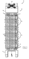
Figure 1 is a side elevation view of a pressurized water reactor nuclear fuel assembly having spacer grids made of interlaced strips; -
Figure 2 is a partial sectional side view of a boiling water reactor nuclear fuel assembly having spacer grids made of interlaced strips; -
Figure 3 is a partial top view of a spacer grid according to the invention; -
Figure 4 is a partial front view of a strip of the spacer grid ofFigure 3 ; -
Figure 5 is a front view of a spring and an associated motion limiter of the strip ofFigure 4 ; -
Figure 6 is a sectional view of the spring and the motion limiter along VI-VI onFigure 5 ; -
Figure 7 is a partial sectional view of a cell of the spacer grid with a fuel rod extending through the cell; -
Figures 8 and 9 are views corresponding respectively toFigures 5 and 6 illustrating another embodiment of the invention; and -
Figure 10 is a front view of a strip illustrating another embodiment of the invention; and -
Figure 11 is a front view of a strip of still another embodiment of the invention. - The
nuclear fuel assembly 2 for a pressurized water reactor (PWR) illustrated onFigure 1 comprises a bundle ofnuclear fuel rods 4 and an armature 6 for supporting thefuel rods 4. ThePWR fuel assembly 2 is elongated along an assembly axis L extending vertically when thefuel assembly 2 is disposed inside a nuclear reactor. - The armature 6 comprises a
lower nozzle 8, anupper nozzle 10, a plurality of guide-tubes 12 and a plurality ofspacer grids 14. - The guide-
tubes 12 extend parallel to assembly axis L and connect thelower nozzle 8 to theupper nozzle 10 and maintain a predetermined spacing along assembly axis L between thenozzles tube 12 opens upwards through theupper nozzle 10 for allowing insertion of a control rod into the guide-tube 12. - The
nuclear fuel assembly 2 for a boiling water reactor (BWR) illustrated onFigure 2 is also elongated along an assembly axis L extending vertically when thefuel assembly 2 is disposed inside a nuclear reactor. - The
BWR fuel assembly 2 comprises a bundle ofnuclear fuel rods 4, an armature for maintaining thefuel rods 4 and atubular fuel channel 15 surrounding the bundle offuel rods 4. The armature typically comprises a lower nozzle and an upper nozzle spaced along assembly axis L, at least onewater channel 13 arranged within the bundle offuel rods 4 and a plurality ofspacer grids 14 distributed along the bundle offuel rods 4. - The
fuel rods 4, thewater channel 13 and thefuel channel 15 extend between the lower nozzle and the upper nozzle, with thewater channel 13 and thefuel channel 15 connecting the lower nozzle and the upper nozzle. - The
water channel 13 extends parallel to thefuel rods 4. Thewater channel 13 is arranged for channeling a coolant/moderator flow separately from the bundle offuel rods 4. - The
fuel channel 15 extends parallel to thefuel rods 4. Thefuel channel 15 encases the bundle offuel rods 4 and thewater channel 13. Thefuel channel 15 is arranged for channeling a coolant/moderator flow between and about thefuel rods 4. - The PWR and
BWR spacer grids 14 are distributed in spaced relationship along thefuel rods 4. - Each
spacer grid 14 extends transversely to the assembly axis L. - Each
fuel rod 4 comprises a tubular cladding, pellets of nuclear fuel stacked inside the cladding and caps closing the ends of the cladding. Eachfuel rod 4 extends parallel to assembly axis L through thespacer grids 14 with being supported transversely and longitudinally relative to assembly axis L by thespacer grids 14. - In operation, the
fuel assembly 2 is placed in a nuclear reactor with thelower nozzle 8 resting on a bottom plate of the reactor and the assembly axis L being substantially vertical. A coolant flows upwardly along thefuel assembly 2 with flowing between thefuel rods 4 and through thenozzles spacer grids 14 as illustrated by arrows F onFigures 1 and2 . - The
spacer grids 14 may be similar to each other and onespacer grid 14 according to the invention will be further described with reference toFigures 3 - 7 . - As illustrated on
Figure 3 , thespacer grid 14 comprises a plurality of interlacedmetallic strips 16 defining a lattice ofcells 18 each for receiving onefuel rod 4, only afew cells 18 being illustrated onFigure 3 . - In a known manner, in the case of a spacer grid for a PWR fuel assembly, the interlaced
strips 16 also define a plurality of cells for receiving PWR guide-tubes 12, thespacer grid 14 being secured to the guide-tubes 12, e.g. by welding. Similarly, in the case of a spacer grid for a BWR fuel assembly, the at least oneBWR water channel 13 typically replaces one orseveral fuel rods 4 in the lattice, the interlaced strips define an aperture for receiving thewater channel 13 and thespacer grid 14 is secured to thewater channel 13, e.g. by welding. - Only
cells 18 for receivingfuel rods 4 are illustrated onFigure 3 and in the following, the term "cell" refer to thecells 18 for receivingfuel rods 4. - Each
cell 18 is tubular and extends along a cell axis A. The cell axis A is to be parallel to the assembly axis L (perpendicular toFigure 3 ) when thespacer grid 14 is assembled in the fuel assembly 2 (Figures 1 and2 ). The cell axes A of thedifferent cells 18 are parallel. Eachcell 18 is delimited by fourwall portions 20 of two pairs ofintersecting strips 16, thestrips 16 of each pair extending parallel to one another. - One
wall portion 20 of each pair ofopposite wall portions 20 delimiting acell 18 has anelastic spring 22 formed in thewall portion 20 and protruding in a free state towards the center of thecell 18, and theother wall portion 20 of each pair ofopposite wall portions 20 has arigid dimple 24 formed in thewall portion 20 and protruding towards the center of thecell 18. - The
springs 22 anddimples 24 provided on thewall portions 20 of eachcell 18 are arranged such that afuel rod 4 extending through thecell 18 is biased transversely by thesprings 22 against thedimples 24 to support thefuel rod 4 transversely and longitudinally relative to the cell axis A. - Each
wall portion 20 delimiting two adjacent cells 18 (one on each side of the strip 16) has aspring 22 protruding on a face of thewall portion 20 in one of thecells 18 and adimple 24 protruding on the opposite face of thewall portion 20 in theother cell 18. Eachwall portion 20 delimiting only onecell 18 has either aspring 22 or adimple 24. -
Figure 4 illustrates a plurality of thewall portions 20 of astrip 16, each of thesewall portions 20 being adapted to delimit twocells 18, one on each side of thestrip 16. - In operation, the coolant flows upwardly through each
cell 18 in the flow direction F represented onFigure 4 from an upstreamlower edge 26 to a downstreamupper edge 28 of thestrip 16. The flow direction F is parallel to the cell axis A. - Each
wall portion 20 extends from thelower edge 26 to theupper edge 28. Thewall portions 20 are separated byslits 30 provided on thelower edge 26 and extending substantially to the half-height of thestrip 16 for engagement with a series ofcorresponding slits 30 provided on theupper edge 28 and extending substantially to the half-height of anintersecting strip 16. - The
strip 16 optionally comprisesfins 32 protruding upwardly from theupper edge 28, eachfin 32 being inclined relative to the cell axis A for imparting helical motion to the coolant fluid flowing through thecells 18 and enhancing heat exchange between the coolant and thefuel rods 4. - The
strip 16 comprises on each of the illustrated wall portions 20 aspring 22, adimple 24 and amotion limiter 34 each formed in thestrip 16 and thus being integrally one-piece with thestrip 16. - The
spring 22 and themotion limiter 34 provided on eachwall portion 20 protrude on the same face of thestrip 16, whereas thedimple 24 protrudes on the opposite face of thestrip 16. - The
dimples 24 are alternately disposed below and above thesprings 22 on theadjacent wall portions 20. Interlaced strips 16 thus can be arranged such that aspring 22 provided on awall portion 20 of astrip 16 delimiting acell 18 faces adimple 24 provided on theopposite wall portion 20 of anotherstrip 16 delimiting thecell 18. - The
springs 22 of thestrip 16 are identical and onespring 22 is further described with reference toFigures 5 - 7 . - The
spring 22 illustrated onFigure 5 comprises a flexiblecantilevered tab 36 and acontact portion 38 cut out in thestrip 16. - The
tab 36 is delimited in thestrip 16 by an elongatedcurved slot 40 of closed contour. Thetab 36 is delimited between theslot 40 and theconnection line 46 joining the opposed ends 48 of theslot 40. The ends 48 are preferably circular and enlarged to limit mechanical local peak stresses. Theline 46 is perpendicular to the cell axis A. Thetab 36 is connected to thewall portion 20 along theline 46. - The
tab 36 extends downwardly in cantilevered fashion towards the upstreamlower edge 26 and has anupper base 42 connected to thewall portion 20 and a lowerfree tip 44. Thetab 36 is converging towards thefree tip 44. Theslot 40 is generally U-shape with diverging branches (or V-shape with a rounded tip). - In a free state of the
spring 22, thetab 36 is inclined relative to thewall portion 20 and extends downwardly and away from thewall portion 20 towards the center of thecell 18 delimited by thewall portion 20. Thetab 36 is elastically flexible by elastic deformation of thetab 36 with rotation of thetab 36 around a rotation axis substantially coinciding with theline 46. The flexibility of the tab can be adjusted by adjusting the diameter of theends 48 of theslot 40. - The
contact portion 38 is formed exclusively in thetab 36 and protrudes from thetab 36 opposite thewall portion 20 and towards the center of acell 18 delimited by thewall portion 20. Thecontact portion 38 is integrally one-piece with thetab 36. - According to the embodiment illustrated on
Figures 4-6 , thecontact portion 38 is provided in the form of an arched bridge cut out in thetab 36. Thecontact portion 38 is elongated in the direction of the cell axis A, the two ends of thecontact portion 38 connected to thetab 36 being aligned in the direction of the cell axis A. Thecontact portion 38 is formed as a lancing delimited between twoopenings 52 extending substantially parallel to each other in the direction of the cell axis A. - The
motion limiter 34 associated to thespring 22 is formed in thestrip 16 at a distance from thespring 22 and protrudes from thewall portion 20 on the same side than the correspondingspring 22. Themotion limiter 34 is a bulge of curved perimeter formed in thestrip 16, for instance of circular perimeter as illustrated onFigure 5 with a risenportion 56 and an apex 62. Themotion limiter 34 is disposed below or above the corresponding spring 22 (Figure 3 ). - As illustrated on
Figure 7 , thecontact portion 38 contacts the outer surface of afuel rod 4 extending through acell 18 delimited by thewall portion 20 with thetab 36 being elastically deformed towards thewall portion 20. Thespring 22 thus biases thefuel rod 4 away from the wall portion 20 (toward the right onFigure 7 ) in contact with adimple 24 provided on theopposite wall portion 20 delimiting thecell 18. - In this configuration, the
free tip 44 of thetab 36 extends substantially in the plane of thewall portion 20 and the height H of thecontact portion 38 relative to thewall portion 20 is superior to the height h of the apex 62 of themotion limiter 34. There is a gap D between the apex 62 and the outer surface of thefuel rod 4. - In operation, the coolant flows through the
cell 18 and around thefuel rod 4 upwardly at high speed in the flow direction F parallel to the cell axis A. This causes transverse vibration of thefuel rod 4 inside thecell 18. Transverse vibrations may also occur during transportation from manufacturing plant to power plant and during handling of thefuel assembly 2. - The
motion limiter 34 is rigid and limits movements of afuel rod 4 towards thewall portion 20 against the action of thespring 22. Themotion limiter 34 thus avoids overstress of thespring 22 and namely plastic deformation thereof. - The
spring 22 formed in thestrip 16 with a flexiblecantilevered tab 36 and arigid contact portion 38 enables to bias thefuel rod 4 with an appropriate transverse force while limiting the flow resistance. Thetab 36 furnishes the biasing force when thefree tip 44 of thetab 36 is retracted in the plane (or nearly) of thewall portion 20; in this position only thecontact portion 38 protrudes from thewall portion 20. - The
contact portion 38 being elongated in the flow direction F enables to further limit the flow resistance and to provide an elongated contact zone with thefuel rod 4 for limiting fretting risks. - The
spring 22 including thetab 36 and thecontact portion 38 is obtainable in a single stamping operation easily and at low cost. - The alternative embodiment of
Figures 8 and 9 differs from that ofFigure 5 and 6 by the feature that thecontact portion 38 is formed partially in thetab 36 and partially in thewall portion 20. Thecontact portion 38 is more elongated and steps over theline 46 joining theends 48 of theslot 40 delimiting thetab 36. - This increases the stiffness of the
spring 22 as biasing thespring 22 causes simultaneous deformation of theupper base 42 of thetab 36 and of the upper end of thecontact portion 38 about two parallel but different axes. - In the alternative embodiment of
Figure 10 , themotion limiter 34 is a bulge having an elliptical perimeter. Themotion limiter 34 is elongated transversely to the flow direction F. Eachmotion limiter 34 is located above the correspondingspring 22 in line with thespring 22 in the flow direction. Eachmotion limiter 34 is located adjacent the base of thespring tab 36. Preferably, themotion limiter 34 is tangent to theconnection line 46. - The
contact portion 38 is provided in the form of a closed bulge of curved perimeter. As illustrated onFigure 10 , the perimeter is advantageously an elliptical perimeter preferably elongated in the flow direction F. - The
dimples 24 are also provided in the form of bulges of elliptical perimeter elongated in the flow direction. - In an alternative embodiment, the
motion limiter 34 ofFigure 10 is combined with aspring 22 having a bridge-like contact portion 38 cut in the spring as inFigures 4 - 6 . In another alternative embodiment, themotion limiter 34 of circular perimeter ofFigures 4 - 6 is combined with the contact portion ofFigure 10 in the form of a closed bulge, namely of elliptical perimeter. - In the different embodiments, the
motion limiter 34 and thespring 22 provided in line, one upstream the other in the flow direction F, reduce flow resistance of thestrip 16. - The
motion limiter 34 located above thespring 22 adjacent theconnection line 46 stiffens thespring element 22 and lead to less local peak stresses at theends 48 of theslot 40. These effects are even increased with themotion limiter 34 of elliptical perimeter ofFigure 10 . - In the alternative embodiment of
Figure 11 , the upstreamlower edge 26 of thestrip 16 is zigzag-shaped such that it is low at the center of eachwall portion 20 and high at the junction between thewall portions 20 where interlaced strips 16 intersect each other. - As a result, a
spacer grid 14 may be formed with interlacedstrips 16 crossing at cross points 66 at a level higher than thelower points 64, whereby debris possibly present in the coolant fluid are guided transversely towards the cross points 66 at corners of the square shapedcells 18 where the space between the inner surface of thecells 18 and thefuel rods 4 is larger. The debris are thus prevented from damaging thefuel rods 4. - In an alternative embodiment, the
lower edge 26 of thestrip 16 is zigzag-shaped such that the upstreamlower edge 26 is alternatively at a high level and at a low level at the junction between thewall portions 20. - As a result, the interlaced strips 16 may be assembled to provide
cross points 66 at a high level and crosspoints 66 at a low level arranged in staggered rows, with the same benefit. - The
lower edge 26 may present a wave shape instead of a zigzag shape. - The invention is applicable to spacer grids for a PWR (Pressurized Water Reactor) fuel assembly or to spacer grids for a BWR (Boiling Water Reactor) fuel assembly as illustrated and also to spacer grids for a VVER (Water-Water Energetic Reactor) fuel assembly.
Claims (19)
- A strip (16) for a nuclear fuel assembly spacer grid (14) comprising interlaced strips defining a lattice of cells (18) for receiving fuel rods (4) and allowing flow of a coolant in a flow direction (F), the strip (16) being of the type comprising a wall portion (20) for delimiting a cell (18), a spring (22) formed in the strip (16) and provided on the wall portion (20) for biasing the fuel rod (4) extending through the cell (18) away from the wall portion (20), and a motion limiter (34) formed in the strip (16) on the wall portion (20) to limit motion of the fuel rod (4) received in the cell (18) towards the wall portion (20) against action of the spring (22), the spring (22) comprising a cantilevered tab (36) formed in the strip (16) and a contact portion (38) formed at least partially in the tab (36) and protruding from the tab (36) for contacting the fuel rod (4) received in the cell (18), a connection line (46) between the tab (36) and the wall portion (20) extending perpendicularly to the flow direction (F), the motion limiter (34) being located in line with the spring (22) in the flow direction (F), upstream or downstream the spring (22).
- Strip according to claim 1, wherein in a free state of the spring (22), the tab (36) is inclined relative to the wall portion (20).
- Strip according to claim 1 or 2, wherein the contact portion (38) is formed exclusively in the tab (36).
- Strip according to claim 1 or 2, wherein the contact portion (38) is formed in the tab (36) and in the wall portion (20), the contact portion (38) stepping over the connection line (46).
- Strip according to any preceding claim, wherein the contact portion (38) is in the form of an arched bridge or a bulge.
- Strip according to claim 4, wherein the contact portion (38) is in the form of an arched bridge having an end connected to the tab (36) and an end connected to the wall portion (20).
- Strip according to any of claims 1 - 5, wherein the contact portion (38) is of curved perimeter, namely of elliptical perimeter.
- Strip according to any preceding claim, wherein the contact portion (38) is elongated in the flow direction (F).
- Strip according to any preceding claim, wherein the tab (36) extends downwardly in cantilevered fashion towards an upstream lower edge (26) of the strip (16).
- Strip according to any preceding claim, wherein the tab (36) has a base (42) connected to the wall portion (20) and a free tip (44), the tab (36) converging towards the free tip (44).
- Strip according to any preceding claim, wherein the tab (36) is delimited by an elongated curved slot (40), the connection line (46) joining the two opposite ends (48) of the slot (40).
- Strip according to claim 11, wherein the slot (40) is U-shaped with branches diverging one from the other.
- Strip according to any preceding claim, wherein the motion limiter (34) is elongated in the flow direction (F) or transverse to the flow direction (F).
- Strip according to any preceding claim, wherein the motion limiter (34) is a bulge.
- Strip according to any preceding claim, wherein the motion limiter (34) is of curved perimeter, namely of circular or elliptical perimeter.
- Strip according to any preceding claim, wherein the motion limiter (34) is adjacent, namely tangent to the connection line (46).
- Strip according to any preceding claim, wherein, in a configuration where the free tip (44) of the tab (36) extends substantially in the plane of the wall portion (20), the height (H) of the contact portion (38) relative to the wall portion (20) is superior to the height (h) of the apex (62) of the motion limiter (34).
- A spacer grid (14) comprising interlaced strips defining a lattice of cells (18) for receiving fuel rods (4) and allowing flow of a coolant axially upwardly through the spacer grid (14), at least one of the interlaced strips being a strip (16) as defined in any preceding claim.
- A nuclear fuel assembly (2) comprising a bundle of fuel rods (4) and an armature (6) for supporting the fuel rods (4), the armature (6) comprising at least one spacer grid (14) as defined in claim 20.
Priority Applications (1)
| Application Number | Priority Date | Filing Date | Title |
|---|---|---|---|
| EP15161691.9A EP2913824B1 (en) | 2011-05-20 | 2012-05-18 | Strip for a nuclear fuel assembly spacer grid |
Applications Claiming Priority (3)
| Application Number | Priority Date | Filing Date | Title |
|---|---|---|---|
| EP11305628A EP2525366A1 (en) | 2011-05-20 | 2011-05-20 | Strip for a nuclear fuel assembly spacer grid |
| EP12723162.9A EP2710604B1 (en) | 2011-05-20 | 2012-05-18 | Strip for a nuclear fuel assembly spacer grid |
| EP15161691.9A EP2913824B1 (en) | 2011-05-20 | 2012-05-18 | Strip for a nuclear fuel assembly spacer grid |
Related Parent Applications (2)
| Application Number | Title | Priority Date | Filing Date |
|---|---|---|---|
| EP12723162.9A Division-Into EP2710604B1 (en) | 2011-05-20 | 2012-05-18 | Strip for a nuclear fuel assembly spacer grid |
| EP12723162.9A Division EP2710604B1 (en) | 2011-05-20 | 2012-05-18 | Strip for a nuclear fuel assembly spacer grid |
Publications (2)
| Publication Number | Publication Date |
|---|---|
| EP2913824A1 true EP2913824A1 (en) | 2015-09-02 |
| EP2913824B1 EP2913824B1 (en) | 2017-02-01 |
Family
ID=46148858
Family Applications (3)
| Application Number | Title | Priority Date | Filing Date |
|---|---|---|---|
| EP11305628A Withdrawn EP2525366A1 (en) | 2011-05-20 | 2011-05-20 | Strip for a nuclear fuel assembly spacer grid |
| EP12723162.9A Active EP2710604B1 (en) | 2011-05-20 | 2012-05-18 | Strip for a nuclear fuel assembly spacer grid |
| EP15161691.9A Active EP2913824B1 (en) | 2011-05-20 | 2012-05-18 | Strip for a nuclear fuel assembly spacer grid |
Family Applications Before (2)
| Application Number | Title | Priority Date | Filing Date |
|---|---|---|---|
| EP11305628A Withdrawn EP2525366A1 (en) | 2011-05-20 | 2011-05-20 | Strip for a nuclear fuel assembly spacer grid |
| EP12723162.9A Active EP2710604B1 (en) | 2011-05-20 | 2012-05-18 | Strip for a nuclear fuel assembly spacer grid |
Country Status (7)
| Country | Link |
|---|---|
| US (1) | US9953730B2 (en) |
| EP (3) | EP2525366A1 (en) |
| JP (2) | JP6296976B2 (en) |
| KR (1) | KR20140033435A (en) |
| CN (1) | CN103563005B (en) |
| ES (2) | ES2622389T3 (en) |
| WO (1) | WO2012160003A1 (en) |
Families Citing this family (5)
| Publication number | Priority date | Publication date | Assignee | Title |
|---|---|---|---|---|
| US9881701B2 (en) * | 2012-04-17 | 2018-01-30 | Bwxt Mpower, Inc. | Spacer grids with springs having improved robustness |
| CN104318962B (en) * | 2014-10-16 | 2017-07-14 | 岭澳核电有限公司 | Positioning grid frame with streamline low-pressure-drop flow channels and fuel assembly |
| CN105869681B (en) * | 2016-05-26 | 2018-03-20 | 中广核研究院有限公司 | Fuel assembly and its without outer band grid spacer and band |
| CN107230502A (en) * | 2017-06-09 | 2017-10-03 | 岭东核电有限公司 | Fuel assembly and its screen work and support insert |
| EP4016547A1 (en) * | 2020-12-21 | 2022-06-22 | Framatome | Spacer grid element of a nuclear fuel assembly spacer grid, spacer grids and nuclear fuel assembly |
Citations (5)
| Publication number | Priority date | Publication date | Assignee | Title |
|---|---|---|---|---|
| US3844887A (en) * | 1968-09-12 | 1974-10-29 | Westinghouse Electric Corp | Nuclear reactor fuel assembly |
| US4058436A (en) * | 1975-12-05 | 1977-11-15 | Combustion Engineering Inc. | Nuclear reactor seismic fuel assembly grid |
| US4163690A (en) * | 1977-01-07 | 1979-08-07 | The Babcock & Wilcox Company | Nuclear reactor fuel assembly spacer grid |
| GB2181292A (en) * | 1985-10-04 | 1987-04-15 | Westinghouse Electric Corp | Nuclear reactor spacer grid and ductless core component |
| US4879090A (en) | 1987-08-24 | 1989-11-07 | Combustion Engineering, Inc. | Split vaned nuclear fuel assembly grid |
Family Cites Families (24)
| Publication number | Priority date | Publication date | Assignee | Title |
|---|---|---|---|---|
| JPS554533A (en) * | 1978-06-27 | 1980-01-14 | Tokyo Shibaura Electric Co | Grid spacer |
| FR2465297A1 (en) * | 1979-09-07 | 1981-03-20 | Commissariat Energie Atomique | SPACING GRID FOR COMBUSTIBLE ELEMENTS OF NUCLEAR REACTORS |
| US4426355A (en) * | 1982-01-04 | 1984-01-17 | Combustion Engineering, Inc. | Spacer grid for nuclear fuel assembly |
| JPS61108997U (en) * | 1984-12-21 | 1986-07-10 | ||
| US4702881A (en) | 1985-04-02 | 1987-10-27 | Westinghouse Electric Corp. | Nuclear reactor spacer grid |
| JPS62148891A (en) | 1985-12-24 | 1987-07-02 | 株式会社日立製作所 | electromagnetic flow diode |
| FR2616577B1 (en) | 1987-06-09 | 1991-02-15 | Framatome Sa | SPACER GRILLE FOR A FUEL ASSEMBLY OF A LIGHT WATER NUCLEAR REACTOR |
| JPH01173898A (en) | 1987-09-10 | 1989-07-10 | Mitsubishi Nuclear Fuel Co Ltd | Supporting grid of nuclear reactor fuel assembly |
| JPH067190B2 (en) | 1988-03-24 | 1994-01-26 | 三菱原子燃料株式会社 | Support grid |
| JPH0221597A (en) * | 1988-07-11 | 1990-01-24 | Hitachi Medical Corp | X-ray device |
| JPH0221597U (en) * | 1988-07-29 | 1990-02-13 | ||
| JPH02257092A (en) | 1989-03-30 | 1990-10-17 | Nuclear Fuel Ind Ltd | Ring element type fuel spacer |
| FR2666678B1 (en) | 1990-07-24 | 1993-07-30 | Framatome Sa | GRILLE WITH MIXING FINS FOR NUCLEAR FUEL ASSEMBLY. |
| SE468110B (en) * | 1991-03-13 | 1992-11-02 | Asea Atom Ab | DISTRIBUTOR FOR CONTAINING BRAINSLET STARS IN A CORE REACTOR'S BRAINSLE PATTERN |
| US5331678A (en) | 1993-04-27 | 1994-07-19 | Combustion Engineering, Inc. | Spacer grid rod support system |
| FR2736190B1 (en) * | 1995-06-29 | 1997-10-10 | Framatome Sa | GRID SPACER OF A FUEL ASSEMBLY FOR A NUCLEAR REACTOR AND FUEL ASSEMBLY |
| US6526116B1 (en) | 1997-07-02 | 2003-02-25 | Westinghouse Electric Company Llc | Nuclear fuel assembly with hydraulically balanced mixing vanes |
| FR2766003B1 (en) * | 1997-07-11 | 1999-12-03 | Framatome Sa | GRID FOR NUCLEAR FUEL ASSEMBLY AND PLATE FOR SUCH A GRID |
| KR100330358B1 (en) | 1999-07-29 | 2002-04-01 | 장인순 | Spacer grid with multi-spring and embossed vane for PWR fuel assembly |
| KR100432581B1 (en) | 2001-07-10 | 2004-05-24 | 한국수력원자력 주식회사 | Spacer Grid for Uniform Conformal Contact with Fuel Rod and for Extending the Elastic Range of the Grid Spring |
| US6819733B2 (en) | 2002-05-15 | 2004-11-16 | Westinghouse Electric Company Llc | Fuel assembly and associated grid for nuclear reactor |
| KR20070102001A (en) | 2006-04-13 | 2007-10-18 | 한국원자력연구원 | Support grid spring increases fuel rod and conformal contact area |
| FR2910687B1 (en) * | 2006-12-26 | 2016-08-26 | Areva Np | HORSE-SIDED SUPPORT SUPPORT GRILLE AND CORRESPONDING NUCLEAR FUEL ASSEMBLY. |
| EP2525363A1 (en) | 2011-05-20 | 2012-11-21 | Areva NP | Strip for a nuclear fuel assembly spacer grid |
-
2011
- 2011-05-20 EP EP11305628A patent/EP2525366A1/en not_active Withdrawn
-
2012
- 2012-05-18 ES ES15161691.9T patent/ES2622389T3/en active Active
- 2012-05-18 JP JP2014510830A patent/JP6296976B2/en not_active Expired - Fee Related
- 2012-05-18 EP EP12723162.9A patent/EP2710604B1/en active Active
- 2012-05-18 CN CN201280024558.2A patent/CN103563005B/en not_active Expired - Fee Related
- 2012-05-18 WO PCT/EP2012/059306 patent/WO2012160003A1/en not_active Ceased
- 2012-05-18 US US13/822,510 patent/US9953730B2/en active Active
- 2012-05-18 KR KR1020137033628A patent/KR20140033435A/en not_active Withdrawn
- 2012-05-18 ES ES12723162.9T patent/ES2548840T3/en active Active
- 2012-05-18 EP EP15161691.9A patent/EP2913824B1/en active Active
-
2017
- 2017-12-01 JP JP2017231539A patent/JP6448750B2/en active Active
Patent Citations (5)
| Publication number | Priority date | Publication date | Assignee | Title |
|---|---|---|---|---|
| US3844887A (en) * | 1968-09-12 | 1974-10-29 | Westinghouse Electric Corp | Nuclear reactor fuel assembly |
| US4058436A (en) * | 1975-12-05 | 1977-11-15 | Combustion Engineering Inc. | Nuclear reactor seismic fuel assembly grid |
| US4163690A (en) * | 1977-01-07 | 1979-08-07 | The Babcock & Wilcox Company | Nuclear reactor fuel assembly spacer grid |
| GB2181292A (en) * | 1985-10-04 | 1987-04-15 | Westinghouse Electric Corp | Nuclear reactor spacer grid and ductless core component |
| US4879090A (en) | 1987-08-24 | 1989-11-07 | Combustion Engineering, Inc. | Split vaned nuclear fuel assembly grid |
Also Published As
| Publication number | Publication date |
|---|---|
| JP6296976B2 (en) | 2018-03-20 |
| ES2622389T3 (en) | 2017-07-06 |
| WO2012160003A1 (en) | 2012-11-29 |
| JP6448750B2 (en) | 2019-01-09 |
| KR20140033435A (en) | 2014-03-18 |
| EP2710604B1 (en) | 2015-07-01 |
| US9953730B2 (en) | 2018-04-24 |
| CN103563005A (en) | 2014-02-05 |
| US20140056398A1 (en) | 2014-02-27 |
| CN103563005B (en) | 2016-06-01 |
| EP2913824B1 (en) | 2017-02-01 |
| EP2710604A1 (en) | 2014-03-26 |
| JP2014519033A (en) | 2014-08-07 |
| JP2018028557A (en) | 2018-02-22 |
| EP2525366A1 (en) | 2012-11-21 |
| ES2548840T3 (en) | 2015-10-21 |
Similar Documents
| Publication | Publication Date | Title |
|---|---|---|
| EP2710600B1 (en) | Strip for a nuclear fuel assembly spacer grid | |
| EP1868208B1 (en) | Nuclear fuel rod spacer assembly with debris guide | |
| EP2913824B1 (en) | Strip for a nuclear fuel assembly spacer grid | |
| US6421407B1 (en) | Nuclear fuel spacer grid with dipper vanes | |
| KR20010011647A (en) | Spacer grid with multi-spring and embossed vane for PWR fuel assembly | |
| EP2710605B1 (en) | Nuclear fuel assembly spacer grid and corresponding nuclear fuel assembly | |
| EP1416500B1 (en) | Side-slotted nozzle type double sheet spacer grid for nuclear fuel assemblies | |
| KR100627544B1 (en) | A nuclear fuel assembly grid with diagonal fuel retaining springs | |
| US9196386B2 (en) | Spacer grid for nuclear fuel assembly for reducing high frequency vibration | |
| TW201312588A (en) | Strip for a nuclear fuel assembly spacer grid | |
| US6272197B1 (en) | Coolant mixing grid for nuclear fuel assembly | |
| US20240428959A1 (en) | Nuclear reactor fuel assembly spacer grid |
Legal Events
| Date | Code | Title | Description |
|---|---|---|---|
| PUAI | Public reference made under article 153(3) epc to a published international application that has entered the european phase |
Free format text: ORIGINAL CODE: 0009012 |
|
| 17P | Request for examination filed |
Effective date: 20150330 |
|
| AC | Divisional application: reference to earlier application |
Ref document number: 2710604 Country of ref document: EP Kind code of ref document: P |
|
| AK | Designated contracting states |
Kind code of ref document: A1 Designated state(s): AL AT BE BG CH CY CZ DE DK EE ES FI FR GB GR HR HU IE IS IT LI LT LU LV MC MK MT NL NO PL PT RO RS SE SI SK SM TR |
|
| GRAP | Despatch of communication of intention to grant a patent |
Free format text: ORIGINAL CODE: EPIDOSNIGR1 |
|
| INTG | Intention to grant announced |
Effective date: 20160819 |
|
| GRAJ | Information related to disapproval of communication of intention to grant by the applicant or resumption of examination proceedings by the epo deleted |
Free format text: ORIGINAL CODE: EPIDOSDIGR1 |
|
| GRAR | Information related to intention to grant a patent recorded |
Free format text: ORIGINAL CODE: EPIDOSNIGR71 |
|
| GRAS | Grant fee paid |
Free format text: ORIGINAL CODE: EPIDOSNIGR3 |
|
| GRAA | (expected) grant |
Free format text: ORIGINAL CODE: 0009210 |
|
| INTC | Intention to grant announced (deleted) | ||
| RIN1 | Information on inventor provided before grant (corrected) |
Inventor name: BISHOP, WILLIAM D. Inventor name: LIEBLER, MICHAEL Inventor name: DRESSEL, BERND Inventor name: MORRIS, JEFFREY C. Inventor name: ELLIOTT, KEVIN |
|
| INTG | Intention to grant announced |
Effective date: 20161219 |
|
| AC | Divisional application: reference to earlier application |
Ref document number: 2710604 Country of ref document: EP Kind code of ref document: P |
|
| AK | Designated contracting states |
Kind code of ref document: B1 Designated state(s): AL AT BE BG CH CY CZ DE DK EE ES FI FR GB GR HR HU IE IS IT LI LT LU LV MC MK MT NL NO PL PT RO RS SE SI SK SM TR |
|
| REG | Reference to a national code |
Ref country code: GB Ref legal event code: FG4D |
|
| REG | Reference to a national code |
Ref country code: CH Ref legal event code: EP Ref country code: AT Ref legal event code: REF Ref document number: 866144 Country of ref document: AT Kind code of ref document: T Effective date: 20170215 |
|
| REG | Reference to a national code |
Ref country code: IE Ref legal event code: FG4D |
|
| REG | Reference to a national code |
Ref country code: DE Ref legal event code: R096 Ref document number: 602012028510 Country of ref document: DE |
|
| REG | Reference to a national code |
Ref country code: SE Ref legal event code: TRGR |
|
| REG | Reference to a national code |
Ref country code: NL Ref legal event code: MP Effective date: 20170201 |
|
| REG | Reference to a national code |
Ref country code: LT Ref legal event code: MG4D |
|
| REG | Reference to a national code |
Ref country code: AT Ref legal event code: MK05 Ref document number: 866144 Country of ref document: AT Kind code of ref document: T Effective date: 20170201 |
|
| REG | Reference to a national code |
Ref country code: ES Ref legal event code: FG2A Ref document number: 2622389 Country of ref document: ES Kind code of ref document: T3 Effective date: 20170706 |
|
| PG25 | Lapsed in a contracting state [announced via postgrant information from national office to epo] |
Ref country code: IS Free format text: LAPSE BECAUSE OF FAILURE TO SUBMIT A TRANSLATION OF THE DESCRIPTION OR TO PAY THE FEE WITHIN THE PRESCRIBED TIME-LIMIT Effective date: 20170601 Ref country code: HR Free format text: LAPSE BECAUSE OF FAILURE TO SUBMIT A TRANSLATION OF THE DESCRIPTION OR TO PAY THE FEE WITHIN THE PRESCRIBED TIME-LIMIT Effective date: 20170201 Ref country code: GR Free format text: LAPSE BECAUSE OF FAILURE TO SUBMIT A TRANSLATION OF THE DESCRIPTION OR TO PAY THE FEE WITHIN THE PRESCRIBED TIME-LIMIT Effective date: 20170502 Ref country code: NO Free format text: LAPSE BECAUSE OF FAILURE TO SUBMIT A TRANSLATION OF THE DESCRIPTION OR TO PAY THE FEE WITHIN THE PRESCRIBED TIME-LIMIT Effective date: 20170501 Ref country code: FI Free format text: LAPSE BECAUSE OF FAILURE TO SUBMIT A TRANSLATION OF THE DESCRIPTION OR TO PAY THE FEE WITHIN THE PRESCRIBED TIME-LIMIT Effective date: 20170201 Ref country code: LT Free format text: LAPSE BECAUSE OF FAILURE TO SUBMIT A TRANSLATION OF THE DESCRIPTION OR TO PAY THE FEE WITHIN THE PRESCRIBED TIME-LIMIT Effective date: 20170201 |
|
| PG25 | Lapsed in a contracting state [announced via postgrant information from national office to epo] |
Ref country code: PL Free format text: LAPSE BECAUSE OF FAILURE TO SUBMIT A TRANSLATION OF THE DESCRIPTION OR TO PAY THE FEE WITHIN THE PRESCRIBED TIME-LIMIT Effective date: 20170201 Ref country code: RS Free format text: LAPSE BECAUSE OF FAILURE TO SUBMIT A TRANSLATION OF THE DESCRIPTION OR TO PAY THE FEE WITHIN THE PRESCRIBED TIME-LIMIT Effective date: 20170201 Ref country code: AT Free format text: LAPSE BECAUSE OF FAILURE TO SUBMIT A TRANSLATION OF THE DESCRIPTION OR TO PAY THE FEE WITHIN THE PRESCRIBED TIME-LIMIT Effective date: 20170201 Ref country code: LU Free format text: LAPSE BECAUSE OF NON-PAYMENT OF DUE FEES Effective date: 20170531 Ref country code: PT Free format text: LAPSE BECAUSE OF FAILURE TO SUBMIT A TRANSLATION OF THE DESCRIPTION OR TO PAY THE FEE WITHIN THE PRESCRIBED TIME-LIMIT Effective date: 20170601 Ref country code: BG Free format text: LAPSE BECAUSE OF FAILURE TO SUBMIT A TRANSLATION OF THE DESCRIPTION OR TO PAY THE FEE WITHIN THE PRESCRIBED TIME-LIMIT Effective date: 20170501 Ref country code: LV Free format text: LAPSE BECAUSE OF FAILURE TO SUBMIT A TRANSLATION OF THE DESCRIPTION OR TO PAY THE FEE WITHIN THE PRESCRIBED TIME-LIMIT Effective date: 20170201 Ref country code: NL Free format text: LAPSE BECAUSE OF FAILURE TO SUBMIT A TRANSLATION OF THE DESCRIPTION OR TO PAY THE FEE WITHIN THE PRESCRIBED TIME-LIMIT Effective date: 20170201 |
|
| PG25 | Lapsed in a contracting state [announced via postgrant information from national office to epo] |
Ref country code: IT Free format text: LAPSE BECAUSE OF FAILURE TO SUBMIT A TRANSLATION OF THE DESCRIPTION OR TO PAY THE FEE WITHIN THE PRESCRIBED TIME-LIMIT Effective date: 20170201 Ref country code: RO Free format text: LAPSE BECAUSE OF FAILURE TO SUBMIT A TRANSLATION OF THE DESCRIPTION OR TO PAY THE FEE WITHIN THE PRESCRIBED TIME-LIMIT Effective date: 20170201 Ref country code: EE Free format text: LAPSE BECAUSE OF FAILURE TO SUBMIT A TRANSLATION OF THE DESCRIPTION OR TO PAY THE FEE WITHIN THE PRESCRIBED TIME-LIMIT Effective date: 20170201 Ref country code: CZ Free format text: LAPSE BECAUSE OF FAILURE TO SUBMIT A TRANSLATION OF THE DESCRIPTION OR TO PAY THE FEE WITHIN THE PRESCRIBED TIME-LIMIT Effective date: 20170201 Ref country code: SK Free format text: LAPSE BECAUSE OF FAILURE TO SUBMIT A TRANSLATION OF THE DESCRIPTION OR TO PAY THE FEE WITHIN THE PRESCRIBED TIME-LIMIT Effective date: 20170201 |
|
| REG | Reference to a national code |
Ref country code: DE Ref legal event code: R097 Ref document number: 602012028510 Country of ref document: DE |
|
| PG25 | Lapsed in a contracting state [announced via postgrant information from national office to epo] |
Ref country code: SM Free format text: LAPSE BECAUSE OF FAILURE TO SUBMIT A TRANSLATION OF THE DESCRIPTION OR TO PAY THE FEE WITHIN THE PRESCRIBED TIME-LIMIT Effective date: 20170201 Ref country code: DK Free format text: LAPSE BECAUSE OF FAILURE TO SUBMIT A TRANSLATION OF THE DESCRIPTION OR TO PAY THE FEE WITHIN THE PRESCRIBED TIME-LIMIT Effective date: 20170201 |
|
| REG | Reference to a national code |
Ref country code: DE Ref legal event code: R119 Ref document number: 602012028510 Country of ref document: DE |
|
| PLBE | No opposition filed within time limit |
Free format text: ORIGINAL CODE: 0009261 |
|
| STAA | Information on the status of an ep patent application or granted ep patent |
Free format text: STATUS: NO OPPOSITION FILED WITHIN TIME LIMIT |
|
| REG | Reference to a national code |
Ref country code: CH Ref legal event code: PL |
|
| 26N | No opposition filed |
Effective date: 20171103 |
|
| PG25 | Lapsed in a contracting state [announced via postgrant information from national office to epo] |
Ref country code: MC Free format text: LAPSE BECAUSE OF FAILURE TO SUBMIT A TRANSLATION OF THE DESCRIPTION OR TO PAY THE FEE WITHIN THE PRESCRIBED TIME-LIMIT Effective date: 20170201 |
|
| REG | Reference to a national code |
Ref country code: IE Ref legal event code: MM4A |
|
| PG25 | Lapsed in a contracting state [announced via postgrant information from national office to epo] |
Ref country code: LI Free format text: LAPSE BECAUSE OF NON-PAYMENT OF DUE FEES Effective date: 20170531 Ref country code: CH Free format text: LAPSE BECAUSE OF NON-PAYMENT OF DUE FEES Effective date: 20170531 Ref country code: SI Free format text: LAPSE BECAUSE OF FAILURE TO SUBMIT A TRANSLATION OF THE DESCRIPTION OR TO PAY THE FEE WITHIN THE PRESCRIBED TIME-LIMIT Effective date: 20170201 |
|
| REG | Reference to a national code |
Ref country code: FR Ref legal event code: ST Effective date: 20180131 |
|
| PG25 | Lapsed in a contracting state [announced via postgrant information from national office to epo] |
Ref country code: LU Free format text: LAPSE BECAUSE OF NON-PAYMENT OF DUE FEES Effective date: 20170518 |
|
| REG | Reference to a national code |
Ref country code: BE Ref legal event code: MM Effective date: 20170531 |
|
| PG25 | Lapsed in a contracting state [announced via postgrant information from national office to epo] |
Ref country code: DE Free format text: LAPSE BECAUSE OF NON-PAYMENT OF DUE FEES Effective date: 20171201 Ref country code: IE Free format text: LAPSE BECAUSE OF NON-PAYMENT OF DUE FEES Effective date: 20170518 |
|
| PG25 | Lapsed in a contracting state [announced via postgrant information from national office to epo] |
Ref country code: FR Free format text: LAPSE BECAUSE OF NON-PAYMENT OF DUE FEES Effective date: 20170531 |
|
| PG25 | Lapsed in a contracting state [announced via postgrant information from national office to epo] |
Ref country code: BE Free format text: LAPSE BECAUSE OF NON-PAYMENT OF DUE FEES Effective date: 20170531 |
|
| PG25 | Lapsed in a contracting state [announced via postgrant information from national office to epo] |
Ref country code: MT Free format text: LAPSE BECAUSE OF NON-PAYMENT OF DUE FEES Effective date: 20170518 |
|
| PG25 | Lapsed in a contracting state [announced via postgrant information from national office to epo] |
Ref country code: HU Free format text: LAPSE BECAUSE OF FAILURE TO SUBMIT A TRANSLATION OF THE DESCRIPTION OR TO PAY THE FEE WITHIN THE PRESCRIBED TIME-LIMIT; INVALID AB INITIO Effective date: 20120518 |
|
| PG25 | Lapsed in a contracting state [announced via postgrant information from national office to epo] |
Ref country code: CY Free format text: LAPSE BECAUSE OF FAILURE TO SUBMIT A TRANSLATION OF THE DESCRIPTION OR TO PAY THE FEE WITHIN THE PRESCRIBED TIME-LIMIT Effective date: 20170201 |
|
| PG25 | Lapsed in a contracting state [announced via postgrant information from national office to epo] |
Ref country code: MK Free format text: LAPSE BECAUSE OF FAILURE TO SUBMIT A TRANSLATION OF THE DESCRIPTION OR TO PAY THE FEE WITHIN THE PRESCRIBED TIME-LIMIT Effective date: 20170201 |
|
| PG25 | Lapsed in a contracting state [announced via postgrant information from national office to epo] |
Ref country code: TR Free format text: LAPSE BECAUSE OF FAILURE TO SUBMIT A TRANSLATION OF THE DESCRIPTION OR TO PAY THE FEE WITHIN THE PRESCRIBED TIME-LIMIT Effective date: 20170201 |
|
| PG25 | Lapsed in a contracting state [announced via postgrant information from national office to epo] |
Ref country code: AL Free format text: LAPSE BECAUSE OF FAILURE TO SUBMIT A TRANSLATION OF THE DESCRIPTION OR TO PAY THE FEE WITHIN THE PRESCRIBED TIME-LIMIT Effective date: 20170201 |
|
| PGFP | Annual fee paid to national office [announced via postgrant information from national office to epo] |
Ref country code: GB Payment date: 20210514 Year of fee payment: 10 |
|
| GBPC | Gb: european patent ceased through non-payment of renewal fee |
Effective date: 20220518 |
|
| PG25 | Lapsed in a contracting state [announced via postgrant information from national office to epo] |
Ref country code: GB Free format text: LAPSE BECAUSE OF NON-PAYMENT OF DUE FEES Effective date: 20220518 |
|
| PGFP | Annual fee paid to national office [announced via postgrant information from national office to epo] |
Ref country code: ES Payment date: 20250610 Year of fee payment: 14 |
|
| PGFP | Annual fee paid to national office [announced via postgrant information from national office to epo] |
Ref country code: SE Payment date: 20250519 Year of fee payment: 14 |