EP2913718A1 - Image forming apparatus and image formation method that paper does not stop in registration roller position - Google Patents
Image forming apparatus and image formation method that paper does not stop in registration roller position Download PDFInfo
- Publication number
- EP2913718A1 EP2913718A1 EP15156677.5A EP15156677A EP2913718A1 EP 2913718 A1 EP2913718 A1 EP 2913718A1 EP 15156677 A EP15156677 A EP 15156677A EP 2913718 A1 EP2913718 A1 EP 2913718A1
- Authority
- EP
- European Patent Office
- Prior art keywords
- information
- warm
- print engine
- forming apparatus
- image forming
- Prior art date
- Legal status (The legal status is an assumption and is not a legal conclusion. Google has not performed a legal analysis and makes no representation as to the accuracy of the status listed.)
- Withdrawn
Links
Images



Classifications
-
- G—PHYSICS
- G03—PHOTOGRAPHY; CINEMATOGRAPHY; ANALOGOUS TECHNIQUES USING WAVES OTHER THAN OPTICAL WAVES; ELECTROGRAPHY; HOLOGRAPHY
- G03G—ELECTROGRAPHY; ELECTROPHOTOGRAPHY; MAGNETOGRAPHY
- G03G15/00—Apparatus for electrographic processes using a charge pattern
- G03G15/50—Machine control of apparatus for electrographic processes using a charge pattern, e.g. regulating differents parts of the machine, multimode copiers, microprocessor control
-
- G—PHYSICS
- G03—PHOTOGRAPHY; CINEMATOGRAPHY; ANALOGOUS TECHNIQUES USING WAVES OTHER THAN OPTICAL WAVES; ELECTROGRAPHY; HOLOGRAPHY
- G03G—ELECTROGRAPHY; ELECTROPHOTOGRAPHY; MAGNETOGRAPHY
- G03G15/00—Apparatus for electrographic processes using a charge pattern
- G03G15/50—Machine control of apparatus for electrographic processes using a charge pattern, e.g. regulating differents parts of the machine, multimode copiers, microprocessor control
- G03G15/5004—Power supply control, e.g. power-saving mode, automatic power turn-off
-
- G—PHYSICS
- G03—PHOTOGRAPHY; CINEMATOGRAPHY; ANALOGOUS TECHNIQUES USING WAVES OTHER THAN OPTICAL WAVES; ELECTROGRAPHY; HOLOGRAPHY
- G03G—ELECTROGRAPHY; ELECTROPHOTOGRAPHY; MAGNETOGRAPHY
- G03G15/00—Apparatus for electrographic processes using a charge pattern
- G03G15/65—Apparatus which relate to the handling of copy material
- G03G15/6555—Handling of sheet copy material taking place in a specific part of the copy material feeding path
- G03G15/6558—Feeding path after the copy sheet preparation and up to the transfer point, e.g. registering; Deskewing; Correct timing of sheet feeding to the transfer point
- G03G15/6561—Feeding path after the copy sheet preparation and up to the transfer point, e.g. registering; Deskewing; Correct timing of sheet feeding to the transfer point for sheet registration
- G03G15/6564—Feeding path after the copy sheet preparation and up to the transfer point, e.g. registering; Deskewing; Correct timing of sheet feeding to the transfer point for sheet registration with correct timing of sheet feeding
-
- G—PHYSICS
- G03—PHOTOGRAPHY; CINEMATOGRAPHY; ANALOGOUS TECHNIQUES USING WAVES OTHER THAN OPTICAL WAVES; ELECTROGRAPHY; HOLOGRAPHY
- G03G—ELECTROGRAPHY; ELECTROPHOTOGRAPHY; MAGNETOGRAPHY
- G03G2215/00—Apparatus for electrophotographic processes
- G03G2215/00362—Apparatus for electrophotographic processes relating to the copy medium handling
- G03G2215/00535—Stable handling of copy medium
- G03G2215/00603—Control of other part of the apparatus according to the state of copy medium feeding
Definitions
- the present disclosure is related to an image forming apparatus and an image formation method that control an engine that prints an image of a manuscript on a paper (henceforth "print engine.")
- Typical image forming apparatuses such as a printer or an MFP (Multifunctional Peripheral), pick out a paper from a sheet paper cassette and stop a paper with registration rollers. Accordingly, feeding operation is performed from a sheet paper cassette to a registration roller position (henceforth "primary feeding.") Also, the image forming apparatus performs another feeding operation for printing an image from a registration roller position (henceforth "secondary feeding").
- a printer or an MFP Multifunctional Peripheral
- feeding operation is separated into two operations.
- a setup of the print engine that prints an image on the paper after primary feeding can be performed.
- secondary feeding can be performed after the setup of print engine is completed.
- the image forming apparatus that stops a paper in such a registration roller position makes setup information for performing the required setup to print engine after primary feeding. In this case, the image forming apparatus performs the setup of print engine based on this setup information.
- the image forming apparatus When the setup of print engine is completed, the image forming apparatus performs the secondary feeding and prints the image of a manuscript on the paper. In this case, the setup to print engine required after primary feeding is performed. Accordingly, when printing the manuscript on condition determined previously, time of copying a first page of the manuscript (henceforth a "first copy") can be shortened.
- An image forming apparatus of the present disclosure is an image forming apparatus that a paper does not stop in a registration roller position.
- the image forming apparatus includes a print engine control part and a warm-up information preparing part.
- the print engine control part controls operation of print engine.
- the warm-up information preparing part makes warm-up information.
- the print engine control part sets up the print engine based on the warm-up information made by the warm-up information preparing part before feeding.
- an image forming apparatus includes a print engine control part, a warm-up information preparing part, a cancel input part, and a cancel input determining part.
- the print engine control part controls operation of print engine.
- the warm-up information preparing part makes warm-up information.
- the cancel input part inputs cancel for the printing request.
- the cancel input determining part determines whether or not the cancel is inputted. When it determines with the cancel being inputted by the cancel input determining part, the print engine control part cancels a setup state of the print engine set up based on the warm-up information made by the warm-up information preparing part before feeding.
- an image formation method of the present disclosure is an image formation method performed by an image forming apparatus that a paper does not stop in a registration roller position.
- operation of print engine is controlled, warm-up information is made, and the print engine is set up based on the made warm-up information before feeding.
- FIG. 1 is a figure showing an external configuration of the image forming apparatus related to the first embodiment in the present disclosure.
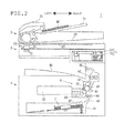
- FIG. 2 is a figure showing an internal configuration of the image forming apparatus related to the first embodiment in the present disclosure.
- Image forming apparatus 1 of the first embodiment is, for example, a printer, an MFP, or the like.
- Image forming apparatus 1 includes manuscript reading part 2, manuscript feeding part 3, body part 4, and operation part 5.
- Manuscript reading part 2 is allocated in an upper part of body part 4.
- Manuscript feeding part 3 is allocated in an upper part of manuscript reading part 2.
- Such the image forming apparatus 1 before primary feeding, makes information about a warm-up for print engine, which is need for printing that a user has a printing request (henceforth "warm-up information.") Also, image forming apparatus 1 sets up print engine based on this warm-up information. Accordingly, image forming apparatus 1 performs a first copy.
- Warm-up information here is feeding paper source information, discharging destination information, blank information, color information, or the like.
- the feeding paper source information is information for a source of feeding paper, paper size, a paper type, or the like.
- the source feeding paper is a sheet paper cassette, a paper feed tray, an intermediate tray for double-side printings, or the like.
- the discharging destination information is information for a discharging destination.
- the discharging destination is a discharging tray, a mail box, an intermediate tray for double-side printings, or the like.
- the blank information is information for being blank paper printing.
- the color information is information for which toner color is used.
- Operation part 5 which is for setting up of image forming apparatus 1 and instructing operation, is allocated in a front side of image forming apparatus 1.
- Operation part 5 includes liquid crystal display part 51 and manual operation button 52. If a user operates operation part 5, instructions are input. Accordingly, a user sets up various kinds of setting in image forming apparatus 1. Also, the user makes perform various functions, such as image formation of image forming apparatus 1.
- Liquid crystal display part 51 shows a state of image forming apparatus 1, an image formation situation and number of prints, or performs various setup.
- Liquid crystal display part 51 is, as a touch panel, various setup of function, such as double-side printing, a tone reversal, or the like, various setup, such as a magnification setup, a concentration setup, or the like, is possible.
- manual operation button 52 a start button, a stop/clear button, a reset button, a numeric keypad, or the like, are included.
- the start button is for instructing start of image formation.
- the stop/clear button is for instructing stop of image formation, or the like.
- the reset button is used for resetting the various setup of image forming apparatus 1 into a default state.
- manuscript reading part 2 includes scanner 21, platen glass 22, and manuscript reading slit 23.
- Scanner 21 has light source 24 and light receiving part 25.
- Scanner 21 is configured movable for a transportation direction of manuscript MS (manuscript) by manuscript feeding part 3.
- Manuscript reading slit 23 is a slit formed in a direction that intersects perpendicularly with the transportation direction of manuscript MS by manuscript feeding part 3.
- Manuscript feeding part 3 includes manuscript mounting part 31, manuscript discharge part 32, and manuscript transport mechanism 33.
- Manuscript MS set to manuscript mounting part 31 feed outs one sheet at a time by manuscript transport mechanism 33.
- Manuscript MS is conveyed in a position that faces manuscript reading slit 23. After that, manuscript MS is discharged by manuscript discharge part 32.
- manuscript feeding part 3 and manuscript reading part 2 are connected by a hinge mechanism on a back side of image forming apparatus 1. Therefore, manuscript feeding part 3 operates as a platen cover that opens and closes an upper surface of platen glass 22. By opening up manuscript feeding part 3, an upper surface of platen glass 22 is opened. In this case, it will be in a state where manuscript MS can be set to platen glass 22.
- scanner 21 Operation of scanner 21 is explained in a state where manuscript MS is not set to manuscript mounting part 31, and in an opened state where manuscript feeding part 3 (platen cover) is opened.
- scanner 21 The operation of scanner 21 in the state where manuscript MS is set to manuscript mounting part 31 is explained. First, reading of manuscript MS is instructed with manual operation button 52 of operation part 5. Then, manuscript MS conveyed by manuscript feeding part 3 is read. Manuscript MS is turned up a front surface (a side that reads a manuscript image) and is set to manuscript mounting part 31. Then, manuscript MS set to manuscript mounting part 31 is conveyed by manuscript feeding part 3 from left side. In this case, the front surface of manuscript MS is led to a position that faces manuscript reading slit 23. Also, scanner 21 is moved to the position that faces manuscript reading slit 23 in cases where it reads manuscript MS conveyed by manuscript feeding part 3. Scanner 21 reads manuscript MS from manuscript reading slit 23 with synchronizing conveying action by manuscript feeding part 3 and acquires image data. Scanner 21 outputs the acquired image data to control part 7 ( FIG. 3 ) in body part 4.
- Body part 4 is provided with printing part 6, and it is provided with feeding part 41, feed roller 42, paper sheet conveying path 43, resist position roller 44, and ejection roller 45.
- the registration roller is controlled by actuators (not illustrated,) such as a driving motor.
- actuators such as a driving motor.
- the actuator is omitted, and thus it is performed the cost of image forming apparatus 1 is reduced. That is, a roller in the position of the registration roller in the present embodiment does not have resist function to specify timing for feeding. Therefore, the roller in the position of the registration roller is called resist position roller 44.
- resist position roller 44 is, for example, directly linked with actuators, such as feed roller 42, and is controlled by the actuator that drives feed roller 42, or the like.
- Feeding part 41 is a sheet paper cassette that two or more sheets of paper P are contained.
- Feed roller 42 feed outs one sheet of paper P at a time to paper sheet conveying path 43 from feeding part 41.
- Paper P fed out to paper sheet conveying path 43 with feed roller 42 is conveyed to printing part 6 by resist position roller 44.
- Resist position roller 44 conveys paper P so that head of paper P supplied from the sheet paper cassette and head of an image read in the manuscript is matched.
- paper P, which is recorded by printing part 6, is discharged to ejection space 46 by ejection roller 45.
- Ejection space 46 is formed between manuscript reading part 2 and body part 4.
- feed roller 42, resist position roller 44, and ejection roller 45 operate as a conveyance part of paper P.
- feeding part 41 shown in FIG. 2 is illustrated as installed one sheet paper cassette. However, this is an example, and, in feeding part 41, it is possible to install the sheet paper cassette having a plurality of feed stages where a paper in which paper sizes differ can be set. Also, it is also possible to have another feeding source in addition to feeding part 41. Also, it is possible to install another discharging destination in ejection space 46.
- Printing part 6 is a print engine that includes photo conductor drum 61, charging part 62, exposure part 63, image formation part 64, transfer part 65, fixing part 66, and cleaning part 67.
- Exposure part 63 is an optical unit having a laser device, a mirror, or the like. Exposure part 63 outputs and exposes laser beam based on image data to photo conductor drum 61, which is uniformly electrified by charging part 62. Accordingly, an electrostatic latent image is formed on a surface of photo conductor drum 61.
- Image formation part 64 is a development unit that develops the electrostatic latent image formed on photo conductor drum 61 by using the toner and makes the toner image based on the electrostatic latent image form on photo conductor drum 61.
- Transfer part 65 makes transfer the toner image formed on photo conductor drum 61 by image formation part 64 to paper P.
- Fixing part 66 heats paper P in which the toner image is transferred by transfer part 65 and makes fix the toner image to paper P. Then, toner that remains on photo conductor drum 61 is removed by cleaning part 67.
- FIG. 3 is a figure illustrating a functional block configuration of the image forming apparatus related to the first embodiment in the present disclosure.
- manuscript reading part 2 manuscript feeding part 3
- conveyance part (feed roller 42, resist position roller 44, ejection roller 45), operation part 5, printing part 6, memory part 8, and communication part 9 are connected to control part 7.
- control part 7 Each part is operation-controlled by control part 7.
- Control part 7 has print engine control processing part 71 and printing executive operation part 72.
- Control parts 7 is an information processing part, such as a microcomputer having ROM (Read Only Memory), RAM (Random Access Memory), or the like.
- the control program for controlling operation of image forming apparatus 1 is memorized in ROM.
- Control part 7 reads the control program memorized in ROM and makes expand the control program to RAM. Accordingly, control part 7 controls a whole device according to specified instructions information inputted from operation part 5.
- Print engine control processing part 71 operation-controls a print engine having in image forming apparatus 1 by instructions from control part 7.
- Printing executive operation part 72 performs print operation by instructions from control part 7.
- Memory parts 8 is a memory part, such as semiconductor memory or HDD (Hard Disk Drive), the image data of manuscript MS read by scanner 21 is memorized, and various kinds of management information and setup information are memorized.
- HDD Hard Disk Drive
- Communication part 9 has a function that transmits and receives various data between peripheral equipment 11, such as PC (personal computer), and other image forming apparatuses 1a via networks 10, such as LAN. Also, it is configured that communication part 9 is connectable with Internet 13 via network 10 and router 12. Then, communication part 9 has a function that transmits and receives various data among the various communication equipment connected to Internet 13.
- image forming apparatus 1 cannot stop paper P in the position of resist position roller 44 of primary feeding (feeding from the sheet paper cassette to resist position roller 44) and secondary feeding (feeding from resist position roller 44.) That is, in image forming apparatus 1, primary feeding and secondary feeding are carried out continuously.
- a user sets manuscript MS to manuscript mounting part 31 of manuscript feeding part 3.
- the user inputs setup information (henceforth "print setting information") and makes a printing request.
- Print setting information has the manuscript size of manuscript MS to read, the paper size of paper P to print, the color mode of a monochrome printing or color printing, or the like.
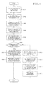
- FIG. 4 is a flow chart that shows the printing procedure in the first copy related to the first embodiment.
- control part 7 inputs the print setting information that the user set up from operation part 5.
- control part 7 extracts the image data of manuscript MS that scanner 21 read from memory part 8.
- control part 7 makes the warm-up information for the print engine.
- Control part 7 makes this warm-up information based on print setting information inputted at Step S101, manuscript size read by manuscript reading part 2, the image data inputted in Step S102, or various kinds of management information and setup information memorized in memory part 8.
- the feeding paper source information that is warm-up information is made by using information of the print setting information, feed size that the management information kept in memory part 8, or read manuscript size, or paper size based on the sheet paper cassette automatically selected based on the manuscript size, a paper type, or the like.
- the discharging destination information that is warm-up information is made by using information of the discharging destination, or the like, kept in the print setting information or the management information of memory part 8. Also, the blank information and color information that are warm-up information are made by using the color mode of print setting information and the image data.
- post conditioning information is information including existence of post conditioning, a type of post conditioning, whether bundle discharge of the paper is performed or not, or the like.
- Count-up information is information on whether it counts up or not.
- Charging information is information including unit price information according to paper, or the like.
- the above-mentioned information without regards to the drive of printing part 6 or various rollers directly may be notified after the notice of warm-up information. Accordingly, the notice time of warm-up information is shortened. As a result, the engine setup is completed quickly. Further, first copying time can be shortened.
- control part 7 starts print engine control processing part 71.
- print engine control processing part 71 starts the setup of print engine based on the warm-up information.
- it performs operation-controlling that drives the engine of feeding part 41 and feed roller 42 corresponded to the feeding paper source information of the warm-up information. Also, it performs operation-controlling that drives the engine of ejection roller 45 corresponded to the discharging destination information of the warm-up information. Also, it performs operation-controlling that sets up temperature of fixing part 66 by the paper size of paper P set to feeding part 41. Also, it performs control that sets up a developing bias of image formation part 64, or the like, by the blank information and color information of the warm-up information.
- control part 7 detects completion of the setup of print engine from print engine control processing part 71.
- control part 7 starts printing executive operation part 72.
- printing executive operation part 72 takes out paper P from feeding part 41 based on the print setting information inputted in Step S101. Also, printing executive operation part 72 makes perform the print operation. This print operation is that transfer part 65 makes transfer a toner image to paper P, and fixing part 66 heats paper P and fixes a toner image to paper P.
- control part 7 discharges paper P, which the toner is fixed, to ejection space 46 by ejection roller 45.
- the motor for registration rollers is omitted for the purpose of the cost reduction. That is, in the image forming apparatus, even if the roller exists in a registration roller position, the paper does not stop in the registration roller position. In such the image forming apparatus, the primary feeding and the secondary feeding is operated, continuously. Therefore, the setup of the print engine cannot be performed between the primary feeding and the secondary feeding. Therefore, in the image forming apparatus that a paper does not stop in the registration roller position, time of the first copy cannot be shortened.
- the print engine is set up based on warm-up information, and the paper will be fed when the setup of the print engine is completed.
- the setup of the print engine that performs operation required for printing is completed before feeding, even in cases where the paper does not stop in the registration roller position, the time of the first copy can be shortened.
- the external configuration ( FIG. 1 ), the internal configuration ( FIG. 2 ), and the functional block configuration ( FIG. 3 ) in the image forming apparatus in the second embodiment are similar to those in the first embodiment.
- the image forming apparatus of the first embodiment that the paper does not stop in the registration roller position makes the information (warm-up information) for performing the required warm-up to print engine before feeding.
- the image forming apparatus sets up the print engine required for printing based on the warm-up information, paper is fed when the setup of print engine is completed, and thus printing speed is increased.
- print engine keeps the setup state until the next printing request is received, and thus, for example, it continues consuming electric power.
- a setup state can be canceled by a timer.
- sufficient timer time is needed to have. Therefore, when the printing request is canceled in the setup state, it consumes electric power uselessly.
- image forming apparatus 1 in the second embodiment makes the warm-up information for print engine required for printing in which the user has the printing request before primary feeding. Then, print engine is set up based on this warm-up information. In addition, it has a cancel input part that inputs cancel to the printing request. Also, it has a cancel input determining part that determines whether the cancel is input or not.
- FIG. 5 is a flow chart that shows the printing request cancel procedure in the first copy related to the second embodiment.
- a user sets manuscript MS to manuscript mounting part 31 of manuscript feeding part 3. After the user inputs print setting information and makes a printing request with manual operation button 52 of operation part 5, he or she sets up cancel of the printing request by using operation part 5. Operation part 5 outputs a cancel report to control part 7, when cancel of the printing request is set up. Control part 7 inputs the cancel report.
- control part 7 inputs the print setting information that the user set up by using operation part 5.
- control part 7 extracts an image data of manuscript MS, which is read by scanner 21, from memory part 8.
- control part 7 makes warm-up information of print engine based on print setting information input in Step S201, size of manuscript read by manuscript reading part 2, image data input in Step S202, or various kinds of management information and setup information memorized in memory part 8.
- the feeding paper source information that is warm-up information is made by using information, such as the print setting information, feed size that is kept in the management information in memory part 8, or read manuscript size, or paper size and a paper type based on the sheet paper cassette automatically selected based on manuscript size.
- the discharging destination information that is warm-up information is made by using information, such as the print setting information, or the discharging destination kept in the management information in memory part 8. Also, the blank information and color information of warm-up information are made by using the color mode of the print setting information and the image data.
- the post conditioning information, the count-up information, and the charging information, or the like may be notified after the notice of warm-up information.
- control part 7 starts print engine control processing part 71.
- print engine control processing part 71 starts the setup of print engine based on the warm-up information. For example, it performs operation-controlling that drives the engine of feeding part 41 and feed roller 42 corresponded to the feeding source information of the warm-up information.
- control part 7 determines whether the cancel report of the printing request is input from operation part 5. If the cancel report is inputted (Yes in Step S206), it progresses to Step S207. If the cancel report is not inputted (No in Step S206), it progresses to Step S209.
- control part 7 performs the instructions that cancels the setup state of print engine to print engine control processing part 71.
- print engine control processing part 71 cancels the setup state of the print engine, which has been the setup state.
- control part 7 detects completion of the setup of print engine from print engine control processing part 71.
- control part 7 starts printing executive operation part 72.
- printing executive operation part 72 picked out paper P from feeding part 41 based on the print setting information inputted at Step S201, and it performs a print operation, which transfer part 65 makes transfer a toner image to paper P, fixing part 66 heats paper P, and the toner image is fixed to paper P.
- control part 7 discharges paper P, which the toner is fixed, to ejection space 46 by ejection roller 45.
- the setup state of print engine is canceled.
- power consumption can be suppressed.
- a lifetime can be prolonged by preventing wear of print engine.
Landscapes
- Physics & Mathematics (AREA)
- General Physics & Mathematics (AREA)
- Engineering & Computer Science (AREA)
- Microelectronics & Electronic Packaging (AREA)
- Control Or Security For Electrophotography (AREA)
Abstract
Description
- The present disclosure is related to an image forming apparatus and an image formation method that control an engine that prints an image of a manuscript on a paper (henceforth "print engine.")
- Typical image forming apparatuses, such as a printer or an MFP (Multifunctional Peripheral), pick out a paper from a sheet paper cassette and stop a paper with registration rollers. Accordingly, feeding operation is performed from a sheet paper cassette to a registration roller position (henceforth "primary feeding.") Also, the image forming apparatus performs another feeding operation for printing an image from a registration roller position (henceforth "secondary feeding").
- In short, feeding operation is separated into two operations. In this way, by stopping the paper with the registration rollers, a setup of the print engine that prints an image on the paper after primary feeding can be performed. Also, secondary feeding can be performed after the setup of print engine is completed. Also, the image forming apparatus that stops a paper in such a registration roller position makes setup information for performing the required setup to print engine after primary feeding. In this case, the image forming apparatus performs the setup of print engine based on this setup information.
- When the setup of print engine is completed, the image forming apparatus performs the secondary feeding and prints the image of a manuscript on the paper. In this case, the setup to print engine required after primary feeding is performed. Accordingly, when printing the manuscript on condition determined previously, time of copying a first page of the manuscript (henceforth a "first copy") can be shortened.
- An image forming apparatus of the present disclosure is an image forming apparatus that a paper does not stop in a registration roller position.
- The image forming apparatus includes a print engine control part and a warm-up information preparing part.
- The print engine control part controls operation of print engine. The warm-up information preparing part makes warm-up information. The print engine control part sets up the print engine based on the warm-up information made by the warm-up information preparing part before feeding.
- Also, an image forming apparatus includes a print engine control part, a warm-up information preparing part, a cancel input part, and a cancel input determining part. The print engine control part controls operation of print engine. The warm-up information preparing part makes warm-up information.
- The cancel input part inputs cancel for the printing request.
- The cancel input determining part determines whether or not the cancel is inputted. When it determines with the cancel being inputted by the cancel input determining part, the print engine control part cancels a setup state of the print engine set up based on the warm-up information made by the warm-up information preparing part before feeding.
- Also, an image formation method of the present disclosure is an image formation method performed by an image forming apparatus that a paper does not stop in a registration roller position. In this image formation method, operation of print engine is controlled, warm-up information is made, and the print engine is set up based on the made warm-up information before feeding.
-
FIG. 1 is a perspective view illustrating an external configuration of an image forming apparatus related to a first embodiment or a second embodiment of the present disclosure; -
FIG. 2 is a sectional view illustrating an internal configuration of the image forming apparatus related to the first embodiment or the second embodiment; -
FIG. 3 is a block diagram illustrating a functional block configuration of the image forming apparatus related to the first embodiment or the second embodiment; -
FIG. 4 is a flow chart that illustrates the printing procedure in a first copy related to the first embodiment; and -
FIG. 5 is a flow chart that illustrates the printing request cancel process in the first copy related to the second embodiment. -
FIG. 1 is a figure showing an external configuration of the image forming apparatus related to the first embodiment in the present disclosure.FIG. 2 is a figure showing an internal configuration of the image forming apparatus related to the first embodiment in the present disclosure.Image forming apparatus 1 of the first embodiment is, for example, a printer, an MFP, or the like.Image forming apparatus 1 includesmanuscript reading part 2,manuscript feeding part 3,body part 4, andoperation part 5.Manuscript reading part 2 is allocated in an upper part ofbody part 4.Manuscript feeding part 3 is allocated in an upper part ofmanuscript reading part 2. - Such the
image forming apparatus 1, before primary feeding, makes information about a warm-up for print engine, which is need for printing that a user has a printing request (henceforth "warm-up information.") Also,image forming apparatus 1 sets up print engine based on this warm-up information. Accordingly,image forming apparatus 1 performs a first copy. - Warm-up information here is feeding paper source information, discharging destination information, blank information, color information, or the like. The feeding paper source information is information for a source of feeding paper, paper size, a paper type, or the like. The source feeding paper is a sheet paper cassette, a paper feed tray, an intermediate tray for double-side printings, or the like. The discharging destination information is information for a discharging destination. The discharging destination is a discharging tray, a mail box, an intermediate tray for double-side printings, or the like. The blank information is information for being blank paper printing. The color information is information for which toner color is used.
-
Operation part 5, which is for setting up ofimage forming apparatus 1 and instructing operation, is allocated in a front side ofimage forming apparatus 1.Operation part 5 includes liquidcrystal display part 51 andmanual operation button 52. If a user operatesoperation part 5, instructions are input. Accordingly, a user sets up various kinds of setting inimage forming apparatus 1. Also, the user makes perform various functions, such as image formation ofimage forming apparatus 1. Liquidcrystal display part 51 shows a state ofimage forming apparatus 1, an image formation situation and number of prints, or performs various setup. Liquidcrystal display part 51 is, as a touch panel, various setup of function, such as double-side printing, a tone reversal, or the like, various setup, such as a magnification setup, a concentration setup, or the like, is possible. Asmanual operation button 52, a start button, a stop/clear button, a reset button, a numeric keypad, or the like, are included. The start button is for instructing start of image formation. The stop/clear button is for instructing stop of image formation, or the like. The reset button is used for resetting the various setup ofimage forming apparatus 1 into a default state. - As refer to
FIG. 2 ,manuscript reading part 2 includesscanner 21,platen glass 22, andmanuscript reading slit 23.Scanner 21 haslight source 24 andlight receiving part 25.Scanner 21 is configured movable for a transportation direction of manuscript MS (manuscript) bymanuscript feeding part 3.Manuscript reading slit 23 is a slit formed in a direction that intersects perpendicularly with the transportation direction of manuscript MS bymanuscript feeding part 3. -
Manuscript feeding part 3 includesmanuscript mounting part 31,manuscript discharge part 32, andmanuscript transport mechanism 33. Manuscript MS set tomanuscript mounting part 31 feed outs one sheet at a time bymanuscript transport mechanism 33. Manuscript MS is conveyed in a position that facesmanuscript reading slit 23. After that, manuscript MS is discharged bymanuscript discharge part 32. Also,manuscript feeding part 3 andmanuscript reading part 2 are connected by a hinge mechanism on a back side ofimage forming apparatus 1. Therefore,manuscript feeding part 3 operates as a platen cover that opens and closes an upper surface ofplaten glass 22. By opening upmanuscript feeding part 3, an upper surface ofplaten glass 22 is opened. In this case, it will be in a state where manuscript MS can be set toplaten glass 22. - Operation of
scanner 21 is explained in a state where manuscript MS is not set tomanuscript mounting part 31, and in an opened state where manuscript feeding part 3 (platen cover) is opened. - First, reading of manuscript MS is instructed with
manual operation button 52 ofoperation part 5. Then, manuscript MS set to platenglass 22 is read. In cases where it reads manuscript MS placed inplaten glass 22,scanner 21 is moved to the position that facesplaten glass 22.Scanner 21 reads manuscript MS set to platenglass 22 with scanning from vertical scanning direction datum line B to the vertical scanning direction that intersects perpendicularly with a scanning direction and acquires image data.Scanner 21 outputs the acquired image data to control part 7 (FIG. 3 ) inbody part 4. - The operation of
scanner 21 in the state where manuscript MS is set tomanuscript mounting part 31 is explained. First, reading of manuscript MS is instructed withmanual operation button 52 ofoperation part 5. Then, manuscript MS conveyed bymanuscript feeding part 3 is read. Manuscript MS is turned up a front surface (a side that reads a manuscript image) and is set tomanuscript mounting part 31. Then, manuscript MS set tomanuscript mounting part 31 is conveyed bymanuscript feeding part 3 from left side. In this case, the front surface of manuscript MS is led to a position that faces manuscript reading slit 23. Also,scanner 21 is moved to the position that faces manuscript reading slit 23 in cases where it reads manuscript MS conveyed bymanuscript feeding part 3.Scanner 21 reads manuscript MS from manuscript reading slit 23 with synchronizing conveying action bymanuscript feeding part 3 and acquires image data.Scanner 21 outputs the acquired image data to control part 7 (FIG. 3 ) inbody part 4. -
Body part 4 is provided withprinting part 6, and it is provided with feedingpart 41,feed roller 42, papersheet conveying path 43, resist position roller 44, andejection roller 45. - Typically, the registration roller is controlled by actuators (not illustrated,) such as a driving motor. On the other hand, in the present embodiment, the actuator is omitted, and thus it is performed the cost of
image forming apparatus 1 is reduced. That is, a roller in the position of the registration roller in the present embodiment does not have resist function to specify timing for feeding. Therefore, the roller in the position of the registration roller is called resist position roller 44. In addition, resist position roller 44 is, for example, directly linked with actuators, such asfeed roller 42, and is controlled by the actuator that drivesfeed roller 42, or the like. - Feeding
part 41 is a sheet paper cassette that two or more sheets of paper P are contained.Feed roller 42 feed outs one sheet of paper P at a time to papersheet conveying path 43 from feedingpart 41. Paper P fed out to papersheet conveying path 43 withfeed roller 42 is conveyed to printingpart 6 by resist position roller 44. Resist position roller 44 conveys paper P so that head of paper P supplied from the sheet paper cassette and head of an image read in the manuscript is matched. Then, paper P, which is recorded by printingpart 6, is discharged toejection space 46 byejection roller 45.Ejection space 46 is formed betweenmanuscript reading part 2 andbody part 4. Thus, feedroller 42, resist position roller 44, andejection roller 45 operate as a conveyance part of paper P. In addition, feedingpart 41 shown inFIG. 2 is illustrated as installed one sheet paper cassette. However, this is an example, and, in feedingpart 41, it is possible to install the sheet paper cassette having a plurality of feed stages where a paper in which paper sizes differ can be set. Also, it is also possible to have another feeding source in addition to feedingpart 41. Also, it is possible to install another discharging destination inejection space 46. - Printing
part 6 is a print engine that includesphoto conductor drum 61, chargingpart 62,exposure part 63,image formation part 64,transfer part 65, fixingpart 66, and cleaningpart 67.Exposure part 63 is an optical unit having a laser device, a mirror, or the like.Exposure part 63 outputs and exposes laser beam based on image data tophoto conductor drum 61, which is uniformly electrified by chargingpart 62. Accordingly, an electrostatic latent image is formed on a surface ofphoto conductor drum 61.Image formation part 64 is a development unit that develops the electrostatic latent image formed onphoto conductor drum 61 by using the toner and makes the toner image based on the electrostatic latent image form onphoto conductor drum 61.Transfer part 65 makes transfer the toner image formed onphoto conductor drum 61 byimage formation part 64 to paperP. Fixing part 66 heats paper P in which the toner image is transferred bytransfer part 65 and makes fix the toner image to paper P. Then, toner that remains onphoto conductor drum 61 is removed by cleaningpart 67. -
FIG. 3 is a figure illustrating a functional block configuration of the image forming apparatus related to the first embodiment in the present disclosure. Above-mentionedmanuscript reading part 2,manuscript feeding part 3, conveyance part (feedroller 42, resist position roller 44, ejection roller 45),operation part 5, printingpart 6,memory part 8, andcommunication part 9 are connected to controlpart 7. Each part is operation-controlled bycontrol part 7. -
Control part 7 has print enginecontrol processing part 71 and printingexecutive operation part 72. -
Control parts 7 is an information processing part, such as a microcomputer having ROM (Read Only Memory), RAM (Random Access Memory), or the like. The control program for controlling operation ofimage forming apparatus 1 is memorized in ROM.Control part 7 reads the control program memorized in ROM and makes expand the control program to RAM. Accordingly, controlpart 7 controls a whole device according to specified instructions information inputted fromoperation part 5. Print enginecontrol processing part 71 operation-controls a print engine having inimage forming apparatus 1 by instructions fromcontrol part 7. Printingexecutive operation part 72 performs print operation by instructions fromcontrol part 7. -
Memory parts 8 is a memory part, such as semiconductor memory or HDD (Hard Disk Drive), the image data of manuscript MS read byscanner 21 is memorized, and various kinds of management information and setup information are memorized. -
Communication part 9 has a function that transmits and receives various data betweenperipheral equipment 11, such as PC (personal computer), and otherimage forming apparatuses 1a vianetworks 10, such as LAN. Also, it is configured thatcommunication part 9 is connectable withInternet 13 vianetwork 10 androuter 12. Then,communication part 9 has a function that transmits and receives various data among the various communication equipment connected toInternet 13. - Then, a printing procedure in the first copy in
image forming apparatus 1 is explained by using a flow chart shown inFIG. 4 . - Here,
image forming apparatus 1 cannot stop paper P in the position of resist position roller 44 of primary feeding (feeding from the sheet paper cassette to resist position roller 44) and secondary feeding (feeding from resist position roller 44.) That is, inimage forming apparatus 1, primary feeding and secondary feeding are carried out continuously. - A user sets manuscript MS to
manuscript mounting part 31 ofmanuscript feeding part 3. By usingmanual operation button 52 ofoperation part 5, the user inputs setup information (henceforth "print setting information") and makes a printing request. Print setting information has the manuscript size of manuscript MS to read, the paper size of paper P to print, the color mode of a monochrome printing or color printing, or the like. -
FIG. 4 is a flow chart that shows the printing procedure in the first copy related to the first embodiment. - First, control
part 7 inputs the print setting information that the user set up fromoperation part 5. - Next, control
part 7 extracts the image data of manuscript MS thatscanner 21 read frommemory part 8. - Next, control
part 7 makes the warm-up information for the print engine.Control part 7 makes this warm-up information based on print setting information inputted at Step S101, manuscript size read bymanuscript reading part 2, the image data inputted in Step S102, or various kinds of management information and setup information memorized inmemory part 8. - For example, the feeding paper source information that is warm-up information is made by using information of the print setting information, feed size that the management information kept in
memory part 8, or read manuscript size, or paper size based on the sheet paper cassette automatically selected based on the manuscript size, a paper type, or the like. - Also, the discharging destination information that is warm-up information is made by using information of the discharging destination, or the like, kept in the print setting information or the management information of
memory part 8. Also, the blank information and color information that are warm-up information are made by using the color mode of print setting information and the image data. - In a typical image forming apparatus that a paper stops in the registration roller position, after primary feeding, with the warm-up information for print engine, for example, post conditioning information, count-up information, charging information, or the like, are notified to print engine. Post conditioning information is information including existence of post conditioning, a type of post conditioning, whether bundle discharge of the paper is performed or not, or the like. Count-up information is information on whether it counts up or not. Charging information is information including unit price information according to paper, or the like.
- As compared with this, in the image forming apparatus that the paper does not stop in the registration roller position in the present embodiment, the above-mentioned information without regards to the drive of printing
part 6 or various rollers directly may be notified after the notice of warm-up information. Accordingly, the notice time of warm-up information is shortened. As a result, the engine setup is completed quickly. Further, first copying time can be shortened. - Next, control
part 7 starts print enginecontrol processing part 71. - Next, print engine
control processing part 71 starts the setup of print engine based on the warm-up information. - For example, it performs operation-controlling that drives the engine of feeding
part 41 andfeed roller 42 corresponded to the feeding paper source information of the warm-up information. Also, it performs operation-controlling that drives the engine ofejection roller 45 corresponded to the discharging destination information of the warm-up information. Also, it performs operation-controlling that sets up temperature of fixingpart 66 by the paper size of paper P set to feedingpart 41. Also, it performs control that sets up a developing bias ofimage formation part 64, or the like, by the blank information and color information of the warm-up information. - Next, control
part 7 detects completion of the setup of print engine from print enginecontrol processing part 71. - Next, control
part 7 starts printingexecutive operation part 72. - Next, printing
executive operation part 72 takes out paper P from feedingpart 41 based on the print setting information inputted in Step S101. Also, printingexecutive operation part 72 makes perform the print operation. This print operation is thattransfer part 65 makes transfer a toner image to paper P, and fixingpart 66 heats paper P and fixes a toner image to paper P. - Next, control
part 7 discharges paper P, which the toner is fixed, toejection space 46 byejection roller 45. - As mentioned above, in the image forming apparatus of a first embodiment, the motor for registration rollers is omitted for the purpose of the cost reduction. That is, in the image forming apparatus, even if the roller exists in a registration roller position, the paper does not stop in the registration roller position. In such the image forming apparatus, the primary feeding and the secondary feeding is operated, continuously. Therefore, the setup of the print engine cannot be performed between the primary feeding and the secondary feeding. Therefore, in the image forming apparatus that a paper does not stop in the registration roller position, time of the first copy cannot be shortened.
- Accordingly, in the image forming apparatus of the first embodiment, the print engine is set up based on warm-up information, and the paper will be fed when the setup of the print engine is completed. Thus, since the setup of the print engine that performs operation required for printing is completed before feeding, even in cases where the paper does not stop in the registration roller position, the time of the first copy can be shortened.
- In the external configuration (
FIG. 1 ), the internal configuration (FIG. 2 ), and the functional block configuration (FIG. 3 ) in the image forming apparatus in the second embodiment are similar to those in the first embodiment. - The image forming apparatus of the first embodiment that the paper does not stop in the registration roller position makes the information (warm-up information) for performing the required warm-up to print engine before feeding. The image forming apparatus sets up the print engine required for printing based on the warm-up information, paper is fed when the setup of print engine is completed, and thus printing speed is increased.
- However, in the state during the setup of print engine or being completed the setup (henceforth a "setup state"), when paper is not fed and the printing request is canceled by the user, print engine keeps the setup state until the next printing request is received, and thus, for example, it continues consuming electric power.
- This is because, in the control of print engine, although the notice of cancel is performed to the print engine in cases where a paper is conveying, the notice of cancel is not performed to the print engine in cases where a paper is not conveying.
- In addition, in a typical image forming apparatus that the paper stops in the registration roller position, after primary feeding, the setup of the print engine is completed based on warm-up information. Accordingly, primary feeding is completed even if the printing request is canceled in the state of the setup (a paper is conveying). Therefore, the notice of cancel is performed to the print engine, and the setup state based on warm-up information is canceled.
- For example, in the image forming apparatus of the first embodiment that the paper does not stop in the registration roller position, a setup state can be canceled by a timer. However, since there is no telling when the next printing request comes, sufficient timer time is needed to have. Therefore, when the printing request is canceled in the setup state, it consumes electric power uselessly.
- Consequently,
image forming apparatus 1 in the second embodiment makes the warm-up information for print engine required for printing in which the user has the printing request before primary feeding. Then, print engine is set up based on this warm-up information. In addition, it has a cancel input part that inputs cancel to the printing request. Also, it has a cancel input determining part that determines whether the cancel is input or not. -
FIG. 5 is a flow chart that shows the printing request cancel procedure in the first copy related to the second embodiment. - On the conditions of the first copy, a user sets manuscript MS to
manuscript mounting part 31 ofmanuscript feeding part 3. After the user inputs print setting information and makes a printing request withmanual operation button 52 ofoperation part 5, he or she sets up cancel of the printing request by usingoperation part 5.Operation part 5 outputs a cancel report to controlpart 7, when cancel of the printing request is set up.Control part 7 inputs the cancel report. - First, control
part 7 inputs the print setting information that the user set up by usingoperation part 5. - Next, control
part 7 extracts an image data of manuscript MS, which is read byscanner 21, frommemory part 8. - Next, control
part 7 makes warm-up information of print engine based on print setting information input in Step S201, size of manuscript read bymanuscript reading part 2, image data input in Step S202, or various kinds of management information and setup information memorized inmemory part 8. - For example, the feeding paper source information that is warm-up information is made by using information, such as the print setting information, feed size that is kept in the management information in
memory part 8, or read manuscript size, or paper size and a paper type based on the sheet paper cassette automatically selected based on manuscript size. - Also, the discharging destination information that is warm-up information is made by using information, such as the print setting information, or the discharging destination kept in the management information in
memory part 8. Also, the blank information and color information of warm-up information are made by using the color mode of the print setting information and the image data. - In the image forming apparatus which a paper does not stop in the registration roller position of the present embodiment, about the post conditioning information, the count-up information, and the charging information, or the like, these may be notified after the notice of warm-up information.
- These are not concerned driving
printing part 6 or various rollers, directly. This is the same as that of the above-mentioned first embodiment. Thereby, the notice time of the warm-up information is shortened, the engine setup is completed quickly, and further first copying time can be shortened. - Next, control
part 7 starts print enginecontrol processing part 71. - Next, print engine
control processing part 71 starts the setup of print engine based on the warm-up information. For example, it performs operation-controlling that drives the engine of feedingpart 41 andfeed roller 42 corresponded to the feeding source information of the warm-up information. - Also, it performs operation-controlling that drives the engine of
ejection roller 45 corresponded to the discharging destination information of the warm-up information. Also, it performs operation-controlling that sets up the temperature of fixingpart 66 by the paper size of paper P set to feedingpart 41. Also, it performs control that set up the developing bias ofimage formation part 64, or the like, by the blank information and color information of the warm-up information. - Next, control
part 7 determines whether the cancel report of the printing request is input fromoperation part 5. If the cancel report is inputted (Yes in Step S206), it progresses to Step S207. If the cancel report is not inputted (No in Step S206), it progresses to Step S209. - Next, control
part 7 performs the instructions that cancels the setup state of print engine to print enginecontrol processing part 71. - Next, print engine
control processing part 71 cancels the setup state of the print engine, which has been the setup state. - Next, control
part 7 detects completion of the setup of print engine from print enginecontrol processing part 71. - Next, control
part 7 starts printingexecutive operation part 72. - Next, printing
executive operation part 72 picked out paper P from feedingpart 41 based on the print setting information inputted at Step S201, and it performs a print operation, which transferpart 65 makes transfer a toner image to paper P, fixingpart 66 heats paper P, and the toner image is fixed to paper P. - Next, control
part 7 discharges paper P, which the toner is fixed, toejection space 46 byejection roller 45. - As mentioned above, in the second embodiment, for the image forming apparatus of low cost that a paper does not stop in the registration roller position, when a printing request is canceled, the setup state of print engine is canceled. Thereby, power consumption can be suppressed. Also, a lifetime can be prolonged by preventing wear of print engine.
Claims (10)
- An image forming apparatus that a paper does not stop in a registration roller position, characterized in that comprising:a print engine control part that controls operation of a print engine;a warm-up information preparing part that makes warm-up information,wherein the print engine control part set up, before feeding, the print engine based on the warm-up information made by the warm-up information preparing part.
- The image forming apparatus according to claim 1, characterized in that
the warm-up information is at least one of feeding paper source information, discharging destination information, blank information, and color information. - The image forming apparatus according to claim 1 or 2, characterized in that
the warm-up information is information for performing a setup at least one of a photo conductor drum, a charging part, an exposure part, an image formation part, a transfer part, a fixing part, a cleaning part, and an actuator of a roller. - The image forming apparatus according to any one of claims 1 to 3, further comprising a printing executive operation part that performs print operation, wherein when completion of the warm-up of the print engine control part is detected, the printing executive operation part performs print operation.
- The image forming apparatus according to any one of claims 1 to 4, further comprising:a cancel input part that inputs cancel for a printing request;a cancel input determining part that determines the cancel is input,wherein when determining input the cancel by the cancel input determining part, the print engine control part cancels a setup state of the print engine, which is set up based on the warm-up information made by the warm-up information preparing part before feeding.
- An image forming apparatus that a paper does not stop in a registration roller position, characterized in that comprising:a print engine control part that controls operation of print engine;a warm-up information preparing part that makes warm-up information;a cancel input part that inputs cancel for a printing request;a cancel input determining part that determines the cancel is input,wherein when determining input the cancel by the cancel input determining part, the print engine control part cancels a setup state of the print engine set up based on the warm-up information made by the warm-up information preparing part before feeding.
- The image forming apparatus according to claim 6, characterized in that
the warm-up information is at least one of feeding paper source information, discharging destination information, blank information, and color information. - The image forming apparatus according to claim 6 or 7, characterized in that
the warm-up information is information for performing a setup at least one of a photo conductor drum, a charging part, an exposure part, an image formation part, a transfer part, a fixing part, a cleaning part, and an actuator of a roller. - The image forming apparatus according to any one of claims 6 to 8, further comprising a printing executive operation part that performs print operation,
wherein when determining not input cancel by the cancel input determining part, the print operation is performed by the printing executive operation part. - An image formation method performed by the image forming apparatus that a paper does not stop in a registration roller position, characterized in that comprising the steps of:controlling operation of print engine;making warm-up information; andsetting up the print engine before feeding based on the warm-up information.
Applications Claiming Priority (2)
| Application Number | Priority Date | Filing Date | Title |
|---|---|---|---|
| JP2014036236A JP6084939B2 (en) | 2014-02-27 | 2014-02-27 | Image forming apparatus |
| JP2014036235A JP6084938B2 (en) | 2014-02-27 | 2014-02-27 | Image forming apparatus |
Publications (1)
| Publication Number | Publication Date |
|---|---|
| EP2913718A1 true EP2913718A1 (en) | 2015-09-02 |
Family
ID=52726926
Family Applications (1)
| Application Number | Title | Priority Date | Filing Date |
|---|---|---|---|
| EP15156677.5A Withdrawn EP2913718A1 (en) | 2014-02-27 | 2015-02-26 | Image forming apparatus and image formation method that paper does not stop in registration roller position |
Country Status (3)
| Country | Link |
|---|---|
| US (1) | US9316980B2 (en) |
| EP (1) | EP2913718A1 (en) |
| CN (1) | CN104880920B (en) |
Families Citing this family (1)
| Publication number | Priority date | Publication date | Assignee | Title |
|---|---|---|---|---|
| JP6544088B2 (en) * | 2015-07-06 | 2019-07-17 | 富士通株式会社 | Terminal, information leak prevention method and information leak prevention program |
Citations (7)
| Publication number | Priority date | Publication date | Assignee | Title |
|---|---|---|---|---|
| JPS56137365A (en) * | 1980-03-28 | 1981-10-27 | Ricoh Co Ltd | Synchronous control system of copying machine |
| US6172762B1 (en) * | 1993-03-10 | 2001-01-09 | Minolta Co., Ltd. | Printer system with power-up controller |
| JP2004262026A (en) * | 2003-02-28 | 2004-09-24 | Kyocera Mita Corp | Image forming apparatus |
| US20070047993A1 (en) * | 2005-08-30 | 2007-03-01 | Xerox Corporation | System for managing a digital printer having active and inactive operational modes |
| JP2012123268A (en) * | 2010-12-09 | 2012-06-28 | Canon Inc | Image forming apparatus |
| US20120224224A1 (en) * | 2011-03-02 | 2012-09-06 | Seiko Epson Corporation | Printing apparatus and printing method |
| EP2667256A2 (en) * | 2012-05-21 | 2013-11-27 | Canon Kabushiki Kaisha | Image forming apparatus, control method for image forming apparatus, and storage medium |
Family Cites Families (5)
| Publication number | Priority date | Publication date | Assignee | Title |
|---|---|---|---|---|
| JPH0930079A (en) * | 1995-07-13 | 1997-02-04 | Fuji Xerox Co Ltd | Printing device |
| JP2008009216A (en) | 2006-06-30 | 2008-01-17 | Kyocera Mita Corp | Image forming apparatus and image forming program |
| JP2011118211A (en) * | 2009-12-04 | 2011-06-16 | Canon Inc | Image forming apparatus, method and program of controlling the image forming apparatus |
| JP6028553B2 (en) * | 2011-12-21 | 2016-11-16 | 株式会社リコー | Recording medium conveying apparatus, image forming apparatus, recording medium conveying method, and image forming system |
| JP6149378B2 (en) * | 2012-10-24 | 2017-06-21 | ブラザー工業株式会社 | Image forming apparatus |
-
2015
- 2015-02-26 EP EP15156677.5A patent/EP2913718A1/en not_active Withdrawn
- 2015-02-26 CN CN201510088878.XA patent/CN104880920B/en not_active Expired - Fee Related
- 2015-02-27 US US14/633,698 patent/US9316980B2/en active Active
Patent Citations (7)
| Publication number | Priority date | Publication date | Assignee | Title |
|---|---|---|---|---|
| JPS56137365A (en) * | 1980-03-28 | 1981-10-27 | Ricoh Co Ltd | Synchronous control system of copying machine |
| US6172762B1 (en) * | 1993-03-10 | 2001-01-09 | Minolta Co., Ltd. | Printer system with power-up controller |
| JP2004262026A (en) * | 2003-02-28 | 2004-09-24 | Kyocera Mita Corp | Image forming apparatus |
| US20070047993A1 (en) * | 2005-08-30 | 2007-03-01 | Xerox Corporation | System for managing a digital printer having active and inactive operational modes |
| JP2012123268A (en) * | 2010-12-09 | 2012-06-28 | Canon Inc | Image forming apparatus |
| US20120224224A1 (en) * | 2011-03-02 | 2012-09-06 | Seiko Epson Corporation | Printing apparatus and printing method |
| EP2667256A2 (en) * | 2012-05-21 | 2013-11-27 | Canon Kabushiki Kaisha | Image forming apparatus, control method for image forming apparatus, and storage medium |
Also Published As
| Publication number | Publication date |
|---|---|
| CN104880920A (en) | 2015-09-02 |
| CN104880920B (en) | 2018-08-17 |
| US9316980B2 (en) | 2016-04-19 |
| US20150241827A1 (en) | 2015-08-27 |
Similar Documents
| Publication | Publication Date | Title |
|---|---|---|
| JP6213378B2 (en) | Image forming apparatus and image forming method | |
| US9316980B2 (en) | Image forming apparatus and image formation method that paper does not stop in registration roller position | |
| JP2010008819A (en) | Printer and printing method | |
| JP4574441B2 (en) | Image forming apparatus and control method thereof | |
| JP2004226492A (en) | Image forming apparatus and copying apparatus | |
| JP6361521B2 (en) | Image forming apparatus | |
| US9682588B2 (en) | Image forming apparatus and method for processing reused sheet | |
| JP3227187B2 (en) | Image forming device | |
| JP4538270B2 (en) | Image reading apparatus and image forming apparatus | |
| JP5790111B2 (en) | Image forming apparatus, control method, and control program | |
| JP2015138249A (en) | image forming apparatus | |
| US10496000B2 (en) | Image forming apparatus, image forming method and non-transitory computer-readable recording medium encoded with image forming program | |
| JP2004155522A (en) | Image forming device | |
| JP6121318B2 (en) | Image forming apparatus | |
| JP6319131B2 (en) | Image forming apparatus | |
| JP6084939B2 (en) | Image forming apparatus | |
| JP6274123B2 (en) | Image forming apparatus | |
| JP6084938B2 (en) | Image forming apparatus | |
| US6542714B1 (en) | Image forming method and apparatus that uses an external sheet discharge tray for double-side copying | |
| JP5940031B2 (en) | Image forming apparatus | |
| JP2016142800A (en) | Image forming apparatus | |
| JP2004074475A (en) | Image output apparatus | |
| JPH08328433A (en) | Power supply for compound copier | |
| JP2006133578A (en) | Image forming apparatus, control method, and program | |
| JP2016208154A (en) | Image forming apparatus and control program |
Legal Events
| Date | Code | Title | Description |
|---|---|---|---|
| PUAI | Public reference made under article 153(3) epc to a published international application that has entered the european phase |
Free format text: ORIGINAL CODE: 0009012 |
|
| AK | Designated contracting states |
Kind code of ref document: A1 Designated state(s): AL AT BE BG CH CY CZ DE DK EE ES FI FR GB GR HR HU IE IS IT LI LT LU LV MC MK MT NL NO PL PT RO RS SE SI SK SM TR |
|
| AX | Request for extension of the european patent |
Extension state: BA ME |
|
| 17P | Request for examination filed |
Effective date: 20160301 |
|
| RBV | Designated contracting states (corrected) |
Designated state(s): AL AT BE BG CH CY CZ DE DK EE ES FI FR GB GR HR HU IE IS IT LI LT LU LV MC MK MT NL NO PL PT RO RS SE SI SK SM TR |
|
| 17Q | First examination report despatched |
Effective date: 20200818 |
|
| STAA | Information on the status of an ep patent application or granted ep patent |
Free format text: STATUS: THE APPLICATION IS DEEMED TO BE WITHDRAWN |
|
| 18D | Application deemed to be withdrawn |
Effective date: 20201124 |