EP2913698A1 - Light conducting component and field bus module - Google Patents
Light conducting component and field bus module Download PDFInfo
- Publication number
- EP2913698A1 EP2913698A1 EP15156382.2A EP15156382A EP2913698A1 EP 2913698 A1 EP2913698 A1 EP 2913698A1 EP 15156382 A EP15156382 A EP 15156382A EP 2913698 A1 EP2913698 A1 EP 2913698A1
- Authority
- EP
- European Patent Office
- Prior art keywords
- light
- conducting component
- main body
- field bus
- reflection
- Prior art date
- Legal status (The legal status is an assumption and is not a legal conclusion. Google has not performed a legal analysis and makes no representation as to the accuracy of the status listed.)
- Granted
Links
- 229920003023 plastic Polymers 0.000 claims description 5
- 150000001875 compounds Chemical class 0.000 claims description 4
- 238000004382 potting Methods 0.000 claims description 4
- 230000007704 transition Effects 0.000 claims description 4
- 229920003229 poly(methyl methacrylate) Polymers 0.000 claims description 2
- 239000004417 polycarbonate Substances 0.000 claims description 2
- 229920000515 polycarbonate Polymers 0.000 claims description 2
- 239000004926 polymethyl methacrylate Substances 0.000 claims description 2
- 239000007787 solid Substances 0.000 description 7
- 238000009826 distribution Methods 0.000 description 6
- 230000003287 optical effect Effects 0.000 description 3
- 239000003086 colorant Substances 0.000 description 2
- 230000000694 effects Effects 0.000 description 2
- 230000003628 erosive effect Effects 0.000 description 2
- 239000000945 filler Substances 0.000 description 2
- 239000000463 material Substances 0.000 description 2
- 239000000203 mixture Substances 0.000 description 2
- 230000001419 dependent effect Effects 0.000 description 1
- 239000006185 dispersion Substances 0.000 description 1
- 239000008240 homogeneous mixture Substances 0.000 description 1
- 238000005286 illumination Methods 0.000 description 1
- 238000007373 indentation Methods 0.000 description 1
- 238000001746 injection moulding Methods 0.000 description 1
- 238000009434 installation Methods 0.000 description 1
- 238000004519 manufacturing process Methods 0.000 description 1
- 238000000034 method Methods 0.000 description 1
- 238000010137 moulding (plastic) Methods 0.000 description 1
- 239000013307 optical fiber Substances 0.000 description 1
- 230000003071 parasitic effect Effects 0.000 description 1
- 239000002245 particle Substances 0.000 description 1
- 238000007788 roughening Methods 0.000 description 1
- 239000012780 transparent material Substances 0.000 description 1
Images

Classifications
-
- G—PHYSICS
- G02—OPTICS
- G02B—OPTICAL ELEMENTS, SYSTEMS OR APPARATUS
- G02B19/00—Condensers, e.g. light collectors or similar non-imaging optics
- G02B19/0033—Condensers, e.g. light collectors or similar non-imaging optics characterised by the use
- G02B19/0047—Condensers, e.g. light collectors or similar non-imaging optics characterised by the use for use with a light source
- G02B19/0061—Condensers, e.g. light collectors or similar non-imaging optics characterised by the use for use with a light source the light source comprising a LED
-
- G—PHYSICS
- G02—OPTICS
- G02B—OPTICAL ELEMENTS, SYSTEMS OR APPARATUS
- G02B6/00—Light guides; Structural details of arrangements comprising light guides and other optical elements, e.g. couplings
- G02B6/0001—Light guides; Structural details of arrangements comprising light guides and other optical elements, e.g. couplings specially adapted for lighting devices or systems
- G02B6/0005—Light guides; Structural details of arrangements comprising light guides and other optical elements, e.g. couplings specially adapted for lighting devices or systems the light guides being of the fibre type
- G02B6/0008—Light guides; Structural details of arrangements comprising light guides and other optical elements, e.g. couplings specially adapted for lighting devices or systems the light guides being of the fibre type the light being emitted at the end of the fibre
Abstract
Ein lichtleitendes Bauteil (10) zur Verwendung in einem Feldbusmodul (22) ist beschrieben, wobei das lichtleitende Bauteil (10) einen Hauptkörper (12), durch den sich Licht entlang einer definierten Lichtausbreitungsrichtung ausbreiten kann, und ein Austrittselement (14) an einem Ende (13b) des Hauptkörpers (12) hat. An dem Austrittselement (14) kann das Licht aus dem lichtleitenden Bauteil (10) auskoppeln, wobei wenigstens ein Reflexionselement (20) in Lichtausbreitungsrichtung vor dem Austrittselement (14) angeordnet ist, an dem zumindest ein Teil des Lichts reflektiert werden kann. Ferner ist ein Feldbusmodul (22) mit einem lichtleitenden Bauteil (10) beschrieben.A photoconductive member (10) for use in a fieldbus module (22) is described wherein the photoconductive member (10) has a main body (12) through which light propagates along a defined direction of light propagation and an exit member (14) at one end (13b) of the main body (12). At the exit element (14), the light can be coupled out of the light-conducting component (10), wherein at least one reflection element (20) is arranged in the light propagation direction in front of the exit element (14), on which at least part of the light can be reflected. Furthermore, a field bus module (22) with a light-conducting component (10) is described.
Description
Die Erfindung betrifft ein lichtleitendes Bauteil zur Verwendung in einem Feldbusmodul sowie ein Feldbusmodul.The invention relates to a light-conducting component for use in a field bus module and a field bus module.
Generell stellen lichtleitende Bauteile eine Unterkategorie der Lichtleiter dar und grenzen sich von Lichtwellenleitern ab, die ebenfalls eine Unterkategorie der Lichtleiter sind. Die lichtleitenden Bauteile leiten das von einer Lichtquelle ausgesandte Licht zu einem Ort, an dem das Licht der Lichtquelle gesehen werden soll. Die lichtleitenden Bauteile sind typischerweise als Vollkörper ausgebildet, durch den das Licht in einer bestimmten Lichtausbreitungsrichtung verläuft, die im Wesentlichen parallel zur Längserstreckung des lichtleitenden Bauteils ist. Üblicherweise sind die lichtleitenden Bauteile aus einem transparenten Material gebildet und übertragen das Licht nur über kurze Distanzen. Das eingekoppelte Licht koppelt nach dem Durchlaufen des lichtleitenden Bauteils am vorgesehenen Ort an einer Austrittsfläche des lichtleitenden Bauteils aus.In general, light-conducting components represent a sub-category of light guides and are distinct from optical fibers, which are also a sub-category of light guides. The light-conducting components direct the light emitted by a light source to a location where the light of the light source is to be seen. The light-conducting components are typically formed as a solid body, through which the light extends in a specific light propagation direction, which is substantially parallel to the longitudinal extent of the light-conducting component. Usually, the light-conducting components are formed of a transparent material and transmit the light only over short distances. The coupled light coupled after passing through the photoconductive member at the intended location at an exit surface of the photoconductive member.
Im Gegensatz dazu werden in Lichtwellenleiter Lichtsignale übertragen, indem das Licht unter einem bestimmten Winkel auf eine Ummantelung des Lichtwellenleiters trifft, um somit innerhalb des Lichtwellenleiters total reflektiert zu werden und möglichst verlustfrei über größere Entfernungen übertragen werden zu können.In contrast, light signals are transmitted in optical waveguides by the light strikes a sheath of the optical waveguide at a certain angle, so as to be totally reflected within the optical waveguide and loss-free over longer distances can be transmitted.
Die lichtleitenden Bauteile werden beispielsweise bei Feldbusmodulen verwendet, um die Aktivität eines Anschlusses oder einen Zustand des Feldbusmoduls oder des Anschlusses anzuzeigen. Hierzu wird das von einer innerhalb des Feldbusmoduls angeordneten Lichtquelle ausgesandte Signal vom lichtleitenden Bauteil an die Oberfläche des Feldbusmoduls übertragen, sodass dies von einem Nutzer gesehen werden kann.The photoconductive devices are used, for example, in fieldbus modules to indicate the activity of a port or a state of the fieldbus module or port. For this purpose, the signal emitted by a light source arranged within the fieldbus module is transmitted from the light-conducting component to the surface of the field bus module, so that this can be seen by a user.
Aufgrund der dezentralen Verwendung der Feldbusmodule und den damit verbundenen unterschiedlichen Einbaulagen der Feldbusmodule kann es vorkommen, dass nur eine seitliche Sicht auf das lichtleitende Bauteil möglich ist. Da sich das Licht im lichtleitenden Bauteil jedoch nur parallel zur Längserstreckung des lichtleitenden Bauteils ausbreitet, ist die seitliche Sichtbarkeit an der Austrittsfläche des lichtleitenden Bauteils gering, sodass das Licht schlecht zu sehen ist. Dieses Problem verstärkt sich bei einer hellen Umgebung. Im Stand der Technik wurde versucht das Problem dadurch zu lösen, dass die Austrittsfläche des Lichts am lichtleitenden Bauteil aufgeraut wird. Hiermit konnte das Problem der schlechten seitlichen Sichtbarkeit jedoch nicht zufriedenstellend behoben werden.Due to the decentralized use of the fieldbus modules and the associated different mounting positions of the fieldbus modules, it can occur that only a lateral view of the light-conducting component is possible. However, since the light in the photoconductive member propagates only parallel to the longitudinal extent of the photoconductive member, the lateral visibility at the exit surface of the photoconductive member is low, so that the light is difficult to see. This problem increases in a bright environment. In the prior art, an attempt was made to solve the problem by roughening the exit surface of the light at the light-conducting component. However, this did not solve the problem of poor lateral visibility satisfactorily.
Es ist daher Aufgabe der Erfindung, ein lichtleitendes Bauteil bereitzustellen, das eine gute Sichtbarkeit über einen großen Betrachtungswinkel aufweist.It is therefore an object of the invention to provide a photoconductive member having good visibility over a wide viewing angle.
Die Aufgabe der Erfindung wird durch ein lichtleitendes Bauteil zur Verwendung in einem Feldbusmodul gelöst, wobei das lichtleitende Bauteil einen Hauptkörper, durch den sich Licht entlang einer definierten Lichtausbreitungsrichtung ausbreiten kann, und ein Austrittselement an einem Ende des Hauptkörpers hat, an dem das Licht aus dem lichtleitenden Bauteil auskoppeln kann, wobei wenigstens ein Reflexionselement in Lichtausbreitungsrichtung vor dem Austrittselement angeordnet ist, an dem zumindest ein Teil des Lichts reflektiert werden kann. Der Grundgedanke der Erfindung ist es, die seitliche Sichtbarkeit des lichtleitenden Bauteils dadurch zu erhöhen, dass wenigstens ein Reflexionselement im oder am lichtleitenden Bauteil angeordnet ist, an dem das ausgesandte Licht reflektiert und gestreut wird. Durch die damit verbundene Streuung des Lichts ergibt sich eine bessere seitliche Sichtbarkeit, da die Lichtstrahlen am Austrittselement nicht nur senkrecht zur Austrittsfläche auskoppeln.The object of the invention is achieved by a light-conducting component for use in a field bus module, wherein the light-conducting component has a main body, through which light can propagate along a defined light propagation direction, and an outlet member at one end of the main body, at which the light from the can decouple light-conducting component, wherein at least one reflection element is arranged in the light propagation direction in front of the outlet element, on which at least a portion of the light can be reflected. The basic idea of the invention is to increase the lateral visibility of the light-conducting component in that at least one reflection element is arranged in or on the light-conducting component, on which the emitted light is reflected and scattered. The associated scattering of the light results in a better lateral visibility, since the light beams at the exit element not only decouple perpendicular to the exit surface.
Insbesondere reflektiert der Teil des Lichts derart, dass das Licht im Wesentlichen isotrop in einem Winkelbereich von etwa -90° bis etwa +90° zur Lichtausbreitungsrichtung am Austrittselement auskoppelt. Hierdurch ist es möglich, dass das ausgekoppelte Licht in Draufsicht sowie aus beliebigen Blinkwinkeln erkannt werden kann, insbesondere in einer Seitenansicht. Es ergibt sich also eine gute seitliche sowie frontale Sichtbarkeit. Aufgrund der isotropen Verteilung im Winkelbereich von etwa -90° bis etwa +90° zur Lichtausbreitungsrichtung koppeln die Lichtstrahlen in einer Querschnittsansicht halbkreisförmig am Austrittselement aus. Für das menschliche Auge ergibt sich aufgrund der Streuung und der Reflexion des Lichts eine im Wesentlichen isotrope Verteilung in diesem Winkelbereich, wobei Intensitätsschwankungen des Lichts von einigen Prozent auftreten können. Diese sind aber so gering, dass sie fast nicht wahrgenommen werden.In particular, the part of the light reflects such that the light decouples substantially isotropically in an angular range of about -90 ° to about + 90 ° to the light propagation direction at the exit element. This makes it possible that the decoupled light can be detected in plan view and from any flashing angles, in particular in a side view. This results in a good lateral and frontal visibility. Due to the isotropic distribution in the angular range of about -90 ° to about + 90 ° to the light propagation direction, the light beams couple in a cross-sectional view semicircular at the exit element. Due to the scattering and the reflection of the light, a substantially isotropic distribution in this angular range results for the human eye, whereby intensity fluctuations of the light of a few percent can occur. These are so small that they are almost unnoticeable.
Gemäß einem Aspekt der Erfindung ist der Hauptkörper als Lichtleitstab ausgebildet, insbesondere aus einem transparenten Kunststoff wie PMMA oder Polycarbonat. Der Hauptkörper ist als ein Vollkörper ausgebildet, der aus einem Material besteht, durch den sich das Licht ausbreiten kann. Der Hauptkörper kann zudem aufgrund des transparenten Kunststoffs kostengünstig hergestellt werden. Ferner kann der Hauptkörper ein vollständig gegossenes Bauteil sein.According to one aspect of the invention, the main body is designed as a light-conducting rod, in particular made of a transparent plastic such as PMMA or polycarbonate. The main body is formed as a solid body made of a material through which the light can propagate. The main body can also be manufactured inexpensively due to the transparent plastic. Further, the main body may be a fully cast member.
Gemäß einem weiteren Aspekt der Erfindung ist vorgesehen, dass das Reflexionselement Teil des Hauptkörpers ist. Über die einstückige Ausbildung des Hauptkörpers und des Reflexionselements können Fertigungstoleranzen vermieden werden. Das Reflexionselement kann insbesondere als ein Abschnitt des Hauptkörpers ausgebildet sein, wie eine von außen eingebrachte Einkerbung in einer Seitenwand des als Vollkörper ausgebildeten Hauptkörpers, wodurch das Licht auch an einem transparenten Kunststoff reflektieren kann.According to a further aspect of the invention it is provided that the reflection element is part of the main body. About the one-piece design of the main body and the reflection element manufacturing tolerances can be avoided. The reflection element may in particular be formed as a section of the main body, such as a notch introduced from the outside in a side wall of the main body formed as a solid body, whereby the light can also reflect on a transparent plastic.
Insbesondere ist das Reflexionselement am Übergang zum Austrittselement vorgesehen. Durch die direkte Anordnung des Reflexionselements am Austrittselement kann der Winkelbereich der Reflexionen besser eingestellt werden. Ferner wird dadurch erreicht, dass das eingekoppelte Licht nicht vor dem Austrittselement aus dem lichtleitenden Bauteil austritt. Des Weiteren ist das Reflexionselement dadurch in Draufsicht auf das lichtleitende Bauteil nicht erkennbar.In particular, the reflection element is provided at the transition to the outlet element. Due to the direct arrangement of the reflection element on the outlet element, the angular range of the reflections can be better adjusted. Furthermore, it is achieved that the injected light does not escape from the light-conducting component in front of the outlet element. Furthermore, the reflection element is therefore not recognizable in a plan view of the light-conducting component.
Ein weiterer Aspekt der Erfindung sieht vor, dass das Reflexionselement einen Winkel größer 0° und kleiner 90° zur Lichtausbreitungsrichtung aufweist, insbesondere einen Winkel größer als der Grenzwinkel der Totalreflexion. Über die winklige Lage des Reflexionselements wird die Streuung des Lichts und die entsprechende seitliche Sichtbarkeit eingestellt, wobei ab einem Winkel, welcher größer als der Grenzwinkel der Totalreflexion ist, garantiert ist, dass das gesamte auf das Reflexionselement treffende Licht total reflektiert wird. Das Reflexionselement kann insbesondere als eine keilförmige Einkerbung im Hauptkörper ausgebildet sein.Another aspect of the invention provides that the reflection element has an angle greater than 0 ° and less than 90 ° to the light propagation direction, in particular an angle greater than the critical angle of total reflection. About the angular position of the reflection element, the scattering of the light and the corresponding lateral visibility is adjusted, being guaranteed from an angle which is greater than the critical angle of total reflection, that the entire incident on the reflection element light is totally reflected. The Reflection element may be formed in particular as a wedge-shaped notch in the main body.
Ein weiterer Aspekt der Erfindung sieht vor, dass das Reflexionselement gebogen ausgeführt ist, insbesondere konvex. Über die Krümmung des Reflexionselements wird die Winkelverteilung der Reflexion vergrößert, da das Licht nicht nur unter einem bestimmten Winkel, sondern unter einem durch die Krümmung bedingten Winkelbereich reflektiert wird. Dies vergrößert die Streuung und verbessert nochmals die seitliche Sichtbarkeit.Another aspect of the invention provides that the reflection element is designed bent, in particular convex. About the curvature of the reflection element, the angular distribution of the reflection is increased because the light is reflected not only at a certain angle, but under a conditional on the curvature angle range. This increases the dispersion and improves the lateral visibility again.
Gemäß einem weiteren Aspekt der Erfindung weist das Austrittselement mehrere Austrittsflächen auf, insbesondere eine zur Lichtausbreitungsrichtung senkrecht ausgebildete Hauptaustrittsfläche sowie wenigstens eine dazu winklig angeordnete Nebenaustrittsfläche. Über die verschiedenen Austrittsflächen kann eine weitere Brechung des Lichts beim Austritt aus dem lichtleitenden Bauteil erreicht werden, sodass sich insgesamt ein Betrachtungswinkel von ca. 180° ergibt.According to a further aspect of the invention, the outlet element has a plurality of outlet surfaces, in particular a main outlet surface formed perpendicular to the direction of light propagation, and at least one secondary outlet surface arranged at an angle thereto. Via the different exit surfaces, a further refraction of the light can be achieved when exiting the light-conducting component, so that the overall result is a viewing angle of approximately 180 °.
Die Austrittsflächen können ferner rau ausgebildet sein, sodass sich ein gleichmäßiges Aufleuchten des Austrittselements ergibt. Hierbei müssen die Austrittsflächen mit der Erodierstruktur Ref. 18 nach VDI 3400 erodiert werden und anschließend mit dem Strahlmittel SM 2002A unter einem Arbeitsdruck von 2 Bar gestrahlt werden.The exit surfaces may also be formed rough, so that there is a uniform illumination of the exit element. Here, the exit surfaces must be eroded with the erosion structure Ref. 18 according to VDI 3400 and then blasted with the abrasive SM 2002A under a working pressure of 2 bar.
Ein weiterer Aspekt der Erfindung sieht vor, dass das Austrittselement eine Auflagefläche hat, die derart ausgebildet ist, dass das Austrittselement mittels der Auflagefläche am Feldbusmodul angeordnet werden kann. Hierdurch wird erreicht, dass eine dichte, abschließende Verbindung zwischen dem lichtleitenden Bauteil und dem Feldbusmodul ausgebildet ist, wodurch kein parasitäres Streulicht bzw. externes Licht einkoppeln kann. Des Weiteren wird über die direkte Anlage erreicht, dass keine Schmutzkante vorhanden ist, an der sich Fremdpartikel anlagern können.A further aspect of the invention provides that the outlet element has a bearing surface which is designed such that the outlet element can be arranged on the fieldbus module by means of the bearing surface. This ensures that a tight, final connection between the photoconductive member and the field bus module is formed, whereby no parasitic scattered light or external light can couple. Furthermore, the direct system ensures that there is no dirt edge on which foreign particles can accumulate.
Insbesondere ist das Austrittselement einstückig mit dem Hauptkörper ausgebildet. Hierdurch werden Ungenauigkeiten beim Zusammenbau der einzelnen Elemente vermieden. Das lichtleitende Bauteil kann somit in einem einzigen Spritzgussverfahren oder Kunststoffformverfahren hergestellt werden.In particular, the exit element is formed integrally with the main body. As a result, inaccuracies in the assembly of the individual elements are avoided. The photoconductive member may thus be manufactured in a single injection molding or plastic molding process.
Gemäß einem weiteren Aspekt der Erfindung weist der Hauptkörper zumindest einen Abschnitt aus einer transparenten Vergussmasse auf. Die transparente Vergussmasse sorgt für eine homogene Mischung des Lichts, sodass eine homogene Farbdarstellung der dem lichtleitenden Bauteil zugeordneten Lichtquelle erreicht wird.According to a further aspect of the invention, the main body has at least one section of a transparent potting compound. The transparent potting compound ensures a homogeneous mixture of the light, so that a homogeneous color representation of the light-conducting component associated light source is achieved.
Ein weiterer Aspekt der Erfindung sieht vor, dass der Hauptkörper zwei Lichtleitstäbe aufweist. Hierdurch kann zum einen ein größerer Bereich abgedeckt werden, und zum anderen können dem lichtleitenden Bauteil zwei Lichtquellen zugeordnet werden.Another aspect of the invention provides that the main body has two light guide rods. In this way, on the one hand, a larger area can be covered, and on the other hand, two light sources can be assigned to the light-conducting component.
Die Aufgabe der Erfindung wird zudem durch ein Feldbusmodul gelöst, das ein Gehäuse und ein lichtleitendes Bauteil der zuvor genannten Art aufweist. Durch die Verwendung eines lichtleitenden Bauteils der zuvor genannten Art wird erreicht, dass zusätzlich zu der typischerweise guten frontalen Sichtbarkeit eine gute seitliche Sichtbarkeit des ausgekoppelten Lichts möglich ist. Hierdurch kann auch bei ungünstigen Einbausituationen der Lichtaustritt am Feldbusmodul von einem Bediener erkannt werden. Dies ist wichtig, da das Lichtsignal bei einem Feldbusmodul zu Diagnosezwecken verwendet wird, insbesondere um die Aktivität eines Anschlusses oder einen Zustand des Feldbusmoduls oder des Anschlusses anzuzeigen. Die zuvor genannten Vorteile des lichtleitenden Bauteils ergeben sich somit analog für das Feldbusmodul, insbesondere das kompakte Design und die gute seitliche Sichtbarkeit.The object of the invention is also achieved by a field bus module having a housing and a light-conducting component of the aforementioned type. The use of a light-conducting component of the aforementioned type ensures that in addition to the typically good frontal visibility, good lateral visibility of the coupled-out light is possible. As a result, even in unfavorable installation situations, the light emission at the fieldbus module can be detected by an operator. This is important because the light signal is used in a fieldbus module for diagnostic purposes, particularly to indicate the activity of a port or a state of the fieldbus module or port. The aforementioned advantages of the light-conducting component thus result analogously for the fieldbus module, in particular the compact design and the good lateral visibility.
Insbesondere kann das Gehäuse eine Doppelwand haben, sodass ein Hohlraum zwischen der die Oberfläche des Feldbusmoduls bildenden Wand und der anderen Wand der Doppelwand ausgebildet ist, wobei das lichtleitende Bauteil in der Doppelwand angeordnet ist, insbesondere an einem Anschluss des Feldbusmoduls. Hierdurch ist ein Aufnahmeraum für das lichtleitende Bauteil im Gehäuse ausgebildet.In particular, the housing may have a double wall, so that a cavity between the surface of the field bus module forming wall and the other wall of the double wall is formed, wherein the light-conducting member is disposed in the double wall, in particular at a terminal of the field bus module. As a result, a receiving space for the light-conducting component is formed in the housing.
Gemäß einem Aspekt der Erfindung grenzt das Reflexionselement an den Hohlraum an. Über den Lichtbrechungsindexwechsel vom Reflexionselement zum Hohlraum wird eine Brechung bzw. Reflexion des Lichts am Reflexionselement möglich, insbesondere wenn es sich bei dem Reflexionselement um eine Einkerbung in einem aus einem Vollkörper gebildeten lichtleitenden Bauteil handelt.According to one aspect of the invention, the reflection element adjoins the cavity. Refraction or reflection of the light at the reflection element is possible via the refraction index change from the reflection element to the cavity, in particular when the reflection element is a notch in a light-conducting component formed from a solid body.
Ein Aspekt der Erfindung sieht vor, dass der Hohlraum mit einem Gas oder einem Gasgemisch gefüllt ist, insbesondere Luft. Das Reflexionsverhalten des Lichts kann über den Füllstoff eingestellt werden, da der Füllstoff den Brechungsindexunterschied und daher das Brechungsverhalten des Lichts am Reflexionselement beeinflusst.One aspect of the invention provides that the cavity is filled with a gas or a gas mixture, in particular air. The reflection behavior of the light can be adjusted via the filler, since the filler influences the refractive index difference and therefore the refractive behavior of the light at the reflection element.
Gemäß einem Aspekt der Erfindung ist im Feldbusmodul wenigstens eine Lichtquelle vorgesehen, insbesondere eine mehrfarbige LED, die einem Hauptkörper des lichtleitenden Bauteils zugeordnet ist. Das lichtleitende Bauteil leitet das von der Lichtquelle ausgesandte Licht, wobei dies am Reflexionselement entsprechend reflektiert wird, um die seitliche Sichtbarkeit am Feldbusmodul zu erhöhen. Durch die mehrfarbige Ausbildung können mehrere Zustände angezeigt werden. Darüber hinaus können die unterschiedlichen Farben der LED derart angeordnet sein, dass sie bei unzureichender Reflexion an der Austrittsfläche separat auskoppeln.According to one aspect of the invention, at least one light source is provided in the fieldbus module, in particular a multicolored LED, which is assigned to a main body of the light-conducting component. The light-conducting component conducts the light emitted by the light source, and this is reflected accordingly at the reflection element in order to increase the lateral visibility on the field bus module. Due to the multicolored training several states can be displayed. In addition, the different colors of the LED can be arranged such that they decouple separately with insufficient reflection at the exit surface.
Weitere Vorteile und Eigenschaften der Erfindung ergeben sich aus der nachfolgenden Beschreibung und den Zeichnungen, auf die Bezug genommen wird. In den Zeichnungen zeigen:
-
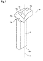
Figur 1 eine Perspektivansicht eines erfindungsgemäßen lichtleitenden Bauteils gemäß einer ersten Ausführungsform, -
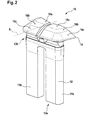
Figur 2 eine Perspektivansicht eines erfindungsgemäßen lichtleitenden Bauteils gemäß einer zweiten Ausführungsform, -
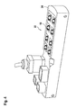
Figur 3 das lichtleitende Bauteil ausFigur 2 aus einer anderen Perspektive, -
Figur 4 ein erfindungsgemäßes Feldbusmodul mit mehreren lichtleitenden Bauteilen, und -
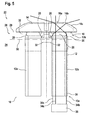
Figur 5 eine schematische Schnittdarstellung durch das Feldbusmodul mit lichtleitendem Bauteil.
-
FIG. 1 a perspective view of a light-conducting component according to the invention according to a first embodiment, -
FIG. 2 a perspective view of a light-conducting component according to the invention according to a second embodiment, -
FIG. 3 the light-conducting componentFIG. 2 from a different perspective, -
FIG. 4 an inventive field bus module with a plurality of light-conducting components, and -
FIG. 5 a schematic sectional view through the field bus module with lichtleitendem component.
In
Der Hauptkörper 12 ist in der gezeigten Ausführungsform aus einem Lichtleitstab gebildet, sodass es sich bei dem Hauptkörper 12 um einen Vollkörper handelt, der vorzugsweise aus einem transparenten Kunststoff gebildet ist. Der Hauptkörper 12 wird über ein erstes Ende 13a einer hier nicht dargestellten Lichtquelle zugeordnet, sodass Licht an diesem ersten Ende 13a in den Hauptkörper 12 einkoppeln kann.The
An einem zweiten Ende 13b des Hauptkörpers 12 ist das Austrittselement 14 angeordnet, an dem das ins lichtleitende Bauteil 10 eingekoppelte Licht wieder auskoppelt. Das Austrittselement 14 weist hierzu mehrere Austrittsflächen 16 auf, wobei eine senkrecht zur Lichtausbreitungsrichtung L des Lichts angeordnete Hauptaustrittsfläche 16a sowie eine erste und eine zweite Nebenaustrittsflächen 16b, 16c vorgesehen sind. Die Nebenaustrittsflächen 16b, 16c sind zur Hauptaustrittsfläche 16a unter einem Winkel angeordnet, wobei die dritte Nebenaustrittsfläche 16c und die zweite Nebenaustrittsfläche 16b ebenfalls einen Winkel einschließen.At a
Insgesamt ergibt sich eine nach außen abfallende Anordnung der Austrittsflächen 16.Overall, an outwardly sloping arrangement of the exit surfaces 16 results.
Die Lichtausbreitungsrichtung L des Lichts im Hauptkörper 12 ist parallel zur Längsachse des Hauptkörpers 12, die analog mit dem Bezugszeichen L bezeichnet werden kann.The light propagation direction L of the light in the
Das Austrittelement 14 ist in der gezeigten Ausführungsform auf die Austrittsflächen 16 reduziert, über die das Licht am Austrittselement 14 tatsächlich austritt, wie nachfolgend noch erläutert wird. Andere Gestaltungen des Austrittselements 14 sind jedoch denkbar, insbesondere solche, die eine größere Gesamtfläche aufweisen, die dann jedoch Teilflächen aufweist, an denen kein Licht austritt.In the embodiment shown, the
In
Das lichtleitende Bauteil 10 gemäß der zweiten Ausführungsform weist einen Hauptkörper 12 auf, der aus zwei Lichtleitstäben 12a, 12b ausgebildet ist. Über ein erstes Ende 13a kann der Hauptkörper 12 zwei Lichtquellen zugeordnet werden, eine Lichtquelle pro Lichtleitstab 12a, 12b.The
Aus der gezeigten Perspektive ist ferner zu erkennen, dass die beiden Lichtleitstäbe 12a, 12b nur teilweise getrennt voneinander ausgebildet sind, da sie am zweiten Ende 13b zusammenlaufen, um so den gemeinsamen Hauptkörper 12 auszubilden.It can further be seen from the perspective shown that the two light-conducting
Analog zur ersten Ausführungsform ist ein Austrittselement 14 am zweiten Ende 13b des Hauptkörpers 12 vorgesehen, welches gegenüber der ersten Ausführungsform jedoch in etwa doppelt so groß ausgebildet ist, sodass es beiden Lichtleitstäben 12a, 12b zugeordnet ist. Das Austrittselement 14 verfügt über eine Hauptaustrittsfläche 16a sowie einer ersten und einer zweiten Nebenaustrittsfläche 16b, 16c pro Lichtleitstab 12a, 12b. Das Austrittselement 14 ist dabei spiegelsymmetrisch zu einer Symmetrieachse S ausgebildet, die das Austrittselement 14 in zwei Hälften unterteilt.Analogous to the first embodiment, an
In
Aus der in
Ferner geht aus der
Das Reflexionselement 20 ist von außen als ein schräger Abschnitt in der Seitenwand des Hauptkörpers 12 ausgebildet, sodass es an die äußere Umgebung des lichtleitenden Bauteils 10 angrenzt. Das Reflexionselement 20 kann über eine Einkerbung im als Vollkörper ausgebildeten Hauptkörper 12 hergestellt sein, die sich schräg zur Längsausrichtung L des Hauptkörpers 12 erstreckt. Das Reflexionselement 20 kann insbesondere durch einen keilförmigen Ausschnitt im Hauptkörper 12 ausgebildet werden.The
Das lichtleitende Bauteil 10 weist generell, das heißt auch in der in
Die Reflexionselemente 20 sind zudem in
In
Das im Feldbusmodul 22 angeordnete lichtleitende Bauteil 10 ist gemäß der zweiten Ausführungsform ausgeführt, sodass der Hauptkörper 12 zwei Lichtleitstäbe 12a, 12b umfasst.The light-conducting
Das lichtleitende Bauteil 10 ist im Gehäuse 24 derart angeordnet, dass es mit seiner Auflagefläche 18 auf der ersten Wand 28 aufliegt, sodass nur das Austrittselement 14 von der Oberfläche des Gehäuses 24 absteht. Die nach außen abfallende Geometrie des Austrittselements 14 geht aus der
Ferner sind die Reflexionselemente 20 aufgrund der Lage des lichtleitenden Bauteils 10 im Bereich des Hohlraums 32 des Feldbusmoduls 22 angeordnet und grenzen direkt an diesen an. Hierdurch ergibt sich ein Brechungsindexsprung zwischen den als Einkerbungen im Vollkörper des Hauptkörpers 12 ausgebildeten Reflexionselementen 20 und dem Hohlraum 32, der mit Luft gefüllt ist.Furthermore, due to the position of the light-conducting
Alternativ kann der Hohlraum 32 mit einem Gas, einem Gasgemisch oder einem sonstigen Material gefüllt sein, durch das sich der Brechungsindexsprung vom Hauptkörper 12 zum Hohlraum 32 ergibt. Der Brechungsindexsprung ist nötig, damit Licht an den Reflexionselementen 20 überhaupt reflektieren kann.Alternatively, the
In der
Die Lichtstrahlen 34 werden von der Lichtquelle 36 parallel zur Längsausrichtung L des lichtleitenden Bauteils 10 und des Hauptkörpers 12 ausgestrahlt, sodass sie senkrecht am ersten Ende 13a in den Hauptkörper 12 einkoppeln und zunächst parallel zur Längsausrichtung L verlaufen.The light beams 34 are radiated from the
Der erste Lichtstrahl 34a verläuft durch den Hauptkörper 12 des lichtleitenden Bauteils 10 und wechselwirkt nicht mit einem der Reflexionselemente 20, sodass er durch das Austrittselement 14 läuft und direkt auf die senkrecht zur Lichtausbreitungsrichtung L angeordnete Hauptaustrittsfläche 16a trifft. Durch diese koppelt der erste Lichtstrahl 34a senkrecht aus. Dieser beispielhafte erste Lichtstrahl 34a wird von einem Benutzer bei frontaler Sicht auf das lichtleitende Bauteil 10 bzw. das Feldbusmodul 22 gesehen.The
Der zweite Lichtstrahl 34b verläuft zunächst parallel zum ersten Lichtstrahl 34a, wobei er im Bereich des Hohlraums 32 des Feldbusmoduls 22 auf eines der Reflexionselemente 20 trifft und aufgrund des Lichtbrechungsindexunterschieds zwischen dem Hauptkörper 12 und dem Hohlraum 32 an dem Reflexionselement 20 reflektiert.The second
Aufgrund der Reflexion tritt der zweite Lichtstrahl 34b unter einem Winkel in das Austrittselement 14 ein und trifft unter einem Winkel auf die Hauptaustrittsfläche 16a. Dies hat zur Folge, dass der zweite Lichtstrahl 34b beim Übergang vom Austrittselement 14 zum Außenbereich erneut gebrochen wird, wodurch sich eine noch größere Streuung des Lichts in Bezug auf die Lichtausbreitungsrichtung L innerhalb des Hauptkörpers 12 ergibt. Der beispielhafte zweite Lichtstrahl 34b koppelt am Austrittselement 14 unter einem Winkel von ca. -75° zur Lichtausbreitungsrichtung L aus.Due to the reflection, the second
Der dritte Lichtstrahl 34c verläuft im Hauptkörper 12 zunächst parallel zu den beiden anderen Lichtstrahlen 34a, 34b, wobei der dritte Lichtstrahl 34c auf ein anderes Reflexionselement 20 trifft, welches ebenfalls dem Hohlraum 32 zugeordnet ist. An diesem Reflexionselement 20 wird der dritte Lichtstrahl 34c reflektiert, wobei die Reflexion aufgrund der gegenüberliegenden Ausrichtung der beiden Reflexionselemente 20 zur anderen Richtung erfolgt im Vergleich zum zweiten Lichtstrahl 34b.The third
Der dritte Lichtstrahl 34c koppelt nach der Reflexion in das Austrittselement 14 unter einem Winkel ein und trifft auf die erste Nebenaustrittsfläche 16b, an der er auskoppelt. Die erste Nebenaustrittsfläche 16b ist, wie oben bereits beschrieben, winklig zur Hauptaustrittsfläche 16a angeordnet. Hierdurch ergibt sich eine weitere Brechung des Lichtstrahls 34c, sodass der Streubereich des Lichts weiter vergrößert ist. Der beispielhafte dritte Lichtstrahl 34c koppelt am Austrittselement 14 unter einem Winkel von ca. +78° zur Lichtausbreitungsrichtung L aus.The third
Die drei Lichtstrahlen 34a - 34c sind lediglich beispielhafte Lichtstrahlen, die das Konzept verdeutlichen sollen. Insgesamt kann aufgrund der Reflexionselemente 20 eine im Wesentlichen isotrope Verteilung der ausgekoppelten Lichtstrahlen in einem Winkelbereich von etwa -90° bis etwa +90° in Bezug zur Lichtausbreitungsrichtung L erreicht werden. Dies bedeutet, dass die am Austrittselement 14 auskoppelenden Lichtstrahlen in der gezeigten Schnittebene einen Halbkreis ausbilden.The three
Die Reflexionselemente 20 sind in Bezug auf die Lichtausbreitungsrichtung L derart angeordnet, dass sie einen Winkel aufweisen, der größer als der Grenzwinkel der Totalreflexion ist, sodass sämtliches auf die Reflexionselemente 20 auftreffende Licht an diesen reflektiert wird. Der Grenzwinkel der Totalreflexion kann dabei über das Medium im Hohlraum 32 eingestellt werden.The
Insgesamt werden mindestens 20% des gesamten von der Lichtquelle 36 ausgesandten Lichts an den Reflexionselementen 20 reflektiert, wobei dies von der Größe der Reflexionselemente 20 abhängig ist. Der Anteil des reflektierten Lichts ist dabei so gewählt, dass eine im Wesentlichen isotrope Verteilung wahrgenommen wird.Overall, at least 20% of the total light emitted by the
Da zwei weitere Reflexionselemente 20 senkrecht zu den in der Zeichenebene gezeigten Reflexionselementen 20 vorgesehen sind, ergeben sich hieraus weitere im Wesentlichen halbkreisförmige isotrope Verteilungen der auskoppelnden Lichtstrahlen.Since two
Die Reflexionselemente 20 können ferner gekrümmt ausgebildet sein, wodurch sich eine Reflexion des Lichts in einem Winkelbereich und nicht nur unter einem festen Winkel ergibt. Hierdurch ist es möglich, dass die Lichtstrahlen am Austrittselement isotrop in einer Halbsphäre austreten, also in einer Halbkugel. Dies gewährleistet, dass das ausgekoppelte Licht sowohl in frontaler als auch in seitlicher Ansicht deutlich zu erkennen ist. Das ausgekoppelte Licht ist demnach aus jedem Blickwinkel der Halbsphäre zu sehen.The
Die Austrittsflächen 16 am Austrittselement 14 können ferner eine Rauigkeit erzeugt durch eine Erodierstruktur Ref. 18 nah VDI 3400 und anschließender Behandlung mit dem Strahlmittel SM 2002A unter einem Arbeitsdruck von 2 Bar haben, so dass das an den Austrittsflächen 16 ausgekoppelte Licht eine homogenere Lichtausbreitung aufweist.The exit surfaces 16 on the
Bei der verwendeten Lichtquelle 36 kann es sich um eine mehrfarbige LED handeln, die derart ausgebildet ist, dass beispielsweise der zweite Lichtstrahl 34b rot und der dritte Lichtstrahl 34c gelb ist, sodass sich insgesamt ein oranges Licht ergibt. Sollte die Streuung unzureichend sein, so ergibt sich bei seitlicher Betrachtung lediglich ein rotes oder gelbes Signal.The
Alternativ kann die mehrfarbige LED auch dazu verwendet werden, um generell zwei bestimmten Zuständen zugeordnete Farben darzustellen, wie rot und grün.Alternatively, the multicolor LED can also be used to represent colors generally associated with two particular states, such as red and green.
Das von der Lichtquelle 36 ausgesandte Licht kann zudem einen in
Mit dem erfindungsgemäßen lichtleitenden Bauteil 10 ergibt sich ein schlankes Design, das bei der Verwendung am Feldbusmodul 22 von Vorteil ist, da keine Schmutzkanten auftreten und die Reflexionselemente 20 von außen nicht sichtbar sind.With the light-conducting
Claims (15)
Applications Claiming Priority (1)
| Application Number | Priority Date | Filing Date | Title |
|---|---|---|---|
| DE102014102697.7A DE102014102697A1 (en) | 2014-02-28 | 2014-02-28 | Fiber-optic component and fieldbus module |
Publications (2)
| Publication Number | Publication Date |
|---|---|
| EP2913698A1 true EP2913698A1 (en) | 2015-09-02 |
| EP2913698B1 EP2913698B1 (en) | 2019-09-18 |
Family
ID=52596776
Family Applications (1)
| Application Number | Title | Priority Date | Filing Date |
|---|---|---|---|
| EP15156382.2A Active EP2913698B1 (en) | 2014-02-28 | 2015-02-24 | Light conducting component and field bus module |
Country Status (2)
| Country | Link |
|---|---|
| EP (1) | EP2913698B1 (en) |
| DE (1) | DE102014102697A1 (en) |
Families Citing this family (1)
| Publication number | Priority date | Publication date | Assignee | Title |
|---|---|---|---|---|
| DE102021130545B3 (en) | 2021-11-23 | 2022-12-29 | Turck Holding Gmbh | Electronic component and method for manufacturing an electronic component |
Citations (4)
| Publication number | Priority date | Publication date | Assignee | Title |
|---|---|---|---|---|
| US5555161A (en) * | 1995-09-11 | 1996-09-10 | Delco Electronics Corporation | Bi-functional light pipe and display assembly |
| US20090086469A1 (en) * | 2007-10-01 | 2009-04-02 | Hon Hai Precision Ind. Co., Ltd. | Electrical connector with illumination waveguide |
| US20100291791A1 (en) * | 2009-05-14 | 2010-11-18 | Hon Hai Precision Industry Co., Ltd. | Cable connector assembly with an improved ring member |
| US20110256757A1 (en) * | 2010-04-15 | 2011-10-20 | Hon Hai Precision Industry Co., Ltd. | Rj-45 connector |
Family Cites Families (7)
| Publication number | Priority date | Publication date | Assignee | Title |
|---|---|---|---|---|
| DE20122415U1 (en) * | 1969-08-25 | 2005-08-18 | Witte & Sutor Gmbh | Plug-in light has light emitting diode threshold voltage not less than product of accumulator discharge voltage and number of accumulator cells |
| DE8509691U1 (en) * | 1985-03-30 | 1988-04-14 | Braun Ag, 6000 Frankfurt, De | |
| US20090051558A1 (en) * | 2007-08-20 | 2009-02-26 | Tellabs Bedford, Inc. | Method and apparatus for providing optical indications about a state of a circuit |
| EP2039985B1 (en) * | 2007-09-20 | 2017-10-25 | Siteco Beleuchtungstechnik GmbH | LED lighting device with asymmetric light distribution, in particular for street lighting |
| EP2101202A1 (en) * | 2008-03-10 | 2009-09-16 | Basta France | Light signalling device for a cycle |
| US8813676B2 (en) * | 2010-05-07 | 2014-08-26 | Whirlpool Corporation | User interface for a controller |
| DE102010047903A1 (en) * | 2010-10-11 | 2012-04-12 | Motogadget Gmbh | Lamp for a vehicle |
-
2014
- 2014-02-28 DE DE102014102697.7A patent/DE102014102697A1/en not_active Withdrawn
-
2015
- 2015-02-24 EP EP15156382.2A patent/EP2913698B1/en active Active
Patent Citations (4)
| Publication number | Priority date | Publication date | Assignee | Title |
|---|---|---|---|---|
| US5555161A (en) * | 1995-09-11 | 1996-09-10 | Delco Electronics Corporation | Bi-functional light pipe and display assembly |
| US20090086469A1 (en) * | 2007-10-01 | 2009-04-02 | Hon Hai Precision Ind. Co., Ltd. | Electrical connector with illumination waveguide |
| US20100291791A1 (en) * | 2009-05-14 | 2010-11-18 | Hon Hai Precision Industry Co., Ltd. | Cable connector assembly with an improved ring member |
| US20110256757A1 (en) * | 2010-04-15 | 2011-10-20 | Hon Hai Precision Industry Co., Ltd. | Rj-45 connector |
Also Published As
| Publication number | Publication date |
|---|---|
| DE102014102697A1 (en) | 2015-09-03 |
| EP2913698B1 (en) | 2019-09-18 |
Similar Documents
| Publication | Publication Date | Title |
|---|---|---|
| DE102016100207B4 (en) | Signal light | |
| AT518118B1 (en) | Lighting unit for a motor vehicle | |
| EP2530503A1 (en) | Illumination device | |
| DE102009052339A1 (en) | Lighting device for a motor vehicle | |
| AT517105B1 (en) | Optical fiber arrangement for generating at least one illumination function and / or signaling function of a motor vehicle headlight | |
| DE202016008339U1 (en) | Optical fiber arrangement for generating at least one illumination function and / or signaling function of a motor vehicle headlight | |
| EP2500753B1 (en) | Optical fibre with decoupling elements which decouple light directly | |
| EP3531012A1 (en) | Lighting device for motor vehicles with a rod-like light guide | |
| EP2618045A1 (en) | Lighting device for a motor vehicle | |
| EP3158260B1 (en) | Motor vehicle lighting device | |
| DE102013110839A1 (en) | Lighting device for vehicles | |
| DE102004054732A1 (en) | Optical fiber arrangement for external rear view mirror of vehicle, has stretched optical fiber rod that is approximately parallel to edge of plate shaped optical fiber, and light source connected to front end of optical fiber rod | |
| EP3899358B1 (en) | Lighting device for a motor vehicle headlamp and motor vehicle headlamp | |
| DE102005059958A1 (en) | lighting device | |
| EP2927572A1 (en) | Light for motor vehicle comprising a wipe effect | |
| DE102012209337A1 (en) | Light guide and light guide device | |
| DE102011090197B4 (en) | Light guide for a motor vehicle lighting device | |
| EP1832902A1 (en) | Flat lamp device | |
| DE102017108545A1 (en) | Luminaire for a motor vehicle body | |
| EP3812653B1 (en) | Signal light with a light guide | |
| EP2787276A1 (en) | Fibre optic assembly having two fibre optic elements | |
| EP2913698B1 (en) | Light conducting component and field bus module | |
| DE102018120799A1 (en) | An optical system of a direction indicator for motor vehicles, in particular a progressive direction indicator | |
| EP3212997B1 (en) | Optical element and a light-emitting arrangement which comprises an optical element | |
| DE102013209473B4 (en) | optical fiber |
Legal Events
| Date | Code | Title | Description |
|---|---|---|---|
| PUAI | Public reference made under article 153(3) epc to a published international application that has entered the european phase |
Free format text: ORIGINAL CODE: 0009012 |
|
| AK | Designated contracting states |
Kind code of ref document: A1 Designated state(s): AL AT BE BG CH CY CZ DE DK EE ES FI FR GB GR HR HU IE IS IT LI LT LU LV MC MK MT NL NO PL PT RO RS SE SI SK SM TR |
|
| AX | Request for extension of the european patent |
Extension state: BA ME |
|
| 17P | Request for examination filed |
Effective date: 20160217 |
|
| RBV | Designated contracting states (corrected) |
Designated state(s): AL AT BE BG CH CY CZ DE DK EE ES FI FR GB GR HR HU IE IS IT LI LT LU LV MC MK MT NL NO PL PT RO RS SE SI SK SM TR |
|
| GRAP | Despatch of communication of intention to grant a patent |
Free format text: ORIGINAL CODE: EPIDOSNIGR1 |
|
| STAA | Information on the status of an ep patent application or granted ep patent |
Free format text: STATUS: GRANT OF PATENT IS INTENDED |
|
| INTG | Intention to grant announced |
Effective date: 20190409 |
|
| GRAS | Grant fee paid |
Free format text: ORIGINAL CODE: EPIDOSNIGR3 |
|
| GRAA | (expected) grant |
Free format text: ORIGINAL CODE: 0009210 |
|
| STAA | Information on the status of an ep patent application or granted ep patent |
Free format text: STATUS: THE PATENT HAS BEEN GRANTED |
|
| AK | Designated contracting states |
Kind code of ref document: B1 Designated state(s): AL AT BE BG CH CY CZ DE DK EE ES FI FR GB GR HR HU IE IS IT LI LT LU LV MC MK MT NL NO PL PT RO RS SE SI SK SM TR |
|
| REG | Reference to a national code |
Ref country code: GB Ref legal event code: FG4D Free format text: NOT ENGLISH |
|
| REG | Reference to a national code |
Ref country code: CH Ref legal event code: EP |
|
| REG | Reference to a national code |
Ref country code: DE Ref legal event code: R096 Ref document number: 502015010372 Country of ref document: DE |
|
| REG | Reference to a national code |
Ref country code: AT Ref legal event code: REF Ref document number: 1182014 Country of ref document: AT Kind code of ref document: T Effective date: 20191015 |
|
| REG | Reference to a national code |
Ref country code: IE Ref legal event code: FG4D Free format text: LANGUAGE OF EP DOCUMENT: GERMAN |
|
| REG | Reference to a national code |
Ref country code: NL Ref legal event code: MP Effective date: 20190918 |
|
| PG25 | Lapsed in a contracting state [announced via postgrant information from national office to epo] |
Ref country code: SE Free format text: LAPSE BECAUSE OF FAILURE TO SUBMIT A TRANSLATION OF THE DESCRIPTION OR TO PAY THE FEE WITHIN THE PRESCRIBED TIME-LIMIT Effective date: 20190918 Ref country code: LT Free format text: LAPSE BECAUSE OF FAILURE TO SUBMIT A TRANSLATION OF THE DESCRIPTION OR TO PAY THE FEE WITHIN THE PRESCRIBED TIME-LIMIT Effective date: 20190918 Ref country code: BG Free format text: LAPSE BECAUSE OF FAILURE TO SUBMIT A TRANSLATION OF THE DESCRIPTION OR TO PAY THE FEE WITHIN THE PRESCRIBED TIME-LIMIT Effective date: 20191218 Ref country code: NO Free format text: LAPSE BECAUSE OF FAILURE TO SUBMIT A TRANSLATION OF THE DESCRIPTION OR TO PAY THE FEE WITHIN THE PRESCRIBED TIME-LIMIT Effective date: 20191218 Ref country code: FI Free format text: LAPSE BECAUSE OF FAILURE TO SUBMIT A TRANSLATION OF THE DESCRIPTION OR TO PAY THE FEE WITHIN THE PRESCRIBED TIME-LIMIT Effective date: 20190918 Ref country code: HR Free format text: LAPSE BECAUSE OF FAILURE TO SUBMIT A TRANSLATION OF THE DESCRIPTION OR TO PAY THE FEE WITHIN THE PRESCRIBED TIME-LIMIT Effective date: 20190918 |
|
| REG | Reference to a national code |
Ref country code: LT Ref legal event code: MG4D |
|
| PG25 | Lapsed in a contracting state [announced via postgrant information from national office to epo] |
Ref country code: LV Free format text: LAPSE BECAUSE OF FAILURE TO SUBMIT A TRANSLATION OF THE DESCRIPTION OR TO PAY THE FEE WITHIN THE PRESCRIBED TIME-LIMIT Effective date: 20190918 Ref country code: AL Free format text: LAPSE BECAUSE OF FAILURE TO SUBMIT A TRANSLATION OF THE DESCRIPTION OR TO PAY THE FEE WITHIN THE PRESCRIBED TIME-LIMIT Effective date: 20190918 Ref country code: GR Free format text: LAPSE BECAUSE OF FAILURE TO SUBMIT A TRANSLATION OF THE DESCRIPTION OR TO PAY THE FEE WITHIN THE PRESCRIBED TIME-LIMIT Effective date: 20191219 Ref country code: RS Free format text: LAPSE BECAUSE OF FAILURE TO SUBMIT A TRANSLATION OF THE DESCRIPTION OR TO PAY THE FEE WITHIN THE PRESCRIBED TIME-LIMIT Effective date: 20190918 |
|
| PG25 | Lapsed in a contracting state [announced via postgrant information from national office to epo] |
Ref country code: ES Free format text: LAPSE BECAUSE OF FAILURE TO SUBMIT A TRANSLATION OF THE DESCRIPTION OR TO PAY THE FEE WITHIN THE PRESCRIBED TIME-LIMIT Effective date: 20190918 Ref country code: PT Free format text: LAPSE BECAUSE OF FAILURE TO SUBMIT A TRANSLATION OF THE DESCRIPTION OR TO PAY THE FEE WITHIN THE PRESCRIBED TIME-LIMIT Effective date: 20200120 Ref country code: PL Free format text: LAPSE BECAUSE OF FAILURE TO SUBMIT A TRANSLATION OF THE DESCRIPTION OR TO PAY THE FEE WITHIN THE PRESCRIBED TIME-LIMIT Effective date: 20190918 Ref country code: EE Free format text: LAPSE BECAUSE OF FAILURE TO SUBMIT A TRANSLATION OF THE DESCRIPTION OR TO PAY THE FEE WITHIN THE PRESCRIBED TIME-LIMIT Effective date: 20190918 Ref country code: NL Free format text: LAPSE BECAUSE OF FAILURE TO SUBMIT A TRANSLATION OF THE DESCRIPTION OR TO PAY THE FEE WITHIN THE PRESCRIBED TIME-LIMIT Effective date: 20190918 Ref country code: RO Free format text: LAPSE BECAUSE OF FAILURE TO SUBMIT A TRANSLATION OF THE DESCRIPTION OR TO PAY THE FEE WITHIN THE PRESCRIBED TIME-LIMIT Effective date: 20190918 |
|
| PG25 | Lapsed in a contracting state [announced via postgrant information from national office to epo] |
Ref country code: CZ Free format text: LAPSE BECAUSE OF FAILURE TO SUBMIT A TRANSLATION OF THE DESCRIPTION OR TO PAY THE FEE WITHIN THE PRESCRIBED TIME-LIMIT Effective date: 20190918 Ref country code: SK Free format text: LAPSE BECAUSE OF FAILURE TO SUBMIT A TRANSLATION OF THE DESCRIPTION OR TO PAY THE FEE WITHIN THE PRESCRIBED TIME-LIMIT Effective date: 20190918 Ref country code: SM Free format text: LAPSE BECAUSE OF FAILURE TO SUBMIT A TRANSLATION OF THE DESCRIPTION OR TO PAY THE FEE WITHIN THE PRESCRIBED TIME-LIMIT Effective date: 20190918 Ref country code: IS Free format text: LAPSE BECAUSE OF FAILURE TO SUBMIT A TRANSLATION OF THE DESCRIPTION OR TO PAY THE FEE WITHIN THE PRESCRIBED TIME-LIMIT Effective date: 20200224 |
|
| REG | Reference to a national code |
Ref country code: DE Ref legal event code: R097 Ref document number: 502015010372 Country of ref document: DE |
|
| PLBE | No opposition filed within time limit |
Free format text: ORIGINAL CODE: 0009261 |
|
| STAA | Information on the status of an ep patent application or granted ep patent |
Free format text: STATUS: NO OPPOSITION FILED WITHIN TIME LIMIT |
|
| PG2D | Information on lapse in contracting state deleted |
Ref country code: IS |
|
| PG25 | Lapsed in a contracting state [announced via postgrant information from national office to epo] |
Ref country code: DK Free format text: LAPSE BECAUSE OF FAILURE TO SUBMIT A TRANSLATION OF THE DESCRIPTION OR TO PAY THE FEE WITHIN THE PRESCRIBED TIME-LIMIT Effective date: 20190918 Ref country code: IS Free format text: LAPSE BECAUSE OF FAILURE TO SUBMIT A TRANSLATION OF THE DESCRIPTION OR TO PAY THE FEE WITHIN THE PRESCRIBED TIME-LIMIT Effective date: 20200119 |
|
| 26N | No opposition filed |
Effective date: 20200619 |
|
| PG25 | Lapsed in a contracting state [announced via postgrant information from national office to epo] |
Ref country code: SI Free format text: LAPSE BECAUSE OF FAILURE TO SUBMIT A TRANSLATION OF THE DESCRIPTION OR TO PAY THE FEE WITHIN THE PRESCRIBED TIME-LIMIT Effective date: 20190918 |
|
| REG | Reference to a national code |
Ref country code: BE Ref legal event code: MM Effective date: 20200229 |
|
| PG25 | Lapsed in a contracting state [announced via postgrant information from national office to epo] |
Ref country code: MC Free format text: LAPSE BECAUSE OF FAILURE TO SUBMIT A TRANSLATION OF THE DESCRIPTION OR TO PAY THE FEE WITHIN THE PRESCRIBED TIME-LIMIT Effective date: 20190918 Ref country code: LU Free format text: LAPSE BECAUSE OF NON-PAYMENT OF DUE FEES Effective date: 20200224 |
|
| PG25 | Lapsed in a contracting state [announced via postgrant information from national office to epo] |
Ref country code: IE Free format text: LAPSE BECAUSE OF NON-PAYMENT OF DUE FEES Effective date: 20200224 |
|
| PG25 | Lapsed in a contracting state [announced via postgrant information from national office to epo] |
Ref country code: BE Free format text: LAPSE BECAUSE OF NON-PAYMENT OF DUE FEES Effective date: 20200229 |
|
| REG | Reference to a national code |
Ref country code: AT Ref legal event code: MM01 Ref document number: 1182014 Country of ref document: AT Kind code of ref document: T Effective date: 20200224 |
|
| PG25 | Lapsed in a contracting state [announced via postgrant information from national office to epo] |
Ref country code: AT Free format text: LAPSE BECAUSE OF NON-PAYMENT OF DUE FEES Effective date: 20200224 |
|
| PGFP | Annual fee paid to national office [announced via postgrant information from national office to epo] |
Ref country code: GB Payment date: 20220223 Year of fee payment: 8 Ref country code: DE Payment date: 20220222 Year of fee payment: 8 Ref country code: CH Payment date: 20220216 Year of fee payment: 8 |
|
| PG25 | Lapsed in a contracting state [announced via postgrant information from national office to epo] |
Ref country code: TR Free format text: LAPSE BECAUSE OF FAILURE TO SUBMIT A TRANSLATION OF THE DESCRIPTION OR TO PAY THE FEE WITHIN THE PRESCRIBED TIME-LIMIT Effective date: 20190918 Ref country code: MT Free format text: LAPSE BECAUSE OF FAILURE TO SUBMIT A TRANSLATION OF THE DESCRIPTION OR TO PAY THE FEE WITHIN THE PRESCRIBED TIME-LIMIT Effective date: 20190918 Ref country code: CY Free format text: LAPSE BECAUSE OF FAILURE TO SUBMIT A TRANSLATION OF THE DESCRIPTION OR TO PAY THE FEE WITHIN THE PRESCRIBED TIME-LIMIT Effective date: 20190918 |
|
| PGFP | Annual fee paid to national office [announced via postgrant information from national office to epo] |
Ref country code: IT Payment date: 20220218 Year of fee payment: 8 Ref country code: FR Payment date: 20220216 Year of fee payment: 8 |
|
| PG25 | Lapsed in a contracting state [announced via postgrant information from national office to epo] |
Ref country code: MK Free format text: LAPSE BECAUSE OF FAILURE TO SUBMIT A TRANSLATION OF THE DESCRIPTION OR TO PAY THE FEE WITHIN THE PRESCRIBED TIME-LIMIT Effective date: 20190918 |
|
| REG | Reference to a national code |
Ref country code: DE Ref legal event code: R119 Ref document number: 502015010372 Country of ref document: DE |
|
| REG | Reference to a national code |
Ref country code: CH Ref legal event code: PL |
|
| GBPC | Gb: european patent ceased through non-payment of renewal fee |
Effective date: 20230224 |
|
| PG25 | Lapsed in a contracting state [announced via postgrant information from national office to epo] |
Ref country code: LI Free format text: LAPSE BECAUSE OF NON-PAYMENT OF DUE FEES Effective date: 20230228 Ref country code: CH Free format text: LAPSE BECAUSE OF NON-PAYMENT OF DUE FEES Effective date: 20230228 |
|
| PG25 | Lapsed in a contracting state [announced via postgrant information from national office to epo] |
Ref country code: GB Free format text: LAPSE BECAUSE OF NON-PAYMENT OF DUE FEES Effective date: 20230224 |
|
| PG25 | Lapsed in a contracting state [announced via postgrant information from national office to epo] |
Ref country code: IT Free format text: LAPSE BECAUSE OF NON-PAYMENT OF DUE FEES Effective date: 20230224 Ref country code: GB Free format text: LAPSE BECAUSE OF NON-PAYMENT OF DUE FEES Effective date: 20230224 Ref country code: FR Free format text: LAPSE BECAUSE OF NON-PAYMENT OF DUE FEES Effective date: 20230228 Ref country code: DE Free format text: LAPSE BECAUSE OF NON-PAYMENT OF DUE FEES Effective date: 20230901 |