EP2913652A1 - Method for monitoring and/or locating fluid losses in a pipe network - Google Patents
Method for monitoring and/or locating fluid losses in a pipe network Download PDFInfo
- Publication number
- EP2913652A1 EP2913652A1 EP15163403.7A EP15163403A EP2913652A1 EP 2913652 A1 EP2913652 A1 EP 2913652A1 EP 15163403 A EP15163403 A EP 15163403A EP 2913652 A1 EP2913652 A1 EP 2913652A1
- Authority
- EP
- European Patent Office
- Prior art keywords
- data
- measuring
- flow
- network
- measurement
- Prior art date
- Legal status (The legal status is an assumption and is not a legal conclusion. Google has not performed a legal analysis and makes no representation as to the accuracy of the status listed.)
- Granted
Links
Images
Classifications
-
- G—PHYSICS
- G01—MEASURING; TESTING
- G01F—MEASURING VOLUME, VOLUME FLOW, MASS FLOW OR LIQUID LEVEL; METERING BY VOLUME
- G01F1/00—Measuring the volume flow or mass flow of fluid or fluent solid material wherein the fluid passes through a meter in a continuous flow
- G01F1/66—Measuring the volume flow or mass flow of fluid or fluent solid material wherein the fluid passes through a meter in a continuous flow by measuring frequency, phase shift or propagation time of electromagnetic or other waves, e.g. using ultrasonic flowmeters
- G01F1/667—Arrangements of transducers for ultrasonic flowmeters; Circuits for operating ultrasonic flowmeters
-
- G—PHYSICS
- G01—MEASURING; TESTING
- G01M—TESTING STATIC OR DYNAMIC BALANCE OF MACHINES OR STRUCTURES; TESTING OF STRUCTURES OR APPARATUS, NOT OTHERWISE PROVIDED FOR
- G01M3/00—Investigating fluid-tightness of structures
- G01M3/02—Investigating fluid-tightness of structures by using fluid or vacuum
- G01M3/04—Investigating fluid-tightness of structures by using fluid or vacuum by detecting the presence of fluid at the leakage point
- G01M3/24—Investigating fluid-tightness of structures by using fluid or vacuum by detecting the presence of fluid at the leakage point using infrasonic, sonic, or ultrasonic vibrations
- G01M3/243—Investigating fluid-tightness of structures by using fluid or vacuum by detecting the presence of fluid at the leakage point using infrasonic, sonic, or ultrasonic vibrations for pipes
Definitions
- the invention relates to a method for monitoring and / or location of water losses in a water pipeline network with multiple hydrographs, which is particularly suitable for use in distribution networks of drinking water supply.
- control points are set up at which the flow properties can be recorded simultaneously and in each case over a certain short time for the entire line system regularly and simultaneously.
- a specially designated control shaft is to be produced, whereby the existing lines must be interrupted in order to use slides, measuring devices or water meters can. Subsequent equipment of a water supply system with such a device is therefore not possible.
- the DE 19819258 C2 describes a method for making measurements for the detection of water losses and the location of leaks in water supply systems using probes that perform at regular or irregular intervals or constantly measuring the flow, the pressure and the flow noise at measuring points.
- the analysis is carried out by means of an evaluation on the basis of zero consumption and data on the water pressure, the flow noise as well as the flow rate and the flow direction for locating a leak.
- the measuring elements of the measuring probe used in this case are inserted into a sleeve-like threaded spindle, said threaded spindle is screwed or screwed into a tapping point.
- the known methods or systems have the disadvantages that holes or cuts in the pipes are required, a cross-sectional constriction occurs at the installation sites and a wear and maintenance-free measurement is not possible or only to a limited extent.
- the object of the present invention was thus to provide a method which enables an efficient monitoring of a pipeline network, wherein a reliable and timely detection of leaks, a simple installation under operating conditions, a central analysis of the data and a non-invasive installation on pipelines Pipe material allows.
- the sensors may be juxtaposed at a distance from each other on the same side of the tube or mounted offset on opposite sides of the tube.
- the inventive method can be used in particular to monitor and / or locate water losses in a drinking water pipeline network.
- the method can assist a pipe network operator in monitoring the distribution network for pipe bursts and other leaks.
- the measured data of the hydrographs with the characteristic minimum night are evaluated in the central computer unit, wherein the hydrographs to the minimum measured Values are averaged out, which are averaged, preferably five, lowest values and the water movements thus identified during the low-consumption night hours indicate leakage.
- statements about the network state and / or its changes can take place and / or a quantification of the leakage quantities can be carried out by comparing the measurement data of the individual measurement units and / or data derived therefrom with measurement data recorded in the past.
- the transmission of the measured data from the data transmission module of the individual measuring units to a central computer unit preferably takes place via a public mobile radio network, for example GSM.
- the data transmission module is preferably a GSM modem with antenna.
- the location of a leak can be localized particularly advantageous to a portion of the pipe network locally by measuring data from adjacent measuring units are evaluated together.
- the measuring units are preferably mounted in the piping system at a distance of 5 to 20 kilometers from each other and the flow rate in the pipe is permanently measured. Every second, a measured value is stored.
- the minimum and maximum liquid flow and an average value determined in each case from the measured data of the measuring units In a computer unit at the measuring unit, the volume flows are calculated and sent as compressed, provided with a time stamp data packets in SMS format to the central computer unit according to an advantageous embodiment. Furthermore, all data SMS can be routed to a receiving center or the central collection and processing of data and / or the retrieval of events via the Internet connection.
- a first stage comprising the above identification and coarse location of a fluid loss in the pipeline network
- a second stage in which a further local containment of a leak by means of a surface noise level measurement in the potential leak area designated part of the pipeline network.
- the location of the leak in the largely limited network area can be carried out with further methods of leak location, preferably correlation.
- the inventive method can be carried out particularly advantageous in a three-stage approach:
- the first stage represents the permanent loss monitoring of the overall network by automated systems. These include the container outlet measurements and possibly installed in the distribution network zoneblood measurements.
- the existing measuring network is compacted by the installation of the measuring units according to the invention.
- the monitoring thus provided provides a daily updated overview of the network status and any changes that may occur.
- this monitoring system can provide information on the occurrence of individual leaks, leak size and position with limited accuracy, depending on the density of the measuring devices.
- the result of this first stage is the early identification of a leakage in the distribution network and a rough pre-location of the leak on individual network areas.
- additional measures can be taken to further limit the leakage, such as the areal noise level measurement.
- the result of the second stage is a further limitation of the leakage position.
- the location of the leak in the largely limited network area is now carried out using conventional leak detection methods, such as correlation. This is followed by the repair of the leakage.
- the sequential sequence of these three sub-steps lies among other things in the different costs that their application causes or justifies.
- the specific costs of using the three methods are increasing significantly. By restricting expensive procedures to relevant network areas as much as possible, operating expenses can be significantly reduced. Besides a significant acceleration of the leak identification is possible.
- the flow measurement is carried out in the ultrasonic measurement method by evaluating the transit time differences of two opposite running through the medium ultrasonic signals. During installation, the attachment of the sensor heads adjacent to the outside of the tube in fighter mode is at the fighter level.
- the ultrasonic flow measurement can be used on all pipe materials used in the drinking water supply, such as gray cast iron, ductile iron, steel, plastics (PE, PEh, PEX, PVC) or asbestos cement, also for externally coated or internally lined pipes.
- the method can be used for pipe dimensions with outside diameters from 90 mm to 330 mm, but also larger pipe dimensions can be monitored when using correspondingly powerful sensor heads.
- the method is particularly suitable for reliably detecting low flow rates.
- the measuring threshold of the system is less than 2 cm / s. This enables a high-quality monitoring of the night flows in selected measuring positions in the distribution network. Even small amounts of water loss are displayed. This allows the detection of leaks early after their emergence. A significant shortening of the leakage time is made possible.
- a measured value is stored once a second when determining the flow velocity.
- the flowmeter determines the minimum and maximum flow rate and an average value in freely adjustable measuring intervals.
- the operation of the measuring units can be limited to about one to two hours a day.
- the period of time between 02.00 and 05.00 has proven to be suitable for measuring time.
- the data transmission preferably takes place via the GSM network (mobile radio).
- the internally calculated volume flows are compressed into data packets and sent in SMS format.
- Each SMS contains up to 20 data lines. These are each provided with a time stamp. They contain the minimum and maximum values that occurred in the set measuring interval as well as the mean value.
- the averaging intervals are freely adjustable from one minute to 60 minutes.
- the measuring unit can also be parameterised via remote data transmission.
- the measuring interval can be changed via remote setting.
- Data transmission via SMS is very reliable.
- the individual SMS will be also cached by the provider, if the receiving center is busy by the shipments of other units.
- the receiving center sends an SMS every day, independent of the remaining traffic.
- All data SMS are sent to a receiving center.
- the central collection and processing of data and the retrieval of results via the Internet connection is possible.
- the information is stored in a database.
- a computer program which carries out one or more of the above-mentioned method steps is likewise an object of the invention.
- the computer program is preferably stored on a data carrier.
- a computer system on which a computer program according to the invention is loaded the subject of the invention.
- the computer system can be the central computer unit and / or a computer unit located in the immediate vicinity of the measuring unit.
- the computer program evaluates the data according to the method described above and displays the results graphically. Of particular interest is the identification of the minimally determined flow at the measuring point. Therefore, the data sets are systematically examined for minimum values. Outliers are identified and excluded from the calculation.
- the computer program enables the detailed evaluation of individual measuring points both on the basis of the calculated night minimums and on the basis of the recorded sections of the hydrographs. These are displayed as a set of curves of the three measurement evaluations (maximum and minimum value and mean value in the measurement interval).
- the program enables the comparison of neighboring measuring units.
- the simultaneous display of the measurement series allows a quick overview of the changes of the individual measurement positions against each other.
- several measuring points can be summarized "balance sheet". This creates a zone monitoring.
- the number of measuring points required depends on the desired statement quality of the monitoring system, the network structure, in particular the degree of meshing and the distribution of the pipe dimensions, as well as the possibility of the formation of rigid panning (static zone separation).
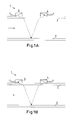
- a measuring unit 1 is positioned at a selected location of a pipe 2 of a pipeline network.
- a measuring unit 1 each of a first sensor 3 and a second sensor 4, which are in the illustrated embodiment along the tube axis side by side spaced mounted on the outside of the tube 2. Both sensors work either as transmitters or as receivers.
- the flow of water through the pipe 2 is determined by the ultrasonic measuring method.
- ultrasonic signals from the sensor 3 according to Fig. 1A emitted, which are reflected on the opposite side of the tube and received by the second sensor 4 again. This first ultrasonic pulse is transmitted in the direction of flow, which is indicated by the arrow, through the liquid.
- a second ultrasonic pulse is sent against the flow direction of the second sensor 4 and detected by the first sensor 3 after reflection on the opposite pipe inner wall. Since the medium in which the ultrasound propagates flows, the transit time of the sound signals which flow through the medium in the direction of flow is shorter than the transit time of the signals which travel counter to the direction of flow. The transit time difference .DELTA.t is measured and allows the determination of the average flow velocity on the sound traversed path. By a profile correction, the surface mean of the flow rate can be calculated which is proportional to the volume flow.
- the distance between the sensors can be, for example, five centimeters.
- minimum and maximum flow limits can be set, which, if exceeded or undershot, automatically generate an alarm signal.
- the volumetric flows calculated in one of the measuring units are transmitted to a central computer unit with the aid of a GSM module.
- the measuring units can be assigned to a control cabinet, wherein at least the GSM module is located. Furthermore, in this cabinet, a PLC control unit (programmable logic controller) with digital input and output terminals and analog input terminal, a mode selector switch (on, off, commissioning), a power supply, a flow meter, a power connector, UPS (an uninterruptible power supply) and a Battery pack be accommodated for bridging voltage-free times.
- the power supply can also be provided by a solar panel (solar module, photovoltaic module or solar generator) or by night-time lighting through the street lighting. In the latter option, batteries are charged at night via a connection to a street lamp.
Abstract
Es wird ein Verfahren zur Überwachung und/oder Ortung von Wasserverlusten in einem Wasserrohrleitungsnetz mit mehreren Ganglinien beschrieben, umfassend mindestens folgende Schritte: - Positionierung von Messeinheiten an ausgewählten Stellen des Rohrleitungsnetzes, wobei eine Messeinheit jeweils aus zwei gleichzeitig als Sender und Empfänger arbeitenden Sensoren besteht, welche entlang der Rohrachse auf der Außenseite, vorzugsweise auf Kämpferhöhe, eines Rohres angebracht sind. - Messung der Strömungsgeschwindigkeit der Flüssigkeit im Rohr mit Hilfe des Ultraschallmessverfahrens, wobei ein erster Ultraschallimpuls durch die Flüssigkeit in Strömungsrichtung sowie ein zweiter Ultraschallimpuls entgegen der Strömungsrichtung gesendet wird, die Sensoren abwechselnd als Sender und Empfänger arbeiten und die Strömungsgeschwindigkeit aus der Laufzeitdifferenz ”t der Schallsignale in Strömungsrichtung bestimmt wird, - Übertragung der Messdaten an eine Datenbank einer zentralen Rechnereinheit mit Hilfe eines an die jeweilige Messeinheit angeschlossenen Datenübertragungsmoduls und, - Auswertung der Messdaten in der zentralen Rechnereinheit, indem die Messdaten der Ganglinien mit dem charakteristischen Nachtminimum ausgewertet werden, wobei die Ganglinien auf die minimal gemessenen Werte hin untersucht werden, die, vorzugsweise fünf, geringsten Werte gemittelt werden und die so identifizierten Wasserbewegungen während der verbrauchsschwachen Nachtstunden auf Leckverluste hinweisen.A method for monitoring and / or locating water losses in a multi-flow water pipe network is described, comprising at least the following steps: - Positioning of measuring units at selected points of the pipeline network, wherein a measuring unit each consisting of two simultaneously working as a transmitter and receiver sensors, which are mounted along the tube axis on the outside, preferably at the fighter level of a tube. - Measurement of the flow velocity of the liquid in the tube by means of the ultrasonic measurement method, wherein a first ultrasonic pulse is sent through the liquid in the flow direction and a second ultrasonic pulse counter to the flow direction, the sensors operate alternately as a transmitter and receiver and the flow velocity of the transit time difference "t of the sound signals is determined in the flow direction, Transmission of the measured data to a database of a central computer unit with the aid of a data transmission module connected to the respective measuring unit and, - Evaluation of the measured data in the central computer unit by the measured data of the hydrographs are evaluated with the characteristic night minimum, wherein the hydrographs are examined for the minimum measured values, which are averaged, preferably five, lowest values and the water movements thus identified during the low-consumption Night hours to indicate leakage.
Description
Die Erfindung betrifft ein Verfahren zur Überwachung und/oder Ortung von Wasserverlusten in einem Wasserrohrleitungsnetz mit mehreren Ganglinien, welches insbesondere zum Einsatz in Verteilnetzen der Trinkwasserversorgung geeignet ist.The invention relates to a method for monitoring and / or location of water losses in a water pipeline network with multiple hydrographs, which is particularly suitable for use in distribution networks of drinking water supply.
Durch Rohrbrüche oder undichte Abschnitte in Flüssigkeitsleitungen, insbesondere Wasserleitungen, oder im Bereich der Endverbraucher können erhebliche Verluste auftreten. Da die Rohrleitungen der Wasserversorgungsnetze unterirdisch verlegt sind, können die Leckverluste nicht ohne Weiteres sofort identifiziert werden.Through pipe breaks or leaking sections in fluid lines, especially water pipes, or in the field of end users significant losses can occur. Since the pipelines of the water supply networks are laid underground, the leakage can not be readily identified immediately.
Aus der
Die
Die bekannten Verfahren bzw. Systeme haben die Nachteile, dass Bohrungen oder Schnitte in die Rohrleitungen erforderlich sind, eine Querschnittsverengung an den Einbaustellen auftritt und eine verschleiß- und wartungsfreie Messung nicht oder nur eingeschränkt möglich ist.The known methods or systems have the disadvantages that holes or cuts in the pipes are required, a cross-sectional constriction occurs at the installation sites and a wear and maintenance-free measurement is not possible or only to a limited extent.
Die Aufgabe der vorliegenden Erfindung bestand somit darin, ein Verfahren bereitzustellen, das eine effiziente Überwachung eines Rohrleitungsnetzes ermöglicht, wobei eine zuverlässige und zeitnahe Detektion von Leckstellen, eine einfache Installation unter Betriebsbedingungen, eine zentrale Auswertung der Daten sowie eine nicht invasive Installation an Rohrleitungen unabhängig vom Rohrmaterial ermöglicht.The object of the present invention was thus to provide a method which enables an efficient monitoring of a pipeline network, wherein a reliable and timely detection of leaks, a simple installation under operating conditions, a central analysis of the data and a non-invasive installation on pipelines Pipe material allows.
Die Aufgabe wurde durch ein Verfahren zur Überwachung und/oder Ortung von Wasserverlusten in einem Wasserrohrleitungsnetz mit mehreren Ganglinien gelöst, wobei das Verfahren mindestens folgende Schritte umfasst:
- Positionierung von Messeinheiten an ausgewählten Stellen des Rohrleitungsnetzes, wobei eine Messeinheit jeweils aus zwei gleichzeitig als Sender und Empfänger arbeitenden Sensoren besteht, welche entlang der Rohrachse auf der Außenseite, vorzugsweise auf Kämpferhöhe, eines Rohres angebracht sind,
- Messung der Strömungsgeschwindigkeit der Flüssigkeit im Rohr mit Hilfe des Ultraschallmessverfahrens, wobei ein erster Ultraschallimpuls durch die Flüssigkeit in Strömungsrichtung sowie ein zweiter Ultraschallimpuls entgegen der Strömungsrichtung gesendet wird, die Sensoren abwechselnd als Sender und Empfänger arbeiten und die Strömungsgeschwindigkeit aus der Laufzeitdifferenz Δt der Schallsignale in Strömungsrichtung und der Schallsignale entgegen der Strömungsrichtung bestimmt wird,
- Übertragung der Messdaten an eine Datenbank einer zentralen Rechnereinheit mit Hilfe eines an die jeweilige Messeinheit angeschlossenen Datenübertragungsmoduls und,
- Auswertung der Messdaten in der zentralen Rechnereinheit, indem die Messdaten der Ganglinien mit dem charakteristischen Nachtminimum ausgewertet werden, wobei die Ganglinien auf die minimal gemessenen Werte hin untersucht werden, die, vorzugsweise fünf, geringsten Werte gemittelt werden und die so identifizierten Wasserbewegungen während der verbrauchsschwachen Nachtstunden auf Leckverluste hinweisen.
- Positioning of measuring units at selected points of the pipeline network, wherein a measuring unit each consists of two simultaneously working as a transmitter and receiver sensors, which are mounted along the tube axis on the outside, preferably on fighter height of a pipe,
- Measuring the flow velocity of the liquid in the tube by means of the ultrasonic measuring method, wherein a first ultrasonic pulse is sent through the liquid in the flow direction and a second ultrasonic pulse counter to the flow direction, the sensors operate alternately as a transmitter and receiver and the flow velocity from the transit time difference Δt of the sound signals in the flow direction and the sound signals against the flow direction is determined
- Transmission of the measured data to a database of a central computer unit with the aid of a data transmission module connected to the respective measuring unit and,
- Evaluation of the measured data in the central computer unit by evaluating the measured data of the hydrographs with the characteristic night minimum, wherein the hydrographs are examined for the minimum measured values, which are averaged, preferably five, lowest values and the water movements thus identified during the low-consumption night hours indicate leakage.
Das erfindungsgemäße Messverfahren ist für alle Rohrmaterialien sowie alle Rohrdimensionen tauglich, besitzt eine hohe Messgenauigkeit (V=0,0025 m/s), zeichnet sich durch eine niedrige Messschwelle von weniger als 1 cm/s und eine hohe Reproduzierbarkeit der Messergebnisse aus, ermöglicht eine einfache Montage, insbesondere ohne Bohrungen oder Schnitte in die Rohrleitungen, vermeidet Querschnittsverengungen an den Einbaustellen und gewährleistet eine verschleiß- und wartungsfreie Messung ohne notwendige Zonierung.The measurement method according to the invention is suitable for all tube materials as well as all tube dimensions, has a high measurement accuracy (V = 0.0025 m / s), is characterized by a low measurement threshold of less than 1 cm / s and a high reproducibility of the measurement results, allows a simple installation, in particular without holes or cuts in the pipes, avoids cross-sectional constrictions at the installation sites and ensures a wear-free and maintenance-free measurement without necessary zoning.
Die Sensoren können nebeneinander mit einem Abstand voneinander auf der gleichen Seite des Rohres angeordnet sein oder auf gegenüberliegenden Seiten des Rohres versetzt montiert sein.The sensors may be juxtaposed at a distance from each other on the same side of the tube or mounted offset on opposite sides of the tube.
Das erfindungsgemäße Verfahren kann insbesondere verwendet werden, um Wasserverluste in einem Trinkwasserrohrleitungsnetz zu überwachen und/oder zu orten. Das Verfahren kann beispielsweise einen Rohrnetzbetreiber bei der Überwachung des Verteilnetzes auf Rohrbrüche und sonstige Leckstellen unterstützen. Bei einer vorteilhaften Ausgestaltung des Verfahrens werden in der zentralen Rechnereinheit die Messdaten der Ganglinien mit dem charakteristischen Nachtminimum ausgewertet, wobei die Ganglinien auf die minimal gemessenen Werte hin untersucht werden, die, vorzugsweise fünf, geringsten Werte gemittelt werden und die so identifizierten Wasserbewegungen während der verbrauchsschwachen Nachtstunden auf Leckverluste hinweisen. Dabei können insbesondere Aussagen zum Netzzustand und/oder seinen Veränderungen erfolgen und/oder eine Quantifizierung der Leckagemengen erfolgen, indem die Messdaten der einzelnen Messeinheiten und/oder davon abgeleitete Daten mit in der Vergangenheit aufgenommenen Messdaten verglichen werden.The inventive method can be used in particular to monitor and / or locate water losses in a drinking water pipeline network. For example, the method can assist a pipe network operator in monitoring the distribution network for pipe bursts and other leaks. In an advantageous embodiment of the method, the measured data of the hydrographs with the characteristic minimum night are evaluated in the central computer unit, wherein the hydrographs to the minimum measured Values are averaged out, which are averaged, preferably five, lowest values and the water movements thus identified during the low-consumption night hours indicate leakage. In particular, statements about the network state and / or its changes can take place and / or a quantification of the leakage quantities can be carried out by comparing the measurement data of the individual measurement units and / or data derived therefrom with measurement data recorded in the past.
Die Übertragung der Messdaten vom Datenübertragungsmodul der einzelnen Messeinheiten an eine zentrale Rechnereinheit erfolgt vorzugsweise über ein öffentliches Mobilfunknetz, beispielsweise GSM. Das Datenübertragungsmodul ist vorzugsweise ein GSM-Modem mit Antenne. Die Lage einer Leckstelle kann besonders vorteilhaft auf einen Teilbereich des Rohrleitungsnetzes örtlich eingegrenzt werden, indem Messdaten benachbarter Messeinheiten gemeinsam ausgewertet werden. Die Messeinheiten sind im Rohrleitungssystem vorzugsweise in einem Abstand von 5 bis 20 Kilometern voneinander angebracht und die Strömungsgeschwindigkeit im Rohr wird permanent gemessen. Dabei wird jede Sekunde ein Messwert gespeichert.The transmission of the measured data from the data transmission module of the individual measuring units to a central computer unit preferably takes place via a public mobile radio network, for example GSM. The data transmission module is preferably a GSM modem with antenna. The location of a leak can be localized particularly advantageous to a portion of the pipe network locally by measuring data from adjacent measuring units are evaluated together. The measuring units are preferably mounted in the piping system at a distance of 5 to 20 kilometers from each other and the flow rate in the pipe is permanently measured. Every second, a measured value is stored.
Bei einer vorteilhaften Weiterentwicklung des Verfahrens werden aus den Messdaten der Messeinheiten jeweils der minimal und maximal aufgetretene Flüssigkeitsdurchfluss sowie ein Mittelwert ermittelt. In einer Rechnereinheit an der Messeinheit werden gemäß einer vorteilhaften Ausführungsvariante die Volumenströme berechnet und als komprimierte, mit einem Zeitstempel versehene Datenpakete im SMS-Format an die zentrale Rechnereinheit versandt. Weiterhin können alle Daten-SMS an eine Empfangszentrale geleitet werden oder die zentrale Sammlung und Aufbereitung von Daten und/oder der Abruf von Ereignissen via Internetverbindung erfolgen. Besondere Vorteile ergeben sich aus einer Kombination einer ersten Stufe, umfassend die oben genannte Identifizierung und grobe Ortung eines Flüssigkeitsverlustes im Rohrleitungsnetz, mit einer zweiten Stufe, in welcher eine weitere örtliche Eingrenzung einer Leckage mithilfe einer flächigen Geräuschpegelmessung in dem als potenziellem Leckbereich ausgewiesenen Teil des Rohrleitungsnetzes vorgenommen wird. Weiterhin kann in einer dritten Stufe die Einortung der Leckstelle in dem weitestgehend eingegrenzten Netzbereich mit weiteren Verfahren der Leckortung, vorzugsweise der Korrelation, erfolgen.In an advantageous further development of the method, the minimum and maximum liquid flow and an average value determined in each case from the measured data of the measuring units. In a computer unit at the measuring unit, the volume flows are calculated and sent as compressed, provided with a time stamp data packets in SMS format to the central computer unit according to an advantageous embodiment. Furthermore, all data SMS can be routed to a receiving center or the central collection and processing of data and / or the retrieval of events via the Internet connection. Particular advantages result from a combination of a first stage, comprising the above identification and coarse location of a fluid loss in the pipeline network, with a second stage, in which a further local containment of a leak by means of a surface noise level measurement in the potential leak area designated part of the pipeline network. Furthermore, in a third stage, the location of the leak in the largely limited network area can be carried out with further methods of leak location, preferably correlation.
Somit kann das erfindungsgemäße Verfahren besonders vorteilhaft in einem dreistufigen Ansatz durchgeführt werden: Die erste Stufe stellt die permanente Verlustüberwachung des Gesamtnetzes durch automatisierte Systeme dar. Hierzu gehören die Behälterauslaufmessungen und eventuell im Verteilnetz installierte Zonenzuflussmessungen. Das derart bestehende Messnetz wird durch die Installation der erfindungsgemäßen Messeinheiten verdichtet. Die so vorgenommene Überwachung liefert einen tagesaktuellen Überblick über den Netzzustand und eventuell auftretende Veränderungen. Gleichzeitig kann dieses Überwachungssystem in Abhängigkeit von der Dichte der Messeinrichtungen Aussagen zum Auftreten einzelner Leckagen, zur Leckgröße und -position mit eingeschränkter Genauigkeit liefern. Das Ergebnis dieser ersten Stufe ist die frühzeitige Identifizierung einer Leckage im Verteilnetz und eine grobe Vorortung der Leckstelle auf einzelne Netzbereiche.Thus, the inventive method can be carried out particularly advantageous in a three-stage approach: The first stage represents the permanent loss monitoring of the overall network by automated systems. These include the container outlet measurements and possibly installed in the distribution network zoneblood measurements. The existing measuring network is compacted by the installation of the measuring units according to the invention. The monitoring thus provided provides a daily updated overview of the network status and any changes that may occur. At the same time, this monitoring system can provide information on the occurrence of individual leaks, leak size and position with limited accuracy, depending on the density of the measuring devices. The result of this first stage is the early identification of a leakage in the distribution network and a rough pre-location of the leak on individual network areas.
Daran kann sich eine zweite Stufe anschließen. In dem als potenziellem Leckbereich ausgewiesenen Teil des Wasserverteilnetzes können zur weiteren Eingrenzung der Leckage unterstützende Maßnahmen wie die flächige Geräuschpegelmessung vorgenommen werden. Ergebnis der zweiten Stufe ist eine weitere Eingrenzung der Leckposition.This can be followed by a second stage. In the part of the water distribution network, which is designated as a potential leak area, additional measures can be taken to further limit the leakage, such as the areal noise level measurement. The result of the second stage is a further limitation of the leakage position.
In einer dritten Stufe erfolgt nun die Einortung der Leckstelle in dem weitestgehend eingegrenzten Netzbereich mit herkömmlichen Verfahren der Leckortung, wie beispielsweise der Korrelation. Daran schließt sich die Reparatur der Leckage an. Die sequenzielle Abfolge dieser drei Teilschritte liegt unter anderem in den unterschiedlichen Kosten, die ihre Anwendung verursacht bzw. begründet. Die spezifischen Kosten zur Anwendung der drei Verfahren steigen stark an. Durch die weitestgehende Einschränkung der teuren Verfahren auf relevante Netzbereiche kann der betriebliche Aufwand deutlich gesenkt werden. Daneben ist eine signifikante Beschleunigung der Leckidentifikation möglich. Die Durchflussmessung erfolgt im Ultraschallmessverfahren durch Auswertung der Laufzeitdifferenzen zweier entgegengesetzt durch das Medium laufender Ultraschallsignale. Bei der Installation erfolgt die Anbringung der Sensorköpfe im Durchstrahlmodus benachbart auf der Außenseite des Rohres auf Kämpferhöhe. Die Ultraschalldurchflussmessung lässt sich auf allen in der Trinkwasserversorgung verwendeten Rohrmaterialien, wie Grauguss, Duktilguss, Stahl, Kunststoffe (PE, PEh, PEX, PVC) oder Asbestzement, auch bei außen beschichteten oder innen ausgekleideten Rohren einsetzen. Das Verfahren kann bei Leitungsdimensionen mit Außendurchmessern von 90 mm bis 330 mm verwendet werden, aber auch größere Rohrdimensionen können bei Einsatz entsprechend leistungsstarker Sensorköpfe überwacht werden. Das Verfahren ist besonders geeignet, geringe Fließgeschwindigkeiten zuverlässig zu erkennen. Die Messschwelle des Systems liegt bei unter 2 cm/s. Dies ermöglicht eine hochwertige Überwachung der Nachtdurchflüsse in ausgewählten Messpositionen im Verteilnetz. Bereits geringe Wasserverlustmengen werden angezeigt. Dies ermöglicht die Detektion von Leckagen bereits frühzeitig nach ihrem Entstehen. Eine deutliche Verkürzung der Lecklaufzeit wird ermöglicht. Vorzugsweise wird bei der Ermittlung der Strömungsgeschwindigkeit einmal je Sekunde ein Messwert gespeichert. Der Durchflussmesser ermittelt daraus in frei einstellbaren Messintervallen jeweils den minimal und maximal aufgetretenen Durchfluss sowie einen Mittelwert. Der Betrieb der Messeinheiten kann auf ca. ein bis zwei Stunden täglich beschränkt werden. Als geeignete Messzeit hat sich der Zeitraum zwischen 02.00 Uhr und 05.00 Uhr erwiesen. Die Datenübertragung erfolgt vorzugsweise über das GSM-Netz (Mobilfunk). Die intern errechneten Volumenströme werden in Datenpakete komprimiert und im SMS-Format versandt. Jede SMS enthält bis zu 20 Datenzeilen. Diese sind jeweils mit einem Zeitstempel versehen. Sie enthalten den im eingestellten Messintervall aufgetretenen Minimal- und Maximalwert sowie den Mittelwert. Die Mittelungsintervalle sind von einer Minute bis 60 Minuten frei einstellbar. Die Messeinheit lässt sich auch über die Datenfernübertragung parametrieren. Beispielsweise lässt sich über Ferneinstellung das Messintervall verändern. Die Datenübertragung via SMS ist sehr zuverlässig. Die einzelnen SMS werden vom Provider auch zwischengespeichert, falls die Empfangszentrale durch die Sendungen anderer Einheiten ausgelastet ist. Zur Zeitsynchronisation sendet die Empfangszentrale unabhängig vom übrigen Sendeverkehr an jede Messeinheit täglich eine SMS.In a third stage, the location of the leak in the largely limited network area is now carried out using conventional leak detection methods, such as correlation. This is followed by the repair of the leakage. The sequential sequence of these three sub-steps lies among other things in the different costs that their application causes or justifies. The specific costs of using the three methods are increasing significantly. By restricting expensive procedures to relevant network areas as much as possible, operating expenses can be significantly reduced. Besides a significant acceleration of the leak identification is possible. The flow measurement is carried out in the ultrasonic measurement method by evaluating the transit time differences of two opposite running through the medium ultrasonic signals. During installation, the attachment of the sensor heads adjacent to the outside of the tube in fighter mode is at the fighter level. The ultrasonic flow measurement can be used on all pipe materials used in the drinking water supply, such as gray cast iron, ductile iron, steel, plastics (PE, PEh, PEX, PVC) or asbestos cement, also for externally coated or internally lined pipes. The method can be used for pipe dimensions with outside diameters from 90 mm to 330 mm, but also larger pipe dimensions can be monitored when using correspondingly powerful sensor heads. The method is particularly suitable for reliably detecting low flow rates. The measuring threshold of the system is less than 2 cm / s. This enables a high-quality monitoring of the night flows in selected measuring positions in the distribution network. Even small amounts of water loss are displayed. This allows the detection of leaks early after their emergence. A significant shortening of the leakage time is made possible. Preferably, a measured value is stored once a second when determining the flow velocity. The flowmeter determines the minimum and maximum flow rate and an average value in freely adjustable measuring intervals. The operation of the measuring units can be limited to about one to two hours a day. The period of time between 02.00 and 05.00 has proven to be suitable for measuring time. The data transmission preferably takes place via the GSM network (mobile radio). The internally calculated volume flows are compressed into data packets and sent in SMS format. Each SMS contains up to 20 data lines. These are each provided with a time stamp. They contain the minimum and maximum values that occurred in the set measuring interval as well as the mean value. The averaging intervals are freely adjustable from one minute to 60 minutes. The measuring unit can also be parameterised via remote data transmission. For example, the measuring interval can be changed via remote setting. Data transmission via SMS is very reliable. The individual SMS will be also cached by the provider, if the receiving center is busy by the shipments of other units. For time synchronization, the receiving center sends an SMS every day, independent of the remaining traffic.
Sämtliche Daten-SMS werden an eine Empfangszentrale geleitet. Alternativ ist die zentrale Sammlung und Aufbereitung von Daten und der Abruf von Ergebnissen via Internetverbindung möglich. In der Empfangszentrale werden die Informationen in einer Datenbank gespeichert. Ein Computerprogramm, welches einen oder mehrere der oben genannten Verfahrensschritte ausführt, ist ebenfalls Gegenstand der Erfindung. Das Computerprogramm ist vorzugsweise auf einem Datenträger gespeichert. Weiterhin ist auch ein Computersystem, auf dem ein erfindungsgemäßes Computerprogramm geladen ist, Gegenstand der Erfindung. Das Computersystem kann dabei die zentrale Rechnereinheit und/oder eine in unmittelbarer Nähe zur Messeinheit befindliche Rechnereinheit sein.All data SMS are sent to a receiving center. Alternatively, the central collection and processing of data and the retrieval of results via the Internet connection is possible. In the receiving center, the information is stored in a database. A computer program which carries out one or more of the above-mentioned method steps is likewise an object of the invention. The computer program is preferably stored on a data carrier. Furthermore, a computer system on which a computer program according to the invention is loaded, the subject of the invention. The computer system can be the central computer unit and / or a computer unit located in the immediate vicinity of the measuring unit.
Das Computerprogramm wertet die Daten nach dem oben beschriebenen Verfahren aus und stellt die Ergebnisse graphisch dar. Von Interesse ist dabei insbesondere die Identifizierung des minimal festgestellten Durchflusses an der Messstelle. Deshalb werden die Datensätze systematisch auf Minimalwerte hin untersucht. Ausreißerwerte werden identifiziert und von der Berechnung ausgeschlossen. Das Computerprogramm ermöglicht die detaillierte Auswertung einzelner Messstellen sowohl anhand der errechneten Nachtminima als auch auf Basis der aufgenommen Ausschnitte der Ganglinien. Diese werden als Kurvenschar der drei Messauswertungen (Maximal- und Minimalwert sowie Mittelwert im Messintervall) dargestellt. Daneben ermöglicht das Programm den Vergleich benachbarter Messeinheiten. Die gleichzeitige Darstellung der Messreihen erlaubt eine schnelle Übersicht über die Veränderungen der einzelnen Messpositionen gegeneinander. Zusätzlich lassen sich mehrere Messstellen "bilanziell" zusammenfassen. So entsteht eine Zonenüberwachung.The computer program evaluates the data according to the method described above and displays the results graphically. Of particular interest is the identification of the minimally determined flow at the measuring point. Therefore, the data sets are systematically examined for minimum values. Outliers are identified and excluded from the calculation. The computer program enables the detailed evaluation of individual measuring points both on the basis of the calculated night minimums and on the basis of the recorded sections of the hydrographs. These are displayed as a set of curves of the three measurement evaluations (maximum and minimum value and mean value in the measurement interval). In addition, the program enables the comparison of neighboring measuring units. The simultaneous display of the measurement series allows a quick overview of the changes of the individual measurement positions against each other. In addition, several measuring points can be summarized "balance sheet". This creates a zone monitoring.
Die Anzahl der erforderlichen Messstellen hängt von der gewünschten Aussagequalität des Überwachungssystems, der Netzstruktur, insbesondere dem Vermaschungsgrad und der Verteilung der Rohrdimensionen, sowie der Möglichkeit der Ausbildung von starren Abschieberungen (statische Zonentrennung) ab.The number of measuring points required depends on the desired statement quality of the monitoring system, the network structure, in particular the degree of meshing and the distribution of the pipe dimensions, as well as the possibility of the formation of rigid panning (static zone separation).
Weitere Vorteile und Einzelheiten des erfindungsgemäßen Verfahrens ergeben sich aus dem anhand der Zeichnungen beschriebenen und die Erfindung nicht einschränkenden Ausführungsbeispiel. Dabei zeigt
Gemäß
Gemäß
- 11
- Messeinheitmeasuring unit
- 22
- Rohrpipe
- 33
- erster Sensorfirst sensor
- 44
- zweiter Sensorsecond sensor
Claims (14)
Applications Claiming Priority (2)
| Application Number | Priority Date | Filing Date | Title |
|---|---|---|---|
| DE102008021929A DE102008021929B4 (en) | 2008-05-02 | 2008-05-02 | Method for monitoring and / or locating fluid losses in a pipeline network |
| EP09737909.3A EP2271907B1 (en) | 2008-05-02 | 2009-01-16 | Method for monitoring and/or locating fluid losses in a pipe network |
Related Parent Applications (1)
| Application Number | Title | Priority Date | Filing Date |
|---|---|---|---|
| EP09737909.3A Division EP2271907B1 (en) | 2008-05-02 | 2009-01-16 | Method for monitoring and/or locating fluid losses in a pipe network |
Publications (2)
| Publication Number | Publication Date |
|---|---|
| EP2913652A1 true EP2913652A1 (en) | 2015-09-02 |
| EP2913652B1 EP2913652B1 (en) | 2017-07-05 |
Family
ID=40875223
Family Applications (2)
| Application Number | Title | Priority Date | Filing Date |
|---|---|---|---|
| EP15163403.7A Not-in-force EP2913652B1 (en) | 2008-05-02 | 2009-01-16 | Method for monitoring and/or locating fluid losses in a pipe network |
| EP09737909.3A Not-in-force EP2271907B1 (en) | 2008-05-02 | 2009-01-16 | Method for monitoring and/or locating fluid losses in a pipe network |
Family Applications After (1)
| Application Number | Title | Priority Date | Filing Date |
|---|---|---|---|
| EP09737909.3A Not-in-force EP2271907B1 (en) | 2008-05-02 | 2009-01-16 | Method for monitoring and/or locating fluid losses in a pipe network |
Country Status (5)
| Country | Link |
|---|---|
| EP (2) | EP2913652B1 (en) |
| DE (2) | DE102008021929B4 (en) |
| ES (1) | ES2538732T3 (en) |
| PL (1) | PL2271907T3 (en) |
| WO (1) | WO2009132865A1 (en) |
Families Citing this family (14)
| Publication number | Priority date | Publication date | Assignee | Title |
|---|---|---|---|---|
| DE102008021929B4 (en) * | 2008-05-02 | 2011-04-07 | Rbs Wave Gmbh | Method for monitoring and / or locating fluid losses in a pipeline network |
| US8850871B2 (en) | 2010-09-30 | 2014-10-07 | Siemens Aktiengesellschaft | Pipeline leak location using ultrasonic flowmeters |
| CN103822098A (en) * | 2014-02-25 | 2014-05-28 | 上海肯特仪表股份有限公司 | Method for monitoring water supply network leakage |
| GB2554950B (en) | 2016-10-17 | 2019-06-05 | Univ Cape Town | Pipe leak measurement and assessment |
| CN107061996B (en) * | 2017-03-10 | 2019-04-16 | 内蒙古大学 | A kind of water supply line leakage detecting and locating method |
| CN109404745B (en) * | 2018-12-18 | 2024-04-05 | 杨启敖 | Water leakage protector with ultrasonic wave |
| CN109404744B (en) * | 2018-12-18 | 2024-01-16 | 杨启敖 | Water leakage protection device with pre-filtering function |
| CN110906994A (en) * | 2019-12-27 | 2020-03-24 | 苏州东剑智能科技有限公司 | Ultrasonic water meter and intelligent water leakage detection method thereof |
| CN112464421B (en) * | 2020-11-23 | 2022-07-05 | 长江水利委员会长江科学院 | Water supply pipe network leakage identification sensor optimal arrangement method based on joint information entropy |
| CN112964302A (en) * | 2021-02-10 | 2021-06-15 | 沈阳竞辰信息技术有限公司 | Real-time monitoring method for running state of liquid pipeline |
| CN113126100B (en) * | 2021-03-16 | 2023-09-08 | 武汉中仪物联技术股份有限公司 | Navigation method and navigation system of pipeline detector |
| EP4083591A1 (en) * | 2021-04-30 | 2022-11-02 | Kamstrup A/S | Method for acoustic leak detection in a telecommunications network |
| CN117330140B (en) * | 2023-12-01 | 2024-03-08 | 山东省林业科学研究院 | Monitoring and measuring device for flow of wetland water channel |
| CN117588692B (en) * | 2024-01-18 | 2024-03-22 | 成都秦川物联网科技股份有限公司 | Ultrasonic flowmeter leakage detection method, system and equipment based on Internet of things |
Citations (8)
| Publication number | Priority date | Publication date | Assignee | Title |
|---|---|---|---|---|
| US3869915A (en) * | 1973-01-23 | 1975-03-11 | Joseph Baumoel | Digital flowmeter |
| EP0009263A1 (en) | 1978-09-25 | 1980-04-02 | Gerhard Heide | Method for checking of leakage loss and measuring shaft used therewith |
| US4930358A (en) * | 1987-03-27 | 1990-06-05 | Tokyo Keiki Co., Ltd. | Method of and apparatus for measuring flow velocity by using ultrasonic waves |
| US5463905A (en) * | 1993-02-23 | 1995-11-07 | Baird; James D. | Portable non-invasive flowmeter for partially filled pipe |
| DE19528287A1 (en) * | 1995-08-02 | 1997-02-06 | Gerhard Ritter | Monitoring leaks in drinking water supply mains with electrical output signals - using multi-sonic sensors arranged to allow correlated processing of output signals of any sensor with those of at least 2 further sensors arranged at one side |
| DE19819258A1 (en) * | 1998-04-29 | 1999-11-11 | Peter Martinek | Measuring probe for water supply networks and method for carrying out comparative measurements using measuring probes |
| DE10329909A1 (en) * | 2003-07-02 | 2005-01-20 | Abb Research Ltd. | Managing, monitoring and regulating water losses in a water supply network by use of a system of field units linked to central data capture and processing units |
| EP2271907A1 (en) * | 2008-05-02 | 2011-01-12 | RBS Wave GmbH | Method for monitoring and/or locating fluid losses in a pipe network |
Family Cites Families (2)
| Publication number | Priority date | Publication date | Assignee | Title |
|---|---|---|---|---|
| GB2289760B (en) * | 1992-09-22 | 1997-10-08 | Joseph Baumoel | Method and apparatus for leak detection and pipeline temperature modelling method and apparatus |
| DE19701317A1 (en) * | 1997-01-16 | 1998-07-23 | Peter Dipl Ing Renner | Leak recognition in fluid pipeline system |
-
2008
- 2008-05-02 DE DE102008021929A patent/DE102008021929B4/en not_active Expired - Fee Related
- 2008-05-02 DE DE202008017243U patent/DE202008017243U1/en not_active Expired - Lifetime
-
2009
- 2009-01-16 EP EP15163403.7A patent/EP2913652B1/en not_active Not-in-force
- 2009-01-16 EP EP09737909.3A patent/EP2271907B1/en not_active Not-in-force
- 2009-01-16 ES ES09737909.3T patent/ES2538732T3/en active Active
- 2009-01-16 WO PCT/EP2009/050467 patent/WO2009132865A1/en active Application Filing
- 2009-01-16 PL PL09737909T patent/PL2271907T3/en unknown
Patent Citations (9)
| Publication number | Priority date | Publication date | Assignee | Title |
|---|---|---|---|---|
| US3869915A (en) * | 1973-01-23 | 1975-03-11 | Joseph Baumoel | Digital flowmeter |
| EP0009263A1 (en) | 1978-09-25 | 1980-04-02 | Gerhard Heide | Method for checking of leakage loss and measuring shaft used therewith |
| US4930358A (en) * | 1987-03-27 | 1990-06-05 | Tokyo Keiki Co., Ltd. | Method of and apparatus for measuring flow velocity by using ultrasonic waves |
| US5463905A (en) * | 1993-02-23 | 1995-11-07 | Baird; James D. | Portable non-invasive flowmeter for partially filled pipe |
| DE19528287A1 (en) * | 1995-08-02 | 1997-02-06 | Gerhard Ritter | Monitoring leaks in drinking water supply mains with electrical output signals - using multi-sonic sensors arranged to allow correlated processing of output signals of any sensor with those of at least 2 further sensors arranged at one side |
| DE19819258A1 (en) * | 1998-04-29 | 1999-11-11 | Peter Martinek | Measuring probe for water supply networks and method for carrying out comparative measurements using measuring probes |
| DE19819258C2 (en) | 1998-04-29 | 2000-10-12 | Peter Martinek | Method and measuring probe for carrying out measurements in water supply systems |
| DE10329909A1 (en) * | 2003-07-02 | 2005-01-20 | Abb Research Ltd. | Managing, monitoring and regulating water losses in a water supply network by use of a system of field units linked to central data capture and processing units |
| EP2271907A1 (en) * | 2008-05-02 | 2011-01-12 | RBS Wave GmbH | Method for monitoring and/or locating fluid losses in a pipe network |
Also Published As
| Publication number | Publication date |
|---|---|
| DE102008021929B4 (en) | 2011-04-07 |
| DE102008021929A1 (en) | 2009-11-12 |
| EP2913652B1 (en) | 2017-07-05 |
| DE202008017243U1 (en) | 2009-09-17 |
| EP2271907B1 (en) | 2015-04-15 |
| EP2271907A1 (en) | 2011-01-12 |
| ES2538732T3 (en) | 2015-06-23 |
| PL2271907T3 (en) | 2015-11-30 |
| WO2009132865A1 (en) | 2009-11-05 |
Similar Documents
| Publication | Publication Date | Title |
|---|---|---|
| EP2913652B1 (en) | Method for monitoring and/or locating fluid losses in a pipe network | |
| EP0009263B1 (en) | Method for checking of leakage loss and measuring shaft used therewith | |
| EP1828670B1 (en) | Method for the computer-aided determination of a theoretically remaining lifetime of an exchangeable battery | |
| DE102005036508B4 (en) | Method and device for monitoring and detecting coating defects of a buried or water-laid pipeline | |
| DE10254053B4 (en) | Method and device for determining and / or monitoring a volume and / or mass flow | |
| DE102011003438B4 (en) | Device and method for determining measured values in a flowing medium | |
| EP2691756A2 (en) | Leak detection by means of a stochastic mass balance | |
| DE2263725C3 (en) | Arrangement for the detection of abnormal operating conditions in pipelines | |
| EP1077371B1 (en) | Procedure, device and fitting for monitoring a pipeline system | |
| CN103920329A (en) | Industrial fluid-pipe filter-screen obstruction process simulation detection method | |
| EP3388811A1 (en) | Device and method for detecting a leak in a piping system for a fluid | |
| DE102008012097B4 (en) | Monitoring device for the operation of control cabinet devices | |
| DE19824609C2 (en) | Process for online monitoring of compliance with specified limit values and parameters in fluids and device for carrying out the process | |
| DE102005032132A1 (en) | Device for the position-dependent detection of leakage in a concealed, inaccessible from the outside piping system | |
| EP3855147A1 (en) | Energy measurer and process for determination of a heating or cooling quantity | |
| EP3612279B1 (en) | Fire-extinguishing facility, fire-extinguishing system comprising same, and method for determining the extent of a fire | |
| EP0477167A2 (en) | Method and arrangement for area monitoring | |
| EP3875157A1 (en) | Remote monitoring of a pipe network using sensors | |
| EP4283274A1 (en) | Method for detecting and/or analyzing a leak in a pipe for liquid media, in particular a water pipe | |
| DE19746272A1 (en) | Measuring device for components under load, e.g. tightened nuts | |
| DE10329909A1 (en) | Managing, monitoring and regulating water losses in a water supply network by use of a system of field units linked to central data capture and processing units | |
| DE102011082487A1 (en) | Method and sensor arrangement for measuring the pressure in a pressure vessel | |
| DE202020106575U1 (en) | Device for acoustic flow measurement | |
| EP4083591A1 (en) | Method for acoustic leak detection in a telecommunications network | |
| DE2905442A1 (en) | Leak detection in ground laid water pipes - uses supply of isolated pipe at increased pressure and monitoring supply and consumption over longer period |
Legal Events
| Date | Code | Title | Description |
|---|---|---|---|
| PUAI | Public reference made under article 153(3) epc to a published international application that has entered the european phase |
Free format text: ORIGINAL CODE: 0009012 |
|
| AC | Divisional application: reference to earlier application |
Ref document number: 2271907 Country of ref document: EP Kind code of ref document: P |
|
| AK | Designated contracting states |
Kind code of ref document: A1 Designated state(s): AT BE BG CH CY CZ DE DK EE ES FI FR GB GR HR HU IE IS IT LI LT LU LV MC MK MT NL NO PL PT RO SE SI SK TR |
|
| 17P | Request for examination filed |
Effective date: 20151020 |
|
| RBV | Designated contracting states (corrected) |
Designated state(s): AT BE BG CH CY CZ DE DK EE ES FI FR GB GR HR HU IE IS IT LI LT LU LV MC MK MT NL NO PL PT RO SE SI SK TR |
|
| GRAP | Despatch of communication of intention to grant a patent |
Free format text: ORIGINAL CODE: EPIDOSNIGR1 |
|
| RIC1 | Information provided on ipc code assigned before grant |
Ipc: G01M 3/24 20060101AFI20161031BHEP Ipc: G01F 1/66 20060101ALI20161031BHEP |
|
| GRAJ | Information related to disapproval of communication of intention to grant by the applicant or resumption of examination proceedings by the epo deleted |
Free format text: ORIGINAL CODE: EPIDOSDIGR1 |
|
| INTG | Intention to grant announced |
Effective date: 20161207 |
|
| INTC | Intention to grant announced (deleted) | ||
| GRAP | Despatch of communication of intention to grant a patent |
Free format text: ORIGINAL CODE: EPIDOSNIGR1 |
|
| INTG | Intention to grant announced |
Effective date: 20170201 |
|
| GRAS | Grant fee paid |
Free format text: ORIGINAL CODE: EPIDOSNIGR3 |
|
| GRAA | (expected) grant |
Free format text: ORIGINAL CODE: 0009210 |
|
| AC | Divisional application: reference to earlier application |
Ref document number: 2271907 Country of ref document: EP Kind code of ref document: P |
|
| AK | Designated contracting states |
Kind code of ref document: B1 Designated state(s): AT BE BG CH CY CZ DE DK EE ES FI FR GB GR HR HU IE IS IT LI LT LU LV MC MK MT NL NO PL PT RO SE SI SK TR |
|
| REG | Reference to a national code |
Ref country code: GB Ref legal event code: FG4D Free format text: NOT ENGLISH |
|
| REG | Reference to a national code |
Ref country code: CH Ref legal event code: EP |
|
| REG | Reference to a national code |
Ref country code: AT Ref legal event code: REF Ref document number: 906930 Country of ref document: AT Kind code of ref document: T Effective date: 20170715 |
|
| REG | Reference to a national code |
Ref country code: IE Ref legal event code: FG4D Free format text: LANGUAGE OF EP DOCUMENT: GERMAN |
|
| REG | Reference to a national code |
Ref country code: DE Ref legal event code: R096 Ref document number: 502009014133 Country of ref document: DE |
|
| REG | Reference to a national code |
Ref country code: NL Ref legal event code: MP Effective date: 20170705 |
|
| REG | Reference to a national code |
Ref country code: LT Ref legal event code: MG4D |
|
| PG25 | Lapsed in a contracting state [announced via postgrant information from national office to epo] |
Ref country code: NL Free format text: LAPSE BECAUSE OF FAILURE TO SUBMIT A TRANSLATION OF THE DESCRIPTION OR TO PAY THE FEE WITHIN THE PRESCRIBED TIME-LIMIT Effective date: 20170705 Ref country code: NO Free format text: LAPSE BECAUSE OF FAILURE TO SUBMIT A TRANSLATION OF THE DESCRIPTION OR TO PAY THE FEE WITHIN THE PRESCRIBED TIME-LIMIT Effective date: 20171005 Ref country code: HR Free format text: LAPSE BECAUSE OF FAILURE TO SUBMIT A TRANSLATION OF THE DESCRIPTION OR TO PAY THE FEE WITHIN THE PRESCRIBED TIME-LIMIT Effective date: 20170705 Ref country code: FI Free format text: LAPSE BECAUSE OF FAILURE TO SUBMIT A TRANSLATION OF THE DESCRIPTION OR TO PAY THE FEE WITHIN THE PRESCRIBED TIME-LIMIT Effective date: 20170705 Ref country code: LT Free format text: LAPSE BECAUSE OF FAILURE TO SUBMIT A TRANSLATION OF THE DESCRIPTION OR TO PAY THE FEE WITHIN THE PRESCRIBED TIME-LIMIT Effective date: 20170705 Ref country code: SE Free format text: LAPSE BECAUSE OF FAILURE TO SUBMIT A TRANSLATION OF THE DESCRIPTION OR TO PAY THE FEE WITHIN THE PRESCRIBED TIME-LIMIT Effective date: 20170705 |
|
| PG25 | Lapsed in a contracting state [announced via postgrant information from national office to epo] |
Ref country code: IS Free format text: LAPSE BECAUSE OF FAILURE TO SUBMIT A TRANSLATION OF THE DESCRIPTION OR TO PAY THE FEE WITHIN THE PRESCRIBED TIME-LIMIT Effective date: 20171105 Ref country code: LV Free format text: LAPSE BECAUSE OF FAILURE TO SUBMIT A TRANSLATION OF THE DESCRIPTION OR TO PAY THE FEE WITHIN THE PRESCRIBED TIME-LIMIT Effective date: 20170705 Ref country code: GR Free format text: LAPSE BECAUSE OF FAILURE TO SUBMIT A TRANSLATION OF THE DESCRIPTION OR TO PAY THE FEE WITHIN THE PRESCRIBED TIME-LIMIT Effective date: 20171006 Ref country code: BG Free format text: LAPSE BECAUSE OF FAILURE TO SUBMIT A TRANSLATION OF THE DESCRIPTION OR TO PAY THE FEE WITHIN THE PRESCRIBED TIME-LIMIT Effective date: 20171005 Ref country code: PL Free format text: LAPSE BECAUSE OF FAILURE TO SUBMIT A TRANSLATION OF THE DESCRIPTION OR TO PAY THE FEE WITHIN THE PRESCRIBED TIME-LIMIT Effective date: 20170705 Ref country code: ES Free format text: LAPSE BECAUSE OF FAILURE TO SUBMIT A TRANSLATION OF THE DESCRIPTION OR TO PAY THE FEE WITHIN THE PRESCRIBED TIME-LIMIT Effective date: 20170705 |
|
| REG | Reference to a national code |
Ref country code: DE Ref legal event code: R097 Ref document number: 502009014133 Country of ref document: DE |
|
| PG25 | Lapsed in a contracting state [announced via postgrant information from national office to epo] |
Ref country code: DK Free format text: LAPSE BECAUSE OF FAILURE TO SUBMIT A TRANSLATION OF THE DESCRIPTION OR TO PAY THE FEE WITHIN THE PRESCRIBED TIME-LIMIT Effective date: 20170705 Ref country code: CZ Free format text: LAPSE BECAUSE OF FAILURE TO SUBMIT A TRANSLATION OF THE DESCRIPTION OR TO PAY THE FEE WITHIN THE PRESCRIBED TIME-LIMIT Effective date: 20170705 Ref country code: RO Free format text: LAPSE BECAUSE OF FAILURE TO SUBMIT A TRANSLATION OF THE DESCRIPTION OR TO PAY THE FEE WITHIN THE PRESCRIBED TIME-LIMIT Effective date: 20170705 |
|
| PLBE | No opposition filed within time limit |
Free format text: ORIGINAL CODE: 0009261 |
|
| STAA | Information on the status of an ep patent application or granted ep patent |
Free format text: STATUS: NO OPPOSITION FILED WITHIN TIME LIMIT |
|
| PG25 | Lapsed in a contracting state [announced via postgrant information from national office to epo] |
Ref country code: SK Free format text: LAPSE BECAUSE OF FAILURE TO SUBMIT A TRANSLATION OF THE DESCRIPTION OR TO PAY THE FEE WITHIN THE PRESCRIBED TIME-LIMIT Effective date: 20170705 Ref country code: IT Free format text: LAPSE BECAUSE OF FAILURE TO SUBMIT A TRANSLATION OF THE DESCRIPTION OR TO PAY THE FEE WITHIN THE PRESCRIBED TIME-LIMIT Effective date: 20170705 Ref country code: EE Free format text: LAPSE BECAUSE OF FAILURE TO SUBMIT A TRANSLATION OF THE DESCRIPTION OR TO PAY THE FEE WITHIN THE PRESCRIBED TIME-LIMIT Effective date: 20170705 |
|
| 26N | No opposition filed |
Effective date: 20180406 |
|
| PG25 | Lapsed in a contracting state [announced via postgrant information from national office to epo] |
Ref country code: SI Free format text: LAPSE BECAUSE OF FAILURE TO SUBMIT A TRANSLATION OF THE DESCRIPTION OR TO PAY THE FEE WITHIN THE PRESCRIBED TIME-LIMIT Effective date: 20170705 |
|
| REG | Reference to a national code |
Ref country code: CH Ref legal event code: PL |
|
| GBPC | Gb: european patent ceased through non-payment of renewal fee |
Effective date: 20180116 |
|
| PG25 | Lapsed in a contracting state [announced via postgrant information from national office to epo] |
Ref country code: MT Free format text: LAPSE BECAUSE OF FAILURE TO SUBMIT A TRANSLATION OF THE DESCRIPTION OR TO PAY THE FEE WITHIN THE PRESCRIBED TIME-LIMIT Effective date: 20170705 |
|
| PG25 | Lapsed in a contracting state [announced via postgrant information from national office to epo] |
Ref country code: FR Free format text: LAPSE BECAUSE OF NON-PAYMENT OF DUE FEES Effective date: 20180131 Ref country code: LU Free format text: LAPSE BECAUSE OF NON-PAYMENT OF DUE FEES Effective date: 20180116 |
|
| REG | Reference to a national code |
Ref country code: IE Ref legal event code: MM4A |
|
| REG | Reference to a national code |
Ref country code: FR Ref legal event code: ST Effective date: 20180928 |
|
| REG | Reference to a national code |
Ref country code: BE Ref legal event code: MM Effective date: 20180131 |
|
| PG25 | Lapsed in a contracting state [announced via postgrant information from national office to epo] |
Ref country code: LI Free format text: LAPSE BECAUSE OF NON-PAYMENT OF DUE FEES Effective date: 20180131 Ref country code: CH Free format text: LAPSE BECAUSE OF NON-PAYMENT OF DUE FEES Effective date: 20180131 Ref country code: GB Free format text: LAPSE BECAUSE OF NON-PAYMENT OF DUE FEES Effective date: 20180116 Ref country code: BE Free format text: LAPSE BECAUSE OF NON-PAYMENT OF DUE FEES Effective date: 20180131 |
|
| PG25 | Lapsed in a contracting state [announced via postgrant information from national office to epo] |
Ref country code: IE Free format text: LAPSE BECAUSE OF NON-PAYMENT OF DUE FEES Effective date: 20180116 |
|
| REG | Reference to a national code |
Ref country code: AT Ref legal event code: MM01 Ref document number: 906930 Country of ref document: AT Kind code of ref document: T Effective date: 20180116 |
|
| PG25 | Lapsed in a contracting state [announced via postgrant information from national office to epo] |
Ref country code: AT Free format text: LAPSE BECAUSE OF NON-PAYMENT OF DUE FEES Effective date: 20180116 |
|
| PG25 | Lapsed in a contracting state [announced via postgrant information from national office to epo] |
Ref country code: MC Free format text: LAPSE BECAUSE OF FAILURE TO SUBMIT A TRANSLATION OF THE DESCRIPTION OR TO PAY THE FEE WITHIN THE PRESCRIBED TIME-LIMIT Effective date: 20170705 |
|
| PG25 | Lapsed in a contracting state [announced via postgrant information from national office to epo] |
Ref country code: TR Free format text: LAPSE BECAUSE OF FAILURE TO SUBMIT A TRANSLATION OF THE DESCRIPTION OR TO PAY THE FEE WITHIN THE PRESCRIBED TIME-LIMIT Effective date: 20170705 |
|
| PGFP | Annual fee paid to national office [announced via postgrant information from national office to epo] |
Ref country code: DE Payment date: 20200311 Year of fee payment: 12 |
|
| PG25 | Lapsed in a contracting state [announced via postgrant information from national office to epo] |
Ref country code: PT Free format text: LAPSE BECAUSE OF FAILURE TO SUBMIT A TRANSLATION OF THE DESCRIPTION OR TO PAY THE FEE WITHIN THE PRESCRIBED TIME-LIMIT Effective date: 20170705 |
|
| PG25 | Lapsed in a contracting state [announced via postgrant information from national office to epo] |
Ref country code: MK Free format text: LAPSE BECAUSE OF NON-PAYMENT OF DUE FEES Effective date: 20170705 Ref country code: CY Free format text: LAPSE BECAUSE OF FAILURE TO SUBMIT A TRANSLATION OF THE DESCRIPTION OR TO PAY THE FEE WITHIN THE PRESCRIBED TIME-LIMIT Effective date: 20170705 Ref country code: HU Free format text: LAPSE BECAUSE OF FAILURE TO SUBMIT A TRANSLATION OF THE DESCRIPTION OR TO PAY THE FEE WITHIN THE PRESCRIBED TIME-LIMIT; INVALID AB INITIO Effective date: 20090116 |
|
| REG | Reference to a national code |
Ref country code: DE Ref legal event code: R119 Ref document number: 502009014133 Country of ref document: DE |
|
| PG25 | Lapsed in a contracting state [announced via postgrant information from national office to epo] |
Ref country code: DE Free format text: LAPSE BECAUSE OF NON-PAYMENT OF DUE FEES Effective date: 20210803 |