EP2913651B1 - Druckmessumformer mit Druckausgleichsvorrichtung - Google Patents
Druckmessumformer mit Druckausgleichsvorrichtung Download PDFInfo
- Publication number
- EP2913651B1 EP2913651B1 EP15156689.0A EP15156689A EP2913651B1 EP 2913651 B1 EP2913651 B1 EP 2913651B1 EP 15156689 A EP15156689 A EP 15156689A EP 2913651 B1 EP2913651 B1 EP 2913651B1
- Authority
- EP
- European Patent Office
- Prior art keywords
- pressure
- ring
- transducer according
- pressure transducer
- wall
- Prior art date
- Legal status (The legal status is an assumption and is not a legal conclusion. Google has not performed a legal analysis and makes no representation as to the accuracy of the status listed.)
- Active
Links
Images
Classifications
-
- G—PHYSICS
- G01—MEASURING; TESTING
- G01L—MEASURING FORCE, STRESS, TORQUE, WORK, MECHANICAL POWER, MECHANICAL EFFICIENCY, OR FLUID PRESSURE
- G01L19/00—Details of, or accessories for, apparatus for measuring steady or quasi-steady pressure of a fluent medium insofar as such details or accessories are not special to particular types of pressure gauges
- G01L19/14—Housings
- G01L19/142—Multiple part housings
- G01L19/144—Multiple part housings with dismountable parts, e.g. for maintenance purposes or for ensuring sterile conditions
-
- G—PHYSICS
- G01—MEASURING; TESTING
- G01L—MEASURING FORCE, STRESS, TORQUE, WORK, MECHANICAL POWER, MECHANICAL EFFICIENCY, OR FLUID PRESSURE
- G01L19/00—Details of, or accessories for, apparatus for measuring steady or quasi-steady pressure of a fluent medium insofar as such details or accessories are not special to particular types of pressure gauges
- G01L19/06—Means for preventing overload or deleterious influence of the measured medium on the measuring device or vice versa
- G01L19/0627—Protection against aggressive medium in general
Definitions
- the present invention relates to a pressure transducer for determining a pressure in a structural unit, for example a container, comprising a housing with a wall which encloses a cavity, a pressure measuring cell arranged in the cavity for determining the pressure present in the structural unit and for generating corresponding signals, wherein the wall has an opening through which the pressure cell can be acted upon by the pressure applied in the assembly, and wherein the pressure measuring cell is arranged in the cavity, that on the side remote from the opening of the pressure measuring cell, a pressure chamber is formed, in which a second Pressure is applied, a cooperating with the pressure measuring cell conversion unit for converting the signals into electrical signals, an electrical line device for forwarding the electrical signals to an evaluation unit, and a pressure-tight passage means for performing the electrical line direction through the wall.
- Pressure transmitters are for example from the DE 10 2006 049 942 or the DE 10 2007 039 297 B3 known.
- a pressure transducer is used to determine a pressure in a structural unit, for example in a container, a reactor or in a pipeline.
- the pressure transmitter to a pressure measuring cell, which is acted upon by the pressurized medium, typically a fluid.
- the pressure measuring cell has a diaphragm which is deflected under the effect of the pressure, it being possible to deduce from the extent of the deflection to the acting pressure. The amount of deflection can be considered as a mechanical signal.
- the pressure measuring cell cooperates with a conversion unit, which converts the mechanical signal, for example the deflection, into an electrical signal, which is then forwarded via an electrical line device to an evaluation unit becomes.
- the evaluation unit can be part of a control or regulating system which changes other parameters, for example the temperature in the reactor, when the measured pressure falls below or exceeds a certain level.
- pressure transmitters are from the US 4 414 851 A and WO 2004/090494 known.
- One also in the DE 10 2006 049 942 A1 The problem addressed is the use of pressure transmitters in hazardous areas ("hazardous areas").
- the pressure transmitter must meet special requirements that prevent the transmission of explosions, or at least contain, to prevent the spread of damage.
- An important issue is the containment of pressure that accompanies an explosion.
- the pressure propagation can, for example, be contained by using pressure-tight feedthrough devices, with which the electrical lines are led through the wall of the housing of the pressure transmitter.
- Print-proof feedthrough devices are preferably realized using glass or glass solders.
- the generic pressure transmitter are usually used to determine the atmospheric pressure or relative pressure, with a determination of the differential pressure, for example, between two units is possible. When determining the relative pressure, a compensation for variations in the ambient pressure must be provided.
- a plurality of pressure transmitters also has an electronics housing, which is mounted on the back and rotatable on the remaining housing of the pressure transmitter and is separated by a wall from the rest of the housing.
- the electronics housing is for this purpose by means of a housing adapter rotatably mounted on the remaining housing, wherein the housing adapter has a gap to the housing, which is sealed by means of an O-ring.
- a passage device In order to guide the line device with electrical lines through the wall, a passage device is necessary, which are not pressure-tight in the prior art.
- a pressure compensation device is used for pressure equalization.
- the pressure compensation device When the pressure compensation device is screwed into the electronics housing, on the one hand pressure equalization via the non-pressure-tight passage device in the electronics housing done and on the other hand, the pressure compensation device can be positioned by turning the electronics housing so that it is best protected, for example, from contamination. Since it is no longer possible to compensate for pressure using the passage device when using pressure-tight feedthrough devices, the conventional pressure transmitters can no longer be used.
- Object of the present invention is to provide a pressure transducer, which meets the disadvantages described above and which in particular makes it possible to position the pressure compensation device so that it is best possible protected when the pressure transducer has pressure-tight passage means.
- a bore running through the wall which communicates with the pressure chamber and a pressure compensation device which can be adjusted in position by means of an adjusting unit.
- the pressure chamber which adjoins the side of the pressure measuring cell, which is not acted upon by the pressure of the component, on the one hand can be vented, so that fluctuations in the ambient pressure can be compensated.
- the pressure compensation device it is still possible by means of the adjustment, the pressure compensation device to be positioned so that it is best protected against contamination.
- the adjustment unit can be configured in any way that makes it possible to change the position of the pressure compensation device targeted.
- a hose can be used, at one end of the pressure compensation unit is connected and the other end surrounds the bore, wherein the tube is designed so that it is variable in its orientation, the once selected orientation in the operation of the pressure transducer is maintained , Due to the variable arrangement of the pressure compensation device, it can be protected from contamination, which is particularly important because clogging the pressure compensation device with dirt can hinder the compensation for fluctuations in the ambient pressure or make it completely impossible, so that there are significant measurement errors in the determination of Relative pressure can come.
- the adjusting device according to the invention makes a rotatable arrangement of the electronics housing on the remaining housing, as is necessary in the prior art, superfluous, which simplifies the structure. It is also possible to integrate the electronics housing in the rest of the housing, which further simplifies the production cost.
- the adjusting unit comprises a ring encompassing the wall.
- this can be relatively easily manufactured and mounted on the pressure transmitter and disassembled again.
- the position of the ring is characterized in that it surrounds the wall, at least fixed axially, so that no costly measures for positioning must be taken.
- the ring does not necessarily have to have a circular section and can also be configured in two parts.
- the ring cooperates with a sealing device such that the bore can be sealed off from the ring.
- a sealing device such that the bore can be sealed off from the ring.
- the sealing device can be configured so that it is easy to manufacture and adapted to the ambient conditions. Furthermore, it can be designed so that it can be exchanged quickly in the event of damage.
- the wall has a substantially hollow cylindrical shape with a lateral surface and the ring can be pushed onto the lateral surface.
- the design of the wall with a hollow cylindrical shape is very favorable from a manufacturing point of view, since a rotationally symmetrical design is made possible.
- the ring has an inner surface which follows the course of the lateral surface, so that it can be pushed onto the lateral surface.
- the inner surface is preferably milled.
- the design of the ring is at least partially rotationally symmetrical, which simplifies its production. In this case, the ring is rotatably mounted about a longitudinal axis of the cavity. Consequently, it is made possible, in particular from a production point of view, in a simple manner to change the position of the pressure compensation device, so that it is particularly protected against contamination.
- the sealing device comprises a first O-ring and a second O-ring, which define a sealing space which communicates with the bore.
- the O-rings can serve as sliding surfaces for the ring on which it can be turned.
- the O-rings with lubricants such as polytetrafluoroethylene (PTFE) to improve the sliding of the ring.
- PTFE polytetrafluoroethylene
- the stick-slip effect can be avoided, whereby the jerky sliding is described, which occurs for example in windshield wipers of motor vehicles, if only a few raindrops wet the windshield.
- the bias of the O-rings should be chosen so that on the one hand, the ring can still be rotated with reasonable force, but on the other hand, there is sufficient pressure to seal the sealing space safely.
- O-rings are a reliable and cost-effective component available in many embodiments, so that the sealing device can be realized particularly advantageously in this embodiment.
- the ring has a second annular recess which is arranged in the sealing space when the ring is in its position of use.
- the annular recesses preferably pass through the inner surface of the ring and / or the lateral surface of the wall completely and are self-contained. The annular recesses ensure that regardless of the rotational position of the ring relative to the bore communication between the pressure chamber and the pressure compensation device is made. As a result, the compensation for fluctuations in the ambient pressure is also ensured regardless of the rotational position of the ring.
- the ring is positioned with positioning means in its position of use.
- the positioning means can be designed in any conceivable manner which allows easy positioning of the ring. So they can be designed hinged or pluggable.
- the positioning means comprise a stop against which the ring strikes in its position of use. This embodiment is particularly appropriate when the ring is pushed onto the wall. The stop can be welded onto the wall or formed by it.
- the position of use of the ring is fixed when the ring abuts the stop.
- the position of use is determined very easily and reliably. In this case, however, the position is fixed axially only to one side.
- the positioning means may comprise one or more retaining rings, with which the ring is fixable in its position of use.
- the retaining rings can be configured, for example, as a commercially available round wire ring.
- a stopper is provided, a circlip at the end opposite the stopper is sufficient to fix the ring.
- a first securing ring can take over the function of the stop, while the second securing ring fixes the ring together with the first securing ring. In both cases, the rotatability of the ring is not affected. This way of fixing the ring can be easily realized manufacturing technology and allows easy assembly and disassembly of the ring.
- the ring advantageously comprises a connection section, to which the pressure compensation device can be fastened or with which the ring can be connected to a further structural unit.
- the connection section can be chosen so that a commercial pressure compensation device can be used, which can be quickly replaced in the event of damage.
- the connection section thus increases the possible uses of the pressure transducer according to the invention.
- the pressure measuring cell is arranged in a threaded sleeve which can be screwed onto the housing and serves as a process connection.
- a typical field of application of the pressure transmitter according to the invention are pressure vessels.
- the pressure transmitters are inserted into a passage opening in the wall of the pressure vessel.
- the attachment of the pressure transducer is often carried out by means of a weld-in with an internal thread into which the pressure transducer is completely screwed, as for example in the DE 10 2007 039 297 B3 the case is.
- the pressure transmitter described there has no rotatable electronics housing. For the pressure transmitter to function correctly, the entire pressure transmitter must be completely screwed into the welding flange.
- the welding flange can be aligned as desired while using the pressure transducer according to the invention and nevertheless an adjustability of the pressure compensation device can be achieved.
- the electronics housing also need not be rotatable, which simplifies manufacturing. It is also possible to arrange the pressure measuring cell in a threaded sleeve, to which the remainder of the pressure transducer can be screwed, which facilitates the assembly, since the pressure transmitter can not be assembled completely, but in sections.
- the ring is made of stainless steel, particularly stainless steel, or injection or die casting.
- the ring can be made by machining, which is a relatively inexpensive method of manufacture.
- a high corrosion resistance is achieved.
- Injection and pressure casting are particularly suitable for high volumes, with the die-casting process for metallic materials and in particular for light metals is suitable.
- the die casting process makes it possible to form the ring so that the pressure compensation device can be screwed directly into the ring without mechanical rework, for example by milling or drilling.
- the injection molding process is preferably designed as a plastic injection molding or powder injection molding process.
- the pressure compensation device has a membrane.
- a membrane In particular, when using a plastic injection molding process, there is the possibility, for example, to overmold the membrane in the ring, so that the pressure compensation device itself no longer has to cover the membrane, which is why it can be constructed simpler.
- the Membrane itself is made, for example, of stretched or porous PTFE or of polyamide nonwoven coated on an acrylate basis.
- a metal MIM: Metal Injection Molding
- ceramic injection CCM: Ceramic Injection Molding
- a binder is processed in an injection molding process.
- the binder is then removed.
- a stainless steel powder is used with a carbonaceous carrier material as a binder. After burning out of the carrier material, the ring has a similar strength as a ring made of solid material, with no mechanical reworking is required. It is also possible to screw in the pressure compensation device directly in the ring thus produced.
- the membrane in the pressure compensation device, but to stick directly to the ring.
- the membrane can be glued to the outside of the ring, using self-adhesive membranes.
- the membrane protection cap is provided with webs through which the gas exchange takes place.
- the membrane may be injected, glued or sealed with an O-ring secured by a snap ring.
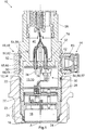
- an inventive pressure transmitter 10 is shown according to a preferred embodiment, which has a housing 12 with a wall 14 which encloses a cavity 15 with a longitudinal axis A.
- the wall 14 has a substantially hollow cylindrical shape with an opening 16, to which a pressure measuring cell 18 arranged in the cavity 15 adjoins.
- the pressure measuring cell 18 is mounted in a threaded sleeve 20, which serves as a process connection.
- the housing 12 is screwed to the rear side of the wall 14 and sealed with a first sealing element 22.
- the threaded sleeve 20 in turn has an external thread 23, with which the pressure transducer 10 can be screwed into a structural unit, not shown, for example, a container.
- the threaded sleeve 20 forms the process connection.
- the pressure measuring cell 18 is substantially aligned with an end face 24 of the process connection in order to minimize dead spaces in which dirt coming from the assembly could be kept as small as possible.
- the opening 16 is sealed by the pressure measuring cell 18, to which second sealing elements 26 are provided.
- a conversion unit 28 is arranged in the cavity 15, which cooperates with the pressure measuring cell 18. The conversion unit 28 receives the signals generated by the pressure measuring cell 18 as a function of the pressure prevailing in the structural unit and converts them into electrical signals.
- the conversion unit 28 is connected to a line device 30, which comprises a plurality of electrical lines and is connected to a pressure-tight passage device 32.
- the passage device 32 seals the cavity 15 to the other side from.
- the sealed part of the cavity 15 should be referred to as a pressure chamber 33.
- the bushing device 32 has a number of electrical feedthroughs in the form of conductive rods 34, to which the line device 30 can be connected and via which the electrical signals can be derived from the cavity 15.
- the guide rods 34 are attached to a glass bushing 36 in the bushing 32 pressure-tight and glued.
- a housing adapter 38 connects axially, which produces an electrical and mechanical connection to an electronics housing, not shown.
- the housing adapter 38 is formed in the illustrated example as a separate cavity 40 of the housing 12, but may also be welded to the wall 14 of the housing 12. In the example shown, the cavity 40 has a diameter which is smaller than the diameter of the pressure chamber 33.
- the wall 14 has a bore 42 which completely penetrates the wall 14 and is in communication with the pressure chamber 33.
- the bore 42 communicates outwardly with a pressure compensation device 44, which ensures the pressure equalization between the pressure chamber 33 and the environment and in particular causes a compensation for fluctuations in the ambient pressure.
- the pressure compensation device 44 is adjustable by means of an adjusting unit 46 in position.
- the adjusting unit 46 comprises a ring 48, which can be pushed onto a lateral surface 50 of the wall 14.
- the ring 48 has an inner surface 52, which comes into contact with the lateral surface 50 when it is pushed on.
- the position of use of the ring 48 on the housing 12 is determined by positioning means 54.
- the positioning means 54 comprise a stop 56, which is formed as a step 57 of the wall 14.
- the positioning means include 54 a locking ring 58 which defines the axial position of the ring 48 together with the stop 56.
- the ring 48 In its position of use, that is, when the ring 48 abuts against the stop 56, the ring 48 cooperates with a sealing device 60, which in the example shown has a first O-ring 62 and a second O-ring 64, which define a sealing space 65 which lies between the two O-rings 62, 64.
- a sealing device 60 which in the example shown has a first O-ring 62 and a second O-ring 64, which define a sealing space 65 which lies between the two O-rings 62, 64.
- the wall 14 of the housing 12 an annular recess 66 which is closed in itself and communicates with the bore 42.
- the annular recess 66 in turn communicates with the pressure compensation device 44, which is screwed into a connection section 68.
- the annular recess 66 is formed as a circumferential annular groove which is introduced into the surface 52 of the ring 48.
- the ring 48 To postpone the ring 48 on the lateral surface 50, it is pushed over the housing adapter 38.
- a shoulder 70 is provided on the housing 12 as a stop for the ring 48.
- the ring 48 has at both ends of its inner surface 52 each have a chamfer 74, on the one hand facilitate the sliding and also ensure that the two O-rings 62, 64 are not damaged.
- only one of the chamfers 74 (the front) is required in terms of assembly technology, it is achieved with the illustrated embodiment that the ring 48 does not have to be mounted in a specific orientation.
- the ring 48 can be pushed by means of the chamfer 74 on the locking ring 58 and further on the lateral surface 50 until it rests against the stop 56.
- the locking ring 58 is positioned so that the ring 48 then has no or only a negligible axial play, but can be rotated on the two O-rings 62, 64 about the longitudinal axis A, so that the pressure compensation device 44 can be positioned so that it is best protected against contamination.
- the ring 48 itself may be made of stainless steel, preferably stainless steel, machined. Alternatively, it can also be produced by die-casting, for which, however, suitable metal types must be used. Production by injection molding is also possible, whereby a plastic or powder injection molding process can be used. In the powder injection molding process, a stainless steel powder can be used.
Landscapes
- Physics & Mathematics (AREA)
- General Physics & Mathematics (AREA)
- Measuring Fluid Pressure (AREA)
Priority Applications (1)
| Application Number | Priority Date | Filing Date | Title |
|---|---|---|---|
| PL15156689T PL2913651T3 (pl) | 2014-02-26 | 2015-02-26 | Przetwornik ciśnienia z urządzeniem wyrównującym ciśnienie |
Applications Claiming Priority (1)
| Application Number | Priority Date | Filing Date | Title |
|---|---|---|---|
| DE102014102483.4A DE102014102483B4 (de) | 2014-02-26 | 2014-02-26 | Druckmessumformer mit Druckausgleichsvorrichtung |
Publications (2)
| Publication Number | Publication Date |
|---|---|
| EP2913651A1 EP2913651A1 (de) | 2015-09-02 |
| EP2913651B1 true EP2913651B1 (de) | 2018-05-16 |
Family
ID=52577749
Family Applications (1)
| Application Number | Title | Priority Date | Filing Date |
|---|---|---|---|
| EP15156689.0A Active EP2913651B1 (de) | 2014-02-26 | 2015-02-26 | Druckmessumformer mit Druckausgleichsvorrichtung |
Country Status (4)
| Country | Link |
|---|---|
| EP (1) | EP2913651B1 (pl) |
| DE (1) | DE102014102483B4 (pl) |
| HU (1) | HUE038674T2 (pl) |
| PL (1) | PL2913651T3 (pl) |
Cited By (3)
| Publication number | Priority date | Publication date | Assignee | Title |
|---|---|---|---|---|
| WO2024028236A1 (de) | 2022-08-03 | 2024-02-08 | Ifm Electronic Gmbh | Druckmessgerät zum einsatz in einer explosionsgefährdeten umgebung |
| DE102023120199A1 (de) | 2022-08-03 | 2024-02-08 | Ifm Electronic Gmbh | Druckmessgerät zum Einsatz in einer explosionsgefährdeten Umgebung |
| DE102023120514A1 (de) | 2022-08-03 | 2024-02-08 | Ifm Electronic Gmbh | Kapazitive Druckmesszelle und Druckmessgerät mit einer solchen Druckmesszelle, insbesondere zum Einsatz in einer explosionsgefährdeten Umgebung |
Families Citing this family (5)
| Publication number | Priority date | Publication date | Assignee | Title |
|---|---|---|---|---|
| DE102015215991B3 (de) * | 2015-08-21 | 2017-01-19 | Ifm Electronic Gmbh | Messgerät für die Prozessmesstechnik mit verdrehbarer Entlüftungshülse |
| DE102019209030B3 (de) * | 2019-06-21 | 2020-09-24 | Metallux Ag | Drucksensoreinrichtung |
| CN114267985B (zh) * | 2020-09-16 | 2025-04-11 | 中国船舶重工集团公司第七六0研究所 | 一种用于水下测压的密封连接装置 |
| CN113654713A (zh) * | 2021-07-15 | 2021-11-16 | 重庆市伟岸测器制造股份有限公司 | 一种压力平衡体系 |
| CN113670507A (zh) * | 2021-07-15 | 2021-11-19 | 重庆市伟岸测器制造股份有限公司 | 一种压差传感器压力平衡体系 |
Family Cites Families (5)
| Publication number | Priority date | Publication date | Assignee | Title |
|---|---|---|---|---|
| US4414851A (en) * | 1981-08-28 | 1983-11-15 | Motorola, Inc. | Gauge pressure sensor |
| DE10316033A1 (de) * | 2003-04-07 | 2004-10-21 | Endress + Hauser Gmbh + Co. Kg | Relativdruckmeßumformer |
| DE102006049942B4 (de) | 2006-10-19 | 2013-10-02 | Endress + Hauser Gmbh + Co. Kg | Druckmittler, Drucksensor mit Druckmittler und Verfahren zum Herstellen eines Druckmittlers |
| DE102007039297B3 (de) | 2007-08-20 | 2009-02-05 | Vega Grieshaber Kg | Druckmesseinrichtung |
| DE102012201018B4 (de) * | 2012-01-24 | 2016-03-31 | Ifm Electronic Gmbh | Messgerät mit am Gehäuse vorgesehenem Luftdurchgang |
-
2014
- 2014-02-26 DE DE102014102483.4A patent/DE102014102483B4/de active Active
-
2015
- 2015-02-26 EP EP15156689.0A patent/EP2913651B1/de active Active
- 2015-02-26 PL PL15156689T patent/PL2913651T3/pl unknown
- 2015-02-26 HU HUE15156689A patent/HUE038674T2/hu unknown
Non-Patent Citations (1)
| Title |
|---|
| None * |
Cited By (5)
| Publication number | Priority date | Publication date | Assignee | Title |
|---|---|---|---|---|
| WO2024028236A1 (de) | 2022-08-03 | 2024-02-08 | Ifm Electronic Gmbh | Druckmessgerät zum einsatz in einer explosionsgefährdeten umgebung |
| DE102023120198A1 (de) | 2022-08-03 | 2024-02-08 | Ifm Electronic Gmbh | Druckmessgerät zum Einsatz in einer explosionsgefährdeten Umgebung |
| DE102023120199A1 (de) | 2022-08-03 | 2024-02-08 | Ifm Electronic Gmbh | Druckmessgerät zum Einsatz in einer explosionsgefährdeten Umgebung |
| WO2024028237A1 (de) | 2022-08-03 | 2024-02-08 | Ifm Electronic Gmbh | Druckmessgerät zum einsatz in einer explosionsgefährdeten umgebung |
| DE102023120514A1 (de) | 2022-08-03 | 2024-02-08 | Ifm Electronic Gmbh | Kapazitive Druckmesszelle und Druckmessgerät mit einer solchen Druckmesszelle, insbesondere zum Einsatz in einer explosionsgefährdeten Umgebung |
Also Published As
| Publication number | Publication date |
|---|---|
| PL2913651T3 (pl) | 2018-12-31 |
| HUE038674T2 (hu) | 2018-11-28 |
| DE102014102483A1 (de) | 2015-08-27 |
| DE102014102483B4 (de) | 2021-05-27 |
| EP2913651A1 (de) | 2015-09-02 |
Similar Documents
| Publication | Publication Date | Title |
|---|---|---|
| DE102014102483B4 (de) | Druckmessumformer mit Druckausgleichsvorrichtung | |
| EP0594808B1 (de) | Vorrichtung zum messen von druck und differenzdruck mit dreiteiligem gewindegehäuse und einem winkelring | |
| EP3266084B1 (de) | Kabelabdichtung | |
| EP3380814B1 (de) | Explosionsgeschütztes gehäuse für mittel zum senden und empfangen elektromagnetischer strahlung | |
| DE102006043324A1 (de) | Steckfühler zur kombinierten Druck- und Temperaturmessung | |
| DE102014002660A1 (de) | Vorrichtung zur Aufnahme eines Temperatursensors | |
| EP2364790A1 (de) | Verfahren zum Verbinden eines Endabschnitts einer Leitung | |
| EP3175207B1 (de) | Druckmittler und drucksensor mit druckmittler | |
| EP2354770B1 (de) | Messsonde | |
| EP2569602B1 (de) | Anordnung zur verbindung eines messgeräts mit einem das zu messende medium enthaltenden behältnis | |
| EP1611422B1 (de) | Relativdruckmessumformer | |
| WO2008046768A1 (de) | Druckmittler, drucksensor mit druckmittler und verfahren zum herstellen eines druckmittlers | |
| DE102008054991A1 (de) | Differenzdruckmessumformer | |
| DE102010039866A1 (de) | Vorrichtung zur Bestimmung einer chemischen und/oder physikalischen Prozessgröße mit einem Kupplungssystem | |
| EP3458821B1 (de) | Verfahren zum herstellen eines druckmittlersystems | |
| EP2574895B1 (de) | Messanordnung für die Prozessmesstechnik mit einem Universal-Prozessanschluss | |
| DE102014112113A1 (de) | Druckschalter | |
| DE102011088736A1 (de) | Einbauarmatur mit einer Dichtungsvorrichtung | |
| EP4038352B1 (de) | Hygienegerechter adapter für feldgerät | |
| DE202015100786U1 (de) | Sensor mit einem Gehäuse und einem Montagestück | |
| EP2963323B1 (de) | Verwendung eines Rohrleitungsverbinders zum Führen von Wasserstoffgas sowie Rohrleitungsverbinder mit Wasserstoffgas | |
| EP1930710A2 (de) | Vorrichtung zum Ermitteln einer Zustandsgröse einer zu untersuchenden Einrichtung | |
| EP4370806B1 (de) | Feldgerät mit einem sensor zur erfassung einer physikalischen messgrösse | |
| WO2006030004A2 (de) | Gehäuse und gehäuseverbindung für sensoren | |
| DE102017121158B3 (de) | Druckmittler und Bauteilanordnung zum Schützen eines Druckmessumformers vor der Einwirkung eines unter einem zu messenden Druck stehenden Fluids sowie Verfahren zum Verschweißen eines Druckmessumformers mit einem Druckmittler |
Legal Events
| Date | Code | Title | Description |
|---|---|---|---|
| PUAI | Public reference made under article 153(3) epc to a published international application that has entered the european phase |
Free format text: ORIGINAL CODE: 0009012 |
|
| AK | Designated contracting states |
Kind code of ref document: A1 Designated state(s): AL AT BE BG CH CY CZ DE DK EE ES FI FR GB GR HR HU IE IS IT LI LT LU LV MC MK MT NL NO PL PT RO RS SE SI SK SM TR |
|
| AX | Request for extension of the european patent |
Extension state: BA ME |
|
| 17P | Request for examination filed |
Effective date: 20160212 |
|
| RBV | Designated contracting states (corrected) |
Designated state(s): AL AT BE BG CH CY CZ DE DK EE ES FI FR GB GR HR HU IE IS IT LI LT LU LV MC MK MT NL NO PL PT RO RS SE SI SK SM TR |
|
| GRAP | Despatch of communication of intention to grant a patent |
Free format text: ORIGINAL CODE: EPIDOSNIGR1 |
|
| STAA | Information on the status of an ep patent application or granted ep patent |
Free format text: STATUS: GRANT OF PATENT IS INTENDED |
|
| INTG | Intention to grant announced |
Effective date: 20180104 |
|
| GRAS | Grant fee paid |
Free format text: ORIGINAL CODE: EPIDOSNIGR3 |
|
| GRAA | (expected) grant |
Free format text: ORIGINAL CODE: 0009210 |
|
| STAA | Information on the status of an ep patent application or granted ep patent |
Free format text: STATUS: THE PATENT HAS BEEN GRANTED |
|
| AK | Designated contracting states |
Kind code of ref document: B1 Designated state(s): AL AT BE BG CH CY CZ DE DK EE ES FI FR GB GR HR HU IE IS IT LI LT LU LV MC MK MT NL NO PL PT RO RS SE SI SK SM TR |
|
| REG | Reference to a national code |
Ref country code: GB Ref legal event code: FG4D Free format text: NOT ENGLISH |
|
| REG | Reference to a national code |
Ref country code: CH Ref legal event code: EP |
|
| REG | Reference to a national code |
Ref country code: IE Ref legal event code: FG4D Free format text: LANGUAGE OF EP DOCUMENT: GERMAN |
|
| REG | Reference to a national code |
Ref country code: DE Ref legal event code: R096 Ref document number: 502015004253 Country of ref document: DE |
|
| REG | Reference to a national code |
Ref country code: AT Ref legal event code: REF Ref document number: 1000007 Country of ref document: AT Kind code of ref document: T Effective date: 20180615 |
|
| REG | Reference to a national code |
Ref country code: RO Ref legal event code: EPE |
|
| REG | Reference to a national code |
Ref country code: NL Ref legal event code: FP |
|
| REG | Reference to a national code |
Ref country code: LT Ref legal event code: MG4D |
|
| PG25 | Lapsed in a contracting state [announced via postgrant information from national office to epo] |
Ref country code: LT Free format text: LAPSE BECAUSE OF FAILURE TO SUBMIT A TRANSLATION OF THE DESCRIPTION OR TO PAY THE FEE WITHIN THE PRESCRIBED TIME-LIMIT Effective date: 20180516 Ref country code: FI Free format text: LAPSE BECAUSE OF FAILURE TO SUBMIT A TRANSLATION OF THE DESCRIPTION OR TO PAY THE FEE WITHIN THE PRESCRIBED TIME-LIMIT Effective date: 20180516 Ref country code: BG Free format text: LAPSE BECAUSE OF FAILURE TO SUBMIT A TRANSLATION OF THE DESCRIPTION OR TO PAY THE FEE WITHIN THE PRESCRIBED TIME-LIMIT Effective date: 20180816 Ref country code: NO Free format text: LAPSE BECAUSE OF FAILURE TO SUBMIT A TRANSLATION OF THE DESCRIPTION OR TO PAY THE FEE WITHIN THE PRESCRIBED TIME-LIMIT Effective date: 20180816 Ref country code: SE Free format text: LAPSE BECAUSE OF FAILURE TO SUBMIT A TRANSLATION OF THE DESCRIPTION OR TO PAY THE FEE WITHIN THE PRESCRIBED TIME-LIMIT Effective date: 20180516 Ref country code: ES Free format text: LAPSE BECAUSE OF FAILURE TO SUBMIT A TRANSLATION OF THE DESCRIPTION OR TO PAY THE FEE WITHIN THE PRESCRIBED TIME-LIMIT Effective date: 20180516 |
|
| REG | Reference to a national code |
Ref country code: HU Ref legal event code: AG4A Ref document number: E038674 Country of ref document: HU |
|
| PG25 | Lapsed in a contracting state [announced via postgrant information from national office to epo] |
Ref country code: RS Free format text: LAPSE BECAUSE OF FAILURE TO SUBMIT A TRANSLATION OF THE DESCRIPTION OR TO PAY THE FEE WITHIN THE PRESCRIBED TIME-LIMIT Effective date: 20180516 Ref country code: GR Free format text: LAPSE BECAUSE OF FAILURE TO SUBMIT A TRANSLATION OF THE DESCRIPTION OR TO PAY THE FEE WITHIN THE PRESCRIBED TIME-LIMIT Effective date: 20180817 Ref country code: HR Free format text: LAPSE BECAUSE OF FAILURE TO SUBMIT A TRANSLATION OF THE DESCRIPTION OR TO PAY THE FEE WITHIN THE PRESCRIBED TIME-LIMIT Effective date: 20180516 Ref country code: LV Free format text: LAPSE BECAUSE OF FAILURE TO SUBMIT A TRANSLATION OF THE DESCRIPTION OR TO PAY THE FEE WITHIN THE PRESCRIBED TIME-LIMIT Effective date: 20180516 |
|
| PG25 | Lapsed in a contracting state [announced via postgrant information from national office to epo] |
Ref country code: DK Free format text: LAPSE BECAUSE OF FAILURE TO SUBMIT A TRANSLATION OF THE DESCRIPTION OR TO PAY THE FEE WITHIN THE PRESCRIBED TIME-LIMIT Effective date: 20180516 Ref country code: EE Free format text: LAPSE BECAUSE OF FAILURE TO SUBMIT A TRANSLATION OF THE DESCRIPTION OR TO PAY THE FEE WITHIN THE PRESCRIBED TIME-LIMIT Effective date: 20180516 Ref country code: SK Free format text: LAPSE BECAUSE OF FAILURE TO SUBMIT A TRANSLATION OF THE DESCRIPTION OR TO PAY THE FEE WITHIN THE PRESCRIBED TIME-LIMIT Effective date: 20180516 Ref country code: CZ Free format text: LAPSE BECAUSE OF FAILURE TO SUBMIT A TRANSLATION OF THE DESCRIPTION OR TO PAY THE FEE WITHIN THE PRESCRIBED TIME-LIMIT Effective date: 20180516 |
|
| REG | Reference to a national code |
Ref country code: DE Ref legal event code: R097 Ref document number: 502015004253 Country of ref document: DE |
|
| PG25 | Lapsed in a contracting state [announced via postgrant information from national office to epo] |
Ref country code: IT Free format text: LAPSE BECAUSE OF FAILURE TO SUBMIT A TRANSLATION OF THE DESCRIPTION OR TO PAY THE FEE WITHIN THE PRESCRIBED TIME-LIMIT Effective date: 20180516 Ref country code: SM Free format text: LAPSE BECAUSE OF FAILURE TO SUBMIT A TRANSLATION OF THE DESCRIPTION OR TO PAY THE FEE WITHIN THE PRESCRIBED TIME-LIMIT Effective date: 20180516 |
|
| PLBE | No opposition filed within time limit |
Free format text: ORIGINAL CODE: 0009261 |
|
| STAA | Information on the status of an ep patent application or granted ep patent |
Free format text: STATUS: NO OPPOSITION FILED WITHIN TIME LIMIT |
|
| 26N | No opposition filed |
Effective date: 20190219 |
|
| PG25 | Lapsed in a contracting state [announced via postgrant information from national office to epo] |
Ref country code: SI Free format text: LAPSE BECAUSE OF FAILURE TO SUBMIT A TRANSLATION OF THE DESCRIPTION OR TO PAY THE FEE WITHIN THE PRESCRIBED TIME-LIMIT Effective date: 20180516 |
|
| PG25 | Lapsed in a contracting state [announced via postgrant information from national office to epo] |
Ref country code: LU Free format text: LAPSE BECAUSE OF NON-PAYMENT OF DUE FEES Effective date: 20190226 Ref country code: MC Free format text: LAPSE BECAUSE OF FAILURE TO SUBMIT A TRANSLATION OF THE DESCRIPTION OR TO PAY THE FEE WITHIN THE PRESCRIBED TIME-LIMIT Effective date: 20180516 |
|
| REG | Reference to a national code |
Ref country code: BE Ref legal event code: MM Effective date: 20190228 |
|
| REG | Reference to a national code |
Ref country code: IE Ref legal event code: MM4A |
|
| PG25 | Lapsed in a contracting state [announced via postgrant information from national office to epo] |
Ref country code: AL Free format text: LAPSE BECAUSE OF FAILURE TO SUBMIT A TRANSLATION OF THE DESCRIPTION OR TO PAY THE FEE WITHIN THE PRESCRIBED TIME-LIMIT Effective date: 20180516 |
|
| PG25 | Lapsed in a contracting state [announced via postgrant information from national office to epo] |
Ref country code: IE Free format text: LAPSE BECAUSE OF NON-PAYMENT OF DUE FEES Effective date: 20190226 |
|
| PG25 | Lapsed in a contracting state [announced via postgrant information from national office to epo] |
Ref country code: BE Free format text: LAPSE BECAUSE OF NON-PAYMENT OF DUE FEES Effective date: 20190228 |
|
| PG25 | Lapsed in a contracting state [announced via postgrant information from national office to epo] |
Ref country code: TR Free format text: LAPSE BECAUSE OF FAILURE TO SUBMIT A TRANSLATION OF THE DESCRIPTION OR TO PAY THE FEE WITHIN THE PRESCRIBED TIME-LIMIT Effective date: 20180516 |
|
| PG25 | Lapsed in a contracting state [announced via postgrant information from national office to epo] |
Ref country code: PT Free format text: LAPSE BECAUSE OF FAILURE TO SUBMIT A TRANSLATION OF THE DESCRIPTION OR TO PAY THE FEE WITHIN THE PRESCRIBED TIME-LIMIT Effective date: 20180917 Ref country code: MT Free format text: LAPSE BECAUSE OF FAILURE TO SUBMIT A TRANSLATION OF THE DESCRIPTION OR TO PAY THE FEE WITHIN THE PRESCRIBED TIME-LIMIT Effective date: 20180516 |
|
| REG | Reference to a national code |
Ref country code: AT Ref legal event code: MM01 Ref document number: 1000007 Country of ref document: AT Kind code of ref document: T Effective date: 20200226 |
|
| PG25 | Lapsed in a contracting state [announced via postgrant information from national office to epo] |
Ref country code: AT Free format text: LAPSE BECAUSE OF NON-PAYMENT OF DUE FEES Effective date: 20200226 Ref country code: CY Free format text: LAPSE BECAUSE OF FAILURE TO SUBMIT A TRANSLATION OF THE DESCRIPTION OR TO PAY THE FEE WITHIN THE PRESCRIBED TIME-LIMIT Effective date: 20180516 |
|
| PG25 | Lapsed in a contracting state [announced via postgrant information from national office to epo] |
Ref country code: IS Free format text: LAPSE BECAUSE OF FAILURE TO SUBMIT A TRANSLATION OF THE DESCRIPTION OR TO PAY THE FEE WITHIN THE PRESCRIBED TIME-LIMIT Effective date: 20180916 |
|
| PG25 | Lapsed in a contracting state [announced via postgrant information from national office to epo] |
Ref country code: MK Free format text: LAPSE BECAUSE OF FAILURE TO SUBMIT A TRANSLATION OF THE DESCRIPTION OR TO PAY THE FEE WITHIN THE PRESCRIBED TIME-LIMIT Effective date: 20180516 |
|
| P01 | Opt-out of the competence of the unified patent court (upc) registered |
Effective date: 20230626 |
|
| PGFP | Annual fee paid to national office [announced via postgrant information from national office to epo] |
Ref country code: PL Payment date: 20250218 Year of fee payment: 11 |
|
| REG | Reference to a national code |
Ref country code: CH Ref legal event code: U11 Free format text: ST27 STATUS EVENT CODE: U-0-0-U10-U11 (AS PROVIDED BY THE NATIONAL OFFICE) Effective date: 20260301 |
|
| PGFP | Annual fee paid to national office [announced via postgrant information from national office to epo] |
Ref country code: NL Payment date: 20260218 Year of fee payment: 12 |
|
| PGFP | Annual fee paid to national office [announced via postgrant information from national office to epo] |
Ref country code: HU Payment date: 20260225 Year of fee payment: 12 |
|
| PGFP | Annual fee paid to national office [announced via postgrant information from national office to epo] |
Ref country code: GB Payment date: 20260219 Year of fee payment: 12 |
|
| PGFP | Annual fee paid to national office [announced via postgrant information from national office to epo] |
Ref country code: DE Payment date: 20260217 Year of fee payment: 12 |
|
| PGFP | Annual fee paid to national office [announced via postgrant information from national office to epo] |
Ref country code: RO Payment date: 20260224 Year of fee payment: 12 |
|
| PGFP | Annual fee paid to national office [announced via postgrant information from national office to epo] |
Ref country code: FR Payment date: 20260219 Year of fee payment: 12 |
|
| PGFP | Annual fee paid to national office [announced via postgrant information from national office to epo] |
Ref country code: CH Payment date: 20260301 Year of fee payment: 12 |